WO2023182453A1 - Power transmission device - Google Patents
Power transmission device Download PDFInfo
- Publication number
- WO2023182453A1 WO2023182453A1 PCT/JP2023/011616 JP2023011616W WO2023182453A1 WO 2023182453 A1 WO2023182453 A1 WO 2023182453A1 JP 2023011616 W JP2023011616 W JP 2023011616W WO 2023182453 A1 WO2023182453 A1 WO 2023182453A1
- Authority
- WO
- WIPO (PCT)
- Prior art keywords
- power transmission
- chamber
- electric pump
- transmission device
- recess
- Prior art date
Links
- 230000005540 biological transmission Effects 0.000 title claims abstract description 107
- 230000007246 mechanism Effects 0.000 claims abstract description 48
- 230000002093 peripheral effect Effects 0.000 claims description 47
- 238000005192 partition Methods 0.000 claims description 15
- 230000013011 mating Effects 0.000 claims description 7
- 230000001105 regulatory effect Effects 0.000 description 15
- 238000010586 diagram Methods 0.000 description 10
- 238000009434 installation Methods 0.000 description 7
- 230000005484 gravity Effects 0.000 description 3
- 239000004575 stone Substances 0.000 description 3
- 230000012447 hatching Effects 0.000 description 2
- 230000004308 accommodation Effects 0.000 description 1
- 230000015572 biosynthetic process Effects 0.000 description 1
- 238000001816 cooling Methods 0.000 description 1
- 230000001050 lubricating effect Effects 0.000 description 1
- 230000008961 swelling Effects 0.000 description 1
- 238000004804 winding Methods 0.000 description 1
Images


Classifications
-
- F—MECHANICAL ENGINEERING; LIGHTING; HEATING; WEAPONS; BLASTING
- F04—POSITIVE - DISPLACEMENT MACHINES FOR LIQUIDS; PUMPS FOR LIQUIDS OR ELASTIC FLUIDS
- F04B—POSITIVE-DISPLACEMENT MACHINES FOR LIQUIDS; PUMPS
- F04B53/00—Component parts, details or accessories not provided for in, or of interest apart from, groups F04B1/00 - F04B23/00 or F04B39/00 - F04B47/00
-
- F—MECHANICAL ENGINEERING; LIGHTING; HEATING; WEAPONS; BLASTING
- F16—ENGINEERING ELEMENTS AND UNITS; GENERAL MEASURES FOR PRODUCING AND MAINTAINING EFFECTIVE FUNCTIONING OF MACHINES OR INSTALLATIONS; THERMAL INSULATION IN GENERAL
- F16H—GEARING
- F16H57/00—General details of gearing
- F16H57/02—Gearboxes; Mounting gearing therein
Definitions
- the present invention relates to a power transmission device.
- Patent Document 1 discloses a drive device for a vehicle.
- the electric oil pump is disposed at the bottom of the case with a portion exposed to the outside of the case.
- an external connector for power supply is provided at the top of the case.
- a power supply cable that connects the electric oil pump and the external connector is routed from the bottom to the top of the case.
- Components of the drive device such as a rotating body, are provided within the case.
- the power supply cable must be routed while avoiding interference with the components. Therefore, the routing of the power supply cable becomes complicated. Therefore, there is a need to make it easier to route the power supply cable within the case.
- An aspect of the present invention is a case that accommodates a power transmission mechanism; a control valve that controls hydraulic pressure supplied to the power transmission mechanism;
- a power transmission device comprising: an electric pump that supplies oil to the control valve;
- the said case is a first chamber that accommodates the power transmission mechanism; a second chamber disposed adjacent to the first chamber,
- the control valve and the electric pump are arranged vertically in the second chamber,
- a first recess that is recessed from above the electric pump toward the electric pump is provided in a region that overlaps the electric pump when viewed from above along the rotation axis of the electric pump
- the connector of the electric pump is a power transmission device in which a connecting portion with a mating connector is disposed within the first recess so as to face upward.
- the power supply cable can be more easily routed within the case.
- FIG. 1 is a schematic diagram showing a schematic configuration of a power transmission device.
- FIG. 2 is a schematic diagram of the case viewed from the first cover side.
- FIG. 3 is a schematic diagram of the housing section viewed from the front side of the vehicle.
- FIG. 4 is a sectional view of a main part of the housing.
- FIG. 5 is a sectional view of a main part of the housing.
- FIG. 6 is a sectional view of a main part of the housing.
- FIG. 7 is a sectional view of a main part of the housing.
- FIG. 8 is a sectional view of a main part of the housing.
- the power transmission device is a device having at least a power transmission mechanism, and the power transmission mechanism is, for example, at least one of a gear mechanism, a differential gear mechanism, and a speed reduction mechanism.
- the power transmission device 1 has a function of transmitting the output rotation of the engine, but the power transmission device 1 transmits the output rotation of at least one of the engine and the motor (rotating electric machine). It's fine as long as it's something you do.
- “Overlapping in a predetermined direction” means that a plurality of elements are lined up in a predetermined direction, and has the same meaning as "overlapping in a predetermined direction.”
- the "predetermined direction” is, for example, an axial direction, a radial direction, a gravity direction, a vehicle longitudinal direction, or the like. If a drawing shows multiple elements (parts, parts, etc.) lining up in a predetermined direction, there is a sentence in the description explaining that they overlap when viewed in the predetermined direction. It can be considered as.
- “Do not overlap when viewed in a predetermined direction” and “offset when viewed in a predetermined direction” mean that multiple elements are not lined up in a predetermined direction, and "do not overlap in a predetermined direction” , is synonymous with the expression “offset in a predetermined direction”.
- the "predetermined direction” is, for example, an axial direction, a radial direction, a gravity direction, a vehicle longitudinal direction (vehicle forward direction, vehicle backward direction), or the like. If a drawing shows that multiple elements (parts, parts, etc.) are not lined up in a predetermined direction, there is a sentence in the description explaining that they do not overlap when viewed in a predetermined direction. It can be considered as.
- the first element (component, section, etc.) is located between the second element (component, section, etc.) and the third element (component, section, etc.) when viewed from a predetermined direction" means In this case, the first element can be observed to be between the second and third elements.
- the "predetermined direction" includes an axial direction, a radial direction, a direction of gravity, a vehicle running direction (vehicle forward direction, vehicle backward direction), and the like.
- vehicle forward direction vehicle backward direction
- the first element is located between the second element and the third element when viewed in the radial direction. It can be said that it is located.
- Axial direction means the axial direction of the rotating shaft of the components that constitute the power transmission device.
- Ring direction means a direction perpendicular to the rotational axis of the components constituting the power transmission device.
- the parts are, for example, a motor, a gear mechanism, a differential gear mechanism, etc.
- “Vertical installation” of a control valve means that in the case of a control valve that has a basic configuration with a separate plate sandwiched between the valve bodies, the valve body of the control valve is placed horizontally with respect to the installation state of the power transmission device in the vehicle. This means that they are laminated in the same direction.
- the term "horizontal direction” as used herein does not mean the horizontal direction in a strict sense, but also includes cases where the stacking direction is tilted with respect to the horizontal line.
- vertical installation of a control valve means that the multiple pressure regulating valves (valve bodies) in the control valve are arranged in the vertical line VL direction based on the installation state of the power transmission device in the vehicle. This means that the valve is in place.
- a plurality of pressure regulating valves are arranged in the direction of the vertical line VL means that the pressure regulating valves in the control valve are arranged with their positions shifted in the direction of the vertical line VL.
- the plurality of pressure regulating valves do not need to be strictly lined up in a line in the vertical line VL direction.
- the plurality of pressure regulating valves are shifted in the direction of stacking of the valve bodies, and the vertical line VL They may be lined up in the same direction.
- the plurality of pressure regulating valves do not need to be lined up at intervals in the vertical line VL direction.
- the plurality of pressure regulating valves do not need to be adjacent to each other in the vertical line VL direction.
- pressure regulating valves lined up in the vertical line VL direction are arranged with their positions shifted in the stacking direction (horizontal line direction) of the valve body, the pressure regulating valves lined up in the vertical line VL direction are shifted when viewed from the stacking direction.
- This also includes cases where adjacent pressure regulating valves are provided in a positional relationship that partially overlaps.
- the multiple pressure regulating valves in the control valve are arranged in such a way that the moving direction of the valve body (spool valve) of the pressure regulating valve is along the horizontal direction.
- the moving direction of the valve body (spool valve) in this case is not limited to the horizontal direction in the strict sense.
- the moving direction of the valve body (spool valve) in this case is a direction along the rotation axis X of the power transmission device. In this case, the rotation axis X direction and the sliding direction of the valve body (spool valve) are the same.
- FIG. 1 is a schematic diagram illustrating a schematic configuration of a power transmission device 1.
- a power transmission device 1 mounted on a vehicle V has a housing HS that accommodates a power transmission mechanism.
- the housing HS includes a case 6, a first cover 7, a second cover 8, and a third cover 9.
- Power transmission mechanisms such as a torque converter T/C, a forward/reverse switching mechanism 2, a variator 3, a speed reduction mechanism 4, a differential device 5, and the like are housed inside the housing HS.
- an electric oil pump EOP, a mechanical oil pump MOP, a control valve CV, etc. are housed inside the housing HS.
- the output rotation of the engine ENG (drive source) is input to the forward/reverse switching mechanism 2 via the torque converter T/C.
- the rotation input to the forward/reverse switching mechanism 2 is input to the primary pulley 31 of the variator 3 in forward or reverse rotation.
- the rotation input to the primary pulley 31 is changed at a desired gear ratio, and the rotation is transferred to the output shaft 33 of the secondary pulley 32. is output from.
- the output rotation of the secondary pulley 32 is input to the differential device 5 (differential gear mechanism) via the reduction mechanism 4, and then transmitted to the drive wheels WH, WH via the left and right drive shafts 55A, 55B. .
- the forward/reverse switching mechanism 2 the torque converter T/C, and the output shaft of the engine ENG are arranged coaxially (concentrically) on the rotation axis X1 (first axis) of the primary pulley 31. Ru.
- the output shaft 33 of the secondary pulley 32 and the output gear 41 are coaxially arranged on the rotation axis X2 (second axis) of the secondary pulley 32.
- the idler gear 42 and the reduction gear 43 are coaxially arranged on a common rotation axis X3 (third axis).
- the final gear 45 and the drive shafts 55A and 55B are coaxially arranged on a common rotation axis X4 (fourth axis).
- these rotational axes X1 to X4 are set in a positional relationship in which they are parallel to each other.
- these rotational axes X1 to X4 will be collectively referred to as the rotational axis X of the power transmission device 1 (power transmission mechanism), if necessary.
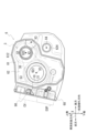
- FIG. 2 is a plan view of the case 6 viewed from the first cover 7 side.
- the power supply connector 90 is shown with cross hatching in order to make it easier to understand the arrangement of the power supply connector 90 located inside the first recess 10, which will be described later.
- the case 6 includes a cylindrical peripheral wall portion 61 and a partition wall portion 62.
- the peripheral wall portion 61 is provided along the rotation axis X of the power transmission device 1, and constitutes an outer wall portion of the power transmission device.
- the partition wall portion 62 is provided inside the peripheral wall portion 61 in a range that crosses the rotation axis (rotation axis X1 to rotation axis X4) of the power transmission device 1.
- the partition wall 62 divides the space inside the peripheral wall 61 into two in the direction of the rotation axis X1.
- One side of the partition wall portion 62 in the direction of the rotation axis X1 is the first chamber S1, and the other side is the third chamber S3.
- the case 6 and the second cover 8 are connected with bolts (not shown) with their joints 611 and 811 joined together. As a result, one opening of the case 6 is kept sealed by the second cover 8, forming a closed first chamber S1.
- the forward/reverse switching mechanism 2, the speed reduction mechanism 4, and the differential gear 5 are housed in the first chamber S1.
- the case 6 and the first cover 7 are connected with bolts (not shown) with their joints 612 and 711 joined together. As a result, the other opening of the case 6 is kept sealed by the first cover 7, forming a closed third chamber S3.
- the variator 3 is accommodated in the third chamber S3.
- through holes 621 and 622 are opened inside the peripheral wall portion 61.
- a through hole 624 is opened on the outside of the peripheral wall portion 61 .
- the through hole 621 is formed around the rotation axis X1.
- the input shaft 34 (see FIG. 1) of the primary pulley 31 passes through the through hole 621.
- the through hole 622 is formed around the rotation axis X2.
- the output shaft 33 (see FIG. 1) of the secondary pulley 32 passes through the through hole 622.
- the through hole 624 is formed around the rotation axis X4.
- the drive shaft 55A passes through the through hole 624.
- the primary pulley 31 is located lower than the secondary pulley 32 on the front side of the vehicle. Therefore, the portion of the peripheral wall portion 61 that surrounds the outer periphery of the primary pulley 31 is located furthest toward the front of the vehicle. A region of the peripheral wall portion 61 below the primary pulley 31 is recessed toward the rear of the vehicle so that it is located toward the rear of the vehicle as it goes downward.
- the first cover 7, which is assembled to the case 6 from the front side in the drawing also has a peripheral wall part 71 which is assembled to the peripheral wall part 61 from the direction of the rotation axis X (see FIG. 4).
- the peripheral wall portion 71 is formed in a shape that matches the peripheral wall portion 61 when viewed from the direction of the rotation axis X.
- a housing portion 68 is attached to the side surface on the front side of the vehicle.
- the housing portion 68 is provided with an opening facing toward the front side of the vehicle.
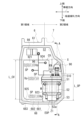
- FIG. 3 is a diagram of the housing portion 68 viewed from the front side of the vehicle.
- the second chamber S2 viewed from the front side of the vehicle is schematically shown together with other components (case 6 and first cover 7) of the housing HS.
- the region of the joint portion 683 located on the near side of the paper is shown with crossed hatching.
- the appearance of the control valve CV is schematically shown.
- a power supply line 97 connecting the electric oil pump EOP and the power supply connector 90 and a signal line 96 connecting the control connector 98 to the control valve CV and the electric oil pump EOP are schematically shown.
- the accommodating portion 68 includes a wall portion 682 and a peripheral wall portion 681 that surrounds the entire outer periphery of the wall portion 682 when viewed from the front side of the vehicle.
- the end surface of the peripheral wall portion 681 on the near side in the drawing forms a joint portion 683 with the third cover 9.
- a joint portion 911 on the third cover 9 side is joined to the joint portion 683 over the entire circumference.
- the accommodating portion 68 and the third cover 9 are connected with bolts (not shown) with their joint portions 683 and 911 joined together.
- a closed second chamber S2 is formed.
- the second chamber S2 accommodates a control valve CV and an electric oil pump EOP.
- the wall portion 682 of the housing portion 68 is oriented along the rotation axis X of the power transmission device 1.
- the accommodating portion 68 is formed to have a range in the rotation axis X direction (in the left-right direction in the figure) extending from a region adjacent to the peripheral wall portion 61 of the case 6 to the side of the first cover 7.
- approximately half the area (first area) on the second cover 8 side (right side in the figure) is integrated with the peripheral wall portion 61 on the case 6 side. ing.
- the approximately half area (second area) on the first cover 7 side is provided on the vehicle front side of the first cover 7 with a gap between it and the outer periphery of the first cover 7 .
- control valve CV has a basic configuration in which a separate plate 920 is sandwiched between valve bodies 921, 921.
- a hydraulic control circuit (not shown) is formed inside the control valve CV.
- the hydraulic control circuit is provided with a solenoid that is driven based on a command from a control device (not shown) and a pressure regulating valve (spool valve SP) that is operated by signal pressure generated by the solenoid.
- the control valve CV is placed vertically with the stacking direction of the valve bodies 921, 921 aligned with the longitudinal direction of the vehicle (in the paper, front to back direction). .
- the control valve CV is vertically placed so as to satisfy the following conditions.
- (a) A plurality of spool valves SP in the control valve CV are lined up in the vertical line VL direction (vertical direction) based on the installation state of the power transmission device 1 in the vehicle V,
- the direction Xp is along the horizontal direction.
- the forward and backward movement direction of the spool valve within the control valve is arranged along the horizontal direction. Furthermore, the spool valve within the control valve is arranged with its position shifted in the vertical line VL direction. Therefore, the forward and backward movement of the spool valve is not obstructed, and the second chamber S2 is prevented from increasing in size in the longitudinal direction of the vehicle.
- the control valve CV When viewed from the front side of the vehicle, the control valve CV has a substantially L-shape in which a notch 923 is provided in a substantially rectangular valve body 921.
- the notch 923 is provided to avoid interference with the electric oil pump EOP.
- a portion of the second cover 8 side (left side in the figure) of the electric oil pump EOP is accommodated in the notch 923.
- the length L_CV of the control valve CV in the direction of the vertical line VL is longer than the length L_OP of the electric oil pump EOP in the direction of the vertical line VL (L_CV>L_OP). Therefore, when viewed from the direction of the vertical line VL, a part of the electric oil pump EOP is provided in a positional relationship overlapping with the control valve CV.
- control valve CV and the electric oil pump EOP are lined up in the direction of the rotation axis X of the power transmission device 1 (in the left-right direction in the figure).
- the control valve CV is provided so as to overlap the case 6 when viewed from the front side of the vehicle.
- the electric oil pump EOP is provided so as to overlap the first cover 7 when viewed from the front side of the vehicle.
- the electric oil pump EOP has a basic configuration in which a control section 51, a motor section 52, and a pump section 53 are arranged in series in the direction of the rotation axis Z1 of the motor M.
- the electric oil pump EOP is provided with a rotation axis Z1 perpendicular to a rotation axis X of the power transmission device 1. In this state, the electric oil pump EOP is placed vertically in such a direction that the pump section 53 is located at the lower side of the second chamber S2, and the control section 51 is located at the upper side of the second chamber S2.
- FIG. 4 is a diagram schematically showing a cross section of the housing HS taken along line AA in FIG.
- a cross section of the bulging portion 69 in the second chamber S2 is schematically shown together with a cross section of the peripheral wall portion 71 of the first cover 7 located on the rear side of the vehicle.
- FIG. 5 is a diagram schematically showing a cross section of the housing HS taken along the line AA in FIG.
- a cross section around the motor portion 52 of the electric oil pump EOP is schematically shown.
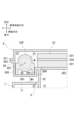
- FIG. 6 is a diagram schematically showing a cross section of the housing HS taken along line BB in FIG. FIG.
- FIG. 6 schematically shows the first recess 10 provided in the accommodating portion 68 and the arrangement of the power supply connector 90 in the first recess 10.
- FIG. 7 is a diagram schematically showing a cross section of the housing HS taken along line CC in FIG.
- FIG. 7 schematically shows the positional relationship between the first recess 10 provided in the accommodating portion 68 and the second recess 20 provided in the third cover 9.
- components bottom wall part 691, side wall part 694, side wall part 695, motor part 52
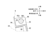
- FIG. 8 is a diagram schematically showing a cross section of the housing HS taken along line AA in FIG.
- FIG. 8 shows the area around the second recess 20 as seen from the engine ENG side.
- FIG. 4, FIG. 6, and FIG. 7 show how the power supply connector 90 and the electric oil pump EOP are connected via the power supply line 97, and how the control connector 98 and the electric oil pump EOP are connected via the signal line 96.
- the manner of connection with the control valve CV is simply described.
- a bulging portion 69 that functions as a housing portion for the electric oil pump EOP is provided in an area overlapping with the first cover 7 when viewed from the front side of the vehicle.
- the bulging portion 69 is formed by bulging the wall portion 682 toward the first cover 7 (the right side in FIG. 4).
- the bottom wall portion 691 of the bulging portion 69 is located at a distance of a depth D69 toward the first cover 7 when viewed from the wall portion 682.
- a portion of the electric oil pump EOP on the first cover 7 side is accommodated within the bulge 69.
- a portion of the electric oil pump EOP is accommodated in the bulging portion 69, so that the side edge 51a of the electric oil pump EOP on the vehicle front side and the side surface 921a of the control valve CV on the vehicle front side are substantially flush with each other.
- the electric oil pump EOP is arranged in the second chamber S2.
- the bulging portion 69 is formed with a length L69 in the rotation axis Z1 direction that can accommodate the electric oil pump EOP.
- the lower wall portion 692 of the bulging portion 69 is located on an extension of the peripheral wall portion 681 of the housing portion 68 .
- the upper wall portion 693 of the bulging portion 69 extends above the electric oil pump EOP toward the front side of the vehicle.
- the upper wall portion 693 is connected to the first wall portion 684 on the accommodating portion 68 side on the vehicle front side with respect to the rotation axis Z1.
- a first recess 10 is formed above the bulge 69 in the direction of the rotation axis Z1.
- the first recess 10 has a part of the area that overlaps with the electric oil pump EOP when viewed from the rotation axis Z1 direction, a lower side in the rotation axis Z1 direction, and a vehicle front side (upper side in the figure). It is a space created by recessing the area. That is, in the vertical line VL direction (vertical direction) along the rotation axis Z1 of the electric oil pump EOP in the housing part 68, the area located above the electric oil pump EOP in the housing part 68 is moved downward on the electric oil pump EOP side. It is formed by making a depression.
- the first recess 10 When viewed from the direction of the rotation axis Z1, the first recess 10 includes a first wall 684 and a second wall 685 on the accommodating part 68 side, a partition wall 62 on the case 6 side, and a peripheral wall 71 on the first cover 7 side. It is an enclosed space. Therefore, the first recess 10 is also surrounded by the first chamber S1, the second chamber S2, and the third chamber S3 in the housing HS.
- An upper wall portion 693 (see FIG. 4) of the bulging portion 69 for accommodating the electric oil pump EOP described above is located on the back side of the first recess 10 in the drawing.
- the first recess 10 is formed with its opening facing upward of the power transmission device 1. Furthermore, the first recess 10 is also open to one side in the vehicle width direction (to the left in FIG. 7).
- a power supply connector (power supply connector 90) is located within the first recess 10. As shown in FIG. 6, the power supply connector 90 has a connection portion 901 with a mating connector. The connection portion 901 is provided within the first recess 10 with the connection port for connecting to the mating connector facing upward.
- connection portion 901 of the power supply connector 90 When viewed from above in the direction of the vertical line VL, the connection portion 901 of the power supply connector 90 is provided in a positional relationship that completely overlaps the first recess 10. Further, the connecting portion 901 is provided at a position completely overlapping the first recess 10 when viewed from the direction of the rotation axis X of the power transmission device 1 (see FIG. 4). Therefore, the connecting portion 901 of the power feeding connector 90 is provided without protruding outward from the outer periphery of the housing HS (third cover 9, first cover 7, accommodating portion 68). That is, the connecting portion 901 is housed in the first recess 10 located inside the outer frame of the housing HS without protruding outward from the outer frame of the housing HS.
- the lower part of the connecting part 901 on the back side of the paper is connected to the base part 902 (see FIG. 6).
- the base 902 passes through a mounting hole 684a provided in the first wall 684.
- a region of the base portion 902 located within the second chamber S2 is connected to a connection portion 903 with the power supply line 97.
- the power supply connector 90 is electrically connected to the control section 51 (connection section 510) of the electric oil pump EOP via a power supply line 97.
- the attachment hole 684a in the first wall portion 684 is provided at a position upwardly away from the upper wall portion 693 of the bulging portion 69. As shown in FIG. Therefore, as shown in FIG. 3, the power supply connector 90 is located above the electric oil pump EOP.
- the length L_OP of the electric oil pump EOP in the direction of the vertical line VL is shorter than the length L_CV of the control valve CV in the direction of the vertical line VL (L_OP ⁇ L_CV). Therefore, if the lower end 925 of the control valve CV and the lower end 53a of the electric oil pump EOP are aligned in the second chamber S2, the available Space is secured.
- the power supply connector 90 is arranged in this available space.
- the electric oil pump EOP is arranged with the connecting portion 510 to the power supply line 97 facing upward in the vertical line VL direction. Therefore, the connection portion 510 is located directly below the power supply connector 90. Therefore, the connecting portion 510 of the electric oil pump EOP and the power supply connector 90 can be electrically connected over the shortest distance. This allows the power supply line 97 to be shortened. Furthermore, after the electric oil pump EOP is installed in the second chamber S2, the electric oil pump EOP and the power supply connector 90 can be easily connected.
- the first wall portion 684 to which the power supply connector 90 is attached extends upward along the rotation axis Z1 at a position overlapping the control valve CV when viewed from the vehicle width direction.
- the peripheral wall portion 91 of the third cover 9 is in contact with an area above the mounting hole 684a from the front side of the vehicle.
- the first wall portion 684 and the peripheral wall portion 91 are in contact with each other at a height exceeding the upper side 924 of the control valve CV.
- the first wall portion 684 extends on the extension of the joint portion 683 of the housing portion 68 in a direction approaching the control valve CV (to the right in the figure).
- the first wall portion 684 is connected to the second wall portion 685 on one side of the control valve CV in the vehicle width direction.
- the second wall portion 685 extends toward the first cover 7 (lower side in the figure) along the side edge of the control valve CV.
- the second wall portion 685 is connected to the wall portion 682 from the front side of the vehicle.
- the second wall portion 685 is provided in a positional relationship overlapping with the side wall portion 694 of the bulge portion 69 described above when viewed from the direction of the rotation axis Z1.
- the side wall portion 695 on the opposite side of the bulging portion 69 extends on the extension of the peripheral wall portion 681 of the housing portion 68 toward the first cover 7 side (lower side in the figure).
- the first wall portion 684 and the second wall portion 685 are recessed toward the vehicle front side than the wall portion 682, with the wall portion 682 supporting the control valve CV as a reference. It is located in such a way that By providing the first wall portion 684 and the second wall portion 685 in this manner, they participate in the formation of the first recess 10.
- the peripheral wall portion 71 of the first cover 7 is located on the rear side of the vehicle when viewed from the first wall portion 684.
- the first recess 10 is formed between the first wall 684 and the peripheral wall 71 in the vehicle longitudinal direction.
- the upper wall 693 of the bulge 69 described above is located on the back side of the first recess 10 in the drawing.
- the connecting portion 691a between the top wall portion 693 and the bottom wall portion 691 forms an arcuate outer periphery in a cross-sectional view along the rotation axis Z1.
- the connecting portion 691a has reached a position where it overlaps the peripheral wall portion 71 of the first cover 7 in the vertical line VL direction.
- the gap between the accommodating portion 68 and the peripheral wall portion 71 has a minimum width Wmin at the connecting portion 691a.
- the distance Wh between the bottom wall portion 691 and the peripheral wall portion 71 in the vehicle longitudinal direction becomes narrower as it goes upward in the vertical line VL direction.
- the region of the bottom wall portion 691 on the connection portion 691a side and the peripheral wall portion 71 are provided in an overlapping positional relationship. Therefore, even if a foreign object such as a stone is thrown up and enters between the bottom wall part 691 and the peripheral wall part 71 when the vehicle V equipped with the power transmission device 1 is running, it will not be located above the bulge part 69. It becomes difficult to reach the first recessed portion 10.
- the third cover 9 that covers the opening of the housing portion 68 on the vehicle front side includes a cover portion 92 having a size that covers the opening of the second chamber S2, a peripheral wall portion 91 that surrounds the entire outer periphery of the cover portion 92, has.
- a second recess 20 is formed in an area above the control valve CV in the direction of the rotation axis Z1.
- the second recess 20 is a space formed by recessing a part of the region of the third cover 9 that overlaps with the control valve CV toward the lower side and the rear side of the vehicle in the rotation axis Z1 direction. .
- the second recess 20 is located on the front side of the vehicle on the engine ENG (see FIG. 1) side when viewed from the first recess 10 described above. As shown in FIG. 7, the second recess 20 and the first recess 10 are shifted in position in the rotation axis X direction of the power transmission device 1 (horizontal direction in the figure) and in the longitudinal direction of the vehicle (vertical direction in the figure). It is provided.
- the second recess 20 includes a first wall 93 extending in the vehicle longitudinal direction, a second wall 94 extending in the vehicle width direction, and a first wall 94 extending in the vehicle width direction.
- the bottom wall portion 95 is formed between the portion 93 and the second wall portion 94 . Therefore, the second recess 20 opens to the front side of the vehicle and to the engine ENG side in the vehicle width direction (right side in FIG. 7).
- the first wall portion 93 is provided with a through hole 93a.
- the through hole 93a is provided with its opening facing the engine ENG side.
- a connector for control signals (control connector 98) is inserted into the through hole 93a from the engine ENG side (right side in FIG. 7).
- the control connector 98 has a connecting portion 981 with wiring for control signals located inside the second recess 20 on the outside of the third cover 9 .
- the control connector 98 is provided with the connecting portion 981 facing the engine ENG side, which is the opposite side from the electric oil pump EOP.
- the connecting portion 981 of the control connector 98 is provided in a positional relationship that completely overlaps the second recess 20 when viewed from above in the direction of the vertical line VL. Furthermore, the connecting portion 981 is provided at a position that completely overlaps the second recess 20 when viewed from the engine ENG side (see FIG. 8). Therefore, the connecting portion 981 of the control connector 98 is provided without protruding outward from the outer periphery of the housing HS (third cover 9).
- a signal line 96 is connected to a region of the control connector 98 located within the second chamber S2.
- the signal line 96 is connected to the control valve CV and the electric oil pump EOP (see FIG. 3). Therefore, the control valve CV and the electric oil pump EOP operate based on the control signal input via the signal line 96.
- connection portion 901 of the power supply connector 90 is provided at a position that completely overlaps the first recess 10 when viewed from the vertical line VL direction (see FIG. 7). . Further, the connecting portion 901 is provided at a position completely overlapping the first recess 10 when viewed from the direction of the rotation axis X of the power transmission device 1 (see FIG. 4). Therefore, the connection portion 901 of the power supply connector 90 is arranged within the first recess 10 with the connection port facing upward, without protruding outward from the outer periphery of the housing HS. Thereby, the power supply line can be connected to the connection part 901 from above the power transmission device 1.
- the connecting portion 981 of the control connector 98 is provided at a position completely overlapping the second recess 20 when viewed from the vertical line VL direction (see FIG. 7).
- the connecting portion 981 is provided at a position completely overlapping the second recess 20 when viewed from the engine ENG side (see FIG. 8). Therefore, the connection portion 981 of the control connector 98 is arranged within the second recess 20 with the connection port facing the engine ENG side without protruding outward from the outer periphery of the housing HS. Thereby, the control signal wiring can be connected to the connection portion 981 of the control connector 98 from the engine ENG side adjacent to the power transmission device 1 .
- the power transmission device 1 has the following configuration.
- the power transmission device 1 is A power transmission mechanism (torque converter T/C, forward/reverse switching mechanism 2, variator 3, deceleration mechanism 4, differential gear 5) that transmits the driving force from the engine ENG (drive source) to the drive wheels WH, WH; a housing HS (case) that houses the power transmission mechanism; a control valve CV that controls hydraulic pressure supplied to the power transmission mechanism; It has an electric oil pump EOP (electric pump) that supplies oil to the control valve CV.
- Housing HS is a first chamber S1 that accommodates a power transmission mechanism;
- the second chamber S2 is arranged adjacent to the first chamber S1.
- the control valve CV and the electric oil pump EOP are arranged vertically within the second chamber S2.
- a first recess 10 is recessed from above the electric oil pump EOP toward the electric oil pump EOP in a region overlapping the electric oil pump EOP when viewed from above along the rotation axis Z1 of the electric oil pump EOP. is provided.
- a power supply connector 90 (connector) of the electric oil pump EOP has a connecting portion 901 with a mating connector facing upward within the first recess 10 .
- a power supply line extending from a power supply source is connected to the connection portion 901 of the power supply connector 90, and driving power is supplied to the motor M of the electric oil pump EOP.
- This space is separate from the space for installing the housing HS of the power transmission device 1, and it is not preferable to use the limited space in the vehicle V for the connection portion 901 of the power supply connector 90. .
- the area of the housing portion 68 that overlaps with the electric oil pump EOP when viewed from the rotation axis Z1 direction and is located above the electric oil pump EOP is recessed downward on the electric oil pump EOP side. , forming the first recess 10.
- the connecting portion 901 of the power feeding connector 90 is placed within the first recess 10 with the connecting portion 901 facing upward.
- the connecting part 901 can be provided without significantly protruding outside the housing HS.
- power can be supplied to the electric oil pump EOP without further requiring a limited space on the vehicle V side, and the arrangement of the power supply connector 90 can be further optimized.
- the thickness of the second chamber S2 in the radial direction of the rotation axis X of the power transmission device 1 can be suppressed, thereby preventing the power transmission device 1 from increasing in size in the vehicle longitudinal direction. can.
- the power transmission device 1 is mounted on the vehicle V and is arranged with the second chamber S2 facing the horizontal direction, it is possible to suitably prevent the power transmission device 1 from increasing in size in the horizontal direction.
- the power supply connector 90 can be placed above the electric oil pump EOP and on the side of the control valve CV. You can secure a comfortable space.
- the connection part 901 of the power supply connector 90 is placed facing upward in the vertical line VL direction (vertical direction) based on the installed state of the power transmission device 1 in the vehicle V, access to the connection part 901 becomes difficult. It becomes easier. Therefore, after the power transmission device 1 is mounted on the vehicle V, the power supply line extending from the vehicle V side can be easily connected to the connection portion 901.
- the second recess 20 is provided in a region overlapping with the control valve CV when viewed from the direction of the rotation axis Z1 of the electric oil pump EOP.
- the control connector 98 of the electric oil pump EOP has a connecting portion 981 with a mating connector facing toward the side opposite to the electric oil pump EOP.
- the power supply connector 90 disposed within the first recess 10 is a connector for power supply to the electric oil pump EOP.
- control connector 98 can be provided without the connection portion 981 protruding from the outer periphery of the housing HS. Thereby, the control signal wiring can be connected without further requiring the limited space on the vehicle V side, and the arrangement of the control connector 98 can be further optimized.
- the first recess 10 and the second recess 20 are provided with positions shifted in the direction of the rotation axis X of the power transmission device 1.
- connection portion 981 of the control connector 98 is arranged in a positional relationship that overlaps with the second chamber S2 in both directions of the rotation axis X of the power transmission device 1 and the rotation axis Z1 of the electric oil pump EOP. Ru.
- the arrangement of the power supply connector 90 and the control connector 98 is further optimized.
- a control signal wiring is connected to the connection portion 981 of the control connector 98 from the direction of the rotation axis X of the power transmission device 1.
- the drive source and the power transmission device 1 are arranged adjacent to each other in the direction of the rotation axis X of the power transmission device 1.
- connection part 981 of the control connector 98 By arranging the connection part 981 of the control connector 98 toward the drive source side, the control signal wiring for the drive source and the control signal wiring connected to the connection part 981 of the control connector 98 can be combined. Therefore, wiring for control signals in the vehicle can be easily routed.
- the housing portion 68 of the housing HS includes a peripheral wall portion 681 surrounding the outer periphery of the second chamber S2; It has a third cover 9 (cover part) that closes the opening of the peripheral wall part 681.
- the first recess 10 is provided in the peripheral wall portion 681, and the second recess 20 is provided in the third cover 9.
- a signal line 96 extending from the control connector 98 is connected to the control valve CV and the electric oil pump EOP after the control valve CV and the electric oil pump EOP are installed in the housing part 68. If the control connector 98 is provided on the peripheral wall portion 681 side, the work of connecting the signal line 96 to the control valve CV and the electric oil pump EOP may become complicated.
- the control valve CV and the electric oil pump EOP to which the signal line 96 is connected are connected to the rotating shaft of the power transmission device 1 inside the peripheral wall portion 681. They are arranged side by side in the X direction.
- the control connector 98 When the control connector 98 is provided on the third cover 9, when closing the opening of the peripheral wall portion 681 with the third cover 9, the signal line of the control connector 98 supported by the third cover 9 is connected to the control valve CV. Can be easily connected to electric oil pump EOP. This facilitates the work of connecting the signal line 96 to the control valve CV and electric oil pump EOP.
- the third cover 9 to which the control connector 98 is assembled is prepared, and the prepared third cover 9 is assembled to the peripheral wall portion 681, thereby completing the installation of the control connector 98. This facilitates installation of the control connector 98.
- Housing HS is a partition wall 62 (support wall) that supports the rotation axes X1 to X4 of the power transmission mechanism; It has a wall portion 682 (dividing wall) that partitions the first chamber S1 and the second chamber S2 on one side of the partition wall portion 62.
- the wall portion 682 extends to the side of the third chamber S3 on the other side of the partition wall portion 62.
- the wall portion 682 (division wall) has a region overlapping with the first chamber S1 as the first region where the control valve CV is attached, and a region overlapping with the third chamber S3 as the electrically operated This is the second area where the oil pump EOP is attached (see Figure 3).
- a mounting hole 684a for the power supply connector 90 disposed in the first recess 10 is opened in the upper part of the second region.
- the first recess 10 is arranged in the upper part of the housing HS so as to be surrounded by the first chamber S1, the second chamber S2, and the third chamber S3.
- the second chamber S2 communicates with the first recess 10 via the attachment hole 684a.
- the second region which overlaps with the electric oil pump EOP, is a bulged portion 69 that bulges toward the third chamber S3.
- the upper side of the bulge 69 is the first recess 10 .
- a bottom wall portion 691 of the bulging portion 69 and a peripheral wall portion 71 surrounding the third chamber S3 are provided with an interval WH in the vehicle longitudinal direction.
- a gap exists between the bulge portion 69 and the peripheral wall portion 71. This gap continues from the lower end of the power transmission device 1 to the first recess 10. If the gap is formed in a straight line, there is a possibility that foreign objects thrown up, such as stones, may pass through this gap and reach the first recess 10 when the vehicle V equipped with the power transmission device 1 is running. There is. As shown in FIG.
- the bottom wall portion 691 of the bulging portion 69 and the peripheral wall portion 71 surrounding the third chamber S3 are provided in an overlapping positional relationship when viewed from the rotation axis Z1 direction (arrow D direction in the figure).
- the area between the bulge 69 and the peripheral wall 71 functions as a labyrinth seal. Therefore, when the vehicle V equipped with the power transmission device 1 is running, thrown up foreign objects such as stones are difficult to reach the first recess 10. Thereby, the connection portion 901 of the power supply connector 90 can be protected from any collisions such as foreign objects.
- the power transmission device 1 transmits the rotation of the engine ENG to the drive wheels WH, WH is illustrated, but the power transmission device 1 transmits the rotation of the engine ENG and the motor (rotating electric machine).
- the rotation may be transmitted to the drive wheels WH, WH.
- a one-motor, two-clutch type (the motor is arranged between the engine ENG and the power transmission device, the first clutch is arranged between the engine ENG and the motor, and the second clutch is arranged inside the power transmission device 1)
- It may also be a power transmission device of the following type.
- the power transmission device 1 has a speed change function, but the power transmission mechanism does not have a speed change function and simply decelerates (or may speed up). It's okay. If the power transmission device does not have a speed change function and is configured to decelerate the rotation of the motor and transmit it to the drive wheels WH, the oil OL for cooling the motor and the deceleration A hydraulic control circuit for supplying oil OL for lubricating the mechanism is arranged in the second chamber S2 together with the electric oil pump EOP. Further, in the above embodiment, the control unit of the power transmission device 1 is provided with the control valve CV, but the power transmission device 1 does not have a speed change mechanism, and the drive source is not the engine ENG. In the case of a motor (rotating electric machine), it may be a control unit including an inverter or the like that drives and controls the motor.
- Power transmission device Forward/reverse switching mechanism (power transmission mechanism) 3 Variator (power transmission mechanism) 4 Reduction mechanism (power transmission mechanism) 5 Differential device (power transmission mechanism) 6 Case 7 First cover (cover part) 71 Peripheral wall portion 9 Third cover (cover portion) 10 First recess 20 Second recess 62 Partition wall (support wall) 68 Storage part 681 Peripheral wall part 682 Wall part (partition wall) 684a Mounting hole 69 Swelling part 691 Bottom wall part 90 Power supply connector (connector) 901 Connection part 94 Signal line 98 Control connector 981 Connection part HS Housing (case) CV control valve EOP electric oil pump (electric pump) S1 1st chamber S1 2nd chamber S3 3rd chamber X, X1 to X4, Z1 Rotating shaft
Abstract
[Problem] To enable more simple routing of a power supply cable in a case. [Solution] A power transmission device includes: a case that houses a power transmission mechanism; a control valve that controls hydraulic pressure supplied to the power transmission mechanism; and an electric pump that supplies oil to the control valve. The case includes a first chamber that houses the power transmission mechanism, and a second chamber disposed adjacent to the first chamber. The control valve and the electric pump are disposed vertically in the second chamber. In the case, a first recess, which is recessed toward the electric pump from above the electric pump, is provided in a region that overlaps the electric pump when viewed from above along a rotational axis of the electric pump. A connector of the electric pump causes a connection portion of a mating-side connector to be disposed facing upward in the first recess.
Description
本発明は、動力伝達装置に関する。
The present invention relates to a power transmission device.
特許文献1には、車両用の駆動装置が開示されている。
Patent Document 1 discloses a drive device for a vehicle.
特許文献1の駆動装置では、電動オイルポンプが、ケースの外側に一部を露出させた状態でケースの下部に配置されている。駆動装置では、給電用の外部コネクタが、ケースの上部に設けられている。電動オイルポンプと外部コネクタとを接続する給電ケーブルは、ケース内の下部から上部まで配索されている。
In the drive device of Patent Document 1, the electric oil pump is disposed at the bottom of the case with a portion exposed to the outside of the case. In the drive device, an external connector for power supply is provided at the top of the case. A power supply cable that connects the electric oil pump and the external connector is routed from the bottom to the top of the case.
ケース内には、回転体などの駆動装置の構成要素が設けられている。給電ケーブルは、構成要素との干渉を避けつつ配索する必要がある。そのため、給電ケーブルの取り回しが複雑になる。
そこで、ケース内での給電ケーブルの配索をより簡便に行えるようにすることが求められている。 Components of the drive device, such as a rotating body, are provided within the case. The power supply cable must be routed while avoiding interference with the components. Therefore, the routing of the power supply cable becomes complicated.
Therefore, there is a need to make it easier to route the power supply cable within the case.
本発明のある態様は、
動力伝達機構を収容するケースと、
前記動力伝達機構に供給する油圧を制御するコントロールバルブと、
前記コントロールバルブにオイルを供給する電動ポンプと、を有する動力伝達装置であって、
前記ケースは、
前記動力伝達機構を収容する第1室と、
前記第1室に隣接配置された第2室と、を有し、
前記コントロールバルブと前記電動ポンプは、前記第2室内で縦置き配置されており、
前記ケースでは、前記電動ポンプの回転軸に沿う上方から見て前記電動ポンプと重なる領域に、前記電動ポンプの上方から前記電動ポンプ側に窪んだ第1凹部が設けられており、
前記電動ポンプのコネクタが、相手側コネクタとの接続部を、前記第1凹部内で上方を向けて配置させている、動力伝達装置である。 An aspect of the present invention is
a case that accommodates a power transmission mechanism;
a control valve that controls hydraulic pressure supplied to the power transmission mechanism;
A power transmission device comprising: an electric pump that supplies oil to the control valve;
The said case is
a first chamber that accommodates the power transmission mechanism;
a second chamber disposed adjacent to the first chamber,
The control valve and the electric pump are arranged vertically in the second chamber,
In the case, a first recess that is recessed from above the electric pump toward the electric pump is provided in a region that overlaps the electric pump when viewed from above along the rotation axis of the electric pump,
The connector of the electric pump is a power transmission device in which a connecting portion with a mating connector is disposed within the first recess so as to face upward.
本発明のある態様によれば、ケース内での給電ケーブルの配索をより簡便に行える。
According to an aspect of the present invention, the power supply cable can be more easily routed within the case.
始めに、本明細書における用語の定義を説明する。
動力伝達装置は、少なくとも動力伝達機構を有する装置であり、動力伝達機構は、例えば、歯車機構と差動歯車機構と減速機構の少なくともひとつである。
以下の実施形態では、動力伝達装置1がエンジンの出力回転を伝達する機能を有する場合を例示するが、動力伝達装置1は、エンジンとモータ(回転電機)のうちの少なくとも一方の出力回転を伝達するものであれば良い。 First, definitions of terms used in this specification will be explained.
The power transmission device is a device having at least a power transmission mechanism, and the power transmission mechanism is, for example, at least one of a gear mechanism, a differential gear mechanism, and a speed reduction mechanism.
In the embodiment below, a case will be exemplified in which thepower transmission device 1 has a function of transmitting the output rotation of the engine, but the power transmission device 1 transmits the output rotation of at least one of the engine and the motor (rotating electric machine). It's fine as long as it's something you do.
動力伝達装置は、少なくとも動力伝達機構を有する装置であり、動力伝達機構は、例えば、歯車機構と差動歯車機構と減速機構の少なくともひとつである。
以下の実施形態では、動力伝達装置1がエンジンの出力回転を伝達する機能を有する場合を例示するが、動力伝達装置1は、エンジンとモータ(回転電機)のうちの少なくとも一方の出力回転を伝達するものであれば良い。 First, definitions of terms used in this specification will be explained.
The power transmission device is a device having at least a power transmission mechanism, and the power transmission mechanism is, for example, at least one of a gear mechanism, a differential gear mechanism, and a speed reduction mechanism.
In the embodiment below, a case will be exemplified in which the
「所定方向視においてオーバーラップする」とは、所定方向に複数の要素が並んでいることを意味し、「所定方向にオーバーラップする」と記載する場合と同義である。「所定方向」は、たとえば、軸方向、径方向、重力方向、車両前後方向等である。
図面上において複数の要素(部品、部分等)が所定方向に並んでいることが図示されている場合は、明細書の説明において、所定方向視においてオーバーラップしていることを説明した文章があるとみなして良い。 "Overlapping in a predetermined direction" means that a plurality of elements are lined up in a predetermined direction, and has the same meaning as "overlapping in a predetermined direction." The "predetermined direction" is, for example, an axial direction, a radial direction, a gravity direction, a vehicle longitudinal direction, or the like.
If a drawing shows multiple elements (parts, parts, etc.) lining up in a predetermined direction, there is a sentence in the description explaining that they overlap when viewed in the predetermined direction. It can be considered as.
「所定方向視においてオーバーラップしていない」、「所定方向視においてオフセットしている」とは、所定方向に複数の要素が並んでいないことを意味し、「所定方向にオーバーラップしていない」、「所定方向にオフセットしている」と記載する場合と同義である。「所定方向」は、たとえば、軸方向、径方向、重力方向、車両前後方向(車両前進方向、車両後進方向)等である。
図面上において複数の要素(部品、部分等)が所定方向に並んでいないことが図示されている場合は、明細書の説明において、所定方向視においてオーバーラップしていないことを説明した文章があるとみなして良い。 "Do not overlap when viewed in a predetermined direction" and "offset when viewed in a predetermined direction" mean that multiple elements are not lined up in a predetermined direction, and "do not overlap in a predetermined direction" , is synonymous with the expression "offset in a predetermined direction". The "predetermined direction" is, for example, an axial direction, a radial direction, a gravity direction, a vehicle longitudinal direction (vehicle forward direction, vehicle backward direction), or the like.
If a drawing shows that multiple elements (parts, parts, etc.) are not lined up in a predetermined direction, there is a sentence in the description explaining that they do not overlap when viewed in a predetermined direction. It can be considered as.
「所定方向視において、第1要素(部品、部分等)は第2要素(部品、部分等)と第3要素(部品、部分等)との間に位置する」とは、所定方向から観察した場合において、第1要素が第2要素と第3要素との間にあることが観察できることを意味する。「所定方向」とは、軸方向、径方向、重力方向、車両走行方向(車両前進方向、車両後進方向)等である。
例えば、第2要素と第1要素と第3要素とが、この順で軸方向に沿って並んでいる場合は、径方向視において、第1要素は第2要素と第3要素との間に位置しているといえる。図面上において、所定方向視において第1要素が第2要素と第3要素との間にあることが図示されている場合は、明細書の説明において所定方向視において第1要素が第2要素と第3要素との間にあることを説明した文章があるとみなして良い。 "The first element (component, section, etc.) is located between the second element (component, section, etc.) and the third element (component, section, etc.) when viewed from a predetermined direction" means In this case, the first element can be observed to be between the second and third elements. The "predetermined direction" includes an axial direction, a radial direction, a direction of gravity, a vehicle running direction (vehicle forward direction, vehicle backward direction), and the like.
For example, when the second element, the first element, and the third element are arranged in this order along the axial direction, the first element is located between the second element and the third element when viewed in the radial direction. It can be said that it is located. When a drawing shows that the first element is between the second element and the third element when viewed in a predetermined direction, the description of the specification indicates that the first element is located between the second element and the second element when viewed in a predetermined direction. It can be assumed that there is a sentence that explains what is between it and the third element.
軸方向視において、2つの要素(部品、部分等)がオーバーラップするとき、2つの要素は同軸である。
「軸方向」とは、動力伝達装置を構成する部品の回転軸の軸方向を意味する。「径方向」とは、動力伝達装置を構成する部品の回転軸に直交する方向を意味する。部品は、例えば、モータ、歯車機構、差動歯車機構等である。 Two elements (components, sections, etc.) are coaxial when they overlap in an axial view.
"Axial direction" means the axial direction of the rotating shaft of the components that constitute the power transmission device. "Radial direction" means a direction perpendicular to the rotational axis of the components constituting the power transmission device. The parts are, for example, a motor, a gear mechanism, a differential gear mechanism, etc.
コントロールバルブの「縦置き」とは、バルブボディの間にセパレートプレートを挟み込んだ基本構成を持つコントロールバルブの場合、コントロールバルブのバルブボディが、動力伝達装置の車両への設置状態を基準とした水平線方向で積層されていることを意味する。ここでいう、「水平線方向」とは、厳密な意味での水平線方向を意味するものではなく、積層方向が水平線に対して傾いている場合も含む。
"Vertical installation" of a control valve means that in the case of a control valve that has a basic configuration with a separate plate sandwiched between the valve bodies, the valve body of the control valve is placed horizontally with respect to the installation state of the power transmission device in the vehicle. This means that they are laminated in the same direction. The term "horizontal direction" as used herein does not mean the horizontal direction in a strict sense, but also includes cases where the stacking direction is tilted with respect to the horizontal line.
さらに、コントロールバルブの「縦置き」とは、コントロールバルブ内の複数の調圧弁(弁体)を、動力伝達装置の車両への設置状態を基準とした鉛直線VL方向に並べた向きで、コントロールバルブが配置されていることを意味する。
「複数の調圧弁を鉛直線VL方向に並べる」とは、コントロールバルブ内の調圧弁が、鉛直線VL方向に位置をずらして配置されていることを意味する。 Furthermore, "vertical installation" of a control valve means that the multiple pressure regulating valves (valve bodies) in the control valve are arranged in the vertical line VL direction based on the installation state of the power transmission device in the vehicle. This means that the valve is in place.
"A plurality of pressure regulating valves are arranged in the direction of the vertical line VL" means that the pressure regulating valves in the control valve are arranged with their positions shifted in the direction of the vertical line VL.
この場合において、複数の調圧弁が、鉛直線VL方向に一列に厳密に並んでいる必要はない。
例えば、複数のバルブボディを積層してコントロールバルブが形成されている場合には、縦置きされたコントロールバルブにおいては、複数の調圧弁が、バルブボディの積層方向に位置をずらしつつ、鉛直線VL方向に並んでいても良い。 In this case, the plurality of pressure regulating valves do not need to be strictly lined up in a line in the vertical line VL direction.
For example, when a control valve is formed by stacking a plurality of valve bodies, in a vertically placed control valve, the plurality of pressure regulating valves are shifted in the direction of stacking of the valve bodies, and the vertical line VL They may be lined up in the same direction.
さらに、調圧弁が備える弁体の軸方向(進退移動方向)から見たときに、複数の調圧弁が、鉛直線VL方向に間隔をあけて並んでいる必要はない。
調圧弁が備える弁体の軸方向(進退移動方向)から見たときに、複数の調圧弁が、鉛直線VL方向で隣接している必要もない。 Furthermore, when viewed from the axial direction (direction of forward and backward movement) of the valve body included in the pressure regulating valve, the plurality of pressure regulating valves do not need to be lined up at intervals in the vertical line VL direction.
When viewed from the axial direction (direction of forward and backward movement) of the valve body included in the pressure regulating valve, the plurality of pressure regulating valves do not need to be adjacent to each other in the vertical line VL direction.
よって、例えば、鉛直線VL方向に並んだ調圧弁が、バルブボディの積層方向(水平線方向)に位置をずらして配置されている場合には、積層方向から見たときに、鉛直線VL方向で隣接する調圧弁が、一部重なる位置関係で設けられている場合も含む。
Therefore, for example, if pressure regulating valves lined up in the vertical line VL direction are arranged with their positions shifted in the stacking direction (horizontal line direction) of the valve body, the pressure regulating valves lined up in the vertical line VL direction are shifted when viewed from the stacking direction. This also includes cases where adjacent pressure regulating valves are provided in a positional relationship that partially overlaps.
さらに、コントロールバルブが「縦置き」されている場合には、コントロールバルブ内の複数の調圧弁が、当該調圧弁が備える弁体(スプール弁)の移動方向を水平線方向に沿わせる向きで配置されていることを意味する。
この場合における弁体(スプール弁)の移動方向は、厳密な意味の水平線方向に限定されるものではない。この場合における弁体(スプール弁)の移動方向は、動力伝達装置の回転軸Xに沿う方向である。この場合において、回転軸X方向と、弁体(スプール弁)の摺動方向が同じになる。 Furthermore, when the control valve is placed vertically, the multiple pressure regulating valves in the control valve are arranged in such a way that the moving direction of the valve body (spool valve) of the pressure regulating valve is along the horizontal direction. means that
The moving direction of the valve body (spool valve) in this case is not limited to the horizontal direction in the strict sense. The moving direction of the valve body (spool valve) in this case is a direction along the rotation axis X of the power transmission device. In this case, the rotation axis X direction and the sliding direction of the valve body (spool valve) are the same.
以下、本発明の実施形態を説明する。
図1は、動力伝達装置1の概略構成を説明する模式図である。
図1に示すように、車両Vに搭載された動力伝達装置1は、動力伝達機構を収容するハウジングHSを有する。ハウジングHSは、ケース6と、第1カバー7と、第2カバー8と、第3カバー9とから構成される。
ハウジングHSの内部には、トルクコンバータT/C、前後進切替機構2、バリエータ3、減速機構4、差動装置5、などの動力伝達機構が収容される。
さらに、ハウジングHSの内部には、電動オイルポンプEOP、メカオイルポンプMOP、コントロールバルブCVなどが収容される。 Embodiments of the present invention will be described below.
FIG. 1 is a schematic diagram illustrating a schematic configuration of apower transmission device 1. As shown in FIG.
As shown in FIG. 1, apower transmission device 1 mounted on a vehicle V has a housing HS that accommodates a power transmission mechanism. The housing HS includes a case 6, a first cover 7, a second cover 8, and a third cover 9.
Power transmission mechanisms such as a torque converter T/C, a forward/reverse switching mechanism 2, a variator 3, a speed reduction mechanism 4, a differential device 5, and the like are housed inside the housing HS.
Furthermore, an electric oil pump EOP, a mechanical oil pump MOP, a control valve CV, etc. are housed inside the housing HS.
図1は、動力伝達装置1の概略構成を説明する模式図である。
図1に示すように、車両Vに搭載された動力伝達装置1は、動力伝達機構を収容するハウジングHSを有する。ハウジングHSは、ケース6と、第1カバー7と、第2カバー8と、第3カバー9とから構成される。
ハウジングHSの内部には、トルクコンバータT/C、前後進切替機構2、バリエータ3、減速機構4、差動装置5、などの動力伝達機構が収容される。
さらに、ハウジングHSの内部には、電動オイルポンプEOP、メカオイルポンプMOP、コントロールバルブCVなどが収容される。 Embodiments of the present invention will be described below.
FIG. 1 is a schematic diagram illustrating a schematic configuration of a
As shown in FIG. 1, a
Power transmission mechanisms such as a torque converter T/C, a forward/
Furthermore, an electric oil pump EOP, a mechanical oil pump MOP, a control valve CV, etc. are housed inside the housing HS.
動力伝達装置1では、エンジンENG(駆動源)の出力回転が、トルクコンバータT/Cを介して、前後進切替機構2に入力される。前後進切替機構2に入力された回転は、順回転または逆回転で、バリエータ3のプライマリプーリ31に入力される。
In the power transmission device 1, the output rotation of the engine ENG (drive source) is input to the forward/reverse switching mechanism 2 via the torque converter T/C. The rotation input to the forward/reverse switching mechanism 2 is input to the primary pulley 31 of the variator 3 in forward or reverse rotation.
バリエータ3では、プライマリプーリ31とセカンダリプーリ32におけるベルト30の巻き掛け半径を変更することで、プライマリプーリ31に入力された回転が、所望の変速比で変速されて、セカンダリプーリ32の出力軸33から出力される。
In the variator 3, by changing the winding radius of the belt 30 between the primary pulley 31 and the secondary pulley 32, the rotation input to the primary pulley 31 is changed at a desired gear ratio, and the rotation is transferred to the output shaft 33 of the secondary pulley 32. is output from.
セカンダリプーリ32の出力回転は、減速機構4を介して差動装置5(差動歯車機構)に入力された後、左右の駆動軸55A、55Bを介して、駆動輪WH、WHに伝達される。
The output rotation of the secondary pulley 32 is input to the differential device 5 (differential gear mechanism) via the reduction mechanism 4, and then transmitted to the drive wheels WH, WH via the left and right drive shafts 55A, 55B. .
動力伝達装置1では、プライマリプーリ31の回転軸X1(第1軸)上で、前後進切替機構2と、トルクコンバータT/Cと、エンジンENGの出力軸が、同軸(同芯)に配置される。
セカンダリプーリ32の出力軸33と、アウトプットギア41とが、セカンダリプーリ32の回転軸X2(第2軸)上で、同軸に配置される。
アイドラギア42と、リダクションギア43とが、共通の回転軸X3(第3軸)上で同軸に配置される。
ファイナルギア45と、駆動軸55A、55Bが、共通の回転軸X4(第4軸)上で同軸に配置される。
動力伝達装置1では、これら回転軸X1~X4が互いに平行となる位置関係に設定されている。以下においては、必要に応じて、これら回転軸X1~X4を総称して、動力伝達装置1(動力伝達機構)の回転軸Xとも標記する。 In thepower transmission device 1, the forward/reverse switching mechanism 2, the torque converter T/C, and the output shaft of the engine ENG are arranged coaxially (concentrically) on the rotation axis X1 (first axis) of the primary pulley 31. Ru.
Theoutput shaft 33 of the secondary pulley 32 and the output gear 41 are coaxially arranged on the rotation axis X2 (second axis) of the secondary pulley 32.
Theidler gear 42 and the reduction gear 43 are coaxially arranged on a common rotation axis X3 (third axis).
Thefinal gear 45 and the drive shafts 55A and 55B are coaxially arranged on a common rotation axis X4 (fourth axis).
In thepower transmission device 1, these rotational axes X1 to X4 are set in a positional relationship in which they are parallel to each other. In the following, these rotational axes X1 to X4 will be collectively referred to as the rotational axis X of the power transmission device 1 (power transmission mechanism), if necessary.
セカンダリプーリ32の出力軸33と、アウトプットギア41とが、セカンダリプーリ32の回転軸X2(第2軸)上で、同軸に配置される。
アイドラギア42と、リダクションギア43とが、共通の回転軸X3(第3軸)上で同軸に配置される。
ファイナルギア45と、駆動軸55A、55Bが、共通の回転軸X4(第4軸)上で同軸に配置される。
動力伝達装置1では、これら回転軸X1~X4が互いに平行となる位置関係に設定されている。以下においては、必要に応じて、これら回転軸X1~X4を総称して、動力伝達装置1(動力伝達機構)の回転軸Xとも標記する。 In the
The
The
The
In the
図2は、ケース6を第1カバー7側から見た平面図である。図2では、後記する第1凹部10内に位置する給電コネクタ90の配置を判り易くするために、給電コネクタ90に交差したハッチングを付して示している。
図2に示すように、ケース6は、筒状の周壁部61と、隔壁部62と、を有する。
周壁部61は、動力伝達装置1の回転軸Xに沿う向きで設けられており、動力伝達装置の外壁部を構成する。隔壁部62は、周壁部61の内側で、動力伝達装置1の回転軸(回転軸X1~回転軸X4)を横切る範囲に設けられる。 FIG. 2 is a plan view of thecase 6 viewed from the first cover 7 side. In FIG. 2, the power supply connector 90 is shown with cross hatching in order to make it easier to understand the arrangement of the power supply connector 90 located inside the first recess 10, which will be described later.
As shown in FIG. 2, thecase 6 includes a cylindrical peripheral wall portion 61 and a partition wall portion 62. As shown in FIG.
Theperipheral wall portion 61 is provided along the rotation axis X of the power transmission device 1, and constitutes an outer wall portion of the power transmission device. The partition wall portion 62 is provided inside the peripheral wall portion 61 in a range that crosses the rotation axis (rotation axis X1 to rotation axis X4) of the power transmission device 1.
図2に示すように、ケース6は、筒状の周壁部61と、隔壁部62と、を有する。
周壁部61は、動力伝達装置1の回転軸Xに沿う向きで設けられており、動力伝達装置の外壁部を構成する。隔壁部62は、周壁部61の内側で、動力伝達装置1の回転軸(回転軸X1~回転軸X4)を横切る範囲に設けられる。 FIG. 2 is a plan view of the
As shown in FIG. 2, the
The
図1に示すように、隔壁部62は、周壁部61の内側の空間を、回転軸X1方向で2つに区画する。回転軸X1方向における隔壁部62の一方側が第1室S1、他方側が第3室S3である。
As shown in FIG. 1, the partition wall 62 divides the space inside the peripheral wall 61 into two in the direction of the rotation axis X1. One side of the partition wall portion 62 in the direction of the rotation axis X1 is the first chamber S1, and the other side is the third chamber S3.
ケース6と第2カバー8は、互いの接合部611、811同士を接合した状態で、図示しないボルトで連結される。これにより、ケース6の一方の開口が第2カバー8で封止された状態で保持されて、閉じられた第1室S1が形成される。
第1室S1には、前後進切替機構2と減速機構4と差動装置5と、が収容される。 Thecase 6 and the second cover 8 are connected with bolts (not shown) with their joints 611 and 811 joined together. As a result, one opening of the case 6 is kept sealed by the second cover 8, forming a closed first chamber S1.
The forward/reverse switching mechanism 2, the speed reduction mechanism 4, and the differential gear 5 are housed in the first chamber S1.
第1室S1には、前後進切替機構2と減速機構4と差動装置5と、が収容される。 The
The forward/
ケース6と第1カバー7は、互いの接合部612、711同士を接合した状態で、図示しないボルトで連結される。これにより、ケース6の他方の開口が第1カバー7で封止された状態で保持されて、閉じられた第3室S3が形成される。第3室S3には、バリエータ3が収容される。
The case 6 and the first cover 7 are connected with bolts (not shown) with their joints 612 and 711 joined together. As a result, the other opening of the case 6 is kept sealed by the first cover 7, forming a closed third chamber S3. The variator 3 is accommodated in the third chamber S3.
図2に示すように、ケース6を第1カバー7側から見ると、周壁部61の内側に貫通孔621、622が開口している。周壁部61の外側で貫通孔624が開口している。
貫通孔621は、回転軸X1を中心として形成されている。プライマリプーリ31の入力軸34(図1参照)が、貫通孔621を貫通する。
貫通孔622は、回転軸X2を中心として形成されている。セカンダリプーリ32の出力軸33(図1参照)が、貫通孔622を貫通する。
貫通孔624は、回転軸X4を中心として形成されている。駆動軸55A(図1参照)が、貫通孔624を貫通する。 As shown in FIG. 2, when thecase 6 is viewed from the first cover 7 side, through holes 621 and 622 are opened inside the peripheral wall portion 61. As shown in FIG. A through hole 624 is opened on the outside of the peripheral wall portion 61 .
The throughhole 621 is formed around the rotation axis X1. The input shaft 34 (see FIG. 1) of the primary pulley 31 passes through the through hole 621.
The throughhole 622 is formed around the rotation axis X2. The output shaft 33 (see FIG. 1) of the secondary pulley 32 passes through the through hole 622.
The throughhole 624 is formed around the rotation axis X4. The drive shaft 55A (see FIG. 1) passes through the through hole 624.
貫通孔621は、回転軸X1を中心として形成されている。プライマリプーリ31の入力軸34(図1参照)が、貫通孔621を貫通する。
貫通孔622は、回転軸X2を中心として形成されている。セカンダリプーリ32の出力軸33(図1参照)が、貫通孔622を貫通する。
貫通孔624は、回転軸X4を中心として形成されている。駆動軸55A(図1参照)が、貫通孔624を貫通する。 As shown in FIG. 2, when the
The through
The through
The through
プライマリプーリ31は、セカンダリプーリ32よりも車両前方側の下方に位置している。そのため、周壁部61は、プライマリプーリ31の外周を囲む部分が、最も車両前方側に位置している。そして、周壁部61におけるプライマリプーリ31よりも下側の領域は、下側に向かうにつれて車両後方側に位置するように、車両後方側に窪んでいる。
なお、ケース6に紙面手前側から組み付けられる第1カバー7も、周壁部61に回転軸X方向から組み付けられる周壁部71を有している(図4参照)。回転軸X方向から見て、周壁部71は、周壁部61と整合する形状で形成されている。 Theprimary pulley 31 is located lower than the secondary pulley 32 on the front side of the vehicle. Therefore, the portion of the peripheral wall portion 61 that surrounds the outer periphery of the primary pulley 31 is located furthest toward the front of the vehicle. A region of the peripheral wall portion 61 below the primary pulley 31 is recessed toward the rear of the vehicle so that it is located toward the rear of the vehicle as it goes downward.
Note that thefirst cover 7, which is assembled to the case 6 from the front side in the drawing, also has a peripheral wall part 71 which is assembled to the peripheral wall part 61 from the direction of the rotation axis X (see FIG. 4). The peripheral wall portion 71 is formed in a shape that matches the peripheral wall portion 61 when viewed from the direction of the rotation axis X.
なお、ケース6に紙面手前側から組み付けられる第1カバー7も、周壁部61に回転軸X方向から組み付けられる周壁部71を有している(図4参照)。回転軸X方向から見て、周壁部71は、周壁部61と整合する形状で形成されている。 The
Note that the
図2に示すように、ケース6では、車両前方側の側面に、収容部68が付設されている。収容部68は、開口を車両前方側に向けて設けられている。
As shown in FIG. 2, in the case 6, a housing portion 68 is attached to the side surface on the front side of the vehicle. The housing portion 68 is provided with an opening facing toward the front side of the vehicle.
図3は、収容部68を車両前方側から見た図である。この図3では、車両前方側から見た第2室S2を、ハウジングHSの他の構成要素(ケース6および第1カバー7)と共に模式的に示している。また、紙面手前側に位置する接合部683の領域に交差したハッチングを付して示している。コントロールバルブCVの外観を模式的に示している。
電動オイルポンプEOPと給電コネクタ90とを接続する電力供給線97と、制御コネクタ98とコントロールバルブCVや電動オイルポンプEOPとを接続する信号線96を、模式的に示している。 FIG. 3 is a diagram of thehousing portion 68 viewed from the front side of the vehicle. In FIG. 3, the second chamber S2 viewed from the front side of the vehicle is schematically shown together with other components (case 6 and first cover 7) of the housing HS. Further, the region of the joint portion 683 located on the near side of the paper is shown with crossed hatching. The appearance of the control valve CV is schematically shown.
Apower supply line 97 connecting the electric oil pump EOP and the power supply connector 90 and a signal line 96 connecting the control connector 98 to the control valve CV and the electric oil pump EOP are schematically shown.
電動オイルポンプEOPと給電コネクタ90とを接続する電力供給線97と、制御コネクタ98とコントロールバルブCVや電動オイルポンプEOPとを接続する信号線96を、模式的に示している。 FIG. 3 is a diagram of the
A
図3に示すように、車両前方側から見て収容部68は、壁部682と、壁部682の外周を全周に亘って囲む周壁部681を有している。周壁部681の紙面手前側の端面は、第3カバー9との接合部683となっている。
図1に示すように、接合部683には、第3カバー9側の接合部911が全周に亘って接合される。収容部68と第3カバー9は、互いの接合部683、911同士を接合した状態で、図示しないボルトで連結される。これにより、閉じられた第2室S2が形成される。第2室S2には、コントロールバルブCVと電動オイルポンプEOPが収容される。 As shown in FIG. 3, theaccommodating portion 68 includes a wall portion 682 and a peripheral wall portion 681 that surrounds the entire outer periphery of the wall portion 682 when viewed from the front side of the vehicle. The end surface of the peripheral wall portion 681 on the near side in the drawing forms a joint portion 683 with the third cover 9.
As shown in FIG. 1, ajoint portion 911 on the third cover 9 side is joined to the joint portion 683 over the entire circumference. The accommodating portion 68 and the third cover 9 are connected with bolts (not shown) with their joint portions 683 and 911 joined together. Thereby, a closed second chamber S2 is formed. The second chamber S2 accommodates a control valve CV and an electric oil pump EOP.
図1に示すように、接合部683には、第3カバー9側の接合部911が全周に亘って接合される。収容部68と第3カバー9は、互いの接合部683、911同士を接合した状態で、図示しないボルトで連結される。これにより、閉じられた第2室S2が形成される。第2室S2には、コントロールバルブCVと電動オイルポンプEOPが収容される。 As shown in FIG. 3, the
As shown in FIG. 1, a
図3に示すように、収容部68の壁部682は、動力伝達装置1の回転軸Xに沿う向きで設けられている。収容部68は、ケース6の周壁部61に隣接する領域から、第1カバー7の側方まで及ぶ回転軸X方向(図中、左右方向)の範囲を持って形成されている。
As shown in FIG. 3, the wall portion 682 of the housing portion 68 is oriented along the rotation axis X of the power transmission device 1. The accommodating portion 68 is formed to have a range in the rotation axis X direction (in the left-right direction in the figure) extending from a region adjacent to the peripheral wall portion 61 of the case 6 to the side of the first cover 7.
図1に示すように、収容部68の壁部682は、第2カバー8側(図中、右側)の略半分の領域(第1領域)が、ケース6側の周壁部61と一体になっている。第1カバー7側の略半分の領域(第2領域)は、第1カバー7の車両前方側で、第1カバー7の外周との間に隙間を開けて設けられている。
As shown in FIG. 1, in the wall portion 682 of the accommodating portion 68, approximately half the area (first area) on the second cover 8 side (right side in the figure) is integrated with the peripheral wall portion 61 on the case 6 side. ing. The approximately half area (second area) on the first cover 7 side is provided on the vehicle front side of the first cover 7 with a gap between it and the outer periphery of the first cover 7 .
図1に示すようにコントロールバルブCVは、バルブボディ921、921の間にセパレートプレート920を挟み込んだ基本構成を有している。コントロールバルブCVの内部には、油圧制御回路(図示せず)が形成されている。油圧制御回路には、制御装置(図示せず)からの指令に基づいて駆動するソレノイドや、ソレノイドで発生させた信号圧などで作動する調圧弁(スプール弁SP)が設けられている。
As shown in FIG. 1, the control valve CV has a basic configuration in which a separate plate 920 is sandwiched between valve bodies 921, 921. A hydraulic control circuit (not shown) is formed inside the control valve CV. The hydraulic control circuit is provided with a solenoid that is driven based on a command from a control device (not shown) and a pressure regulating valve (spool valve SP) that is operated by signal pressure generated by the solenoid.
図3に示すように、第2室S2内では、コントロールバルブCVが、バルブボディ921、921の積層方向を車両前後方向(紙面、手前奥方向)に沿わせた向きで、縦置きされている。
第2室S2では、コントロールバルブCVが、以下の条件を満たすように、縦置きされている。(a)コントロールバルブCV内の複数のスプール弁SPが、動力伝達装置1の車両Vへの設置状態を基準とした鉛直線VL方向(上下方向)に並ぶ、(b)スプール弁SPの進退移動方向Xpが水平線方向に沿う向きとなる。 As shown in FIG. 3, in the second chamber S2, the control valve CV is placed vertically with the stacking direction of the valve bodies 921, 921 aligned with the longitudinal direction of the vehicle (in the paper, front to back direction). .
In the second chamber S2, the control valve CV is vertically placed so as to satisfy the following conditions. (a) A plurality of spool valves SP in the control valve CV are lined up in the vertical line VL direction (vertical direction) based on the installation state of thepower transmission device 1 in the vehicle V, (b) forward and backward movement of the spool valve SP The direction Xp is along the horizontal direction.
第2室S2では、コントロールバルブCVが、以下の条件を満たすように、縦置きされている。(a)コントロールバルブCV内の複数のスプール弁SPが、動力伝達装置1の車両Vへの設置状態を基準とした鉛直線VL方向(上下方向)に並ぶ、(b)スプール弁SPの進退移動方向Xpが水平線方向に沿う向きとなる。 As shown in FIG. 3, in the second chamber S2, the control valve CV is placed vertically with the stacking direction of the
In the second chamber S2, the control valve CV is vertically placed so as to satisfy the following conditions. (a) A plurality of spool valves SP in the control valve CV are lined up in the vertical line VL direction (vertical direction) based on the installation state of the
これにより、コントロールバルブ内のスプール弁の進退移動方向が、水平線方向に沿う向きで配置される。さらに、コントロールバルブ内のスプール弁が、鉛直線VL方向に位置をずらして配置される。よって、スプール弁の進退移動が阻害されないようにしつつ、第2室S2が車両前後方向に大型化しないようにされている。
As a result, the forward and backward movement direction of the spool valve within the control valve is arranged along the horizontal direction. Furthermore, the spool valve within the control valve is arranged with its position shifted in the vertical line VL direction. Therefore, the forward and backward movement of the spool valve is not obstructed, and the second chamber S2 is prevented from increasing in size in the longitudinal direction of the vehicle.
車両前方側から見てコントロールバルブCVは、略矩形形状のバルブボディ921に切欠部923を設けた略L字形状を成している。切欠部923は、電動オイルポンプEOPとの干渉を避けるために設けられている。
車両前方側から見て電動オイルポンプEOPは、第2カバー8側(図中、左側)の一部が切欠部923に収容されている。
ここで、鉛直線VL方向におけるコントロールバルブCVの長さL_CVは、鉛直線VL方向における電動オイルポンプEOPの長さL_OPより長い(L_CV>L_OP)。
そのため、鉛直線VL方向から見ると、電動オイルポンプEOPの一部が、コントロールバルブCVと重なる位置関係で設けられている。 When viewed from the front side of the vehicle, the control valve CV has a substantially L-shape in which anotch 923 is provided in a substantially rectangular valve body 921. The notch 923 is provided to avoid interference with the electric oil pump EOP.
When viewed from the front side of the vehicle, a portion of thesecond cover 8 side (left side in the figure) of the electric oil pump EOP is accommodated in the notch 923.
Here, the length L_CV of the control valve CV in the direction of the vertical line VL is longer than the length L_OP of the electric oil pump EOP in the direction of the vertical line VL (L_CV>L_OP).
Therefore, when viewed from the direction of the vertical line VL, a part of the electric oil pump EOP is provided in a positional relationship overlapping with the control valve CV.
車両前方側から見て電動オイルポンプEOPは、第2カバー8側(図中、左側)の一部が切欠部923に収容されている。
ここで、鉛直線VL方向におけるコントロールバルブCVの長さL_CVは、鉛直線VL方向における電動オイルポンプEOPの長さL_OPより長い(L_CV>L_OP)。
そのため、鉛直線VL方向から見ると、電動オイルポンプEOPの一部が、コントロールバルブCVと重なる位置関係で設けられている。 When viewed from the front side of the vehicle, the control valve CV has a substantially L-shape in which a
When viewed from the front side of the vehicle, a portion of the
Here, the length L_CV of the control valve CV in the direction of the vertical line VL is longer than the length L_OP of the electric oil pump EOP in the direction of the vertical line VL (L_CV>L_OP).
Therefore, when viewed from the direction of the vertical line VL, a part of the electric oil pump EOP is provided in a positional relationship overlapping with the control valve CV.
図3に示すように、第2室S2内では、コントロールバルブCVと電動オイルポンプEOPとが、動力伝達装置1の回転軸X方向(図中、左右方向)に並んでいる。
車両前方側から見てコントロールバルブCVは、ケース6と重なる位置関係で設けられている。車両前方側から見て電動オイルポンプEOPは、第1カバー7と重なる位置関係で設けられている。 As shown in FIG. 3, in the second chamber S2, the control valve CV and the electric oil pump EOP are lined up in the direction of the rotation axis X of the power transmission device 1 (in the left-right direction in the figure).
The control valve CV is provided so as to overlap thecase 6 when viewed from the front side of the vehicle. The electric oil pump EOP is provided so as to overlap the first cover 7 when viewed from the front side of the vehicle.
車両前方側から見てコントロールバルブCVは、ケース6と重なる位置関係で設けられている。車両前方側から見て電動オイルポンプEOPは、第1カバー7と重なる位置関係で設けられている。 As shown in FIG. 3, in the second chamber S2, the control valve CV and the electric oil pump EOP are lined up in the direction of the rotation axis X of the power transmission device 1 (in the left-right direction in the figure).
The control valve CV is provided so as to overlap the
電動オイルポンプEOPは、制御部51と、モータ部52と、ポンプ部53が、モータMの回転軸Z1方向で直列に並んだ基本構成を有する。
電動オイルポンプEOPは、回転軸Z1を、動力伝達装置1の回転軸Xに直交させた向きで設けられている。この状態において、電動オイルポンプEOPは、ポンプ部53を第2室S2内の下部側に、制御部51を第2室S2内の上部側に、それぞれ位置させる向きで縦置きされている。 The electric oil pump EOP has a basic configuration in which acontrol section 51, a motor section 52, and a pump section 53 are arranged in series in the direction of the rotation axis Z1 of the motor M.
The electric oil pump EOP is provided with a rotation axis Z1 perpendicular to a rotation axis X of thepower transmission device 1. In this state, the electric oil pump EOP is placed vertically in such a direction that the pump section 53 is located at the lower side of the second chamber S2, and the control section 51 is located at the upper side of the second chamber S2.
電動オイルポンプEOPは、回転軸Z1を、動力伝達装置1の回転軸Xに直交させた向きで設けられている。この状態において、電動オイルポンプEOPは、ポンプ部53を第2室S2内の下部側に、制御部51を第2室S2内の上部側に、それぞれ位置させる向きで縦置きされている。 The electric oil pump EOP has a basic configuration in which a
The electric oil pump EOP is provided with a rotation axis Z1 perpendicular to a rotation axis X of the
図4は、図3におけるA-A線に沿ってハウジングHSを切断した断面を模式的に示した図である。図4では、第2室S2における膨出部69の部分の断面が、車両後方側に位置する第1カバー7の周壁部71の断面と共に、模式的に示されている。
図5は、図4におけるA-A線に沿ってハウジングHSを切断した断面を模式的に示した図である。図5では、電動オイルポンプEOPのモータ部52周りの断面が、模式的に示されている。
図6は、図4におけるB-B線に沿ってハウジングHSを切断した断面を模式的に示した図である。図6では、収容部68に設けた第1凹部10と、第1凹部10における給電コネクタ90の配置が、模式的に示されている。
図7は、図4におけるC-C線に沿ってハウジングHSを切断した断面を模式的に示した図である。図7では、収容部68に設けた第1凹部10と、第3カバー9に設けた第2凹部20の位置関係が模式的に示されている。
なお、図7では、第1凹部10の紙面奥側に位置する上壁部693に隠れる構成要素(底壁部691、側壁部694、側壁部695、モータ部52)を破線で示している。第1凹部10と、これら構成要素との位置関係を明確にするためである。
図8は、図7におけるA-A線に沿ってハウジングHSを切断した断面を模式的に示した図である。図8では、エンジンENG側から見た第2凹部20周りが示されている。 FIG. 4 is a diagram schematically showing a cross section of the housing HS taken along line AA in FIG. In FIG. 4, a cross section of the bulgingportion 69 in the second chamber S2 is schematically shown together with a cross section of the peripheral wall portion 71 of the first cover 7 located on the rear side of the vehicle.
FIG. 5 is a diagram schematically showing a cross section of the housing HS taken along the line AA in FIG. In FIG. 5, a cross section around themotor portion 52 of the electric oil pump EOP is schematically shown.
FIG. 6 is a diagram schematically showing a cross section of the housing HS taken along line BB in FIG. FIG. 6 schematically shows thefirst recess 10 provided in the accommodating portion 68 and the arrangement of the power supply connector 90 in the first recess 10.
FIG. 7 is a diagram schematically showing a cross section of the housing HS taken along line CC in FIG. FIG. 7 schematically shows the positional relationship between thefirst recess 10 provided in the accommodating portion 68 and the second recess 20 provided in the third cover 9.
In FIG. 7, components (bottom wall part 691, side wall part 694, side wall part 695, motor part 52) that are hidden by the upper wall part 693 located on the back side of the paper plane of the first recess 10 are shown by broken lines. This is to clarify the positional relationship between the first recess 10 and these components.
FIG. 8 is a diagram schematically showing a cross section of the housing HS taken along line AA in FIG. FIG. 8 shows the area around thesecond recess 20 as seen from the engine ENG side.
図5は、図4におけるA-A線に沿ってハウジングHSを切断した断面を模式的に示した図である。図5では、電動オイルポンプEOPのモータ部52周りの断面が、模式的に示されている。
図6は、図4におけるB-B線に沿ってハウジングHSを切断した断面を模式的に示した図である。図6では、収容部68に設けた第1凹部10と、第1凹部10における給電コネクタ90の配置が、模式的に示されている。
図7は、図4におけるC-C線に沿ってハウジングHSを切断した断面を模式的に示した図である。図7では、収容部68に設けた第1凹部10と、第3カバー9に設けた第2凹部20の位置関係が模式的に示されている。
なお、図7では、第1凹部10の紙面奥側に位置する上壁部693に隠れる構成要素(底壁部691、側壁部694、側壁部695、モータ部52)を破線で示している。第1凹部10と、これら構成要素との位置関係を明確にするためである。
図8は、図7におけるA-A線に沿ってハウジングHSを切断した断面を模式的に示した図である。図8では、エンジンENG側から見た第2凹部20周りが示されている。 FIG. 4 is a diagram schematically showing a cross section of the housing HS taken along line AA in FIG. In FIG. 4, a cross section of the bulging
FIG. 5 is a diagram schematically showing a cross section of the housing HS taken along the line AA in FIG. In FIG. 5, a cross section around the
FIG. 6 is a diagram schematically showing a cross section of the housing HS taken along line BB in FIG. FIG. 6 schematically shows the
FIG. 7 is a diagram schematically showing a cross section of the housing HS taken along line CC in FIG. FIG. 7 schematically shows the positional relationship between the
In FIG. 7, components (
FIG. 8 is a diagram schematically showing a cross section of the housing HS taken along line AA in FIG. FIG. 8 shows the area around the
なお、図3、図4、図6、図7では、電力供給線97を介した給電コネクタ90と電動オイルポンプEOPとの接続態様と、信号線96を介した制御コネクタ98と電動オイルポンプEOPおよびコントロールバルブCVとの接続態様を、説明の便宜上、簡略的に表記している。
3, FIG. 4, FIG. 6, and FIG. 7 show how the power supply connector 90 and the electric oil pump EOP are connected via the power supply line 97, and how the control connector 98 and the electric oil pump EOP are connected via the signal line 96. For convenience of explanation, the manner of connection with the control valve CV is simply described.
図3に示すように、収容部68の壁部682では、車両前方側から見たときに第1カバー7と重なる領域に電動オイルポンプEOPの収容部として機能する膨出部69が設けられている。
図4および図5に示すように膨出部69は、壁部682を第1カバー7側(図4における右側)に膨出させて形成される。膨出部69の底壁部691は、壁部682から見て、第1カバー7側に深さD69だけ離れて位置している。 As shown in FIG. 3, in thewall portion 682 of the housing portion 68, a bulging portion 69 that functions as a housing portion for the electric oil pump EOP is provided in an area overlapping with the first cover 7 when viewed from the front side of the vehicle. There is.
As shown in FIGS. 4 and 5, the bulgingportion 69 is formed by bulging the wall portion 682 toward the first cover 7 (the right side in FIG. 4). The bottom wall portion 691 of the bulging portion 69 is located at a distance of a depth D69 toward the first cover 7 when viewed from the wall portion 682.
図4および図5に示すように膨出部69は、壁部682を第1カバー7側(図4における右側)に膨出させて形成される。膨出部69の底壁部691は、壁部682から見て、第1カバー7側に深さD69だけ離れて位置している。 As shown in FIG. 3, in the
As shown in FIGS. 4 and 5, the bulging
本実施形態では、電動オイルポンプEOPの第1カバー7側の一部が、膨出部69内に収容される。電動オイルポンプEOPの一部が膨出部69に収容されることにより、電動オイルポンプEOPの車両前方側の側縁51aと、コントロールバルブCVの車両前方側の側面921aとが、ほぼ面一となるように、電動オイルポンプEOPが第2室S2内に配置される。
In this embodiment, a portion of the electric oil pump EOP on the first cover 7 side is accommodated within the bulge 69. A portion of the electric oil pump EOP is accommodated in the bulging portion 69, so that the side edge 51a of the electric oil pump EOP on the vehicle front side and the side surface 921a of the control valve CV on the vehicle front side are substantially flush with each other. The electric oil pump EOP is arranged in the second chamber S2.
図4に示すように、膨出部69は、電動オイルポンプEOPを収容可能な回転軸Z1方向の長さL69で形成されている。膨出部69の下壁部692は、収容部68の周壁部681の延長上に位置している。膨出部69の上壁部693は、電動オイルポンプEOPの上側を車両前方側に延びている。上壁部693は、回転軸Z1よりも車両前方側で、収容部68側の第1壁部684に接続している。
As shown in FIG. 4, the bulging portion 69 is formed with a length L69 in the rotation axis Z1 direction that can accommodate the electric oil pump EOP. The lower wall portion 692 of the bulging portion 69 is located on an extension of the peripheral wall portion 681 of the housing portion 68 . The upper wall portion 693 of the bulging portion 69 extends above the electric oil pump EOP toward the front side of the vehicle. The upper wall portion 693 is connected to the first wall portion 684 on the accommodating portion 68 side on the vehicle front side with respect to the rotation axis Z1.
収容部68では、回転軸Z1方向における膨出部69の上側に、第1凹部10が形成されている。
図7に示すように、第1凹部10は、回転軸Z1方向から見て電動オイルポンプEOPと重なる領域の一部を、回転軸Z1方向における下側と、車両前方側(図中、上側)に窪ませて形成した空間である。
すなわち、収容部68における電動オイルポンプEOPの回転軸Z1に沿う鉛直線VL方向(上下方向)で、収容部68における電動オイルポンプEOPの上側に位置する領域を、電動オイルポンプEOP側の下方に窪ませて形成されている。 In thehousing portion 68, a first recess 10 is formed above the bulge 69 in the direction of the rotation axis Z1.
As shown in FIG. 7, thefirst recess 10 has a part of the area that overlaps with the electric oil pump EOP when viewed from the rotation axis Z1 direction, a lower side in the rotation axis Z1 direction, and a vehicle front side (upper side in the figure). It is a space created by recessing the area.
That is, in the vertical line VL direction (vertical direction) along the rotation axis Z1 of the electric oil pump EOP in thehousing part 68, the area located above the electric oil pump EOP in the housing part 68 is moved downward on the electric oil pump EOP side. It is formed by making a depression.
図7に示すように、第1凹部10は、回転軸Z1方向から見て電動オイルポンプEOPと重なる領域の一部を、回転軸Z1方向における下側と、車両前方側(図中、上側)に窪ませて形成した空間である。
すなわち、収容部68における電動オイルポンプEOPの回転軸Z1に沿う鉛直線VL方向(上下方向)で、収容部68における電動オイルポンプEOPの上側に位置する領域を、電動オイルポンプEOP側の下方に窪ませて形成されている。 In the
As shown in FIG. 7, the
That is, in the vertical line VL direction (vertical direction) along the rotation axis Z1 of the electric oil pump EOP in the
回転軸Z1方向から見て第1凹部10は、収容部68側の第1壁部684および第2壁部685と、ケース6側の隔壁部62と、第1カバー7側の周壁部71とで、囲まれた空間である。よって、第1凹部10は、ハウジングHS内の第1室S1と、第2室S2と、第3室S3にも囲まれている。
第1凹部10の紙面奥側には、前記した電動オイルポンプEOPを収容するための膨出部69の上壁部693(図4参照)が位置している。 When viewed from the direction of the rotation axis Z1, thefirst recess 10 includes a first wall 684 and a second wall 685 on the accommodating part 68 side, a partition wall 62 on the case 6 side, and a peripheral wall 71 on the first cover 7 side. It is an enclosed space. Therefore, the first recess 10 is also surrounded by the first chamber S1, the second chamber S2, and the third chamber S3 in the housing HS.
An upper wall portion 693 (see FIG. 4) of the bulgingportion 69 for accommodating the electric oil pump EOP described above is located on the back side of the first recess 10 in the drawing.
第1凹部10の紙面奥側には、前記した電動オイルポンプEOPを収容するための膨出部69の上壁部693(図4参照)が位置している。 When viewed from the direction of the rotation axis Z1, the
An upper wall portion 693 (see FIG. 4) of the bulging
そのため、第1凹部10は、動力伝達装置1の上方に開口を向けて形成されている。さらに、第1凹部10は、車幅方向の一方(図7における左方向)にも開口している。第1凹部10内には、給電用のコネクタ(給電コネクタ90)が位置している。
図6に示すように、給電コネクタ90は、相手側コネクタとの接続部901を有している。接続部901は、第1凹部10内で、相手側コネクタとの接続口を上方に向けて設けられている。 Therefore, thefirst recess 10 is formed with its opening facing upward of the power transmission device 1. Furthermore, the first recess 10 is also open to one side in the vehicle width direction (to the left in FIG. 7). A power supply connector (power supply connector 90) is located within the first recess 10.
As shown in FIG. 6, thepower supply connector 90 has a connection portion 901 with a mating connector. The connection portion 901 is provided within the first recess 10 with the connection port for connecting to the mating connector facing upward.
図6に示すように、給電コネクタ90は、相手側コネクタとの接続部901を有している。接続部901は、第1凹部10内で、相手側コネクタとの接続口を上方に向けて設けられている。 Therefore, the
As shown in FIG. 6, the
鉛直線VL方向における上側から見て、給電コネクタ90の接続部901は、第1凹部10と完全に重なる位置関係で設けられている。さらに、接続部901は、動力伝達装置1の回転軸X方向から見て第1凹部10と完全に重なる位置に設けられている(図4参照)。そのため、給電コネクタ90の接続部901は、ハウジングHS(第3カバー9、第1カバー7、収容部68)の外周から外側に突出することなく設けられている。すなわち、接続部901は、ハウジングHSの外枠から外側に突出することなく、ハウジングHSの外枠よりも内側に位置する第1凹部10内に収容されている。
When viewed from above in the direction of the vertical line VL, the connection portion 901 of the power supply connector 90 is provided in a positional relationship that completely overlaps the first recess 10. Further, the connecting portion 901 is provided at a position completely overlapping the first recess 10 when viewed from the direction of the rotation axis X of the power transmission device 1 (see FIG. 4). Therefore, the connecting portion 901 of the power feeding connector 90 is provided without protruding outward from the outer periphery of the housing HS (third cover 9, first cover 7, accommodating portion 68). That is, the connecting portion 901 is housed in the first recess 10 located inside the outer frame of the housing HS without protruding outward from the outer frame of the housing HS.
接続部901の紙面奥側の下部は、基部902(図6参照)に接続されている。基部902は、第1壁部684に設けた取付孔684aを貫通している。基部902における第2室S2内に位置する領域は、電力供給線97との接続部903に接続している。給電コネクタ90は、電力供給線97を介して、電動オイルポンプEOPの制御部51(接続部510)に電気的に接続されている。
The lower part of the connecting part 901 on the back side of the paper is connected to the base part 902 (see FIG. 6). The base 902 passes through a mounting hole 684a provided in the first wall 684. A region of the base portion 902 located within the second chamber S2 is connected to a connection portion 903 with the power supply line 97. The power supply connector 90 is electrically connected to the control section 51 (connection section 510) of the electric oil pump EOP via a power supply line 97.
図4に示すように、第1壁部684において取付孔684aは、膨出部69の上壁部693から上側に離れた位置に設けられている。
そのため、図3に示すように給電コネクタ90は、電動オイルポンプEOPの上側に位置している。 As shown in FIG. 4, theattachment hole 684a in the first wall portion 684 is provided at a position upwardly away from the upper wall portion 693 of the bulging portion 69. As shown in FIG.
Therefore, as shown in FIG. 3, thepower supply connector 90 is located above the electric oil pump EOP.
そのため、図3に示すように給電コネクタ90は、電動オイルポンプEOPの上側に位置している。 As shown in FIG. 4, the
Therefore, as shown in FIG. 3, the
本実施形態では、鉛直線VL方向における電動オイルポンプEOPの長さL_OPは、鉛直線VL方向におけるコントロールバルブCVの長さL_CVよりも短い(L_OP<L_CV)。そのため、第2室S2内において、コントロールバルブCVの下端925と、電動オイルポンプEOPの下端53aを揃えて配置すると、電動オイルポンプEOPの上側であってコントロールバルブCVの側方に、利用可能な空間が確保される。
In the present embodiment, the length L_OP of the electric oil pump EOP in the direction of the vertical line VL is shorter than the length L_CV of the control valve CV in the direction of the vertical line VL (L_OP<L_CV). Therefore, if the lower end 925 of the control valve CV and the lower end 53a of the electric oil pump EOP are aligned in the second chamber S2, the available Space is secured.
本実施形態では、この利用可能な空間に、給電コネクタ90を配置している。
ここで、電動オイルポンプEOPは、電力供給線97との接続部510を鉛直線VL方向の上側に向けて配置されている。そのため、給電コネクタ90の直下に、接続部510が位置している。よって、電動オイルポンプEOPの接続部510と、給電コネクタ90とを、最短距離で電気的に接続できる。これにより、電力供給線97を短くできる。さらに、第2室S2内に電動オイルポンプEOPを設置した後の電動オイルポンプEOPと給電コネクタ90との接続を容易に行えることになる。 In this embodiment, thepower supply connector 90 is arranged in this available space.
Here, the electric oil pump EOP is arranged with the connectingportion 510 to the power supply line 97 facing upward in the vertical line VL direction. Therefore, the connection portion 510 is located directly below the power supply connector 90. Therefore, the connecting portion 510 of the electric oil pump EOP and the power supply connector 90 can be electrically connected over the shortest distance. This allows the power supply line 97 to be shortened. Furthermore, after the electric oil pump EOP is installed in the second chamber S2, the electric oil pump EOP and the power supply connector 90 can be easily connected.
ここで、電動オイルポンプEOPは、電力供給線97との接続部510を鉛直線VL方向の上側に向けて配置されている。そのため、給電コネクタ90の直下に、接続部510が位置している。よって、電動オイルポンプEOPの接続部510と、給電コネクタ90とを、最短距離で電気的に接続できる。これにより、電力供給線97を短くできる。さらに、第2室S2内に電動オイルポンプEOPを設置した後の電動オイルポンプEOPと給電コネクタ90との接続を容易に行えることになる。 In this embodiment, the
Here, the electric oil pump EOP is arranged with the connecting
図4に示すように、給電コネクタ90が取り付けられた第1壁部684は、車幅方向から見て、コントロールバルブCVと重なる位置を、回転軸Z1に沿って上方に延びている。第1壁部684では、取付孔684aよりも上側の領域に、第3カバー9の周壁部91が車両前方側から当接している。図4に示す断面では、コントロールバルブCVの上辺924を超えた高さ位置で、第1壁部684と周壁部91とが接触している。
As shown in FIG. 4, the first wall portion 684 to which the power supply connector 90 is attached extends upward along the rotation axis Z1 at a position overlapping the control valve CV when viewed from the vehicle width direction. In the first wall portion 684, the peripheral wall portion 91 of the third cover 9 is in contact with an area above the mounting hole 684a from the front side of the vehicle. In the cross section shown in FIG. 4, the first wall portion 684 and the peripheral wall portion 91 are in contact with each other at a height exceeding the upper side 924 of the control valve CV.
図7に示すように、第1壁部684は、収容部68の接合部683の延長上を、コントロールバルブCVに近づく方向(図中、右方向)に延びている。第1壁部684は、車幅方向におけるコントロールバルブCVの一方側で、第2壁部685に接続している。第2壁部685は、コントロールバルブCVの側縁に沿って第1カバー7側(図中、下側)に延びている。第2壁部685は、車両前方側から壁部682に接続している。
As shown in FIG. 7, the first wall portion 684 extends on the extension of the joint portion 683 of the housing portion 68 in a direction approaching the control valve CV (to the right in the figure). The first wall portion 684 is connected to the second wall portion 685 on one side of the control valve CV in the vehicle width direction. The second wall portion 685 extends toward the first cover 7 (lower side in the figure) along the side edge of the control valve CV. The second wall portion 685 is connected to the wall portion 682 from the front side of the vehicle.
回転軸Z1方向から見て第2壁部685は、前記した膨出部69の側壁部694と重なる位置関係で設けられている。膨出部69における反対側の側壁部695は、収容部68の周壁部681の延長上を、第1カバー7側(図中、下側)に延びている。
回転軸Z1方向から見て、収容部68では、コントロールバルブCVを支持する壁部682を基準とすると、第1壁部684と第2壁部685が、壁部682よりも車両前方側に窪むように位置している。このように第1壁部684と第2壁部685を設けることで、第1凹部10の形成に関与している。 Thesecond wall portion 685 is provided in a positional relationship overlapping with the side wall portion 694 of the bulge portion 69 described above when viewed from the direction of the rotation axis Z1. The side wall portion 695 on the opposite side of the bulging portion 69 extends on the extension of the peripheral wall portion 681 of the housing portion 68 toward the first cover 7 side (lower side in the figure).
When viewed from the rotation axis Z1 direction, in theaccommodation portion 68, the first wall portion 684 and the second wall portion 685 are recessed toward the vehicle front side than the wall portion 682, with the wall portion 682 supporting the control valve CV as a reference. It is located in such a way that By providing the first wall portion 684 and the second wall portion 685 in this manner, they participate in the formation of the first recess 10.
回転軸Z1方向から見て、収容部68では、コントロールバルブCVを支持する壁部682を基準とすると、第1壁部684と第2壁部685が、壁部682よりも車両前方側に窪むように位置している。このように第1壁部684と第2壁部685を設けることで、第1凹部10の形成に関与している。 The
When viewed from the rotation axis Z1 direction, in the
第1壁部684から見て車両後方側には、第1カバー7の周壁部71が位置している。
第1凹部10は、車両前後方向における第1壁部684と周壁部71の間に形成されている。第1凹部10の紙面奥側には、前記した膨出部69の上壁部693が位置している。 Theperipheral wall portion 71 of the first cover 7 is located on the rear side of the vehicle when viewed from the first wall portion 684.
Thefirst recess 10 is formed between the first wall 684 and the peripheral wall 71 in the vehicle longitudinal direction. On the back side of the first recess 10 in the drawing, the upper wall 693 of the bulge 69 described above is located.
第1凹部10は、車両前後方向における第1壁部684と周壁部71の間に形成されている。第1凹部10の紙面奥側には、前記した膨出部69の上壁部693が位置している。 The
The
図4に示すように、上壁部693と底壁部691との接続部691aは、回転軸Z1に沿う断面視において円弧状の外周を成している。接続部691aは、第1カバー7の周壁部71と鉛直線VL方向で重なる位置に達している。そして、収容部68と周壁部71との間の隙間が、接続部691aの部分で最小幅Wminとなっている。
As shown in FIG. 4, the connecting portion 691a between the top wall portion 693 and the bottom wall portion 691 forms an arcuate outer periphery in a cross-sectional view along the rotation axis Z1. The connecting portion 691a has reached a position where it overlaps the peripheral wall portion 71 of the first cover 7 in the vertical line VL direction. The gap between the accommodating portion 68 and the peripheral wall portion 71 has a minimum width Wmin at the connecting portion 691a.
底壁部691と周壁部71の車両前後方向の間隔Whは、鉛直線VL方向の上方に向かうにつれて狭くなっている。鉛直線VL方向の下側から見ると(図中、矢印D参照)、底壁部691における接続部691a側の領域と、周壁部71が、重なる位置関係で設けられている。
そのため、動力伝達装置1を搭載した車両Vの走行時に、石などの異物が跳ね上げられて、底壁部691と周壁部71との間に進入しても、膨出部69の上側に位置する第1凹部10に到達し難くなっている。 The distance Wh between thebottom wall portion 691 and the peripheral wall portion 71 in the vehicle longitudinal direction becomes narrower as it goes upward in the vertical line VL direction. When viewed from below in the direction of the vertical line VL (see arrow D in the figure), the region of the bottom wall portion 691 on the connection portion 691a side and the peripheral wall portion 71 are provided in an overlapping positional relationship.
Therefore, even if a foreign object such as a stone is thrown up and enters between thebottom wall part 691 and the peripheral wall part 71 when the vehicle V equipped with the power transmission device 1 is running, it will not be located above the bulge part 69. It becomes difficult to reach the first recessed portion 10.
そのため、動力伝達装置1を搭載した車両Vの走行時に、石などの異物が跳ね上げられて、底壁部691と周壁部71との間に進入しても、膨出部69の上側に位置する第1凹部10に到達し難くなっている。 The distance Wh between the
Therefore, even if a foreign object such as a stone is thrown up and enters between the
収容部68の車両前方側の開口を覆う第3カバー9は、第2室S2の開口を覆う大きさのカバー部92と、カバー部92の外周を全周に亘って囲む周壁部91と、を有する。
図7に示すように、第3カバー9では、回転軸Z1方向におけるコントロールバルブCVの上側の領域に、第2凹部20が形成されている。
回転軸Z1方向から見て第2凹部20は、第3カバー9におけるコントロールバルブCVと重なる領域の一部を、回転軸Z1方向における下側と、車両後方側に窪ませて形成した空間である。
第2凹部20は、前記した第1凹部10から見て、エンジンENG(図1参照)側の車両前方側に位置している。図7に示すように、第2凹部20と第1凹部10は、動力伝達装置1の回転軸X方向(図中、左右方向)と車両前後方向(図中、上下方向)に、位置をずらして設けられている。 Thethird cover 9 that covers the opening of the housing portion 68 on the vehicle front side includes a cover portion 92 having a size that covers the opening of the second chamber S2, a peripheral wall portion 91 that surrounds the entire outer periphery of the cover portion 92, has.
As shown in FIG. 7, in thethird cover 9, a second recess 20 is formed in an area above the control valve CV in the direction of the rotation axis Z1.
When viewed from the rotation axis Z1 direction, thesecond recess 20 is a space formed by recessing a part of the region of the third cover 9 that overlaps with the control valve CV toward the lower side and the rear side of the vehicle in the rotation axis Z1 direction. .
Thesecond recess 20 is located on the front side of the vehicle on the engine ENG (see FIG. 1) side when viewed from the first recess 10 described above. As shown in FIG. 7, the second recess 20 and the first recess 10 are shifted in position in the rotation axis X direction of the power transmission device 1 (horizontal direction in the figure) and in the longitudinal direction of the vehicle (vertical direction in the figure). It is provided.
図7に示すように、第3カバー9では、回転軸Z1方向におけるコントロールバルブCVの上側の領域に、第2凹部20が形成されている。
回転軸Z1方向から見て第2凹部20は、第3カバー9におけるコントロールバルブCVと重なる領域の一部を、回転軸Z1方向における下側と、車両後方側に窪ませて形成した空間である。
第2凹部20は、前記した第1凹部10から見て、エンジンENG(図1参照)側の車両前方側に位置している。図7に示すように、第2凹部20と第1凹部10は、動力伝達装置1の回転軸X方向(図中、左右方向)と車両前後方向(図中、上下方向)に、位置をずらして設けられている。 The
As shown in FIG. 7, in the
When viewed from the rotation axis Z1 direction, the
The
図7および図8に示すように、回転軸Z1方向から見て第2凹部20は、車両前後方向に延びる第1壁部93と、車幅方向に延びる第2壁部94と、第1壁部93と第2壁部94とに跨がる底壁部95との間に形成される。
そのため、第2凹部20は、車両前方側と、車幅方向におけるエンジンENG側(図7における右側)に開口している。 As shown in FIGS. 7 and 8, thesecond recess 20 includes a first wall 93 extending in the vehicle longitudinal direction, a second wall 94 extending in the vehicle width direction, and a first wall 94 extending in the vehicle width direction. The bottom wall portion 95 is formed between the portion 93 and the second wall portion 94 .
Therefore, thesecond recess 20 opens to the front side of the vehicle and to the engine ENG side in the vehicle width direction (right side in FIG. 7).
そのため、第2凹部20は、車両前方側と、車幅方向におけるエンジンENG側(図7における右側)に開口している。 As shown in FIGS. 7 and 8, the
Therefore, the
第1壁部93には、貫通孔93aが設けられている。貫通孔93aは、エンジンENG側に開口を向けて設けられている。貫通孔93aには、制御信号用のコネクタ(制御コネクタ98)が、エンジンENG側(図7における右側)から挿入されている。
制御コネクタ98は、制御信号用の配線との接続部981を、第3カバー9の外側の第2凹部20内に位置させている。鉛直線VL方向における上側から見て、制御コネクタ98は、接続部981を、電動オイルポンプEOPとは反対側のエンジンENG側を向けて設けられている。 Thefirst wall portion 93 is provided with a through hole 93a. The through hole 93a is provided with its opening facing the engine ENG side. A connector for control signals (control connector 98) is inserted into the through hole 93a from the engine ENG side (right side in FIG. 7).
Thecontrol connector 98 has a connecting portion 981 with wiring for control signals located inside the second recess 20 on the outside of the third cover 9 . When viewed from above in the vertical line VL direction, the control connector 98 is provided with the connecting portion 981 facing the engine ENG side, which is the opposite side from the electric oil pump EOP.
制御コネクタ98は、制御信号用の配線との接続部981を、第3カバー9の外側の第2凹部20内に位置させている。鉛直線VL方向における上側から見て、制御コネクタ98は、接続部981を、電動オイルポンプEOPとは反対側のエンジンENG側を向けて設けられている。 The
The
鉛直線VL方向における上側から見て、制御コネクタ98の接続部981は、第2凹部20と完全に重なる位置関係で設けられている。さらに、接続部981は、エンジンENG側から見て、第2凹部20と完全に重なる位置に設けられている(図8参照)。そのため、制御コネクタ98の接続部981は、ハウジングHS(第3カバー9)の外周から外側に突出することなく設けられている。
The connecting portion 981 of the control connector 98 is provided in a positional relationship that completely overlaps the second recess 20 when viewed from above in the direction of the vertical line VL. Furthermore, the connecting portion 981 is provided at a position that completely overlaps the second recess 20 when viewed from the engine ENG side (see FIG. 8). Therefore, the connecting portion 981 of the control connector 98 is provided without protruding outward from the outer periphery of the housing HS (third cover 9).
制御コネクタ98における第2室S2内に位置する領域には、信号線96が接続されている。信号線96は、コントロールバルブCVと電動オイルポンプEOPに接続されている(図3参照)。よって、コントロールバルブCVと電動オイルポンプEOPは、信号線96を介して入力される制御信号に基づいて動作する。
A signal line 96 is connected to a region of the control connector 98 located within the second chamber S2. The signal line 96 is connected to the control valve CV and the electric oil pump EOP (see FIG. 3). Therefore, the control valve CV and the electric oil pump EOP operate based on the control signal input via the signal line 96.
このように、本実施形態にかかる動力伝達装置1では、給電コネクタ90の接続部901が、鉛直線VL方向から見て第1凹部10と完全に重なる位置に設けられている(図7参照)。さらに、接続部901は、動力伝達装置1の回転軸X方向から見て第1凹部10と完全に重なる位置に設けられている(図4参照)。
よって、給電コネクタ90の接続部901は、ハウジングHSの外周から外側に突出することなく、第1凹部10内で接続口を上方に向けて配置されている。
これにより、動力伝達装置1の上方から、電力供給線を接続部901に接続できる。 In this way, in thepower transmission device 1 according to the present embodiment, the connection portion 901 of the power supply connector 90 is provided at a position that completely overlaps the first recess 10 when viewed from the vertical line VL direction (see FIG. 7). . Further, the connecting portion 901 is provided at a position completely overlapping the first recess 10 when viewed from the direction of the rotation axis X of the power transmission device 1 (see FIG. 4).
Therefore, theconnection portion 901 of the power supply connector 90 is arranged within the first recess 10 with the connection port facing upward, without protruding outward from the outer periphery of the housing HS.
Thereby, the power supply line can be connected to theconnection part 901 from above the power transmission device 1.
よって、給電コネクタ90の接続部901は、ハウジングHSの外周から外側に突出することなく、第1凹部10内で接続口を上方に向けて配置されている。
これにより、動力伝達装置1の上方から、電力供給線を接続部901に接続できる。 In this way, in the
Therefore, the
Thereby, the power supply line can be connected to the
さらに動力伝達装置1では、制御コネクタ98の接続部981が、鉛直線VL方向から見て第2凹部20と完全に重なる位置に設けられている(図7参照)。そして、接続部981は、エンジンENG側から見て、第2凹部20と完全に重なる位置に設けられている(図8参照)。
よって、制御コネクタ98の接続部981は、ハウジングHSの外周から外側に突出することなく、第2凹部20内で接続口をエンジンENG側に向けて配置されている。
これにより、動力伝達装置1に隣接するエンジンENG側から、制御信号用の配線を制御コネクタ98の接続部981に接続できる。 Further, in thepower transmission device 1, the connecting portion 981 of the control connector 98 is provided at a position completely overlapping the second recess 20 when viewed from the vertical line VL direction (see FIG. 7). The connecting portion 981 is provided at a position completely overlapping the second recess 20 when viewed from the engine ENG side (see FIG. 8).
Therefore, theconnection portion 981 of the control connector 98 is arranged within the second recess 20 with the connection port facing the engine ENG side without protruding outward from the outer periphery of the housing HS.
Thereby, the control signal wiring can be connected to theconnection portion 981 of the control connector 98 from the engine ENG side adjacent to the power transmission device 1 .
よって、制御コネクタ98の接続部981は、ハウジングHSの外周から外側に突出することなく、第2凹部20内で接続口をエンジンENG側に向けて配置されている。
これにより、動力伝達装置1に隣接するエンジンENG側から、制御信号用の配線を制御コネクタ98の接続部981に接続できる。 Further, in the
Therefore, the
Thereby, the control signal wiring can be connected to the
以上の通り、本実施形態にかかる動力伝達装置1は、以下の構成を有している。
(1)動力伝達装置1は、
エンジンENG(駆動源)からの駆動力を駆動輪WH、WHに伝達する動力伝達機構(トルクコンバータT/C、前後進切替機構2、バリエータ3、減速機構4、差動装置5)と、
動力伝達機構を収容するハウジングHS(ケース)と、
動力伝達機構に供給する油圧を制御するコントロールバルブCVと、
コントロールバルブCVにオイルを供給する電動オイルポンプEOP(電動ポンプ)と、を有する。
ハウジングHSは、
動力伝達機構を収容する第1室S1と、
第1室S1に隣接配置された第2室S2と、を有する。
コントロールバルブCVと電動オイルポンプEOPは、第2室S2内で縦置き配置されている。
ハウジングHSの収容部68では、電動オイルポンプEOPの回転軸Z1に沿う上方から見て電動オイルポンプEOPと重なる領域に、電動オイルポンプEOPの上方から電動オイルポンプEOP側に窪んだ第1凹部10が設けられている。
電動オイルポンプEOPの給電コネクタ90(コネクタ)が、相手側コネクタとの接続部901を、第1凹部10内で上方を向けて配置させている。 As mentioned above, thepower transmission device 1 according to this embodiment has the following configuration.
(1) Thepower transmission device 1 is
A power transmission mechanism (torque converter T/C, forward/reverse switching mechanism 2, variator 3, deceleration mechanism 4, differential gear 5) that transmits the driving force from the engine ENG (drive source) to the drive wheels WH, WH;
a housing HS (case) that houses the power transmission mechanism;
a control valve CV that controls hydraulic pressure supplied to the power transmission mechanism;
It has an electric oil pump EOP (electric pump) that supplies oil to the control valve CV.
Housing HS is
a first chamber S1 that accommodates a power transmission mechanism;
The second chamber S2 is arranged adjacent to the first chamber S1.
The control valve CV and the electric oil pump EOP are arranged vertically within the second chamber S2.
In theaccommodating portion 68 of the housing HS, a first recess 10 is recessed from above the electric oil pump EOP toward the electric oil pump EOP in a region overlapping the electric oil pump EOP when viewed from above along the rotation axis Z1 of the electric oil pump EOP. is provided.
A power supply connector 90 (connector) of the electric oil pump EOP has a connectingportion 901 with a mating connector facing upward within the first recess 10 .
(1)動力伝達装置1は、
エンジンENG(駆動源)からの駆動力を駆動輪WH、WHに伝達する動力伝達機構(トルクコンバータT/C、前後進切替機構2、バリエータ3、減速機構4、差動装置5)と、
動力伝達機構を収容するハウジングHS(ケース)と、
動力伝達機構に供給する油圧を制御するコントロールバルブCVと、
コントロールバルブCVにオイルを供給する電動オイルポンプEOP(電動ポンプ)と、を有する。
ハウジングHSは、
動力伝達機構を収容する第1室S1と、
第1室S1に隣接配置された第2室S2と、を有する。
コントロールバルブCVと電動オイルポンプEOPは、第2室S2内で縦置き配置されている。
ハウジングHSの収容部68では、電動オイルポンプEOPの回転軸Z1に沿う上方から見て電動オイルポンプEOPと重なる領域に、電動オイルポンプEOPの上方から電動オイルポンプEOP側に窪んだ第1凹部10が設けられている。
電動オイルポンプEOPの給電コネクタ90(コネクタ)が、相手側コネクタとの接続部901を、第1凹部10内で上方を向けて配置させている。 As mentioned above, the
(1) The
A power transmission mechanism (torque converter T/C, forward/
a housing HS (case) that houses the power transmission mechanism;
a control valve CV that controls hydraulic pressure supplied to the power transmission mechanism;
It has an electric oil pump EOP (electric pump) that supplies oil to the control valve CV.
Housing HS is
a first chamber S1 that accommodates a power transmission mechanism;
The second chamber S2 is arranged adjacent to the first chamber S1.
The control valve CV and the electric oil pump EOP are arranged vertically within the second chamber S2.
In the
A power supply connector 90 (connector) of the electric oil pump EOP has a connecting
給電コネクタ90の接続部901には、電力供給源から延びる電力供給線が接続されて、電動オイルポンプEOPのモータMに、駆動用の電力が供給される。給電コネクタ90の接続部901を、第1凹部10内に配置することで、接続部901がハウジングHSの外周から外方に向けて突出することを防止できる。
ハウジングHSの外周から外側に突出する部品がある場合、動力伝達装置1が搭載される車両Vに、突出する部品との干渉を避けるための空間を確保する必要がある。この空間は、動力伝達装置1のハウジングHSを設置するための空間とは別の空間であり、車両Vにおける限られた空間を、給電コネクタ90の接続部901のために使用することは好ましくない。
上記のように、回転軸Z1方向から見て収容部68における電動オイルポンプEOPと重なる領域であって、電動オイルポンプEOPの上側に位置する領域を、電動オイルポンプEOP側の下方に窪ませて、第1凹部10を形成する。そして、給電コネクタ90の接続部901を、第1凹部10内で上方を向けて配置する。
そうすると、第1凹部10はハウジングHSの一部を窪ませて形成した空間であるので、接続部901をハウジングHSの外部に大きく突出させることなく設けることができる。
これにより、車両V側の限られた空間をさらに必要とすることなく、電動オイルポンプEOPに電力を供給でき、給電コネクタ90の配置がより最適化される。 A power supply line extending from a power supply source is connected to theconnection portion 901 of the power supply connector 90, and driving power is supplied to the motor M of the electric oil pump EOP. By arranging the connecting portion 901 of the power supply connector 90 within the first recess 10, it is possible to prevent the connecting portion 901 from protruding outward from the outer periphery of the housing HS.
When there are parts that protrude outward from the outer periphery of the housing HS, it is necessary to secure a space in the vehicle V on which thepower transmission device 1 is mounted to avoid interference with the protruding parts. This space is separate from the space for installing the housing HS of the power transmission device 1, and it is not preferable to use the limited space in the vehicle V for the connection portion 901 of the power supply connector 90. .
As described above, the area of thehousing portion 68 that overlaps with the electric oil pump EOP when viewed from the rotation axis Z1 direction and is located above the electric oil pump EOP is recessed downward on the electric oil pump EOP side. , forming the first recess 10. Then, the connecting portion 901 of the power feeding connector 90 is placed within the first recess 10 with the connecting portion 901 facing upward.
Then, since thefirst recess 10 is a space formed by recessing a part of the housing HS, the connecting part 901 can be provided without significantly protruding outside the housing HS.
As a result, power can be supplied to the electric oil pump EOP without further requiring a limited space on the vehicle V side, and the arrangement of thepower supply connector 90 can be further optimized.
ハウジングHSの外周から外側に突出する部品がある場合、動力伝達装置1が搭載される車両Vに、突出する部品との干渉を避けるための空間を確保する必要がある。この空間は、動力伝達装置1のハウジングHSを設置するための空間とは別の空間であり、車両Vにおける限られた空間を、給電コネクタ90の接続部901のために使用することは好ましくない。
上記のように、回転軸Z1方向から見て収容部68における電動オイルポンプEOPと重なる領域であって、電動オイルポンプEOPの上側に位置する領域を、電動オイルポンプEOP側の下方に窪ませて、第1凹部10を形成する。そして、給電コネクタ90の接続部901を、第1凹部10内で上方を向けて配置する。
そうすると、第1凹部10はハウジングHSの一部を窪ませて形成した空間であるので、接続部901をハウジングHSの外部に大きく突出させることなく設けることができる。
これにより、車両V側の限られた空間をさらに必要とすることなく、電動オイルポンプEOPに電力を供給でき、給電コネクタ90の配置がより最適化される。 A power supply line extending from a power supply source is connected to the
When there are parts that protrude outward from the outer periphery of the housing HS, it is necessary to secure a space in the vehicle V on which the
As described above, the area of the
Then, since the
As a result, power can be supplied to the electric oil pump EOP without further requiring a limited space on the vehicle V side, and the arrangement of the
(2)電動オイルポンプEOPとコントロールバルブCVは、第2室S2内で、動力伝達機構の回転軸X方向に並んでいる。
(2) The electric oil pump EOP and the control valve CV are arranged in the direction of the rotation axis X of the power transmission mechanism in the second chamber S2.
このように構成すると、動力伝達装置1の回転軸Xの径方向(車両前後方向)における第2室S2の厚みを抑えることができるので、動力伝達装置1の車両前後方向への大型化を防止できる。動力伝達装置1が、車両Vに搭載された状態で、第2室S2を水平線方向に向けて配置される場合には、動力伝達装置1が水平線方向に大型化することを好適に防止できる。
With this configuration, the thickness of the second chamber S2 in the radial direction of the rotation axis X of the power transmission device 1 (vehicle longitudinal direction) can be suppressed, thereby preventing the power transmission device 1 from increasing in size in the vehicle longitudinal direction. can. When the power transmission device 1 is mounted on the vehicle V and is arranged with the second chamber S2 facing the horizontal direction, it is possible to suitably prevent the power transmission device 1 from increasing in size in the horizontal direction.
(3)電動オイルポンプEOPは、鉛直線VL方向(上下方向)の長さL_OPが、コントロールバルブCVの鉛直線VL方向の長さL_CVよりも短い(L_OP<L_CV)。
(3) The length L_OP of the electric oil pump EOP in the vertical line VL direction (vertical direction) is shorter than the length L_CV of the control valve CV in the vertical line VL direction (L_OP<L_CV).
電動オイルポンプEOPの下端53aと、コントロールバルブCVの下端925が同じ高さ位置になるように配置すると、電動オイルポンプEOPの上側であってコントロールバルブCVの側方に、給電コネクタ90を配置可能な空間が確保できる。
これにより、動力伝達装置1の車両Vへの設置状態を基準とした鉛直線VL方向(上下方向)で、給電コネクタ90の接続部901を上方に向けて配置すると、接続部901へのアクセスが容易となる。よって、動力伝達装置1を車両Vに搭載した後、車両V側から延びる電力供給線を、接続部901に簡単に接続できる。 If the lower end 53a of the electric oil pump EOP and thelower end 925 of the control valve CV are arranged at the same height, the power supply connector 90 can be placed above the electric oil pump EOP and on the side of the control valve CV. You can secure a comfortable space.
As a result, when theconnection part 901 of the power supply connector 90 is placed facing upward in the vertical line VL direction (vertical direction) based on the installed state of the power transmission device 1 in the vehicle V, access to the connection part 901 becomes difficult. It becomes easier. Therefore, after the power transmission device 1 is mounted on the vehicle V, the power supply line extending from the vehicle V side can be easily connected to the connection portion 901.
これにより、動力伝達装置1の車両Vへの設置状態を基準とした鉛直線VL方向(上下方向)で、給電コネクタ90の接続部901を上方に向けて配置すると、接続部901へのアクセスが容易となる。よって、動力伝達装置1を車両Vに搭載した後、車両V側から延びる電力供給線を、接続部901に簡単に接続できる。 If the lower end 53a of the electric oil pump EOP and the
As a result, when the
(4)ハウジングHSでは、電動オイルポンプEOPの回転軸Z1方向から見て、コントロールバルブCVと重なる領域に第2凹部20が設けられている。
車両前方側から見て第2凹部20内では、電動オイルポンプEOPの制御コネクタ98が、相手側コネクタとの接続部981を、電動オイルポンプEOPとは反対側に向けて配置させている。
第1凹部10内に配置した給電コネクタ90は、電動オイルポンプEOPへの給電用のコネクタである。 (4) In the housing HS, thesecond recess 20 is provided in a region overlapping with the control valve CV when viewed from the direction of the rotation axis Z1 of the electric oil pump EOP.
In thesecond recess 20 when viewed from the front side of the vehicle, the control connector 98 of the electric oil pump EOP has a connecting portion 981 with a mating connector facing toward the side opposite to the electric oil pump EOP.
Thepower supply connector 90 disposed within the first recess 10 is a connector for power supply to the electric oil pump EOP.
車両前方側から見て第2凹部20内では、電動オイルポンプEOPの制御コネクタ98が、相手側コネクタとの接続部981を、電動オイルポンプEOPとは反対側に向けて配置させている。
第1凹部10内に配置した給電コネクタ90は、電動オイルポンプEOPへの給電用のコネクタである。 (4) In the housing HS, the
In the
The
このように構成すると、ハウジングHSの外周から接続部981を突出させることなく、制御コネクタ98を設けることができる。これにより、車両V側の限られた空間をさらに必要とすることなく、制御信号用の配線を接続でき、制御コネクタ98の配置がより最適化される。
With this configuration, the control connector 98 can be provided without the connection portion 981 protruding from the outer periphery of the housing HS. Thereby, the control signal wiring can be connected without further requiring the limited space on the vehicle V side, and the arrangement of the control connector 98 can be further optimized.
(5)第1凹部10と、第2凹部20は、動力伝達装置1の回転軸X方向に位置をずらして設けられている。
(5) The first recess 10 and the second recess 20 are provided with positions shifted in the direction of the rotation axis X of the power transmission device 1.
このように構成すると、制御コネクタ98の接続部981が、動力伝達装置1の回転軸X方向と、電動オイルポンプEOPの回転軸Z1方向の両方向で、第2室S2と重なる位置関係で配置される。これにより、給電コネクタ90と制御コネクタ98の配置がより最適化される。
また、制御信号用の配線が、動力伝達装置1の回転軸X方向から制御コネクタ98の接続部981に接続される。動力伝達装置1を搭載した車両では、駆動源と動力伝達装置1が、動力伝達装置1の回転軸X方向で隣接配置される。そのため、制御コネクタ98の接続部981を駆動源側に向けて配置すると、駆動源用の制御信号の配線と、制御コネクタ98の接続部981に接続される制御信号用の配線を纏めることができるので、車両における制御信号用の配線の取り回しが容易になる。 With this configuration, theconnection portion 981 of the control connector 98 is arranged in a positional relationship that overlaps with the second chamber S2 in both directions of the rotation axis X of the power transmission device 1 and the rotation axis Z1 of the electric oil pump EOP. Ru. Thereby, the arrangement of the power supply connector 90 and the control connector 98 is further optimized.
Further, a control signal wiring is connected to theconnection portion 981 of the control connector 98 from the direction of the rotation axis X of the power transmission device 1. In a vehicle equipped with the power transmission device 1, the drive source and the power transmission device 1 are arranged adjacent to each other in the direction of the rotation axis X of the power transmission device 1. Therefore, by arranging the connection part 981 of the control connector 98 toward the drive source side, the control signal wiring for the drive source and the control signal wiring connected to the connection part 981 of the control connector 98 can be combined. Therefore, wiring for control signals in the vehicle can be easily routed.
また、制御信号用の配線が、動力伝達装置1の回転軸X方向から制御コネクタ98の接続部981に接続される。動力伝達装置1を搭載した車両では、駆動源と動力伝達装置1が、動力伝達装置1の回転軸X方向で隣接配置される。そのため、制御コネクタ98の接続部981を駆動源側に向けて配置すると、駆動源用の制御信号の配線と、制御コネクタ98の接続部981に接続される制御信号用の配線を纏めることができるので、車両における制御信号用の配線の取り回しが容易になる。 With this configuration, the
Further, a control signal wiring is connected to the
(6)ハウジングHSの収容部68は、第2室S2の外周を囲む周壁部681と、
周壁部681の開口を塞ぐ第3カバー9(カバー部)と、を有する。
第1凹部10は、周壁部681に設けられていると共に、第2凹部20は、第3カバー9に設けられている。 (6) Thehousing portion 68 of the housing HS includes a peripheral wall portion 681 surrounding the outer periphery of the second chamber S2;
It has a third cover 9 (cover part) that closes the opening of theperipheral wall part 681.
Thefirst recess 10 is provided in the peripheral wall portion 681, and the second recess 20 is provided in the third cover 9.
周壁部681の開口を塞ぐ第3カバー9(カバー部)と、を有する。
第1凹部10は、周壁部681に設けられていると共に、第2凹部20は、第3カバー9に設けられている。 (6) The
It has a third cover 9 (cover part) that closes the opening of the
The
制御コネクタ98から延びる信号線96は、コントロールバルブCVと電動オイルポンプEOPを収容部68内に設置した後に、コントロールバルブCVと電動オイルポンプEOPに接続される。
制御コネクタ98が周壁部681側に設けられている場合には、信号線96とコントロールバルブCVおよび電動オイルポンプEOPとの接続作業が煩雑となる可能性がある。
第3カバー9により開口を塞がれる前の周壁部681では、当該周壁部681の内側で、信号線96の接続対象であるコントロールバルブCVと電動オイルポンプEOPが、動力伝達装置1の回転軸X方向に並んで配置されている。
制御コネクタ98が第3カバー9に設けられていると、周壁部681の開口を第3カバー9で塞ぐ際に、第3カバー9で支持された制御コネクタ98の信号線を、コントロールバルブCVと電動オイルポンプEOPに簡単に接続できる。
これにより、信号線96とコントロールバルブCVおよび電動オイルポンプEOPとの接続作業が容易になる。制御コネクタ98が組み付けられた第3カバー9を用意しておき、用意した第3カバー9を周壁部681に組み付けることで、制御コネクタ98の設置が完了する。これにより、制御コネクタ98の設置が容易となる。 Asignal line 96 extending from the control connector 98 is connected to the control valve CV and the electric oil pump EOP after the control valve CV and the electric oil pump EOP are installed in the housing part 68.
If thecontrol connector 98 is provided on the peripheral wall portion 681 side, the work of connecting the signal line 96 to the control valve CV and the electric oil pump EOP may become complicated.
In theperipheral wall portion 681 before the opening is closed by the third cover 9, the control valve CV and the electric oil pump EOP to which the signal line 96 is connected are connected to the rotating shaft of the power transmission device 1 inside the peripheral wall portion 681. They are arranged side by side in the X direction.
When thecontrol connector 98 is provided on the third cover 9, when closing the opening of the peripheral wall portion 681 with the third cover 9, the signal line of the control connector 98 supported by the third cover 9 is connected to the control valve CV. Can be easily connected to electric oil pump EOP.
This facilitates the work of connecting thesignal line 96 to the control valve CV and electric oil pump EOP. The third cover 9 to which the control connector 98 is assembled is prepared, and the prepared third cover 9 is assembled to the peripheral wall portion 681, thereby completing the installation of the control connector 98. This facilitates installation of the control connector 98.
制御コネクタ98が周壁部681側に設けられている場合には、信号線96とコントロールバルブCVおよび電動オイルポンプEOPとの接続作業が煩雑となる可能性がある。
第3カバー9により開口を塞がれる前の周壁部681では、当該周壁部681の内側で、信号線96の接続対象であるコントロールバルブCVと電動オイルポンプEOPが、動力伝達装置1の回転軸X方向に並んで配置されている。
制御コネクタ98が第3カバー9に設けられていると、周壁部681の開口を第3カバー9で塞ぐ際に、第3カバー9で支持された制御コネクタ98の信号線を、コントロールバルブCVと電動オイルポンプEOPに簡単に接続できる。
これにより、信号線96とコントロールバルブCVおよび電動オイルポンプEOPとの接続作業が容易になる。制御コネクタ98が組み付けられた第3カバー9を用意しておき、用意した第3カバー9を周壁部681に組み付けることで、制御コネクタ98の設置が完了する。これにより、制御コネクタ98の設置が容易となる。 A
If the
In the
When the
This facilitates the work of connecting the
(7)ハウジングHSは、
動力伝達機構の回転軸X1~X4を支持する隔壁部62(支持壁)と、
隔壁部62の一方側の第1室S1と、第2室S2とを区画する壁部682(区画壁)と、を有している。
壁部682は、隔壁部62の他方側の第3室S3の側方まで及んでいる。
回転軸X1~X4の径方向から見て、壁部682(区画壁)は、第1室S1と重なる領域が、コントロールバルブCVが取り付けられる第1領域、第3室S3と重なる領域が、電動オイルポンプEOPが取り付けられる第2領域である(図3参照)。第2領域の上部に、第1凹部10内に配置した給電コネクタ90の取付孔684aが開口している。 (7) Housing HS is
a partition wall 62 (support wall) that supports the rotation axes X1 to X4 of the power transmission mechanism;
It has a wall portion 682 (dividing wall) that partitions the first chamber S1 and the second chamber S2 on one side of thepartition wall portion 62.
Thewall portion 682 extends to the side of the third chamber S3 on the other side of the partition wall portion 62.
Viewed from the radial direction of the rotation axes X1 to X4, the wall portion 682 (division wall) has a region overlapping with the first chamber S1 as the first region where the control valve CV is attached, and a region overlapping with the third chamber S3 as the electrically operated This is the second area where the oil pump EOP is attached (see Figure 3). A mountinghole 684a for the power supply connector 90 disposed in the first recess 10 is opened in the upper part of the second region.
動力伝達機構の回転軸X1~X4を支持する隔壁部62(支持壁)と、
隔壁部62の一方側の第1室S1と、第2室S2とを区画する壁部682(区画壁)と、を有している。
壁部682は、隔壁部62の他方側の第3室S3の側方まで及んでいる。
回転軸X1~X4の径方向から見て、壁部682(区画壁)は、第1室S1と重なる領域が、コントロールバルブCVが取り付けられる第1領域、第3室S3と重なる領域が、電動オイルポンプEOPが取り付けられる第2領域である(図3参照)。第2領域の上部に、第1凹部10内に配置した給電コネクタ90の取付孔684aが開口している。 (7) Housing HS is
a partition wall 62 (support wall) that supports the rotation axes X1 to X4 of the power transmission mechanism;
It has a wall portion 682 (dividing wall) that partitions the first chamber S1 and the second chamber S2 on one side of the
The
Viewed from the radial direction of the rotation axes X1 to X4, the wall portion 682 (division wall) has a region overlapping with the first chamber S1 as the first region where the control valve CV is attached, and a region overlapping with the third chamber S3 as the electrically operated This is the second area where the oil pump EOP is attached (see Figure 3). A mounting
このように構成すると、図6に示すように、ハウジングHSの上部では、第1室S1と第2室S2と第3室S3とで囲まれるように、第1凹部10が配置される。
第2室S2は、取付孔684aを介して第1凹部10に連絡する。取付孔684aを利用して給電コネクタ90を設けることで、電動オイルポンプEOPと給電コネクタ90とを最短距離で接続できる。 With this configuration, as shown in FIG. 6, thefirst recess 10 is arranged in the upper part of the housing HS so as to be surrounded by the first chamber S1, the second chamber S2, and the third chamber S3.
The second chamber S2 communicates with thefirst recess 10 via the attachment hole 684a. By providing the power supply connector 90 using the attachment hole 684a, the electric oil pump EOP and the power supply connector 90 can be connected over the shortest distance.
第2室S2は、取付孔684aを介して第1凹部10に連絡する。取付孔684aを利用して給電コネクタ90を設けることで、電動オイルポンプEOPと給電コネクタ90とを最短距離で接続できる。 With this configuration, as shown in FIG. 6, the
The second chamber S2 communicates with the
(8)動力伝達装置1の回転軸Xの径方向から見て、第2領域は、電動オイルポンプEOPと重なる領域が、第3室S3側に膨出する膨出部69となっている。
膨出部69の上側が第1凹部10となっている。 (8) When viewed from the radial direction of the rotation axis X of thepower transmission device 1, the second region, which overlaps with the electric oil pump EOP, is a bulged portion 69 that bulges toward the third chamber S3.
The upper side of thebulge 69 is the first recess 10 .
膨出部69の上側が第1凹部10となっている。 (8) When viewed from the radial direction of the rotation axis X of the
The upper side of the
このように構成すると、図4に示すように、第2室S2が、動力伝達装置1の回転軸Xの径方向外側である車両前方側に大型化することを好適に防止できる。
With this configuration, as shown in FIG. 4, it is possible to suitably prevent the second chamber S2 from increasing in size toward the front side of the vehicle, which is the radially outer side of the rotation axis X of the power transmission device 1.
(9)電動オイルポンプEOPの回転軸Z1方向から見て、膨出部69は、第3室S3と重なる位置まで膨出している。
(9) When viewed from the direction of the rotation axis Z1 of the electric oil pump EOP, the bulging portion 69 bulges to a position overlapping with the third chamber S3.
図4に示すように、動力伝達装置1の下部では、膨出部69の底壁部691と、第3室S3を囲む周壁部71が、車両前後方向に間隔WHをあけて設けられており、膨出部69と周壁部71との間に隙間が存在する。この隙間は、動力伝達装置1の下端から第1凹部10まで続いている。
隙間が直線状に形成されている場合には、動力伝達装置1を搭載した車両Vの走行時に、石などの跳ね上げられた異物が、この隙間を通って第1凹部10まで到達する可能性がある。
図4に示すように、回転軸Z1方向(図中、矢印D方向)から見て、膨出部69の底壁部691と、第3室S3を囲む周壁部71が重なる位置関係で設けられていると、膨出部69と周壁部71との間の領域がラビリンスシールとして機能する。そのため、動力伝達装置1を搭載した車両Vの走行時に、石などの跳ね上げられた異物が第1凹部10まで到達し難くなっている。
これにより、給電コネクタ90の接続部901を、異物などどの衝突から保護することができる。 As shown in FIG. 4, in the lower part of thepower transmission device 1, a bottom wall portion 691 of the bulging portion 69 and a peripheral wall portion 71 surrounding the third chamber S3 are provided with an interval WH in the vehicle longitudinal direction. , a gap exists between the bulge portion 69 and the peripheral wall portion 71. This gap continues from the lower end of the power transmission device 1 to the first recess 10.
If the gap is formed in a straight line, there is a possibility that foreign objects thrown up, such as stones, may pass through this gap and reach thefirst recess 10 when the vehicle V equipped with the power transmission device 1 is running. There is.
As shown in FIG. 4, thebottom wall portion 691 of the bulging portion 69 and the peripheral wall portion 71 surrounding the third chamber S3 are provided in an overlapping positional relationship when viewed from the rotation axis Z1 direction (arrow D direction in the figure). In this case, the area between the bulge 69 and the peripheral wall 71 functions as a labyrinth seal. Therefore, when the vehicle V equipped with the power transmission device 1 is running, thrown up foreign objects such as stones are difficult to reach the first recess 10.
Thereby, theconnection portion 901 of the power supply connector 90 can be protected from any collisions such as foreign objects.
隙間が直線状に形成されている場合には、動力伝達装置1を搭載した車両Vの走行時に、石などの跳ね上げられた異物が、この隙間を通って第1凹部10まで到達する可能性がある。
図4に示すように、回転軸Z1方向(図中、矢印D方向)から見て、膨出部69の底壁部691と、第3室S3を囲む周壁部71が重なる位置関係で設けられていると、膨出部69と周壁部71との間の領域がラビリンスシールとして機能する。そのため、動力伝達装置1を搭載した車両Vの走行時に、石などの跳ね上げられた異物が第1凹部10まで到達し難くなっている。
これにより、給電コネクタ90の接続部901を、異物などどの衝突から保護することができる。 As shown in FIG. 4, in the lower part of the
If the gap is formed in a straight line, there is a possibility that foreign objects thrown up, such as stones, may pass through this gap and reach the
As shown in FIG. 4, the
Thereby, the
前記した実施形態では、動力伝達装置1がエンジンENGの回転を駆動輪WH、WHに伝達する場合を例示したが、動力伝達装置1は、エンジンENGとモータ(回転電機)のうちの少なくとも一方の回転を駆動輪WH、WHに伝達するものであっても良い。例えば、1モータ、2クラッチ式(エンジンENGと動力伝達装置の間にモータが配置され、エンジンENGとモータの間に第1のクラッチが配置され、動力伝達装置1内に第2のクラッチが配置された形式)の動力伝達装置であっても良い。
また、前記した実施形態では、動力伝達装置1が変速機能を有している場合を例示したが、動力伝達機構は変速機能を持たず、単に減速する(増速であってもよい)ものであっても良い。動力伝達装置が変速機能を有しておらず、動力伝達装置が、モータの回転を減速して駆動輪WH、WHに伝達する構成である場合には、モータの冷却用のオイルOLと、減速機構の潤滑用のオイルOLを供給するための油圧制御回路を、電動オイルポンプEOP共に、第2室S2に配置することになる。また、前記した実施形態では、動力伝達装置1のコントロールユニットがコントロールバルブCVを備えた場合を例示したが、動力伝達装置1が、変速機構をも持たず、また、駆動源がエンジンENGではなく、モータ(回転電機)の場合にあっては、モータを駆動制御するインバータ等を備えたコントロールユニットであっても良い。 In the embodiment described above, the case where thepower transmission device 1 transmits the rotation of the engine ENG to the drive wheels WH, WH is illustrated, but the power transmission device 1 transmits the rotation of the engine ENG and the motor (rotating electric machine). The rotation may be transmitted to the drive wheels WH, WH. For example, a one-motor, two-clutch type (the motor is arranged between the engine ENG and the power transmission device, the first clutch is arranged between the engine ENG and the motor, and the second clutch is arranged inside the power transmission device 1) It may also be a power transmission device of the following type.
Furthermore, in the above-described embodiment, the case where thepower transmission device 1 has a speed change function is illustrated, but the power transmission mechanism does not have a speed change function and simply decelerates (or may speed up). It's okay. If the power transmission device does not have a speed change function and is configured to decelerate the rotation of the motor and transmit it to the drive wheels WH, the oil OL for cooling the motor and the deceleration A hydraulic control circuit for supplying oil OL for lubricating the mechanism is arranged in the second chamber S2 together with the electric oil pump EOP. Further, in the above embodiment, the control unit of the power transmission device 1 is provided with the control valve CV, but the power transmission device 1 does not have a speed change mechanism, and the drive source is not the engine ENG. In the case of a motor (rotating electric machine), it may be a control unit including an inverter or the like that drives and controls the motor.
また、前記した実施形態では、動力伝達装置1が変速機能を有している場合を例示したが、動力伝達機構は変速機能を持たず、単に減速する(増速であってもよい)ものであっても良い。動力伝達装置が変速機能を有しておらず、動力伝達装置が、モータの回転を減速して駆動輪WH、WHに伝達する構成である場合には、モータの冷却用のオイルOLと、減速機構の潤滑用のオイルOLを供給するための油圧制御回路を、電動オイルポンプEOP共に、第2室S2に配置することになる。また、前記した実施形態では、動力伝達装置1のコントロールユニットがコントロールバルブCVを備えた場合を例示したが、動力伝達装置1が、変速機構をも持たず、また、駆動源がエンジンENGではなく、モータ(回転電機)の場合にあっては、モータを駆動制御するインバータ等を備えたコントロールユニットであっても良い。 In the embodiment described above, the case where the
Furthermore, in the above-described embodiment, the case where the
以上、本願発明の実施形態を説明したが、本願発明は、これら実施形態に示した態様のみに限定されるものではない。発明の技術的な思想の範囲内で、適宜変更可能である。
Although the embodiments of the present invention have been described above, the present invention is not limited to only the aspects shown in these embodiments. Changes can be made as appropriate within the scope of the technical idea of the invention.
1 動力伝達装置
2 前後進切替機構(動力伝達機構)
3 バリエータ(動力伝達機構)
4 減速機構(動力伝達機構)
5 差動装置(動力伝達機構)
6 ケース
7 第1カバー(カバー部)
71 周壁部
9 第3カバー(カバー部)
10 第1凹部
20 第2凹部
62 隔壁部(支持壁)
68 収容部
681 周壁部
682 壁部(区画壁)
684a 取付孔
69 膨出部
691 底壁部
90 給電コネクタ(コネクタ)
901 接続部
94 信号線
98 制御コネクタ
981 接続部
HS ハウジング(ケース)
CV コントロールバルブ
EOP 電動オイルポンプ(電動ポンプ)
S1 第1室
S1 第2室
S3 第3室
X、X1~X4、Z1 回転軸
1Power transmission device 2 Forward/reverse switching mechanism (power transmission mechanism)
3 Variator (power transmission mechanism)
4 Reduction mechanism (power transmission mechanism)
5 Differential device (power transmission mechanism)
6Case 7 First cover (cover part)
71Peripheral wall portion 9 Third cover (cover portion)
10First recess 20 Second recess 62 Partition wall (support wall)
68Storage part 681 Peripheral wall part 682 Wall part (partition wall)
684a Mountinghole 69 Swelling part 691 Bottom wall part 90 Power supply connector (connector)
901Connection part 94 Signal line 98 Control connector 981 Connection part HS Housing (case)
CV control valve EOP electric oil pump (electric pump)
S1 1st chamber S1 2nd chamber S3 3rd chamber X, X1 to X4, Z1 Rotating shaft
2 前後進切替機構(動力伝達機構)
3 バリエータ(動力伝達機構)
4 減速機構(動力伝達機構)
5 差動装置(動力伝達機構)
6 ケース
7 第1カバー(カバー部)
71 周壁部
9 第3カバー(カバー部)
10 第1凹部
20 第2凹部
62 隔壁部(支持壁)
68 収容部
681 周壁部
682 壁部(区画壁)
684a 取付孔
69 膨出部
691 底壁部
90 給電コネクタ(コネクタ)
901 接続部
94 信号線
98 制御コネクタ
981 接続部
HS ハウジング(ケース)
CV コントロールバルブ
EOP 電動オイルポンプ(電動ポンプ)
S1 第1室
S1 第2室
S3 第3室
X、X1~X4、Z1 回転軸
1
3 Variator (power transmission mechanism)
4 Reduction mechanism (power transmission mechanism)
5 Differential device (power transmission mechanism)
6
71
10
68
684a Mounting
901
CV control valve EOP electric oil pump (electric pump)
S1 1st chamber S1 2nd chamber S3 3rd chamber X, X1 to X4, Z1 Rotating shaft
Claims (9)
- 動力伝達機構を収容するケースと、
前記動力伝達機構に供給する油圧を制御するコントロールバルブと、
前記コントロールバルブにオイルを供給する電動ポンプと、を有する動力伝達装置であって、
前記ケースは、
前記動力伝達機構を収容する第1室と、
前記第1室に隣接配置された第2室と、を有し、
前記コントロールバルブと前記電動ポンプは、前記第2室内で縦置き配置されており、
前記ケースでは、前記電動ポンプの回転軸に沿う上方から見て前記電動ポンプと重なる領域に、前記電動ポンプの上方から前記電動ポンプ側に窪んだ第1凹部が設けられており、
前記電動ポンプのコネクタが、相手側コネクタとの接続部を、前記第1凹部内で上方を向けて配置させている、動力伝達装置。 a case that accommodates a power transmission mechanism;
a control valve that controls hydraulic pressure supplied to the power transmission mechanism;
A power transmission device comprising: an electric pump that supplies oil to the control valve;
The said case is
a first chamber that accommodates the power transmission mechanism;
a second chamber disposed adjacent to the first chamber,
The control valve and the electric pump are arranged vertically in the second chamber,
In the case, a first recess that is recessed from above the electric pump toward the electric pump is provided in a region that overlaps the electric pump when viewed from above along the rotation axis of the electric pump,
A power transmission device, wherein the connector of the electric pump has a connecting portion with a mating connector facing upward within the first recess. - 請求項1において、
前記電動ポンプと前記コントロールバルブは、前記第2室内で前記動力伝達装置の回転軸方向に並んでいる、動力伝達装置。 In claim 1,
The electric pump and the control valve are arranged in the second chamber in the direction of the rotation axis of the power transmission device. - 請求項2において、
前記電動ポンプは、上下方向の長さが、前記コントロールバルブの前記上下方向の長さよりも短い、動力伝達装置。 In claim 2,
The electric pump is a power transmission device in which a length in a vertical direction is shorter than a length in the vertical direction of the control valve. - 請求項2または請求項3において、
前記ケースでは、前記電動ポンプの回転軸方向から見て、前記コントロールバルブと重なる領域に第2凹部が設けられており、
前記第2凹部内では、前記電動ポンプの制御コネクタが、相手側コネクタとの接続部を、前記電動ポンプとは反対側に向けて配置させており、
前記第1凹部内に配置した前記コネクタは、前記電動ポンプの給電コネクタである、動力伝達装置。 In claim 2 or claim 3,
In the case, a second recess is provided in a region overlapping with the control valve when viewed from the direction of the rotation axis of the electric pump,
In the second recess, the control connector of the electric pump has a connection part with a mating connector facing toward the opposite side of the electric pump,
The power transmission device, wherein the connector disposed in the first recess is a power supply connector for the electric pump. - 請求項4において、
前記第1凹部と、前記第2凹部は、前記動力伝達装置の回転軸方向に位置をずらして設けられている、動力伝達装置。 In claim 4,
A power transmission device, wherein the first recess and the second recess are provided with positions shifted in a rotation axis direction of the power transmission device. - 請求項4または請求項5において、
前記ケースは、
前記第2室の外周を囲む周壁部と、
前記周壁部の開口を塞ぐカバー部と、を有し、
前記第1凹部は、前記周壁部に設けられており、前記第2凹部は、前記カバー部に設けられている、動力伝達装置。 In claim 4 or claim 5,
The said case is
a peripheral wall portion surrounding the outer periphery of the second chamber;
a cover portion that closes the opening of the peripheral wall portion;
The first recessed portion is provided in the peripheral wall portion, and the second recessed portion is provided in the cover portion. - 請求項1から請求項6の何れか一項において、
前記ケースは、
前記動力伝達機構の回転軸を支持する支持壁と、
前記支持壁の一方側の前記第1室と、前記第2室とを区画する区画壁と、を有しており、
前記区画壁は、前記支持壁の他方側の第3室の側方まで及んでおり、
前記動力伝達機構の回転軸の径方向から見て前記区画壁は、前記第1室と重なる領域が、前記コントロールバルブが取り付けられる第1領域、前記第3室と重なる領域が、前記電動ポンプが取り付けられる第2領域であり、前記第2領域の上部に、前記第1凹部内に配置した前記コネクタの取付孔が開口している、動力伝達装置。 In any one of claims 1 to 6,
The said case is
a support wall that supports a rotating shaft of the power transmission mechanism;
It has a partition wall that partitions the first chamber and the second chamber on one side of the support wall,
The partition wall extends to the side of the third chamber on the other side of the support wall,
Viewed from the radial direction of the rotating shaft of the power transmission mechanism, the partition wall has a region overlapping with the first chamber, a first region where the control valve is attached, and a region overlapping with the third chamber, where the electric pump is installed. The power transmission device has a second area to which the connector is attached, and an attachment hole for the connector disposed in the first recess is open in an upper part of the second area. - 請求項7において、
前記動力伝達機構の回転軸の径方向から見て、前記第2領域は、前記電動ポンプと重なる領域が、前記第3室側に膨出する膨出部となっており、前記膨出部の上側が前記第1凹部となっている、動力伝達装置。 In claim 7,
When viewed from the radial direction of the rotating shaft of the power transmission mechanism, the second region overlaps with the electric pump and is a bulged portion that bulges toward the third chamber. A power transmission device, the upper side of which is the first recess. - 請求項8において、
前記電動ポンプの回転軸方向から見て、前記膨出部は、前記第3室と重なる位置まで膨出している、動力伝達装置。
In claim 8,
In the power transmission device, the bulging portion bulges to a position overlapping the third chamber when viewed from the direction of the rotation axis of the electric pump.
Applications Claiming Priority (2)
| Application Number | Priority Date | Filing Date | Title |
|---|---|---|---|
| JP2022-047613 | 2022-03-23 | ||
| JP2022047613 | 2022-03-23 |
Publications (1)
| Publication Number | Publication Date |
|---|---|
| WO2023182453A1 true WO2023182453A1 (en) | 2023-09-28 |
Family
ID=88101676
Family Applications (1)
| Application Number | Title | Priority Date | Filing Date |
|---|---|---|---|
| PCT/JP2023/011616 WO2023182453A1 (en) | 2022-03-23 | 2023-03-23 | Power transmission device |
Country Status (1)
| Country | Link |
|---|---|
| WO (1) | WO2023182453A1 (en) |
Citations (2)
| Publication number | Priority date | Publication date | Assignee | Title |
|---|---|---|---|---|
| WO2006123079A2 (en) * | 2005-05-18 | 2006-11-23 | Renault S.A.S. | Gearbox with lateral oil pump |
| WO2017089073A1 (en) * | 2015-11-25 | 2017-06-01 | GETRAG B.V. & Co. KG | Pump arrangement and hydraulic arrangement for a motor vehicle drive train |
-
2023
- 2023-03-23 WO PCT/JP2023/011616 patent/WO2023182453A1/en unknown
Patent Citations (2)
| Publication number | Priority date | Publication date | Assignee | Title |
|---|---|---|---|---|
| WO2006123079A2 (en) * | 2005-05-18 | 2006-11-23 | Renault S.A.S. | Gearbox with lateral oil pump |
| WO2017089073A1 (en) * | 2015-11-25 | 2017-06-01 | GETRAG B.V. & Co. KG | Pump arrangement and hydraulic arrangement for a motor vehicle drive train |
Similar Documents
| Publication | Publication Date | Title |
|---|---|---|
| JP5041249B2 (en) | Vehicle drive device | |
| JP5707656B2 (en) | Vehicle drive device | |
| WO2010116786A1 (en) | Drive device for vehicle | |
| WO2021131204A1 (en) | Drive device for vehicle | |
| US11480243B2 (en) | Driving force transmission apparatus | |
| JP7292816B2 (en) | power transmission device | |
| WO2015041274A1 (en) | Vehicle drive device | |
| WO2023182453A1 (en) | Power transmission device | |
| KR102113129B1 (en) | Automatic transmission | |
| CN109253220B (en) | Automatic transmission | |
| WO2023182456A1 (en) | Power transmission device | |
| WO2023182455A1 (en) | Power transmission device | |
| WO2010001921A1 (en) | Marine reduction and reverse gear and hydraulic device of marine reduction and reverse gear | |
| WO2023182447A1 (en) | Power transmission device | |
| WO2022009568A1 (en) | Lid-shaped component | |
| WO2023182454A1 (en) | Power transmission device | |
| WO2023182445A1 (en) | Power transmission device | |
| JP2023141341A (en) | power transmission device | |
| WO2023182449A1 (en) | Power transmission device | |
| JP2023154845A (en) | power transmission device | |
| WO2023182448A1 (en) | Power transmission device and hydraulic device | |
| WO2023182446A1 (en) | Power transmission device | |
| WO2023182452A1 (en) | Power transmission device | |
| JP6910717B2 (en) | Automatic transmission and manufacturing method of automatic transmission | |
| WO2023182450A1 (en) | Power transmission device |
Legal Events
| Date | Code | Title | Description |
|---|---|---|---|
| 121 | Ep: the epo has been informed by wipo that ep was designated in this application |
Ref document number: 23775047 Country of ref document: EP Kind code of ref document: A1 |