CN109253220B - Automatic transmission - Google Patents
Automatic transmission Download PDFInfo
- Publication number
- CN109253220B CN109253220B CN201810769462.8A CN201810769462A CN109253220B CN 109253220 B CN109253220 B CN 109253220B CN 201810769462 A CN201810769462 A CN 201810769462A CN 109253220 B CN109253220 B CN 109253220B
- Authority
- CN
- China
- Prior art keywords
- chamber
- transmission
- oil
- transmission controller
- oil pump
- Prior art date
- Legal status (The legal status is an assumption and is not a legal conclusion. Google has not performed a legal analysis and makes no representation as to the accuracy of the status listed.)
- Active
Links
Images


Classifications
-
- F—MECHANICAL ENGINEERING; LIGHTING; HEATING; WEAPONS; BLASTING
- F16—ENGINEERING ELEMENTS AND UNITS; GENERAL MEASURES FOR PRODUCING AND MAINTAINING EFFECTIVE FUNCTIONING OF MACHINES OR INSTALLATIONS; THERMAL INSULATION IN GENERAL
- F16H—GEARING
- F16H57/00—General details of gearing
- F16H57/04—Features relating to lubrication or cooling or heating
- F16H57/0412—Cooling or heating; Control of temperature
-
- F—MECHANICAL ENGINEERING; LIGHTING; HEATING; WEAPONS; BLASTING
- F16—ENGINEERING ELEMENTS AND UNITS; GENERAL MEASURES FOR PRODUCING AND MAINTAINING EFFECTIVE FUNCTIONING OF MACHINES OR INSTALLATIONS; THERMAL INSULATION IN GENERAL
- F16H—GEARING
- F16H37/00—Combinations of mechanical gearings, not provided for in groups F16H1/00 - F16H35/00
- F16H37/02—Combinations of mechanical gearings, not provided for in groups F16H1/00 - F16H35/00 comprising essentially only toothed or friction gearings
-
- F—MECHANICAL ENGINEERING; LIGHTING; HEATING; WEAPONS; BLASTING
- F16—ENGINEERING ELEMENTS AND UNITS; GENERAL MEASURES FOR PRODUCING AND MAINTAINING EFFECTIVE FUNCTIONING OF MACHINES OR INSTALLATIONS; THERMAL INSULATION IN GENERAL
- F16H—GEARING
- F16H57/00—General details of gearing
- F16H57/02—Gearboxes; Mounting gearing therein
- F16H57/028—Gearboxes; Mounting gearing therein characterised by means for reducing vibration or noise
-
- F—MECHANICAL ENGINEERING; LIGHTING; HEATING; WEAPONS; BLASTING
- F16—ENGINEERING ELEMENTS AND UNITS; GENERAL MEASURES FOR PRODUCING AND MAINTAINING EFFECTIVE FUNCTIONING OF MACHINES OR INSTALLATIONS; THERMAL INSULATION IN GENERAL
- F16H—GEARING
- F16H57/00—General details of gearing
- F16H57/04—Features relating to lubrication or cooling or heating
- F16H57/0402—Cleaning of lubricants, e.g. filters or magnets
- F16H57/0404—Lubricant filters
-
- F—MECHANICAL ENGINEERING; LIGHTING; HEATING; WEAPONS; BLASTING
- F16—ENGINEERING ELEMENTS AND UNITS; GENERAL MEASURES FOR PRODUCING AND MAINTAINING EFFECTIVE FUNCTIONING OF MACHINES OR INSTALLATIONS; THERMAL INSULATION IN GENERAL
- F16H—GEARING
- F16H57/00—General details of gearing
- F16H57/04—Features relating to lubrication or cooling or heating
- F16H57/0412—Cooling or heating; Control of temperature
- F16H57/0413—Controlled cooling or heating of lubricant; Temperature control therefor
-
- F—MECHANICAL ENGINEERING; LIGHTING; HEATING; WEAPONS; BLASTING
- F16—ENGINEERING ELEMENTS AND UNITS; GENERAL MEASURES FOR PRODUCING AND MAINTAINING EFFECTIVE FUNCTIONING OF MACHINES OR INSTALLATIONS; THERMAL INSULATION IN GENERAL
- F16H—GEARING
- F16H57/00—General details of gearing
- F16H57/04—Features relating to lubrication or cooling or heating
- F16H57/042—Guidance of lubricant
- F16H57/0421—Guidance of lubricant on or within the casing, e.g. shields or baffles for collecting lubricant, tubes, pipes, grooves, channels or the like
- F16H57/0424—Lubricant guiding means in the wall of or integrated with the casing, e.g. grooves, channels, holes
-
- F—MECHANICAL ENGINEERING; LIGHTING; HEATING; WEAPONS; BLASTING
- F16—ENGINEERING ELEMENTS AND UNITS; GENERAL MEASURES FOR PRODUCING AND MAINTAINING EFFECTIVE FUNCTIONING OF MACHINES OR INSTALLATIONS; THERMAL INSULATION IN GENERAL
- F16H—GEARING
- F16H57/00—General details of gearing
- F16H57/04—Features relating to lubrication or cooling or heating
- F16H57/0434—Features relating to lubrication or cooling or heating relating to lubrication supply, e.g. pumps ; Pressure control
- F16H57/0435—Pressure control for supplying lubricant; Circuits or valves therefor
-
- F—MECHANICAL ENGINEERING; LIGHTING; HEATING; WEAPONS; BLASTING
- F16—ENGINEERING ELEMENTS AND UNITS; GENERAL MEASURES FOR PRODUCING AND MAINTAINING EFFECTIVE FUNCTIONING OF MACHINES OR INSTALLATIONS; THERMAL INSULATION IN GENERAL
- F16H—GEARING
- F16H57/00—General details of gearing
- F16H57/04—Features relating to lubrication or cooling or heating
- F16H57/0434—Features relating to lubrication or cooling or heating relating to lubrication supply, e.g. pumps ; Pressure control
- F16H57/0436—Pumps
Abstract
An automatic transmission in which a transmission controller is not exposed to a large amount of high-temperature operating oil. An automatic transmission (1) is provided with: the transmission includes a first chamber (S1) in which a transmission mechanism (transmission mechanism 2) is disposed, a second chamber (S2) in which an electric oil pump (21) is disposed and which is partitioned from the first chamber (S1), and a transmission controller (9) disposed in the second chamber (S2). By disposing the transmission controller (9) in the second chamber (S2) partitioned from the first chamber (S1), the transmission controller (9) can be prevented from being exposed to a large amount of high-temperature hydraulic oil.
Description
Technical Field
The present invention relates to an automatic transmission.
Background
An automatic transmission for a vehicle has a structure in which A Transmission Controller (ATCU) of the automatic transmission is disposed on an outer side (vehicle side) of a transmission case or on an inner side of the transmission case.
For example, patent document 1 discloses a configuration in which a transmission controller is disposed inside a transmission case in order to make the entire transmission compact.
Patent document 1: japanese laid-open patent publication No. 2009-174668
Oil (hydraulic oil) for lubricating components of the automatic transmission and for driving the automatic transmission is stored in the transmission, and the oil becomes high in temperature during driving of the automatic transmission.
Therefore, when the transmission controller is disposed inside the transmission case as in patent document 1, the transmission controller is exposed to a large amount of high-temperature hydraulic oil.
Therefore, when the transmission controller is provided on the transmission side, it is required that the transmission controller is not exposed to a large amount of hydraulic oil.
Disclosure of Invention
An automatic transmission according to the present invention includes: a first chamber provided with a speed change mechanism; a second chamber provided with an electric oil pump; a transmission controller disposed within the second chamber.
According to the present invention, by disposing the transmission controller in the second chamber that is separated (separated) from the first chamber, it is possible to prevent the transmission controller from being exposed to a large amount of high-temperature hydraulic oil.
Drawings
Fig. 1 is a diagram schematically showing the arrangement of each constituent element of a continuously variable transmission of an embodiment in a transmission case;
fig. 2(a) and (b) are diagrams illustrating the arrangement of an electric oil pump, a transmission controller, and an oil cooler of the continuously variable transmission according to the embodiment;
fig. 3 is a diagram illustrating a modification of the arrangement of the electric oil pump and the transmission controller in the transmission case;
fig. 4 is a diagram illustrating a modification of the arrangement of the electric oil pump and the transmission controller in the transmission case;
fig. 5 is a diagram illustrating a modification of the arrangement of the electric oil pump and the transmission controller in the transmission case;
fig. 6 is a diagram illustrating a modification of the arrangement of a transmission controller and an oil cooler in a transmission;
fig. 7 is a diagram illustrating the arrangement of an electric oil pump and a transmission controller of a continuously variable transmission of a conventional example.
Description of the reference numerals
1. 1A-1D automatic transmission
10 gearbox
11 peripheral wall
111 dividing wall
111a overhang area
111b upper side
112 communication hole
112a surface
12 partition wall part
121 first wall
121a surface
121b accommodating part
121c receiving part
122 second wall
122a surface
123 wall part
126. 126A cover
126a recess
127 connector
128 wire harness
129 oil circuit
130 communication hole
15 oil pan
151 concave part
16 opening
17 control valve unit
18 oil filter (oil tractor)
2 speed change mechanism
20 oil cooler
20a end part
21 electric oil pump
21a end part
201 oil filter (oil filter)
3 Primary pulley
31 primary pulley shaft
4 Secondary pulley
41 secondary pulley shaft
5 Power transmission parts (Belt)
6 gear set
7 end transmission gear
8 differential gear
9 speed variator controller
H1, H2 horizontal line
OL oil (working oil)
RAD radiator
S1 first chamber
S2 second chamber
S3 third room
S4 fourth Chamber
Vertical lines V1, V2
X1, X2 rotation axis
Detailed Description
Embodiments of the present invention will be described below by taking as an example a case where the present invention is applied to a belt type continuously variable transmission (hereinafter, referred to as an automatic transmission).
Fig. 1 is a diagram schematically showing the arrangement of each constituent element of an automatic transmission 1 in a transmission case 10. In fig. 1, the transmission mechanism 2, the gear train 6, the final gear 7, and the differential device 8 arranged in the transmission case 10 are schematically shown by imaginary lines.
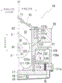
Fig. 2 is a diagram illustrating the arrangement of the electric oil pump 21 and the transmission controller 9(ATCU) of the transmission case 10, wherein fig. 2(a) is an enlarged view of the periphery of the electric oil pump 21 of the transmission case 10 of fig. 1. Fig. 2(b) is a perspective view of the transmission case 10 of fig. 2(a) viewed from the direction of the arrow a-a, and shows an enlarged view of the periphery of the cover portion 126.
As shown in fig. 1, a transmission mechanism 2 of a belt type automatic transmission 1(CVT) for a vehicle includes: a primary pulley 3, a secondary pulley 4, and a power transmission member 5 (belt).
The primary pulley 3 receives a rotational driving force of a driving source (not shown) and rotates about a rotation axis X1 (the axial center of the primary pulley).
The secondary pulley 4 is provided rotatably about a rotation axis X2 (the axial center of the secondary pulley) parallel to the rotation axis X1.
The power transmitting member 5 is wound around the outer periphery of the primary pulley 3 and the outer periphery of the secondary pulley 4. The rotational driving force input to the primary pulley 3 is transmitted to the secondary pulley 4 via the power transmitting member 5.
In the transmission mechanism 2, when the rotational driving force is transmitted from the primary pulley 3 to the secondary pulley 4, the winding radius of the power transmitting member 5 of the primary pulley 3 and the winding radius of the power transmitting member 5 of the secondary pulley 4 are changed.
Thereby, the rotational driving force input to the primary pulley 3 is shifted at a desired speed ratio and transmitted to the secondary pulley 4.
Here, the gear ratio is determined according to the winding radii of the power transmitting members 5 of the primary pulley 3 and the secondary pulley 4. The winding radius is determined by a transmission controller 9(ATCU) of the automatic transmission 1 based on a running state of a vehicle on which the automatic transmission 1 is mounted, and the like.
The rotational driving force transmitted to the secondary pulley 4 is finally transmitted to the driving wheels (not shown) via the gear set 6, the final gear 7, and the differential device 8.
In the present embodiment, the transmission mechanism 2, the gear train 6, and the final gear 7 constitute a transmission mechanism portion.
A horizontal line H1 passing through the rotation axis X1 of the primary pulley 3 is located on the lower side in the vertical direction than a horizontal line H2 passing through the rotation axis X2 of the secondary pulley 4. The rotation axis X1 of the primary pulley 3 and the rotation axis X2 of the secondary pulley 4 are separated in the vertical line direction.
Inside the transmission case 10, the primary pulley 3 is disposed below the secondary pulley 4 in the vertical direction.
Here, the term "vertical line" in the present specification refers to a line parallel to the direction of gravity, and the term "horizontal line" refers to a line perpendicular to the direction of gravity.
The gear train 6 and the final gear 7 are disposed separately from the secondary pulley 4 in the direction of the rotation axis X2 of the secondary pulley 4. In the case of fig. 1, the gear train 6 and the final gear 7 are located on the paper-side front side of the secondary pulley 4.
In the case of fig. 1, the primary pulley 3 and the secondary pulley 4 are located on the deep side of the paper surface inside the transmission case 10. Gear set 6 and final drive gear 7 are located on the front side of the page. The transmission case 10 shown in fig. 1 has a depth both on the near side and the depth side of the drawing, and a drive source not shown is located on the near side of the transmission case 10.
An oil pan 15 is mounted on a lower portion of the transmission case 10. The oil pan 15 closes the opening 16 on the lower side of the transmission case 10, and a third chamber S3 serving as a storage space for the oil OL is formed below the transmission case 10.
The control valve unit 17 is located in the third chamber S3. A control valve unit 17 is also fixed to a lower portion of the transmission case 10, and an oil strainer 18 attached to the control valve unit 17 is located in the oil OL stored in the oil pan 15.
The peripheral wall 11 of the transmission case 10 forms a first chamber S1 serving as a housing space for the transmission mechanism portion inside the transmission case 10.
The first chamber S1 includes a housing space for the transmission mechanism 2, a housing space for the gear train 6 and the final gear 7.
The space in the transmission case 10 is partitioned by a partition wall 111 provided at the lower portion of the peripheral wall 11 into a third chamber S3 on the oil pan 15 side and a first chamber S1 on the transmission mechanism portion (transmission mechanism 2) side.
The peripheral wall 11 has a partition wall portion 12 extending in the vertical line direction in the vicinity of the primary pulley 3. The partition wall portion 12 is positioned on the vehicle front side (radiator RAD) side in a state where the automatic transmission 1 is mounted on the vehicle.
An oil cooler 20 and an electric oil pump 21 are attached to the outer periphery of the partition wall portion 12. In the partition wall portion 12, the electric oil pump 21 is provided on the oil pan side (vertically lower side) of the oil cooler 20.
A vertical line V1 passing through the rotation axis X1 of the primary pulley 3 is located between a vertical line V2 passing through the rotation axis X2 of the secondary pulley 4 and the oil cooler 20, as viewed from the rotation axis X1 direction of the primary pulley 3.
The position of the vertical line V1 passing through the rotation axis X1 of the primary pulley 3 is also between the vertical line V2 passing through the rotation axis X2 of the secondary pulley 4 and the electric oil pump 21, as viewed from the rotation axis X1 direction of the primary pulley 3.
The partition wall portion 12 has: a first wall 121 to which the oil cooler 20 is attached, and a second wall 122 to which the electric oil pump 21 is attached. The second wall 122 is located at the lower side of the first wall 121 in the vertical direction.
The thickness W1 of the first wall 121 in the horizontal line H1 direction is thicker than the thickness W2 of the second wall 122 in the horizontal line H1 direction. A surface 122a of the second wall 122 on the electric oil pump 21 side is disposed at a position closer to the primary pulley shaft 31 than a surface 121a of the first wall 121 on the oil cooler 20 side.
Therefore, the end 21a on the primary pulley 3 side (left side in the drawing) of the electric oil pump 21 in the horizontal line H1 direction is located on the primary pulley 3 side than the end 20a on the primary pulley 3 side (left side in the drawing) of the oil cooler 20 in the horizontal line H1 direction.
The end portion 21a of the electric oil pump 21 and the end portion 20a of the oil cooler 20 are separated in the direction of the horizontal line H1. Further, the center of gravity of the electric oil pump 21 is located in the vicinity of the rotation axis X1 with respect to the center of gravity of the oil cooler 20.
The first wall 121 is provided with a housing 121b of the oil filter 201. The housing portion 121b is provided in an orientation along the vertical line direction. The oil filter 201 is attached to and detached from the housing 121b from the upper side in the vertical direction.
In the present embodiment, the oil OL cooled by the oil cooler 20 is returned to the first chamber S1 side through the oil filter 201.
As described above, the partition wall 111 of the transmission case 10 partitions the space inside the transmission case 10 into the third chamber S3 on the oil pan 15 side and the first chamber S1 on the variator portion (variator 2) side.
The partition wall 111 is provided in a range on the outer side (radiator RAD side) than the surface 121a (outer peripheral surface) of the first wall 121 of the partition wall portion 12 when viewed from the direction of the rotation axis X1.
In the partition wall 111, a region located outside (on the radiator RAD side) the surface 121a (outer peripheral surface) of the first wall 121 becomes a protruding region 111 a.
A wall portion 123 is provided above the extension region 111a in the vertical line direction.
The wall portion 123 extends from the boundary portion of the first wall 121 and the second wall 122 to the outside (radiator RAD side) of the transmission case 10. The wall portion 123 is disposed substantially parallel to the horizontal line H1.
In the transmission case 10, a second chamber S2 (electric oil pump chamber) that houses the electric oil pump 21 is formed between the wall portion 123 in the direction of the vertical line V1 and the protruding region 111 a.
In the second chamber S2, the electric oil pump 21 is fixed to the surface 122a (outer periphery) of the second wall 122. In this state, the electric oil pump 21 is surrounded by the protruding region 111a of the partition wall 111 and the wall portion 123.
The second chamber S2 opens to the outside of the transmission 10 (radially outside the rotation axis X1), and the opening of the second chamber S2 faces the radiator RAD.
The opening of the second chamber S2 is open in the direction of the horizontal line H1, and the opening of the second chamber S2 is sealed by a lid portion 126 that spans the wall portion 123 and the protruding region 111a and is fixed.
A recess 126a is formed in a surface of the lid portion 126 facing the second chamber S2. The transmission controller 9(ATCU) of the automatic transmission 1 is provided in the recess portion 126 a. When the opening of the second chamber S2 is sealed by the lid 126, the transmission controller 9(ATCU) provided on the lid 126 is also housed in the second chamber S2 together with the electric oil pump 21.
As shown in fig. 2(b), a connector 127 electrically connected to the transmission controller 9 is integrally provided on the cover portion 126.
The connector 127 is exposed on the surface (outer surface) of the cover 126, and is located on the deep side of the cover 126 in fig. 1.
The transmission controller 9 is connected to another control device (for example, an engine control unit) mounted in the vehicle via an external wiring connected to the connector 127.
The second chamber S2 has a communication hole 112 provided in the extension region 111a of the partition wall 111. The communication hole 112 penetrates the protruding area 111a in the vertical line direction, and the communication hole 112 communicates the second chamber S2 with the third chamber S3 inside the oil pan 15 at the shortest distance.
A wire harness 128 extending from the transmission controller 9(ATCU) is led out to the oil pan 15 side through the communication hole 112, and then connected to the control valve unit 17.
The transmission controller 9(ATCU) is connected to the control valve unit 17 by a harness 128 having a length shorter than that of a conventional example (see fig. 7) in which the transmission controller 9(ATCU) is provided on the vehicle side.
In the control valve unit 17 are provided: an oil path through which the oil OL flows, a pressure regulating valve that regulates the pressure (oil pressure) of the oil OL, a switching valve that switches the supply destination of the oil OL, and the like.
The transmission controller 9 outputs a drive signal (command) to a solenoid or the like that drives the pressure regulating valve and the switching valve via a wire harness 128. Further, output signals of sensors and the like provided in the transmission case 10 are input to the transmission controller 9 via a harness 128.
An oil passage 129 for connecting the electric oil pump 21 and the control valve unit 17 is provided inside the second wall 122 to which the electric oil pump 21 is fixed.
The oil passage 129 extends linearly in the vertical line direction and connects the control valve unit 17 and the electric oil pump 21 at the shortest distance.
When the electric oil pump 21 is driven, the oil OL in the oil pan 15 is sucked into the oil strainer 18. The oil OL sucked into the oil strainer 18 is supplied to the electric oil pump 21 through an oil passage (not shown) in the control valve unit 17 and an oil passage (not shown) in the second wall 122.
The electric oil pump 21 supplies the sucked oil OL to the control valve unit 17 via the oil passage 129 in the second wall 122 after pressurization.
Further, this oil passage 129 extends in the vertical line direction inside the second wall 122, connecting the control valve unit 17 and the electric oil pump 21 at the shortest distance.
The control valve unit 17 drives a switching valve and a pressure regulating valve based on a command from the transmission controller 9(ATCU) to adjust the hydraulic pressure required for driving and lubricating the automatic transmission 1 (transmission mechanism 2).
Then, the regulated hydraulic pressure (oil) drives a hydraulic drive device (for example, the transmission mechanism 2 or a friction engagement device not shown) provided in the automatic transmission 1, and lubricates a portion that needs to be lubricated.
Next, the assembly sequence of the electric oil pump 21 and the transmission controller 9 of the automatic transmission 1 having such a configuration will be described.
In the transmission case 10, the second chamber S2 opens on the outer surface of the peripheral wall 11 (the surface radially outward of the rotation axis X1).
First, the electric oil pump 21 is inserted into the second chamber S2 from the opening of the second chamber S2, and then the electric oil pump 21 is fixed to the surface 122a of the second wall 122 exposed at the depth of the second chamber S2 by bolts (not shown).
A lid 126 is prepared in a state where the transmission controller 9(ATCU) is provided in the recess 126a, and the distal end side of the wire harness 128 drawn out from the transmission controller 9 is inserted into the communication hole 112.
The wire harness 128 inserted into the communication hole 112 is led out to the third chamber S3 side, and then connected to a connector (not shown) provided in the control valve unit 17.
The control valve unit 17 to which the wire harness 128 is connected is fixed to the lower portion of the transmission case 10 with bolts.
The opening of the second chamber S2 is closed by the surface of the cover 126 on the transmission controller 9 side, and the peripheral edge portion of the cover 126 is fixed to the protruding region 111a and the wall portion 123 of the transmission case 10 with bolts (not shown). At this time, the wire harness 128 is accommodated in the gap in the second chamber S2.
Here, the second chamber S2 is a space formed independently from the first chamber S1 and the third chamber S3. The second chamber S2 is partitioned from the first chamber S1 by the second wall 122 of the transmission case 10, and is partitioned from the third chamber S3 by the protruding region 111a of the partition wall 111.
Therefore, the second chamber S2 is partitioned from the first chamber S1 that houses the speed change mechanism (rotating body) and the third chamber S3 that stores oil.
The extension region 111a is provided with a communication hole 112 that communicates the second chamber S2 with the third chamber S3, but the communication hole 112 is narrowed in its opening range by the wire harness 128 provided in the communication hole 112.
Further, unlike the first chamber S1, no rotating body is provided in the third chamber S3 to splash up the oil. The second chamber S2 is disposed above the third chamber S3 in the vertical direction.
Therefore, the working oil (oil) in the third chamber S3 is difficult to flow into the second chamber S2, and the transmission controller 9 disposed in the second chamber S2 is not normally exposed to a large amount of high-temperature working oil (oil).
Further, the communication hole 112 penetrates the protruding region 111a in the vertical line direction, and the communication hole 112 communicates the second chamber S2 and the third chamber S3 at the shortest distance.
Therefore, the entire length of the wire harness 128 can be shortened, and thus the resistance of the wire harness 128 can be reduced. It is possible to suppress the occurrence of an error in a signal (sensor signal, command) accessed via the wire harness 128.
In addition, the overall length of the wire harness 128 is shortened, which can reduce costs accordingly.
Further, since the transmission controller 9 is mounted on the lid portion 126, the electric oil pump 21 is disposed in the second chamber S2, and then the opening of the second chamber S2 is closed by the lid portion 126, whereby the transmission controller 9 is also disposed at the same time.
Therefore, since the electric oil pump 21 and the transmission controller 9 can be provided substantially simultaneously, the assembly work thereof is easy.
Further, since the number of necessary parts is reduced as compared with the case where the electric oil pump 21 and the transmission controller 9 are separately provided, cost reduction associated with reduction in the number of parts can be achieved. In addition, since the space required for the arrangement of the electric oil pump 21 and the transmission controller 9 is reduced, a space-saving effect can be expected.
Next, the operation of the automatic transmission 1 having such a structure will be described.
In the automatic transmission 1, a second chamber S2 (motor oil pump chamber) provided with the transmission controller 9 and a first chamber S1 (transmission mechanism chamber) provided with the rotary elements (transmission mechanism 2, final gear 7) are divided by a second wall 122.
Therefore, the high-temperature oil OL splashed by the rotary elements in the first chamber S1 does not directly flow into the second chamber S2 because the second wall 122 is interposed between the first chamber S1 and the second chamber S2.
Therefore, the transmission controller 9 disposed in the second chamber S2 does not directly contact the high-temperature oil OL in the first chamber S1, and the transmission controller 9 is not exposed to a large amount of the high-temperature oil OL.
The second chamber S2 communicates with the third chamber S3 via the communication hole 112, but the third chamber S3 is a housing chamber (control valve unit chamber) of the control valve unit 17 and is not provided with a rotary element that splashes up the oil OL like the first chamber.
Therefore, the oil OL of the third chamber is hard to flow into the second chamber S2 located at the upper side of the third chamber S3 in the vertical line direction. Therefore, the transmission controller 9 disposed within the second chamber S2 is not exposed to the oil OL flowing in from the third chamber S3 side.
As described above, the automatic transmission 1 (continuously variable transmission) of the embodiment has the following configuration.
(1) Comprising: a first chamber S1 (transmission chamber) in which the transmission mechanism is disposed, a second chamber S2 (electric oil pump chamber) in which the electric oil pump 21 is disposed, and the transmission controller 9 disposed in the second chamber S2. The first chamber S1 and the second chamber S2 are divided (divided) by the partition wall portion 12.
With this configuration, the transmission controller 9 can be disposed in the second chamber S2 (electric oil pump chamber) that is separated from the first chamber S1 (transmission mechanism chamber), and thus the transmission controller 9 can be prevented from being exposed to a large amount of high-temperature hydraulic oil.
Further, the automatic transmission 1 has the following structure.
(2) There is a third chamber S3 (control valve unit chamber) in which the control valve unit 17 is disposed.
There is a communication hole 112 (hole) that communicates the second chamber S2 and the third chamber S3.
The third chamber S3 is located directly below the second chamber S2 in the vertical direction.
The transmission controller 9 and the control valve unit 17 are connected via a wire harness 128 inserted through the communication hole 112.
When thus configured, since the communication hole 112 communicates the second chamber S2 and the third chamber S3 at the shortest distance, the length of the wire harness 128 connecting the transmission controller 9 and the control valve unit 17 can be shortened.
When the length of the wire harness 128 is shortened, it is possible to expect a reduction in the resistance and/or a reduction in the cost of the wire harness 128.
Further, the automatic transmission 1 (continuously variable transmission) has the following configuration.
(3) Comprising: the transmission control device includes a first chamber S1 in which a transmission mechanism is disposed, a second chamber S2 in which a transmission controller 9 is disposed, and a lid 126 constituting at least a part of the second chamber S2, and the transmission controller 9 is mounted on the lid 126.
When the transmission controller 9 is mounted on the lid portion 126, the transmission controller 9 is also provided in the second chamber S2 when the lid portion 126 is assembled to the transmission case 10 to form the second chamber S2.
Therefore, the transmission controller 9 can be assembled more easily than if the transmission controller 9 were provided separately from the cover 126.
In addition, when the transmission controller 9 is provided separately from the cover portion 126, it is necessary to separately prepare a dedicated component for providing the transmission controller 9. Mounting the transmission controller 9 on the lid portion 126 eliminates the need for separately providing a component for installing the transmission controller 9. This can prevent an increase in the number of components, and can provide an effect of reducing the number of components.
Further, since the transmission controller 9 is provided by utilizing the space in the second chamber S2 that houses the electric oil pump 21, the effect of saving space can be achieved as compared with the case where the transmission controller 9 is provided outside the second chamber S2.
In the embodiment, a case is exemplified in which a concave portion 126a is provided on a surface of the lid portion 126 facing the second chamber S2, and the transmission controller 9 is provided in the concave portion 126 a.
When the recess 126a is not provided in the cover 126, the transmission controller 9 may be assembled with the cover 126 by fixing the transmission controller 9 to the surface of the cover 126 facing the second chamber S2.
Further, the automatic transmission 1 (continuously variable transmission) has the following configuration.
(4) There is a connector 127 which is connected to the transmission controller 9. Connector 127 is mounted on lid 126 and exposed on the surface of transmission case 10.
In the case of such a configuration, by mounting the connector 127 on the cover portion 126, the assembly of the transmission controller 9 and the connector 127 is completed at the time when the attachment of the cover portion 126 to the transmission case 10 side is completed.
Therefore, when the connector 127 is provided separately from the cover 126, it is necessary to separately prepare a dedicated component for providing the connector 127. When the connector 127 is mounted on the lid portion 126, it is not necessary to separately prepare a part for installing the connector 127. This can prevent an increase in the number of components, and can provide an effect of reducing the number of components.
Further, since the connector 127 is provided on the cover portion 126, a space for installation can be suppressed as compared with a case where the connector 127 is provided on another portion of the transmission case 10. Thus, a space-saving effect can be achieved.
In the embodiment, the case where the connector 127 is provided integrally with the cover 126 is exemplified. The connector 127 may be formed separately from the cover 126 and fixed to the cover 126.
The invention of the present application may also be specified as a method of manufacturing the automatic transmission 1 (continuously variable transmission).
That is, (5) a method of manufacturing an automatic transmission 1 having: the method for manufacturing the automatic transmission 1 includes disposing the first chamber S1 in which the transmission mechanism is disposed, disposing the second chamber S2 in which the transmission controller 9 and the electric oil pump 21 are disposed, and disposing the lid portion 126 constituting at least a part of the second chamber S2, and is characterized in that the lid portion 126 in which the transmission controller 9 is mounted after disposing the electric oil pump 21 in the second chamber S2.
With this configuration, when the electric oil pump 21 and the transmission controller 9 are mounted substantially simultaneously, the electric oil pump 21 and the transmission controller 9 can be easily assembled by performing the mounting operation in the following order.
(a) The electric oil pump 21 is first installed in the second chamber S2.
(b) The lid portion 126 on which the transmission controller 9 is mounted is attached to the transmission case 10 side, and closes the opening of the second chamber S2.
The automatic transmission 1 of the embodiment has the following configuration.
(6) The automatic transmission 1 includes: an oil cooler 20, an electric oil pump 21, and a transmission mechanism 2.
The transmission mechanism 2 includes: a primary pulley 3, a secondary pulley 4, and a power transmission member 5 wound around the primary pulley 3 and the secondary pulley 4.
A vertical line V1 passing through the axial center (the rotation axis X1) of the primary pulley 3 is located between a vertical line V2 passing through the axial center (the rotation axis X2) of the secondary pulley 4 and the oil cooler 20, as viewed from the drive source (not shown) side in the rotation axis X1 direction.
A vertical line V1 passing through the axial center (rotation axis X1) of the primary pulley 3 is located between a vertical line V2 passing through the axial center (rotation axis X2) of the secondary pulley 4 and the electric oil pump 21. The end 21a of the electric oil pump 21 on the primary pulley 3 side is disposed at a position closer to the primary pulley 3 than the end 20a of the oil cooler 20 on the primary pulley 3 side.
In the automatic transmission 1(CVT), resonance of the drive source and the CVT (power plant resonance) occurs.
The present inventors have focused on the following points.
(a) The closer the installation location of the electric oil pump is to the node of the power plant resonance (the location where the amplitude is small), the lower the sound power level, the more advantageous the sound vibration.
(b) The farther the electric oil pump is installed from the node (where the amplitude is small) where the power plant resonates, the worse (worse) the sound vibration performance.
(c) In a CVT, the node at which the power plant resonates is the primary pulley shaft 31.
As described above, the end 21a of the electric oil pump 21 on the primary pulley 3 side is disposed closer to the primary pulley 3 than the end 20a of the oil cooler 20 on the primary pulley 3 side, whereby the electric oil pump 21 is disposed closer to the primary pulley shaft 31.
Thus, the amplitude of the electric oil pump 21 when vibrated by the power plant resonance is smaller than that in the automatic transmission 1X of the conventional example shown in fig. 7.
Thus, the degree of noise (sound power level) generated by the vibration is reduced.
The automatic transmission 1 of the embodiment has the following configuration.
(7) A first wall 121 is provided between a vertical line V1 passing through the axial center (the rotation axis X1) of the primary pulley 3 and the oil cooler 20.
A second wall 122 is provided between the electric oil pump 21 and a vertical line V1 passing through the axial center (the rotation axis X1) of the primary pulley 3.
The surface 122a of the second wall 122 on the electric oil pump 21 side is disposed at a position closer to the primary pulley 3 than the surface 121a of the first wall 121 on the oil cooler 20 side.
With this configuration, the peripheral wall 11 of the transmission case 10 is shaped such that the second wall 122 is located closer to the primary pulley 3 than the first wall 121.
By designing the transmission case 10 (the peripheral wall 11) such that the second wall 122 is offset toward the primary pulley 3 side more than the first wall 121 in this way, the end portion 21a of the electric oil pump 21 can be brought close to the primary pulley 3.
The automatic transmission 1 of the embodiment has the following configuration.
(8) The oil OL is supplied from the electric oil pump 21 to the control valve unit 17 via an oil passage 129 formed in the second wall 122.
When the electric oil pump is attached to the outer periphery of the transmission, the hydraulic oil is generally supplied from the electric oil pump to the control valve unit using a dedicated pipe provided separately from the transmission.
As described above, by providing the oil passage 129 in the second wall 122 of the transmission 10, the hydraulic pressure can be supplied from the electric oil pump 21 to the control valve unit 17 by using the oil passage 129 in the second wall 122, instead of using a dedicated pipe provided separately from the transmission.
By providing the oil passage 129 by the second wall 122, the number of parts can be reduced as compared with the case where a dedicated pipe provided separately from the transmission case is used. Further, the overall length of the oil passage connecting the electric oil pump 21 and the control valve unit 17 can be shortened.
Hereinafter, the effects and the features of the present invention will be described as required.
(9) A horizontal line H1 passing through the axial center (rotation axis X1) of the primary pulley 3 is located below a horizontal line H2 passing through the axial center (rotation axis X2) of the secondary pulley 4 in the vertical direction.
The electric oil pump 21 is located below the oil cooler 20 in the vertical line direction.
The electrical oil pump 21 can be brought close to the primary pulley 3 by determining the vertical relationship between the electrical oil pump 21 and the oil cooler 20 from the vertical relationship in the vertical line direction of the two pulleys (the primary pulley 3, the secondary pulley 4).
(10) The electric oil pump 21 is located between the oil cooler 20 and the control valve unit 17 as viewed from the direction of the rotation axis X1.
The oil is supplied from the electric oil pump 21 to the control valve unit 17 through an oil passage 129 formed in the second wall 122.
Since the oil passage 129 can be shortened, a decrease in strength of the transmission case 10 can be suppressed.
(11) The automatic transmission 1 is mounted on a vehicle. The oil cooler 20 and the electric oil pump 21 are disposed between a radiator RAD mounted on the vehicle and a vertical line V1 passing through an axial center (a rotation axis X1) of the primary pulley 3 when viewed from the rotation axis X1 direction.
The oil cooler 20 and the electric oil pump 21 are disposed on the front side of the vehicle. Since the electric oil pump 21 can be disposed by utilizing the clearance between the radiator RAD and the transmission 10, it is not necessary to change the layout design on the vehicle side when the electric oil pump 21 is provided on the outer periphery (surface) of the transmission 10.
(12) The electric oil pump 21 is disposed in a second chamber S2 (electric oil pump chamber) including the second wall 122.
A transmission controller 9(ATCU) is disposed in the second chamber S2.
When the vehicle on which the automatic transmission 1 is mounted is a hybrid vehicle including both an engine and a motor as drive sources, an MCU (motor controller) is further disposed in the second compartment S2.
The first chamber S1 that houses the pulleys (primary pulley 3, secondary pulley 4) is in an environment exposed to a large amount of working oil (oil). By placing the controllers (transmission controller 9, motor controller) in the second chamber S2, which is a chamber divided from the first chamber S1, it is possible to prevent the controllers (transmission controller 9, motor controller) from being exposed to a large amount of high-temperature hydraulic oil.
(13) The oil filter 201 is disposed between the oil cooler 20 and a vertical line V1 passing through the axial center (the rotation axis X1) of the primary pulley 3 when viewed from the rotation axis X1 direction.
The oil filter 201 is disposed in the first wall 121 to which the oil cooler 20 is attached.
The thickness W1 in the horizontal line H1 direction of the first wall 121 to which the oil cooler 20 is attached is thicker than the thickness W2 in the horizontal line H1 direction of the second wall 122 to which the electric oil pump 21 is attached.
The thickness W1 in the horizontal line H1 direction of the first wall 121 and the thickness W2 in the horizontal line H1 direction of the second wall 122 are made different so that the distance from the primary pulley shaft 31 to the oil cooler 20 is longer than the distance from the primary pulley shaft 31 to the electric oil pump 21.
That is, the thicknesses of the first wall 121 and the second wall 122 are made different, so that the oil cooler 20 is disposed farther from the primary pulley shaft 31 than the electric oil pump.
This ensures a space for disposing the oil filter 201 in the first wall 121.
Thereby, the oil filter 201 can be disposed in the vicinity of the oil cooler 20. When the oil filter 201 and the oil cooler 20 are separately disposed, a long pipe for communicating the oil filter 201 and the oil cooler 20 needs to be separately prepared.
By disposing the oil filter 201 in the vicinity of the oil cooler 20, it is not necessary to separately prepare a long pipe, and therefore the number of parts can be reduced.
Further, the electric oil pump 21 having a larger mass than the oil cooler 20 can be disposed closer to the node (primary pulley shaft 31) of the power plant resonance.
As a result, the amplitude of the electric oil pump 21 that vibrates due to the power plant resonance decreases, and the acoustic power level of the noise generated by the vibrating electric oil pump 21 decreases.
(14) A partition wall 111 (third wall) that partitions the second chamber S2 and the third chamber S3 is provided between the second chamber S2 (chamber in which the electric oil pump 21 and the transmission controller 9 are housed) and the third chamber S3 (chamber in which the control valve unit 17 is disposed).
In the projecting region 111a of the partition wall 111, a communication hole 112 is provided for communicating the second chamber S2 with the third chamber S3.
The communication hole 112 is formed linearly along a vertical line to communicate the second chamber S2 and the third chamber S3 at the shortest distance.
The transmission controller 9 and the control valve unit 17 are connected to each other by a wire harness 128 inserted through the communication hole 112.
The harness 128 connecting the transmission controller 9 and the control valve unit 17 can be shortened, and the resistance and cost of the harness 128 can be reduced.
Fig. 3 and 4 are diagrams illustrating modified examples of the arrangement of the transmission controller 9 of the transmission 10.
In the above-described embodiment, the case where the second chamber S2 (electric oil pump chamber) for housing the electric oil pump 21 is formed by the second wall 122 of the partition wall portion 12, the wall portion 123, the protruding region 111a, and the lid portion 126 is exemplified.
As in the automatic transmission 1A shown in fig. 3, the second chamber S2 may be formed only by the lid portion 126A attached to the outer periphery of the second wall 122 by using the lid portion 126A in which the depth of the recess portion 126A in the horizontal line H1 direction is increased.
In the above-described embodiment, the transmission controller 9 is provided in the recess 126a of the lid 126 in the second chamber S2 as an example.
As in the automatic transmission 1B shown in fig. 4, the transmission controller 9 may be provided on the upper side 111B of the extension region 111a in the vertical direction.
In this case, the transmission controller 9 can be disposed closer to the control valve unit 17 than in the case where the transmission controller 9 is disposed in the recess 126a of the cover 126.
This can further shorten the overall length of the wire harness 128, and thus can suppress the occurrence of signal (sensor signal, command) errors accessed via the wire harness 128.
In the above-described embodiment, the case where the second chamber S2 is an electric oil pump chamber that houses the electric oil pump 21, and the transmission controller 9(ATCU) is housed in the electric oil pump chamber is exemplified.
The place where the transmission controller 9 is provided is not limited to the second chamber S2. For example, the storage chamber may be a storage chamber for storing other components provided in the automatic transmission such as the control valve unit 17 and the oil filter 201.
Fig. 5 is a diagram illustrating a modification of the arrangement of the transmission controller 9 of the transmission case 10, and is a diagram illustrating a case where the transmission controller 9 is arranged in the third chamber S3 (control valve unit chamber).
As shown in fig. 5, in the automatic transmission 1C, a recess 151 for housing the transmission controller 9 is provided in the oil pan 15.
The transmission controller 9 is disposed in the third chamber S3 (control valve unit chamber) in a state of being disposed in the recess 151. The transmission controller 9 is housed in the recess 151 and prevented from being displaced from the oil pan 15.
That is, the automatic transmission 1C has the following structure.
(15) Comprising: the first chamber S1 in which the speed change mechanism is disposed, the second chamber S2 in which the electric oil pump 21 is disposed, and the third chamber S3 in which the control valve unit 17 is disposed. The third chamber S3 is formed inside an oil pan 15 (cover) attached to the lower portion of the transmission case 10. The transmission controller 9 is provided in an oil pan 15.
In the case of such a configuration, since the transmission controller 9 is provided in the existing oil pan 15, it is not necessary to perform a large design change around the oil pan 15 in order to provide the transmission controller 9.
In particular, since the transmission controller 9 is provided in the recess 151 provided in the oil pan 15, no additional component is required when the transmission controller 9 is provided in the existing oil pan 15.
Therefore, the transmission controller 9 and the control valve unit 17 can be connected with a short distance while appropriately preventing an increase in manufacturing cost due to an increase in the number of parts.
Further, since the transmission controller 9 is disposed closer to the control valve unit 17, the entire length of the wire harness 128 can be further shortened.
This can reduce the resistance of the wire harness 128, and can suppress the occurrence of errors in signals (sensor signals, commands) accessed via the wire harness 128. In addition, since the entire length of the wire harness 128 is shortened, the cost can be reduced accordingly.
In the case of the automatic transmission 1C of fig. 5, the above-described method for manufacturing the automatic transmission can be specified as follows.
(16) The automatic transmission includes: the first chamber S1 (variator chamber) in which the variator is disposed, the second chamber S2 in which the electric oil pump 21 is disposed, and the third chamber S3 in which the control valve unit 17 is disposed. The third chamber S3 is formed inside an oil pan 15 fixed to a lower portion of the transmission case 10. The transmission controller 9 is provided to the oil pan 15.
The automatic transmission 1C is manufactured by connecting the wire harness 128 extending from the transmission controller 9 to the control valve unit 17, fixing the control valve unit 17 to the lower portion of the transmission case 10 in the third chamber S3, attaching the oil pan 15 provided with the transmission controller 9 to the transmission case 10, and blocking the opening 16 of the lower portion of the transmission case 10 with the oil pan 15 to form a third chamber S3.
With this configuration, when the control valve unit 17 (other components) and the transmission controller 9 are mounted at the same time, assembly is facilitated by the rear-mounted oil pan 15 (cover).
When the transmission controller 9 is provided, no additional parts are required, and therefore, an increase in manufacturing cost can be appropriately suppressed.
Fig. 6 is a diagram illustrating a modification of the arrangement of the transmission case 10 of the transmission controller 9, and is a diagram illustrating a case of the automatic transmission 1D in which the oil cooler 20 is provided above the partition wall portion 12 in the vertical direction.
An oil cooler 20 is provided in an upper portion of a first wall 121 in a vertical direction in a partition wall portion 12 of a transmission case 10 of an automatic transmission 1D.
The thickness of the first wall 121 in the direction of the horizontal line H2 is thicker than the second wall 122 on the oil pan 15 side.
The first wall 121 is provided with a housing 121c for the oil filter 201. The housing portion 121c is provided in an orientation along the horizontal line H2. The oil filter 201 is detachable from the housing section 121c from the vehicle front side in the horizontal line H2 direction.
In the case of the automatic transmission 1D, the oil OL cooled by the oil cooler 20 is also returned to the first chamber S1 side through the oil filter 201.
A lid 126 for closing the opening of the housing 121c is attached to the front surface of the partition wall 12 on the vehicle front side.
The cover portion 126 has a recess 126a on a surface facing the partition wall portion 12, and the transmission controller 9 is accommodated in the recess 126 a.
A connector (not shown) is provided on the surface of the cover 126, and the transmission controller 9 is connected to another control device (for example, an engine control unit) mounted on the vehicle via an external wiring connected to the connector 127.
A cover 126 is disposed across the first wall 121 and the second wall 122. The region between the partition wall portion 12 and the recess 126a of the lid portion 126 serves as a filter chamber (fourth chamber S4) for partitioning the oil filter 201 from the outside.
In a region of the second wall 122 facing the lid portion 126, a communication hole 130 is opened to communicate the fourth chamber (filter chamber) S4 and the third chamber S3.
The wire harness 128 extending from the transmission controller 9 is led out into the third chamber S3 through the communication hole 130, and is connected to the control valve unit 17 in the third chamber S3.
In the automatic transmission 1D, the oil filter 201 is disposed in the fourth chamber S4, and the lid 126, which is a component related to the oil cooler 20, serves as a lid of the fourth chamber S4.
By making the oil cooler 20a little farther than the electric oil pump 21, a space for disposing the oil filter 201 can be secured. Thereby, the oil filter 201 can be disposed in the vicinity of the oil cooler 20. Therefore, a long pipe for communicating the oil filter 201 and the oil cooler 20 is not required, and the number of parts can be reduced.
As described above, the automatic transmission 1D has the following structure.
(17) Comprising: the transmission controller 9 is mounted on the lid 126, with the first chamber S1 in which the transmission mechanism is disposed, the second chamber S2 in which the electric oil pump 21 is disposed, the fourth chamber S4 which becomes a filter chamber of the oil filter 201 of the oil cooler 20, and the lid 126 which constitutes at least a part of the fourth chamber S4.
In the case of such a configuration, since the transmission controller 9 is provided in the lid portion 126 that partitions the existing filter chamber (housing chamber) of the oil filter 201, no additional parts are required when the transmission controller 9 is provided in the fourth chamber S4 that is the housing chamber of the oil filter 201. Therefore, an increase in cost for providing the transmission controller 9 can be appropriately suppressed.
In this case, the above-described method for manufacturing the automatic transmission can be specified as follows.
(18) The automatic transmission includes: the first chamber S1 (transmission chamber) in which the transmission mechanism is disposed, the second chamber S2 in which the electric oil pump 21 is disposed, the fourth chamber S4 which is a storage chamber of the oil filter 201, and the lid 126 which constitutes at least a part of the fourth chamber S4. The transmission controller 9 is mounted on the lid portion 126.
The automatic transmission is manufactured by disposing the oil filter 201 in the fourth chamber S4 and then attaching the lid 126 provided with the transmission controller 9.
With this configuration, when the oil filter 201 (other components) and the transmission controller 9 are mounted at the same time, the lid 126 is mounted at the rear, thereby facilitating assembly.
The transmission controller 9 and/or the connector are preferably mounted on the components on the side of the oil cooler 20, because the number of components can be reduced.
The embodiments of the invention of the present application have been described above, but the invention of the present application is not limited to the embodiments shown in the above. The present invention can be modified as appropriate within the scope of the technical idea of the present invention.
Claims (1)
1. An automatic transmission characterized by comprising:
a first chamber provided with a speed change mechanism;
a second chamber provided with an electric oil pump and independent from the first chamber;
a transmission controller disposed within the second chamber;
a third chamber configured to control the valve unit and independent from the second chamber,
the third chamber is disposed in a range extending from below the first chamber to below the second chamber,
the transmission controller and the control valve unit are connected via a wire harness inserted into a hole that communicates the second chamber and the third chamber, and not via the first chamber,
the transmission mechanism is driven based on a command of the transmission controller,
the control valve unit is supplied with oil from the electric oil pump via an oil passage formed in a second wall of a partition wall portion that partitions the first chamber and the second chamber.
Priority Applications (1)
| Application Number | Priority Date | Filing Date | Title |
|---|---|---|---|
| CN201910782323.3A CN110513460A (en) | 2017-07-14 | 2018-07-13 | Automatic transmission |
Applications Claiming Priority (2)
| Application Number | Priority Date | Filing Date | Title |
|---|---|---|---|
| JP2017138493A JP6925897B2 (en) | 2017-07-14 | 2017-07-14 | Automatic transmission |
| JP2017-138493 | 2017-07-14 |
Related Child Applications (1)
| Application Number | Title | Priority Date | Filing Date |
|---|---|---|---|
| CN201910782323.3A Division CN110513460A (en) | 2017-07-14 | 2018-07-13 | Automatic transmission |
Publications (2)
| Publication Number | Publication Date |
|---|---|
| CN109253220A CN109253220A (en) | 2019-01-22 |
| CN109253220B true CN109253220B (en) | 2022-03-29 |
Family
ID=65049223
Family Applications (2)
| Application Number | Title | Priority Date | Filing Date |
|---|---|---|---|
| CN201910782323.3A Pending CN110513460A (en) | 2017-07-14 | 2018-07-13 | Automatic transmission |
| CN201810769462.8A Active CN109253220B (en) | 2017-07-14 | 2018-07-13 | Automatic transmission |
Family Applications Before (1)
| Application Number | Title | Priority Date | Filing Date |
|---|---|---|---|
| CN201910782323.3A Pending CN110513460A (en) | 2017-07-14 | 2018-07-13 | Automatic transmission |
Country Status (3)
| Country | Link |
|---|---|
| JP (1) | JP6925897B2 (en) |
| KR (1) | KR20190008093A (en) |
| CN (2) | CN110513460A (en) |
Families Citing this family (2)
| Publication number | Priority date | Publication date | Assignee | Title |
|---|---|---|---|---|
| WO2021015205A1 (en) * | 2019-07-25 | 2021-01-28 | ジヤトコ株式会社 | Power transmission device |
| CN115803546A (en) * | 2020-07-09 | 2023-03-14 | 加特可株式会社 | Cover-shaped part |
Citations (4)
| Publication number | Priority date | Publication date | Assignee | Title |
|---|---|---|---|---|
| CN1205062A (en) * | 1996-02-10 | 1999-01-13 | 奥迪股份公司 | Automatic electrohydraulically controlled transmission |
| JP2001260674A (en) * | 2000-03-22 | 2001-09-26 | Jatco Transtechnology Ltd | Transmission unit |
| CN101586644A (en) * | 2008-05-21 | 2009-11-25 | 本田技研工业株式会社 | Transmission |
| JP2013148203A (en) * | 2012-01-23 | 2013-08-01 | Denso Corp | Control device of automatic transmission |
Family Cites Families (9)
| Publication number | Priority date | Publication date | Assignee | Title |
|---|---|---|---|---|
| JPH01312252A (en) * | 1988-06-08 | 1989-12-18 | Jatco Corp | Electronically controlled automatic transmission |
| JPH0728261U (en) * | 1993-10-29 | 1995-05-23 | 日野自動車工業株式会社 | Transmission oil cooling system |
| JP3005528B1 (en) * | 1998-07-24 | 2000-01-31 | 本田技研工業株式会社 | Transmission for vehicles |
| JP2006097767A (en) * | 2004-09-29 | 2006-04-13 | Jatco Ltd | Oil pump configuration for automatic transmission |
| JP2007255369A (en) * | 2006-03-24 | 2007-10-04 | Jatco Ltd | Oil pump structure of transmission |
| JP2009174668A (en) | 2008-01-28 | 2009-08-06 | Hitachi Ltd | Electronic control device |
| JP5331847B2 (en) * | 2011-06-20 | 2013-10-30 | ジヤトコ株式会社 | Control device for automatic transmission |
| JP5761086B2 (en) * | 2012-03-12 | 2015-08-12 | トヨタ自動車株式会社 | vehicle |
| JP2016053309A (en) * | 2014-09-03 | 2016-04-14 | 日立オートモティブシステムズ株式会社 | Electric oil pump combined with automatic transmission |
-
2017
- 2017-07-14 JP JP2017138493A patent/JP6925897B2/en active Active
-
2018
- 2018-06-29 KR KR1020180075186A patent/KR20190008093A/en not_active Application Discontinuation
- 2018-07-13 CN CN201910782323.3A patent/CN110513460A/en active Pending
- 2018-07-13 CN CN201810769462.8A patent/CN109253220B/en active Active
Patent Citations (4)
| Publication number | Priority date | Publication date | Assignee | Title |
|---|---|---|---|---|
| CN1205062A (en) * | 1996-02-10 | 1999-01-13 | 奥迪股份公司 | Automatic electrohydraulically controlled transmission |
| JP2001260674A (en) * | 2000-03-22 | 2001-09-26 | Jatco Transtechnology Ltd | Transmission unit |
| CN101586644A (en) * | 2008-05-21 | 2009-11-25 | 本田技研工业株式会社 | Transmission |
| JP2013148203A (en) * | 2012-01-23 | 2013-08-01 | Denso Corp | Control device of automatic transmission |
Also Published As
| Publication number | Publication date |
|---|---|
| CN109253220A (en) | 2019-01-22 |
| JP6925897B2 (en) | 2021-08-25 |
| CN110513460A (en) | 2019-11-29 |
| JP2019019887A (en) | 2019-02-07 |
| KR20190008093A (en) | 2019-01-23 |
Similar Documents
| Publication | Publication Date | Title |
|---|---|---|
| EP1637778B1 (en) | Oil separating structure of automatic transmission | |
| JP5707656B2 (en) | Vehicle drive device | |
| KR100864627B1 (en) | Hydraulic circuit device and hybrid drive apparatus using the same | |
| JP5041249B2 (en) | Vehicle drive device | |
| US20060060424A1 (en) | Baffle plate | |
| CN109253220B (en) | Automatic transmission | |
| CN109253222B (en) | Automatic transmission | |
| US11193491B2 (en) | Hydraulic power unit | |
| US10967845B2 (en) | Drive-force transmitting apparatus for vehicle | |
| CN109253221B (en) | Automatic transmission | |
| US8100229B2 (en) | Oil flow passage arrangement of automatic transmission | |
| WO2023182455A1 (en) | Power transmission device | |
| JP7069244B2 (en) | Lubrication structure of vehicle power transmission device | |
| WO2023182447A1 (en) | Power transmission device | |
| WO2023182451A1 (en) | Power transmission device | |
| WO2023182453A1 (en) | Power transmission device | |
| WO2023182450A1 (en) | Power transmission device | |
| JP2019124341A (en) | Power transmission device | |
| WO2023182444A1 (en) | Power transmission device | |
| US11572943B2 (en) | Housing member for power transmission device | |
| JP2023141341A (en) | power transmission device | |
| WO2023182456A1 (en) | Power transmission device | |
| JP2020112246A (en) | Lubrication structure for hybrid vehicle driving device | |
| JP6089720B2 (en) | Hydraulic control device | |
| JP2018141536A (en) | Lubrication device for power transmission device |
Legal Events
| Date | Code | Title | Description |
|---|---|---|---|
| PB01 | Publication | ||
| PB01 | Publication | ||
| SE01 | Entry into force of request for substantive examination | ||
| SE01 | Entry into force of request for substantive examination | ||
| GR01 | Patent grant | ||
| GR01 | Patent grant |