WO2023182454A1 - Power transmission device - Google Patents
Power transmission device Download PDFInfo
- Publication number
- WO2023182454A1 WO2023182454A1 PCT/JP2023/011617 JP2023011617W WO2023182454A1 WO 2023182454 A1 WO2023182454 A1 WO 2023182454A1 JP 2023011617 W JP2023011617 W JP 2023011617W WO 2023182454 A1 WO2023182454 A1 WO 2023182454A1
- Authority
- WO
- WIPO (PCT)
- Prior art keywords
- power transmission
- motor
- rotation axis
- control valve
- boss portion
- Prior art date
Links
- 230000005540 biological transmission Effects 0.000 title claims abstract description 68
- 230000007246 mechanism Effects 0.000 claims abstract description 36
- 230000001105 regulatory effect Effects 0.000 claims description 22
- 230000002093 peripheral effect Effects 0.000 claims description 21
- 238000005192 partition Methods 0.000 claims 2
- 210000000078 claw Anatomy 0.000 description 28
- 238000010586 diagram Methods 0.000 description 13
- 238000009434 installation Methods 0.000 description 10
- 238000006073 displacement reaction Methods 0.000 description 7
- 230000005484 gravity Effects 0.000 description 4
- 230000012447 hatching Effects 0.000 description 3
- 230000037431 insertion Effects 0.000 description 3
- 238000003780 insertion Methods 0.000 description 3
- 238000001816 cooling Methods 0.000 description 1
- 230000002452 interceptive effect Effects 0.000 description 1
- 230000001050 lubricating effect Effects 0.000 description 1
Images


Classifications
-
- F—MECHANICAL ENGINEERING; LIGHTING; HEATING; WEAPONS; BLASTING
- F04—POSITIVE - DISPLACEMENT MACHINES FOR LIQUIDS; PUMPS FOR LIQUIDS OR ELASTIC FLUIDS
- F04B—POSITIVE-DISPLACEMENT MACHINES FOR LIQUIDS; PUMPS
- F04B53/00—Component parts, details or accessories not provided for in, or of interest apart from, groups F04B1/00 - F04B23/00 or F04B39/00 - F04B47/00
-
- F—MECHANICAL ENGINEERING; LIGHTING; HEATING; WEAPONS; BLASTING
- F16—ENGINEERING ELEMENTS AND UNITS; GENERAL MEASURES FOR PRODUCING AND MAINTAINING EFFECTIVE FUNCTIONING OF MACHINES OR INSTALLATIONS; THERMAL INSULATION IN GENERAL
- F16H—GEARING
- F16H57/00—General details of gearing
- F16H57/02—Gearboxes; Mounting gearing therein
-
- F—MECHANICAL ENGINEERING; LIGHTING; HEATING; WEAPONS; BLASTING
- F16—ENGINEERING ELEMENTS AND UNITS; GENERAL MEASURES FOR PRODUCING AND MAINTAINING EFFECTIVE FUNCTIONING OF MACHINES OR INSTALLATIONS; THERMAL INSULATION IN GENERAL
- F16H—GEARING
- F16H61/00—Control functions within control units of change-speed- or reversing-gearings for conveying rotary motion ; Control of exclusively fluid gearing, friction gearing, gearings with endless flexible members or other particular types of gearing
Abstract
[Problem] To improve stability of supporting an electric pump of a power transmission device. [Solution] A power transmission device comprising: a case that houses a power transmission mechanism; a control valve that controls a hydraulic pressure supplied to the power transmission mechanism; and an electric pump that supplies oil to the control valve. The case has a first chamber that houses the power transmission mechanism, and a second chamber disposed adjacent to the first chamber in a horizontal line direction. The control valve is vertically placed in a direction in which a plurality of pressure regulator valves are arranged in an up-down direction in the second chamber. The electric pump is placed in the second chamber such that the rotation axis of a motor is oriented in the up-down direction. The control valve and the electric pump are lined up in the rotation axis direction of the power transmission mechanism. The electric pump has a first flange part with which a first arm of a jig is locked, and a supported part which is supported by a second arm of the jig. The supported part is circular in basic shape in a cross section orthogonal to the rotation axis of the motor, and the first flange part extends from the outer periphery of the supported part.
Description
本発明は、動力伝達装置に関する。
The present invention relates to a power transmission device.
特許文献1には、油圧制御装置が鉛直方向に沿う起立姿勢で配置された車両用駆動装置が開示されている。
Patent Document 1 discloses a vehicle drive device in which a hydraulic control device is arranged in an upright position along the vertical direction.
この車両用駆動装置では、駆動伝達機構を収容するケース内の側部で、油圧制御装置が縦置き配置(起立姿勢で配置)されている。そして、油圧制御装置にオイルを供給するための電動ポンプが、ケース内の下部で、水平線方向に沿わせた向きで設けられている。
水平線方向から見て油圧制御装置は、駆動伝達機構と電動ポンプに重なる位置関係で設けられている。 In this vehicle drive device, the hydraulic control device is arranged vertically (arranged in an upright position) on the side inside a case that houses the drive transmission mechanism. An electric pump for supplying oil to the hydraulic control device is provided in the lower part of the case and oriented along the horizontal direction.
The hydraulic control device is provided in a positional relationship that overlaps the drive transmission mechanism and the electric pump when viewed from the horizontal direction.
水平線方向から見てケースでは、当該ケースの側部に開口部が設けられている。車両用駆動装置の組み立て時には、開口部を上側に向けてケースを配置した後、油圧制御装置は、上方から開口部内に設置される。一方、電動ポンプは、上側からケース内に挿入される。
When the case is viewed from the horizontal direction, an opening is provided on the side of the case. When assembling a vehicle drive device, the case is placed with the opening facing upward, and then the hydraulic control device is installed into the opening from above. On the other hand, the electric pump is inserted into the case from above.
ここで、油圧制御装置と電動ポンプを、ケースに対して同じ方向から組み付けるようにすると、車両用駆動装置の組み立て時の作業時間の短縮が期待できる。
かかる場合、油圧制御装置を収容する開口部内で、電動ポンプを、油圧制御装置に並べて縦置きすることが考えられる。 Here, if the hydraulic control device and the electric pump are assembled into the case from the same direction, it can be expected that the working time when assembling the vehicle drive device will be shortened.
In such a case, it is conceivable to place the electric pump vertically alongside the hydraulic control device within the opening that accommodates the hydraulic control device.
電動ポンプを、油圧制御装置(コントロールバルブ)の横に縦置きする場合、治具で把持した状態の電動ポンプを、開口部内の所定位置に配置する必要がある。
しかし、電動ポンプを治具で把持した際に、電動ポンプが安定して支持されていないと、電動ポンプを所定の位置に配置し難くなることがある。
そこで、動力伝達装置が備える電動ポンプの支持安定性の向上が求められている。 When an electric pump is placed vertically next to a hydraulic control device (control valve), it is necessary to place the electric pump held by a jig at a predetermined position within the opening.
However, when the electric pump is gripped by a jig, if the electric pump is not stably supported, it may be difficult to arrange the electric pump at a predetermined position.
Therefore, there is a need to improve the support stability of the electric pump included in the power transmission device.
本発明のある態様は、
動力伝達機構を収容するケースと、
前記動力伝達機構に供給する油圧を制御するコントロールバルブと、
前記コントロールバルブにオイルを供給する電動ポンプと、を有する動力伝達装置であって、
前記ケースは、
前記動力伝達機構を収容する第1室と、
水平線方向で前記第1室に隣接配置された第2室と、を有し、
前記コントロールバルブは、前記第2室内で、複数の調圧弁を上下方向に並べる向きで縦置きされており、
前記電動ポンプは、前記第2室内で、モータの回転軸を前記上下方向に沿わせた向きで設けられており、
前記コントロールバルブと前記電動ポンプは、前記動力伝達機構の回転軸方向で並んでおり、
前記電動ポンプは、
治具の第1アームが係止される第1フランジ部と、
前記治具の第2アームにより支持される被支持部と、を有しており、
前記被支持部は、前記モータの回転軸に直交する断面の基本形状が円形を成しており、
前記第1フランジ部は、前記被支持部の外周から延出している、動力伝達装置。 An aspect of the present invention is
a case that accommodates a power transmission mechanism;
a control valve that controls hydraulic pressure supplied to the power transmission mechanism;
A power transmission device comprising: an electric pump that supplies oil to the control valve;
The said case is
a first chamber that accommodates the power transmission mechanism;
a second chamber disposed adjacent to the first chamber in the horizontal direction;
The control valve is arranged vertically in the second chamber in such a manner that a plurality of pressure regulating valves are arranged vertically,
The electric pump is provided in the second chamber with the rotating shaft of the motor oriented along the vertical direction,
The control valve and the electric pump are lined up in the direction of the rotation axis of the power transmission mechanism,
The electric pump is
a first flange portion to which the first arm of the jig is locked;
a supported part supported by a second arm of the jig,
The supported portion has a basic shape of a circle in a cross section perpendicular to the rotation axis of the motor,
In the power transmission device, the first flange portion extends from an outer periphery of the supported portion.
本発明のある態様によれば、動力伝達装置が備える電動ポンプの支持安定性が向上する。
According to an aspect of the present invention, the support stability of the electric pump included in the power transmission device is improved.
始めに、本明細書における用語の定義を説明する。
動力伝達装置は、少なくとも動力伝達機構を有する装置であり、動力伝達機構は、例えば、歯車機構と差動歯車機構と減速機構の少なくともひとつである。
以下の実施形態では、動力伝達装置1がエンジンの出力回転を伝達する機能を有する場合を例示するが、動力伝達装置1は、エンジンとモータ(回転電機)のうちの少なくとも一方の出力回転を伝達するものであれば良い。 First, definitions of terms used in this specification will be explained.
The power transmission device is a device having at least a power transmission mechanism, and the power transmission mechanism is, for example, at least one of a gear mechanism, a differential gear mechanism, and a speed reduction mechanism.
In the embodiment below, a case will be exemplified in which thepower transmission device 1 has a function of transmitting the output rotation of the engine, but the power transmission device 1 transmits the output rotation of at least one of the engine and the motor (rotating electric machine). It's fine as long as it's something you do.
動力伝達装置は、少なくとも動力伝達機構を有する装置であり、動力伝達機構は、例えば、歯車機構と差動歯車機構と減速機構の少なくともひとつである。
以下の実施形態では、動力伝達装置1がエンジンの出力回転を伝達する機能を有する場合を例示するが、動力伝達装置1は、エンジンとモータ(回転電機)のうちの少なくとも一方の出力回転を伝達するものであれば良い。 First, definitions of terms used in this specification will be explained.
The power transmission device is a device having at least a power transmission mechanism, and the power transmission mechanism is, for example, at least one of a gear mechanism, a differential gear mechanism, and a speed reduction mechanism.
In the embodiment below, a case will be exemplified in which the
「所定方向視においてオーバーラップする」とは、所定方向に複数の要素が並んでいることを意味し、「所定方向にオーバーラップする」と記載する場合と同義である。「所定方向」は、たとえば、軸方向、径方向、重力方向、車両前後方向等である。
図面上において複数の要素(部品、部分等)が所定方向に並んでいることが図示されている場合は、明細書の説明において、所定方向視においてオーバーラップしていることを説明した文章があるとみなして良い。 "Overlapping in a predetermined direction" means that a plurality of elements are lined up in a predetermined direction, and has the same meaning as "overlapping in a predetermined direction." The "predetermined direction" is, for example, an axial direction, a radial direction, a gravity direction, a vehicle longitudinal direction, or the like.
If a drawing shows multiple elements (parts, parts, etc.) lining up in a predetermined direction, there is a sentence in the description explaining that they overlap when viewed in the predetermined direction. It can be considered as.
「所定方向視においてオーバーラップしていない」、「所定方向視においてオフセットしている」とは、所定方向に複数の要素が並んでいないことを意味し、「所定方向にオーバーラップしていない」、「所定方向にオフセットしている」と記載する場合と同義である。「所定方向」は、たとえば、軸方向、径方向、重力方向、車両前後方向(車両前進方向、車両後進方向)等である。
図面上において複数の要素(部品、部分等)が所定方向に並んでいないことが図示されている場合は、明細書の説明において、所定方向視においてオーバーラップしていないことを説明した文章があるとみなして良い。 "Do not overlap when viewed in a predetermined direction" and "offset when viewed in a predetermined direction" mean that multiple elements are not lined up in a predetermined direction, and "do not overlap in a predetermined direction" , is synonymous with the expression "offset in a predetermined direction". The "predetermined direction" is, for example, an axial direction, a radial direction, a gravity direction, a vehicle longitudinal direction (vehicle forward direction, vehicle backward direction), or the like.
If a drawing shows that multiple elements (parts, parts, etc.) are not lined up in a predetermined direction, there is a sentence in the description explaining that they do not overlap when viewed in a predetermined direction. It can be considered as.
「所定方向視において、第1要素(部品、部分等)は第2要素(部品、部分等)と第3要素(部品、部分等)との間に位置する」とは、所定方向から観察した場合において、第1要素が第2要素と第3要素との間にあることが観察できることを意味する。「所定方向」とは、軸方向、径方向、重力方向、車両走行方向(車両前進方向、車両後進方向)等である。
例えば、第2要素と第1要素と第3要素とが、この順で軸方向に沿って並んでいる場合は、径方向視において、第1要素は第2要素と第3要素との間に位置しているといえる。図面上において、所定方向視において第1要素が第2要素と第3要素との間にあることが図示されている場合は、明細書の説明において所定方向視において第1要素が第2要素と第3要素との間にあることを説明した文章があるとみなして良い。 "The first element (component, section, etc.) is located between the second element (component, section, etc.) and the third element (component, section, etc.) when viewed from a predetermined direction" means In this case, the first element can be observed to be between the second and third elements. The "predetermined direction" includes an axial direction, a radial direction, a direction of gravity, a vehicle running direction (vehicle forward direction, vehicle backward direction), and the like.
For example, when the second element, the first element, and the third element are arranged in this order along the axial direction, the first element is located between the second element and the third element when viewed in the radial direction. It can be said that it is located. When a drawing shows that the first element is between the second element and the third element when viewed in a predetermined direction, the description of the specification indicates that the first element is located between the second element and the second element when viewed in a predetermined direction. It can be assumed that there is a sentence that explains what is between it and the third element.
軸方向視において、2つの要素(部品、部分等)がオーバーラップするとき、2つの要素は同軸である。
「軸方向」とは、動力伝達装置を構成する部品の回転軸の軸方向を意味する。「径方向」とは、動力伝達装置を構成する部品の回転軸に直交する方向を意味する。部品は、例えば、モータ、歯車機構、差動歯車機構等である。 Two elements (components, sections, etc.) are coaxial when they overlap in an axial view.
"Axial direction" means the axial direction of the rotating shaft of the components that constitute the power transmission device. "Radial direction" means a direction perpendicular to the rotational axis of the components constituting the power transmission device. The parts are, for example, a motor, a gear mechanism, a differential gear mechanism, etc.
コントロールバルブの「縦置き」とは、バルブボディの間にセパレートプレートを挟み込んだ基本構成を持つコントロールバルブの場合、コントロールバルブのバルブボディが、動力伝達装置の車両への設置状態を基準とした水平線方向で積層されていることを意味する。ここでいう、「水平線方向」とは、厳密な意味での水平線方向を意味するものではなく、積層方向が水平線に対して傾いている場合も含む。
"Vertical installation" of a control valve means that in the case of a control valve that has a basic configuration with a separate plate sandwiched between the valve bodies, the valve body of the control valve is placed horizontally with respect to the installation state of the power transmission device in the vehicle. This means that they are laminated in the same direction. The term "horizontal direction" as used herein does not mean the horizontal direction in a strict sense, but also includes cases where the stacking direction is tilted with respect to the horizontal line.
さらに、コントロールバルブの「縦置き」とは、コントロールバルブ内の複数の調圧弁(弁体)を、動力伝達装置の車両への設置状態を基準とした鉛直線VL方向(重力方向)に並べた向きで、コントロールバルブが配置されていることを意味する。
「複数の調圧弁を鉛直線VL方向に並べる」とは、コントロールバルブ内の調圧弁が、鉛直線VL方向に位置をずらして配置されていることを意味する。 Furthermore, "vertical installation" of a control valve means that the multiple pressure regulating valves (valve bodies) in the control valve are arranged in the vertical line VL direction (direction of gravity) based on the installation state of the power transmission device in the vehicle. This means that the control valve is located in this direction.
"A plurality of pressure regulating valves are arranged in the direction of the vertical line VL" means that the pressure regulating valves in the control valve are arranged with their positions shifted in the direction of the vertical line VL.
この場合において、複数の調圧弁が、鉛直線VL方向に一列に厳密に並んでいる必要はない。
例えば、複数のバルブボディを積層してコントロールバルブが形成されている場合には、縦置きされたコントロールバルブにおいては、複数の調圧弁が、バルブボディの積層方向に位置をずらしつつ、鉛直線VL方向に並んでいても良い。 In this case, the plurality of pressure regulating valves do not need to be strictly lined up in a line in the vertical line VL direction.
For example, when a control valve is formed by stacking a plurality of valve bodies, in a vertically placed control valve, the plurality of pressure regulating valves are shifted in the direction of stacking of the valve bodies, and the vertical line VL They may be lined up in the same direction.
さらに、調圧弁が備える弁体の軸方向(進退移動方向)から見たときに、複数の調圧弁が、鉛直線VL方向に間隔をあけて並んでいる必要はない。
調圧弁が備える弁体の軸方向(進退移動方向)から見たときに、複数の調圧弁が、鉛直線VL方向で隣接している必要もない。 Furthermore, when viewed from the axial direction (direction of forward and backward movement) of the valve body included in the pressure regulating valve, the plurality of pressure regulating valves do not need to be lined up at intervals in the vertical line VL direction.
When viewed from the axial direction (direction of forward and backward movement) of the valve body included in the pressure regulating valve, the plurality of pressure regulating valves do not need to be adjacent to each other in the vertical line VL direction.
よって、例えば、鉛直線VL方向に並んだ調圧弁が、バルブボディの積層方向(水平線方向)に位置をずらして配置されている場合には、積層方向から見たときに、鉛直線VL方向で隣接する調圧弁が、一部重なる位置関係で設けられている場合も含む。
Therefore, for example, if pressure regulating valves lined up in the vertical line VL direction are arranged with their positions shifted in the stacking direction (horizontal line direction) of the valve body, the pressure regulating valves lined up in the vertical line VL direction are shifted when viewed from the stacking direction. This also includes cases where adjacent pressure regulating valves are provided in a positional relationship that partially overlaps.
さらに、コントロールバルブが「縦置き」されている場合には、コントロールバルブ内の複数の調圧弁が、当該調圧弁が備える弁体(スプール弁)の移動方向を水平線方向に沿わせる向きで配置されていることを意味する。
この場合における弁体(スプール弁)の移動方向は、厳密な意味の水平線方向に限定されるものではない。この場合における弁体(スプール弁)の移動方向は、動力伝達装置の回転軸Xに沿う方向である。この場合において、回転軸X方向と、弁体(スプール弁)の摺動方向が同じになる。 Furthermore, when the control valve is placed vertically, the multiple pressure regulating valves in the control valve are arranged in such a way that the moving direction of the valve body (spool valve) of the pressure regulating valve is along the horizontal direction. means that
The moving direction of the valve body (spool valve) in this case is not limited to the horizontal direction in the strict sense. The moving direction of the valve body (spool valve) in this case is a direction along the rotation axis X of the power transmission device. In this case, the rotation axis X direction and the sliding direction of the valve body (spool valve) are the same.
以下、本発明の実施形態を説明する。
図1は、動力伝達装置1の概略構成を説明する模式図である。
図1に示すように、動力伝達装置1のハウジングHSは、ケース6と、第1カバー7と、第2カバー8と、第3カバー9とから構成される。
ハウジングHSの内部には、トルクコンバータ、前後進切替機構、バリエータ、減速機構、差動装置などの動力伝達機構と、コントロールバルブCVや電動オイルポンプEOPなどが収容されている。 Embodiments of the present invention will be described below.
FIG. 1 is a schematic diagram illustrating a schematic configuration of apower transmission device 1. As shown in FIG.
As shown in FIG. 1, the housing HS of thepower transmission device 1 includes a case 6, a first cover 7, a second cover 8, and a third cover 9.
Inside the housing HS, power transmission mechanisms such as a torque converter, a forward/reverse switching mechanism, a variator, a speed reduction mechanism, and a differential gear, a control valve CV, an electric oil pump EOP, and the like are accommodated.
図1は、動力伝達装置1の概略構成を説明する模式図である。
図1に示すように、動力伝達装置1のハウジングHSは、ケース6と、第1カバー7と、第2カバー8と、第3カバー9とから構成される。
ハウジングHSの内部には、トルクコンバータ、前後進切替機構、バリエータ、減速機構、差動装置などの動力伝達機構と、コントロールバルブCVや電動オイルポンプEOPなどが収容されている。 Embodiments of the present invention will be described below.
FIG. 1 is a schematic diagram illustrating a schematic configuration of a
As shown in FIG. 1, the housing HS of the
Inside the housing HS, power transmission mechanisms such as a torque converter, a forward/reverse switching mechanism, a variator, a speed reduction mechanism, and a differential gear, a control valve CV, an electric oil pump EOP, and the like are accommodated.
ここで、ケース6と第2カバー8の間に形成される内部空間が、前後進切替機構と、減速機構と、差動装置とを収容する第1室S1となる。ケース6に付設された収容部68と第3カバー9との間に形成される内部空間が、コントロールバルブCVと電動オイルポンプEOPを収容する第2室S2となる。ケース6と第1カバー7との間に形成される内部空間が、バリエータを収容する第3室S3となる。
Here, the internal space formed between the case 6 and the second cover 8 becomes the first chamber S1 that accommodates the forward/reverse switching mechanism, the speed reduction mechanism, and the differential gear. An internal space formed between the accommodating portion 68 attached to the case 6 and the third cover 9 becomes a second chamber S2 that accommodates the control valve CV and the electric oil pump EOP. The internal space formed between the case 6 and the first cover 7 becomes a third chamber S3 that accommodates the variator.
車両Vに搭載された動力伝達装置1では、エンジンENG(駆動源)の出力回転が、動力伝達機構を介して、左右の駆動軸55A、55Bから、駆動輪WH、WHに伝達される。
In the power transmission device 1 mounted on the vehicle V, the output rotation of the engine ENG (drive source) is transmitted from the left and right drive shafts 55A, 55B to the drive wheels WH, WH via the power transmission mechanism.
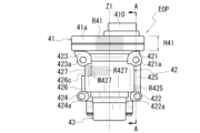
図2は、ハウジングHSを車両前方側から見た図である。この図2では、車両前方側から見た収容部68を、ハウジングHSの他の構成要素(ケース6、第1カバー7、第2カバー8)と共に模式的に示している。また、紙面手前側に位置する接合部683の領域に交差したハッチングを付して示している。また、コントロールバルブCVの外観を模式的に示している。
FIG. 2 is a diagram of the housing HS viewed from the front side of the vehicle. In FIG. 2, the accommodating portion 68 viewed from the front side of the vehicle is schematically shown together with other components of the housing HS (case 6, first cover 7, and second cover 8). Further, the region of the joint portion 683 located on the near side of the paper is shown with crossed hatching. Moreover, the external appearance of the control valve CV is schematically shown.
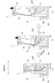
図3は、図2におけるA-A線に沿ってコントロールバルブCVと電動オイルポンプEOPを切断した断面を模式的に示した図である。
図3では、モータ部42の内部の図示を省略して断面を簡略的に示すと共に、コントロールバルブCVと第3カバー9を仮想線で示している。
図4は、図2におけるB-B線に沿ってコントロールバルブCVと電動オイルポンプEOPを切断した断面を模式的に示した図である。
図4では、モータ部42の内のモータMの位置を破線で略的に示すと共に、コントロールバルブCVと治具5を仮想線で示している。 FIG. 3 is a diagram schematically showing a cross section of the control valve CV and the electric oil pump EOP taken along the line AA in FIG.
In FIG. 3, illustration of the inside of themotor section 42 is omitted and a cross section is simply shown, and the control valve CV and the third cover 9 are shown with imaginary lines.
FIG. 4 is a diagram schematically showing a cross section of the control valve CV and electric oil pump EOP taken along line BB in FIG.
In FIG. 4, the position of the motor M in themotor section 42 is schematically shown with a broken line, and the control valve CV and the jig 5 are shown with imaginary lines.
図3では、モータ部42の内部の図示を省略して断面を簡略的に示すと共に、コントロールバルブCVと第3カバー9を仮想線で示している。
図4は、図2におけるB-B線に沿ってコントロールバルブCVと電動オイルポンプEOPを切断した断面を模式的に示した図である。
図4では、モータ部42の内のモータMの位置を破線で略的に示すと共に、コントロールバルブCVと治具5を仮想線で示している。 FIG. 3 is a diagram schematically showing a cross section of the control valve CV and the electric oil pump EOP taken along the line AA in FIG.
In FIG. 3, illustration of the inside of the
FIG. 4 is a diagram schematically showing a cross section of the control valve CV and electric oil pump EOP taken along line BB in FIG.
In FIG. 4, the position of the motor M in the
図2に示すように、ケース6では、車両前方側の側面に、収容部68が付設されている。
収容部68は、開口を車両前方側に向けて設けられている。収容部68の紙面奥側の壁部682は、ハウジングHS内の動力伝達機構の回転軸Xに沿う向きで設けられている。回転軸Xの径方向から見て収容部68は、ケース6の周壁部61の領域から、第1カバー7の側方まで及ぶ回転軸X方向(図中、左右方向)の範囲を持って形成されている。 As shown in FIG. 2, in thecase 6, a housing portion 68 is attached to the side surface on the front side of the vehicle.
Thehousing portion 68 is provided with an opening facing toward the front side of the vehicle. A wall portion 682 of the accommodating portion 68 on the back side in the drawing is oriented along the rotation axis X of the power transmission mechanism within the housing HS. Viewed from the radial direction of the rotation axis has been done.
収容部68は、開口を車両前方側に向けて設けられている。収容部68の紙面奥側の壁部682は、ハウジングHS内の動力伝達機構の回転軸Xに沿う向きで設けられている。回転軸Xの径方向から見て収容部68は、ケース6の周壁部61の領域から、第1カバー7の側方まで及ぶ回転軸X方向(図中、左右方向)の範囲を持って形成されている。 As shown in FIG. 2, in the
The
収容部68の壁部682は、第2カバー8側の略半分の領域が、ケース6側の周壁部61と一体になっている。第2カバー8とは反対側の略半分の領域は、周壁部61の延長上で、第1カバー7の外周との間に隙間を開けて設けられている。
Approximately half of the wall portion 682 of the accommodating portion 68 on the second cover 8 side is integrated with the peripheral wall portion 61 on the case 6 side. Approximately half the region on the opposite side of the second cover 8 is provided on an extension of the peripheral wall portion 61 with a gap between it and the outer periphery of the first cover 7 .
図2に示すように、車両前方側から見て収容部68は、壁部682と、壁部682の外周を全周に亘って囲む周壁部681を有している。周壁部681の紙面手前側の端面は、第3カバー9との接合部683となっている。
図1および図3に示すように、接合部683には、第3カバー9側の接合部911が全周に亘って接合される。収容部68と第3カバー9は、互いの接合部683、911同士を接合した状態で、図示しないボルトで連結される。 As shown in FIG. 2, theaccommodating portion 68 includes a wall portion 682 and a peripheral wall portion 681 that surrounds the entire outer periphery of the wall portion 682 when viewed from the front side of the vehicle. The end surface of the peripheral wall portion 681 on the near side in the drawing forms a joint portion 683 with the third cover 9.
As shown in FIGS. 1 and 3, ajoint portion 911 on the third cover 9 side is joined to the joint portion 683 over the entire circumference. The accommodating portion 68 and the third cover 9 are connected with bolts (not shown) with their joint portions 683 and 911 joined together.
図1および図3に示すように、接合部683には、第3カバー9側の接合部911が全周に亘って接合される。収容部68と第3カバー9は、互いの接合部683、911同士を接合した状態で、図示しないボルトで連結される。 As shown in FIG. 2, the
As shown in FIGS. 1 and 3, a
周壁部681の内側は、コントロールバルブCVと電動オイルポンプEOPを収容する第2室S2となっている。
図3に示すようにコントロールバルブCVは、バルブボディ921、921の間にセパレートプレート920を挟み込んだ基本構成を有している。コントロールバルブCVの内部には、油圧制御回路(図示せず)が形成されている。油圧制御回路には、制御装置(図示せず)からの指令に基づいて駆動するソレノイドや、ソレノイドで発生させた信号圧などで作動する調圧弁(スプール弁SP)が設けられている。 The inside of theperipheral wall portion 681 is a second chamber S2 that accommodates the control valve CV and the electric oil pump EOP.
As shown in FIG. 3, the control valve CV has a basic configuration in which aseparate plate 920 is sandwiched between valve bodies 921, 921. A hydraulic control circuit (not shown) is formed inside the control valve CV. The hydraulic control circuit is provided with a solenoid that is driven based on a command from a control device (not shown) and a pressure regulating valve (spool valve SP) that is operated by signal pressure generated by the solenoid.
図3に示すようにコントロールバルブCVは、バルブボディ921、921の間にセパレートプレート920を挟み込んだ基本構成を有している。コントロールバルブCVの内部には、油圧制御回路(図示せず)が形成されている。油圧制御回路には、制御装置(図示せず)からの指令に基づいて駆動するソレノイドや、ソレノイドで発生させた信号圧などで作動する調圧弁(スプール弁SP)が設けられている。 The inside of the
As shown in FIG. 3, the control valve CV has a basic configuration in which a
図2に示すように、第2室S2内では、コントロールバルブCVが、バルブボディ921、921の積層方向を車両前後方向(紙面手前奥方向)に沿わせた向きで、縦置きされている。
第2室S2では、コントロールバルブCVが、以下の条件を満たすように、縦置きされている。(a)コントロールバルブCV内の複数のスプール弁SPが、動力伝達装置1の車両Vへの設置状態を基準とした鉛直線VL方向(上下方向)に並ぶ、(b)スプール弁SPの進退移動方向Xpが水平線方向(図2における左右方向)に沿う向きとなる。 As shown in FIG. 2, in the second chamber S2, the control valve CV is vertically placed with the stacking direction of the valve bodies 921, 921 aligned with the vehicle longitudinal direction (front to back direction in the paper).
In the second chamber S2, the control valve CV is vertically placed so as to satisfy the following conditions. (a) A plurality of spool valves SP in the control valve CV are lined up in the vertical line VL direction (vertical direction) based on the installation state of thepower transmission device 1 in the vehicle V, (b) forward and backward movement of the spool valve SP The direction Xp is along the horizontal direction (left-right direction in FIG. 2).
第2室S2では、コントロールバルブCVが、以下の条件を満たすように、縦置きされている。(a)コントロールバルブCV内の複数のスプール弁SPが、動力伝達装置1の車両Vへの設置状態を基準とした鉛直線VL方向(上下方向)に並ぶ、(b)スプール弁SPの進退移動方向Xpが水平線方向(図2における左右方向)に沿う向きとなる。 As shown in FIG. 2, in the second chamber S2, the control valve CV is vertically placed with the stacking direction of the
In the second chamber S2, the control valve CV is vertically placed so as to satisfy the following conditions. (a) A plurality of spool valves SP in the control valve CV are lined up in the vertical line VL direction (vertical direction) based on the installation state of the
これにより、スプール弁SPの進退移動が阻害されないようにしつつ、コントロールバルブCVが第2室S2内で縦置きされる。よって、第2室S2が車両前後方向に大型化しないようにされている。
As a result, the control valve CV is placed vertically within the second chamber S2 while preventing the forward and backward movement of the spool valve SP from being obstructed. Therefore, the second chamber S2 is prevented from increasing in size in the longitudinal direction of the vehicle.
図2に示すように、車両前方側から見てコントロールバルブCVは、略矩形形状のバルブボディ921に切欠部923を設けた略L字形状を成している。切欠部923は、電動オイルポンプEOPとの干渉を避けるために設けられている。
車両前方側から見て電動オイルポンプEOPは、第2カバー8側(図中、左側)の一部が切欠部923に収容されている。
そのため、鉛直線VL方向から見ると、電動オイルポンプEOPの一部が、コントロールバルブCVと重なる位置関係で設けられている。 As shown in FIG. 2, when viewed from the front side of the vehicle, the control valve CV has a substantially L-shape in which anotch 923 is provided in a substantially rectangular valve body 921. The notch 923 is provided to avoid interference with the electric oil pump EOP.
When viewed from the front side of the vehicle, a portion of thesecond cover 8 side (left side in the figure) of the electric oil pump EOP is accommodated in the notch 923.
Therefore, when viewed from the direction of the vertical line VL, a part of the electric oil pump EOP is provided in a positional relationship overlapping with the control valve CV.
車両前方側から見て電動オイルポンプEOPは、第2カバー8側(図中、左側)の一部が切欠部923に収容されている。
そのため、鉛直線VL方向から見ると、電動オイルポンプEOPの一部が、コントロールバルブCVと重なる位置関係で設けられている。 As shown in FIG. 2, when viewed from the front side of the vehicle, the control valve CV has a substantially L-shape in which a
When viewed from the front side of the vehicle, a portion of the
Therefore, when viewed from the direction of the vertical line VL, a part of the electric oil pump EOP is provided in a positional relationship overlapping with the control valve CV.
図2に示すように、第2室S2内では、コントロールバルブCVと電動オイルポンプEOPとが、動力伝達機構の回転軸X方向(図2における左右方向)に並んでいる。
車両前方側から見てコントロールバルブCVは、ケース6と重なる位置関係で設けられている。車両前方側から見て電動オイルポンプEOPは、第1カバー7と重なる位置関係で設けられている。 As shown in FIG. 2, in the second chamber S2, the control valve CV and the electric oil pump EOP are lined up in the direction of the rotation axis X of the power transmission mechanism (the left-right direction in FIG. 2).
The control valve CV is provided so as to overlap thecase 6 when viewed from the front side of the vehicle. The electric oil pump EOP is provided so as to overlap the first cover 7 when viewed from the front side of the vehicle.
車両前方側から見てコントロールバルブCVは、ケース6と重なる位置関係で設けられている。車両前方側から見て電動オイルポンプEOPは、第1カバー7と重なる位置関係で設けられている。 As shown in FIG. 2, in the second chamber S2, the control valve CV and the electric oil pump EOP are lined up in the direction of the rotation axis X of the power transmission mechanism (the left-right direction in FIG. 2).
The control valve CV is provided so as to overlap the
図2に示すように電動オイルポンプEOPは、制御部41と、モータ部42と、ポンプ部43が、モータMの回転軸Z1方向で直列に並んだ基本構成を有する。
車両前方側から見て、電動オイルポンプEOPは、回転軸Z1を、動力伝達機構の回転軸Xに直交させた向きで設けられている。この状態において、電動オイルポンプEOPは、ポンプ部43を第2室S2内の下部側に、制御部41を第2室S2内の上部側に、それぞれ位置させる向きで縦置きされている。 As shown in FIG. 2, the electric oil pump EOP has a basic configuration in which acontrol section 41, a motor section 42, and a pump section 43 are arranged in series in the direction of the rotation axis Z1 of the motor M.
When viewed from the front side of the vehicle, the electric oil pump EOP is provided with the rotation axis Z1 orthogonal to the rotation axis X of the power transmission mechanism. In this state, the electric oil pump EOP is vertically placed with thepump section 43 located at the lower side of the second chamber S2 and the control section 41 located at the upper side of the second chamber S2.
車両前方側から見て、電動オイルポンプEOPは、回転軸Z1を、動力伝達機構の回転軸Xに直交させた向きで設けられている。この状態において、電動オイルポンプEOPは、ポンプ部43を第2室S2内の下部側に、制御部41を第2室S2内の上部側に、それぞれ位置させる向きで縦置きされている。 As shown in FIG. 2, the electric oil pump EOP has a basic configuration in which a
When viewed from the front side of the vehicle, the electric oil pump EOP is provided with the rotation axis Z1 orthogonal to the rotation axis X of the power transmission mechanism. In this state, the electric oil pump EOP is vertically placed with the
図2に示すように、収容部68の壁部682では、車両前方側から見たときに第1カバー7と重なる領域に凹部69が設けられている。凹部69は、電動オイルポンプEOPを収容可能な鉛直線VL方向の高さH69の範囲に形成されている。
図3に示すように、凹部69は、壁部682を第1カバー7側(図中、下側)に窪ませて形成される。凹部69の車幅方向の幅W69は、電動オイルポンプEOPの制御部41の幅W41よりも僅かに大きくなっている(W69>W41)。 As shown in FIG. 2, arecess 69 is provided in the wall portion 682 of the accommodating portion 68 in a region that overlaps with the first cover 7 when viewed from the front side of the vehicle. The recess 69 is formed within a height H69 range in the vertical line VL direction that can accommodate the electric oil pump EOP.
As shown in FIG. 3, therecess 69 is formed by recessing the wall 682 toward the first cover 7 (lower side in the figure). The width W69 of the recessed portion 69 in the vehicle width direction is slightly larger than the width W41 of the control portion 41 of the electric oil pump EOP (W69>W41).
図3に示すように、凹部69は、壁部682を第1カバー7側(図中、下側)に窪ませて形成される。凹部69の車幅方向の幅W69は、電動オイルポンプEOPの制御部41の幅W41よりも僅かに大きくなっている(W69>W41)。 As shown in FIG. 2, a
As shown in FIG. 3, the
凹部69の車両前後方向の深さD69は、後記するフランジ部425が、収容部68の接合部683よりも車両前方側に位置すると共に、モータの回転軸Z1が、壁部682よりも車両前方側に位置するように設定されている。
The depth D69 of the recessed portion 69 in the vehicle longitudinal direction is such that the flange portion 425 (described later) is located further forward of the vehicle than the joint portion 683 of the housing portion 68, and the rotation axis Z1 of the motor is located further forward of the vehicle than the wall portion 682. It is set to be located on the side.
本実施形態では、電動オイルポンプEOPの一部を凹部69内に収容することで、電動オイルポンプEOP(制御部41)の車両前方側の側縁41aと、コントロールバルブCV(バルブボディ921)の車両前方側の側縁921aとが、略面一となる位置に配置されるようにしている。これにより、第2室S2が車両前方側に大型化しないようにしている。
In this embodiment, by housing a part of the electric oil pump EOP in the recess 69, the side edge 41a of the electric oil pump EOP (control unit 41) on the vehicle front side and the control valve CV (valve body 921) It is arranged so that the side edge 921a on the vehicle front side is substantially flush with the side edge 921a. This prevents the second chamber S2 from increasing in size toward the front of the vehicle.
図5は、電動オイルポンプEOPの正面図である。図5は、第2室S2に配置された電動オイルポンプEOPを車両前方側から見た状態を模式的に示している。
図6は、電動オイルポンプEOPの一部を断面で示した側面図である。なお、図6は、図5におけるA-A線に沿って電動オイルポンプEOPを切断した断面を模式的に示している。
なお、以下の説明においては、電動オイルポンプEOPの各構成要素の位置関係を、必要に応じて、動力伝達装置1の車両Vへの設置状態を基準とした方向を用いて説明する。 FIG. 5 is a front view of the electric oil pump EOP. FIG. 5 schematically shows the electric oil pump EOP disposed in the second chamber S2 as viewed from the front side of the vehicle.
FIG. 6 is a side view showing a part of the electric oil pump EOP in cross section. Note that FIG. 6 schematically shows a cross section of the electric oil pump EOP taken along line AA in FIG.
In the following description, the positional relationship of each component of the electric oil pump EOP will be explained using directions based on the installation state of thepower transmission device 1 in the vehicle V, as necessary.
図6は、電動オイルポンプEOPの一部を断面で示した側面図である。なお、図6は、図5におけるA-A線に沿って電動オイルポンプEOPを切断した断面を模式的に示している。
なお、以下の説明においては、電動オイルポンプEOPの各構成要素の位置関係を、必要に応じて、動力伝達装置1の車両Vへの設置状態を基準とした方向を用いて説明する。 FIG. 5 is a front view of the electric oil pump EOP. FIG. 5 schematically shows the electric oil pump EOP disposed in the second chamber S2 as viewed from the front side of the vehicle.
FIG. 6 is a side view showing a part of the electric oil pump EOP in cross section. Note that FIG. 6 schematically shows a cross section of the electric oil pump EOP taken along line AA in FIG.
In the following description, the positional relationship of each component of the electric oil pump EOP will be explained using directions based on the installation state of the
図3に示すように、電動オイルポンプEOPの制御部41は、回転軸Z1方向から見て略矩形形状を成している。図5に示すように、回転軸Z1の径方向から見て制御部41は、回転軸Z1方向に厚みH41を有している。制御部41の紙面手前側の側縁41aは、後記する治具5の当接部53が当接する平坦面となっている(図6参照)。
図6に示すように、制御部41の側縁41aは、後記するフランジ部425の係止面425bに対して、略平行な平坦面である。図6では、側縁41aと、係止面425bは、回転軸Z1に対して平行である。
なお、図5において交差したハッチングを付した領域R41が、当接部53が当接する領域である。この領域は、後記するモータMの回転軸Z1を、回転軸Z1の直交方向(図5における左右方向)に横切る範囲に設定されている。 As shown in FIG. 3, thecontrol unit 41 of the electric oil pump EOP has a substantially rectangular shape when viewed from the direction of the rotation axis Z1. As shown in FIG. 5, the control section 41 has a thickness H41 in the direction of the rotation axis Z1 when viewed from the radial direction of the rotation axis Z1. A side edge 41a of the control section 41 on the near side in the drawing is a flat surface that is in contact with a contact section 53 of a jig 5, which will be described later (see FIG. 6).
As shown in FIG. 6, theside edge 41a of the control section 41 is a flat surface that is substantially parallel to a locking surface 425b of a flange section 425, which will be described later. In FIG. 6, the side edge 41a and the locking surface 425b are parallel to the rotation axis Z1.
Note that a region R41 with cross hatching in FIG. 5 is a region in which the abuttingportion 53 abuts. This area is set in a range that crosses a rotation axis Z1 of a motor M, which will be described later, in a direction perpendicular to the rotation axis Z1 (left-right direction in FIG. 5).
図6に示すように、制御部41の側縁41aは、後記するフランジ部425の係止面425bに対して、略平行な平坦面である。図6では、側縁41aと、係止面425bは、回転軸Z1に対して平行である。
なお、図5において交差したハッチングを付した領域R41が、当接部53が当接する領域である。この領域は、後記するモータMの回転軸Z1を、回転軸Z1の直交方向(図5における左右方向)に横切る範囲に設定されている。 As shown in FIG. 3, the
As shown in FIG. 6, the
Note that a region R41 with cross hatching in FIG. 5 is a region in which the abutting
制御部41の内部には、モータの駆動用の制御基板(図示せず)が収容されている。制御部41では、モータ部42とは反対側(図中、上側)の面に、電力供給線との接続部410が付設されている。
A control board (not shown) for driving the motor is housed inside the control unit 41. In the control section 41, a connection section 410 for connecting to a power supply line is attached to the surface opposite to the motor section 42 (upper side in the figure).
モータ部42の内部には、ロータコアMRと、ロータコアMRの外周を囲むステータコアMSが収容される。そのため、モータ部42は、回転軸Z1に直交する断面の基本形状が円形を成している(図3参照)。
A rotor core MR and a stator core MS surrounding the outer periphery of the rotor core MR are housed inside the motor section 42. Therefore, the basic shape of the motor section 42 in a cross section perpendicular to the rotation axis Z1 is circular (see FIG. 3).
ここで、本明細書における用語「基本形状」とは、モータ部42が持つ基本的な形状や、モータ部42としての機能を確保するために必要な基本的な形状を意味する。
例えば、図4に示すように、モータMのロータコアMRは、回転軸Z1に直交する断面の外形が円形である。モータMのステータコアMSは、ロータコアMRの外周を全周に亘って囲むことができる形状を持つ。よって、モータMのステータコアMSもまた、回転軸Z1に直交する断面の外径が円形である。そうすると、モータMを内部に収容するために、モータ部42が持つ必要な断面形状は円形となる。 Here, the term "basic shape" in this specification means the basic shape of themotor section 42 or the basic shape necessary to ensure the function of the motor section 42.
For example, as shown in FIG. 4, the rotor core MR of the motor M has a circular outer shape in a cross section perpendicular to the rotation axis Z1. Stator core MS of motor M has a shape that can surround the entire outer periphery of rotor core MR. Therefore, the stator core MS of the motor M also has a circular outer diameter in a cross section perpendicular to the rotation axis Z1. Then, in order to accommodate the motor M therein, the necessary cross-sectional shape of themotor section 42 becomes circular.
例えば、図4に示すように、モータMのロータコアMRは、回転軸Z1に直交する断面の外形が円形である。モータMのステータコアMSは、ロータコアMRの外周を全周に亘って囲むことができる形状を持つ。よって、モータMのステータコアMSもまた、回転軸Z1に直交する断面の外径が円形である。そうすると、モータMを内部に収容するために、モータ部42が持つ必要な断面形状は円形となる。 Here, the term "basic shape" in this specification means the basic shape of the
For example, as shown in FIG. 4, the rotor core MR of the motor M has a circular outer shape in a cross section perpendicular to the rotation axis Z1. Stator core MS of motor M has a shape that can surround the entire outer periphery of rotor core MR. Therefore, the stator core MS of the motor M also has a circular outer diameter in a cross section perpendicular to the rotation axis Z1. Then, in order to accommodate the motor M therein, the necessary cross-sectional shape of the
図4の場合には、後記するフランジ部425が存在するため、図4に示すモータ部42の断面形状は円形ではない。しかし、フランジ部425は、モータMを内部に収容するために、モータ部42が持つ必要な断面形状とは関係が無い。よって、図4では、モータ部42の断面の基本形状は、円形であるといえる。
In the case of FIG. 4, since a flange portion 425, which will be described later, is present, the cross-sectional shape of the motor portion 42 shown in FIG. 4 is not circular. However, the flange portion 425 has no relation to the necessary cross-sectional shape of the motor portion 42 in order to accommodate the motor M therein. Therefore, in FIG. 4, it can be said that the basic cross-sectional shape of the motor section 42 is circular.
同様に、図3の場合には、後記するフランジ部425、426が存在するため、図3に示すモータ部42の断面形状は円形ではない。しかし、フランジ部425、426は、モータMを内部に収容するために、モータ部42が持つ必要な断面形状とは関係が無い。よって、図3では、モータ部42の断面の基本形状は、円形であるといえる。
Similarly, in the case of FIG. 3, since flange portions 425 and 426, which will be described later, are present, the cross-sectional shape of the motor portion 42 shown in FIG. 3 is not circular. However, the flange parts 425 and 426 have no relation to the necessary cross-sectional shape of the motor part 42 in order to accommodate the motor M therein. Therefore, in FIG. 3, it can be said that the basic cross-sectional shape of the motor section 42 is circular.
本実施形態では、後記する治具5の第2アーム52により、モータ部42の外周が支持される。そのため、「被支持部におけるモータの回転軸に直交する断面の形状」とは、モータ部42における第2アーム52により支持される領域の断面形状、少なくとも第2アーム52により支持される側の断面形状(図4における直線Lmよりも左側の領域の断面形状)を意味する。よって、「断面の基本形状が円形を成している」とは、図4の場合には、基本形状が円形、または円弧形状であることを意味する。
In this embodiment, the outer periphery of the motor section 42 is supported by the second arm 52 of the jig 5, which will be described later. Therefore, "the cross-sectional shape of the supported part perpendicular to the rotation axis of the motor" refers to the cross-sectional shape of the region of the motor part 42 supported by the second arm 52, at least the cross-sectional shape of the side supported by the second arm 52. It means the shape (the cross-sectional shape of the region on the left side of the straight line Lm in FIG. 4). Therefore, "the basic shape of the cross section is circular" means, in the case of FIG. 4, that the basic shape is circular or arcuate.
図5に示すように、車両前方側から見てモータ部42では、制御部41との境界部に、ボス部421、423が設けられている。さらに、ポンプ部43との境界部にもボス部422、424が設けられている。
As shown in FIG. 5, the motor section 42 is provided with boss sections 421 and 423 at the boundary with the control section 41 when viewed from the front side of the vehicle. Further, boss portions 422 and 424 are also provided at the boundary with the pump portion 43.
図6に示すようにボス部421、422は、電動オイルポンプEOPの組付け方向(図6では、車両前後方向)に直線状に延びている。ボス部421、422は、当該ボス部421、422の先端421b、422bが、収容部68の凹部69内で、底壁部691に当接する長さL42で形成されている。
ボス部421、422には、ボルトの挿通孔421a、422aが設けられている。 As shown in FIG. 6, the boss portions 421 and 422 extend linearly in the direction in which the electric oil pump EOP is assembled (in the longitudinal direction of the vehicle in FIG. 6). The boss portions 421 and 422 have a length L42 such that the tips 421b and 422b of the boss portions 421 and 422 abut against the bottom wall portion 691 within the recess 69 of the housing portion 68.
The boss portions 421 and 422 are provided with bolt insertion holes 421a and 422a.
ボス部421、422には、ボルトの挿通孔421a、422aが設けられている。 As shown in FIG. 6, the
The
図6において紙面奥側の隠れた位置にあるボス部423、424もまた、ボス部421、422と同様の構成を有している。これらボス部423、424にも、ボルトの挿通孔423a、424aが設けられている(図5参照)。
Boss parts 423 and 424 located in hidden positions on the back side of the paper in FIG. 6 also have the same configuration as boss parts 421 and 422. These boss portions 423 and 424 are also provided with bolt insertion holes 423a and 424a (see FIG. 5).
電動オイルポンプEOPは、挿通孔421a~424aを貫通したボルト(図示せず)により、収容部68の底壁部691に固定される。
回転軸Z1の径方向(図5における車両前方側)から見て、ボス部421、422と、ボス部423、424は、回転軸Z1を間に挟んで対称となる位置関係で設けられている。
電動オイルポンプEOPを第2室S2内に設置した状態では、ボス部423、424が、ボス部421、422よりもコントロールバルブCVに近い側に位置する。 The electric oil pump EOP is fixed to thebottom wall portion 691 of the housing portion 68 by bolts (not shown) passing through the insertion holes 421a to 424a.
When viewed from the radial direction of the rotation axis Z1 (vehicle front side in FIG. 5), the boss parts 421, 422 and the boss parts 423, 424 are provided in a symmetrical positional relationship with the rotation axis Z1 in between. .
When the electric oil pump EOP is installed in the second chamber S2, the boss portions 423 and 424 are located closer to the control valve CV than the boss portions 421 and 422 are.
回転軸Z1の径方向(図5における車両前方側)から見て、ボス部421、422と、ボス部423、424は、回転軸Z1を間に挟んで対称となる位置関係で設けられている。
電動オイルポンプEOPを第2室S2内に設置した状態では、ボス部423、424が、ボス部421、422よりもコントロールバルブCVに近い側に位置する。 The electric oil pump EOP is fixed to the
When viewed from the radial direction of the rotation axis Z1 (vehicle front side in FIG. 5), the
When the electric oil pump EOP is installed in the second chamber S2, the
図5および図6に示すように、回転軸Z1の一方側では、モータ部42の外周に、フランジ部425が設けられている。
フランジ部425は、ボス部421とボス部422の間に位置すると共に、ボス部421とボス部422とに跨がって設けられた板状の部位である。 As shown in FIGS. 5 and 6, aflange portion 425 is provided on the outer periphery of the motor portion 42 on one side of the rotation axis Z1.
Theflange portion 425 is a plate-shaped portion located between the boss portion 421 and the boss portion 422 and provided astride the boss portion 421 and the boss portion 422.
フランジ部425は、ボス部421とボス部422の間に位置すると共に、ボス部421とボス部422とに跨がって設けられた板状の部位である。 As shown in FIGS. 5 and 6, a
The
図3に示すように、フランジ部425は、直線Ln1に沿って、直線Lmから離れる方向(コントロールバルブCVから離れる方向)に延びている。ここで、直線Lmは、電動オイルポンプEOPの組付け方向に沿うと共に、モータMの回転軸Z1を通る直線である。直線Ln1は、直線Lmに直交すると共に、車幅方向に延びる直線である。直線Ln1は、制御部41の側縁41a、41bに対して平行な直線である。なお、直線Ln1は、直線Ln2に対して平行である。直線Ln2は、断面視におけるモータ部42の中心(回転軸Z1)を通ると共に、底壁部691に沿って、車幅方向に延びる直線である。
As shown in FIG. 3, the flange portion 425 extends along the straight line Ln1 in a direction away from the straight line Lm (in a direction away from the control valve CV). Here, the straight line Lm is a straight line that runs along the assembly direction of the electric oil pump EOP and passes through the rotation axis Z1 of the motor M. Straight line Ln1 is a straight line that is perpendicular to straight line Lm and extends in the vehicle width direction. The straight line Ln1 is a straight line parallel to the side edges 41a and 41b of the control section 41. Note that the straight line Ln1 is parallel to the straight line Ln2. The straight line Ln2 is a straight line that passes through the center (rotational axis Z1) of the motor section 42 in a cross-sectional view and extends in the vehicle width direction along the bottom wall section 691.
図3に示すように、回転軸Z1方向から見てフランジ部425の先端425aは、制御部41の側縁41cよりも僅かに内側(直線Lm側)に位置している。
電動オイルポンプEOPを凹部69に収容すると、フランジ部425は、周壁部681側の接合部683よりも第3カバー9側(図中、上側)に配置される。この状態においてフランジ部425は、接合部683から高さh分だけ離れて位置している。
フランジ部425の接合部683側の下面は、後記する治具5の爪部51a(図4参照)が係止される係止面425bとなっている。係止面425bは、制御部41の側縁41aに対して平行である。 As shown in FIG. 3, thetip 425a of the flange portion 425 is located slightly inside (on the straight line Lm side) of the side edge 41c of the control portion 41 when viewed from the direction of the rotation axis Z1.
When the electric oil pump EOP is accommodated in therecess 69, the flange portion 425 is located closer to the third cover 9 (upper side in the figure) than the joint 683 on the peripheral wall portion 681 side. In this state, the flange portion 425 is located apart from the joint portion 683 by a height h.
The lower surface of theflange portion 425 on the joint portion 683 side is a locking surface 425b on which a claw portion 51a (see FIG. 4) of the jig 5, which will be described later, is locked. The locking surface 425b is parallel to the side edge 41a of the control section 41.
電動オイルポンプEOPを凹部69に収容すると、フランジ部425は、周壁部681側の接合部683よりも第3カバー9側(図中、上側)に配置される。この状態においてフランジ部425は、接合部683から高さh分だけ離れて位置している。
フランジ部425の接合部683側の下面は、後記する治具5の爪部51a(図4参照)が係止される係止面425bとなっている。係止面425bは、制御部41の側縁41aに対して平行である。 As shown in FIG. 3, the
When the electric oil pump EOP is accommodated in the
The lower surface of the
モータ部42では、直線Lmから見てフランジ部425とは反対側(コントロールバルブCV側)にも、フランジ部426が設けられている。フランジ部426もまた、モータ部42の外周に設けられた板状の部位である。
フランジ部426は、直線Ln1に沿って、直線Lmから離れる方向に延びている。回転軸Z1方向から見てフランジ部426の先端426aは、制御部41の側縁41dよりも内側(直線Lm側)に位置している。 In themotor section 42, a flange section 426 is also provided on the opposite side of the flange section 425 (control valve CV side) when viewed from the straight line Lm. The flange portion 426 is also a plate-shaped portion provided on the outer periphery of the motor portion 42.
Theflange portion 426 extends along the straight line Ln1 in a direction away from the straight line Lm. The tip 426a of the flange portion 426 is located inside the side edge 41d of the control portion 41 (on the straight line Lm side) when viewed from the direction of the rotation axis Z1.
フランジ部426は、直線Ln1に沿って、直線Lmから離れる方向に延びている。回転軸Z1方向から見てフランジ部426の先端426aは、制御部41の側縁41dよりも内側(直線Lm側)に位置している。 In the
The
電動オイルポンプEOPを凹部69に収容すると、フランジ部426は、壁部682よりも第3カバー9側(図中、上側)に配置される。この状態においてフランジ部426は、壁部682から高さh'分だけ離れて位置している。
When the electric oil pump EOP is accommodated in the recess 69, the flange portion 426 is placed closer to the third cover 9 than the wall portion 682 (upper side in the figure). In this state, the flange portion 426 is located apart from the wall portion 682 by a height h'.
図5に示すように、フランジ部426は、ボス部424からボス部423側に向けて、回転軸Z1に沿って延びている。フランジ部426の先端426cは、ボス部423との間に隙間427を空けて対向している。この隙間427は、後記する治具5の第2アーム52が通過可能な幅W427で形成されている。そのため、フランジ部426とボス部423との間の隙間427は、後記する治具5の第2アーム52が通過可能な隙間である。
As shown in FIG. 5, the flange portion 426 extends from the boss portion 424 toward the boss portion 423 side along the rotation axis Z1. A tip 426c of the flange portion 426 faces the boss portion 423 with a gap 427 therebetween. This gap 427 is formed with a width W427 through which a second arm 52 of a jig 5, which will be described later, can pass through. Therefore, the gap 427 between the flange portion 426 and the boss portion 423 is a gap through which the second arm 52 of the jig 5, which will be described later, can pass.
電動オイルポンプEOPは、第2室S2内の凹部69に設置する際に、専用の治具5を用いて把持される。
図4に示すように、電動オイルポンプEOPでは、制御部41の側縁41aと、フランジ部425と、モータ部42の外周42aとが、治具5による把持に関与可能な部位となっている。 The electric oil pump EOP is held using adedicated jig 5 when installed in the recess 69 in the second chamber S2.
As shown in FIG. 4, in the electric oil pump EOP, theside edge 41a of the control part 41, the flange part 425, and the outer periphery 42a of the motor part 42 are parts that can be involved in gripping by the jig 5. .
図4に示すように、電動オイルポンプEOPでは、制御部41の側縁41aと、フランジ部425と、モータ部42の外周42aとが、治具5による把持に関与可能な部位となっている。 The electric oil pump EOP is held using a
As shown in FIG. 4, in the electric oil pump EOP, the
治具5は、フランジ部425に係止される爪部51aを持つ第1アーム51と、モータ部42の外周42aを支持する支持領域521を持つ第2アーム52と、制御部41の側縁41aに当接する当接部53と、を有している。
第2アーム52の先端52a側は、モータ部42の外周42aの支持領域521となっている。この支持領域521は、モータ部42の外周に沿う弧状を成している。 Thejig 5 includes a first arm 51 having a claw portion 51a that is locked to a flange portion 425, a second arm 52 having a support area 521 that supports the outer periphery 42a of the motor portion 42, and a side edge of the control portion 41. 41a, and a contact portion 53 that contacts 41a.
Thetip 52a side of the second arm 52 serves as a support area 521 for the outer periphery 42a of the motor section 42. This support region 521 has an arc shape along the outer periphery of the motor section 42 .
第2アーム52の先端52a側は、モータ部42の外周42aの支持領域521となっている。この支持領域521は、モータ部42の外周に沿う弧状を成している。 The
The
ここで、治具5により電動オイルポンプEOPを把持した状態を基準とすると、支持領域521は、直線Lpを、回転軸Z1周りの周方向に横切る範囲に設けられている。
ここで、直線Lpは、モータ部42における第1アーム51の爪部51aによる支持点と、回転軸Z1とを結ぶ直線であり、モータ部42の直径線に相当する。 Here, based on the state in which the electric oil pump EOP is gripped by thejig 5, the support region 521 is provided in a range that crosses the straight line Lp in the circumferential direction around the rotation axis Z1.
Here, the straight line Lp is a straight line connecting the support point of theclaw part 51a of the first arm 51 in the motor part 42 and the rotation axis Z1, and corresponds to the diameter line of the motor part 42.
ここで、直線Lpは、モータ部42における第1アーム51の爪部51aによる支持点と、回転軸Z1とを結ぶ直線であり、モータ部42の直径線に相当する。 Here, based on the state in which the electric oil pump EOP is gripped by the
Here, the straight line Lp is a straight line connecting the support point of the
第2アーム52の先端52aは、治具5により電動オイルポンプEOPを把持する際と、把持を解消する際に、モータ部42の外周42aを摺動する。
そのため、モータ部42の外周42aのうち、少なくとも第2アーム52の先端52aが摺動する領域の表面は、断面視において、回転軸Z1を中心とする円弧状に形成されている(図4における太線で示した領域)。 Thetip 52a of the second arm 52 slides on the outer periphery 42a of the motor section 42 when the electric oil pump EOP is gripped by the jig 5 and when the grip is released.
Therefore, the surface of the area on which at least thetip 52a of the second arm 52 slides on the outer periphery 42a of the motor section 42 is formed in an arc shape centered on the rotation axis Z1 in cross-sectional view (see FIG. 4). (area indicated by thick line).
そのため、モータ部42の外周42aのうち、少なくとも第2アーム52の先端52aが摺動する領域の表面は、断面視において、回転軸Z1を中心とする円弧状に形成されている(図4における太線で示した領域)。 The
Therefore, the surface of the area on which at least the
第1アーム51と第2アーム52は、共通の基部50で軸線Zb、Za回りに回動可能に支持されている。第1アーム51と第2アーム52は、図示しないアクチュエータにより、軸線Zb、Za回りに回動可能である。
軸線Zb、Za方向から見ると、第1アーム51と第2アーム52の間に、当接部53が位置している。
図6に示すように、治具5において、第1アーム51と、第2アーム52、当接部53は、モータの回転軸Z1方向に位置をずらして設けられている。 Thefirst arm 51 and the second arm 52 are supported by a common base 50 so as to be rotatable around axes Zb and Za. The first arm 51 and the second arm 52 are rotatable around axes Zb and Za by an actuator (not shown).
When viewed from the directions of the axes Zb and Za, thecontact portion 53 is located between the first arm 51 and the second arm 52.
As shown in FIG. 6, in thejig 5, the first arm 51, the second arm 52, and the contact portion 53 are provided with their positions shifted in the direction of the rotation axis Z1 of the motor.
軸線Zb、Za方向から見ると、第1アーム51と第2アーム52の間に、当接部53が位置している。
図6に示すように、治具5において、第1アーム51と、第2アーム52、当接部53は、モータの回転軸Z1方向に位置をずらして設けられている。 The
When viewed from the directions of the axes Zb and Za, the
As shown in FIG. 6, in the
以下、治具5を用いた電動オイルポンプEOPの凹部69内への設置を説明する。
図7は、治具5を用いた電動オイルポンプEOPの凹部69内への設置を説明する図である。
図8は、電動オイルポンプEOPを凹部69内に設置した後の第1アーム51の変位を説明する図である。
図9は、電動オイルポンプEOPを凹部69内に設置した後の第2アーム52の変位を説明する図である。 Hereinafter, installation of the electric oil pump EOP into therecess 69 using the jig 5 will be described.
FIG. 7 is a diagram illustrating installation of the electric oil pump EOP into therecess 69 using the jig 5. As shown in FIG.
FIG. 8 is a diagram illustrating the displacement of thefirst arm 51 after the electric oil pump EOP is installed in the recess 69.
FIG. 9 is a diagram illustrating the displacement of thesecond arm 52 after the electric oil pump EOP is installed in the recess 69.
図7は、治具5を用いた電動オイルポンプEOPの凹部69内への設置を説明する図である。
図8は、電動オイルポンプEOPを凹部69内に設置した後の第1アーム51の変位を説明する図である。
図9は、電動オイルポンプEOPを凹部69内に設置した後の第2アーム52の変位を説明する図である。 Hereinafter, installation of the electric oil pump EOP into the
FIG. 7 is a diagram illustrating installation of the electric oil pump EOP into the
FIG. 8 is a diagram illustrating the displacement of the
FIG. 9 is a diagram illustrating the displacement of the
始めに、電動オイルポンプEOPを治具5で把持すると、図4に示すように、第1アーム51の爪部51aは、電動オイルポンプEOPのフランジ部425に係止される。
爪部51aは、第1アーム51の下端から第2アーム52側に突出している。爪部51aの上面52bは、フランジ部425の係止面425b(図3参照)に接触可能な平坦面である。
第1アーム51の爪部51aは、フランジ部425の係止面425bに、面接触した状態で係止される。図5に示すように、フランジ部425において交差したハッチングを付した領域R425の紙面裏側の係止面425bが、第1アーム51の爪部51aで支持される。
第2アーム52の支持領域521は、モータ部42の外周42aを支持する(図4参照)。当接部53が、制御部41の側縁41aに当接する(図4参照)。
この状態においてモータ部42の外周42aのうち、図5において交差したハッチングを付した領域R427の紙面奥側に位置する外周42aが、第2アーム52の支持領域521で支持される。当接部53は、制御部41の領域R41(図5において交差したハッチングを付した領域)に当接する。 First, when the electric oil pump EOP is gripped by thejig 5, the claw portion 51a of the first arm 51 is locked to the flange portion 425 of the electric oil pump EOP, as shown in FIG.
Theclaw portion 51a projects from the lower end of the first arm 51 toward the second arm 52 side. The upper surface 52b of the claw portion 51a is a flat surface that can come into contact with the locking surface 425b (see FIG. 3) of the flange portion 425.
Theclaw portion 51a of the first arm 51 is locked in surface contact with the locking surface 425b of the flange portion 425. As shown in FIG. 5, a locking surface 425b on the back side of the paper in a cross-hatched region R425 of the flange portion 425 is supported by the claw portion 51a of the first arm 51. As shown in FIG.
Thesupport area 521 of the second arm 52 supports the outer periphery 42a of the motor section 42 (see FIG. 4). The contact portion 53 contacts the side edge 41a of the control portion 41 (see FIG. 4).
In this state, of theouter periphery 42a of the motor section 42, the outer periphery 42a located on the back side of the plane of the paper of the cross-hatched area R427 in FIG. 5 is supported by the support area 521 of the second arm 52. The contact portion 53 contacts a region R41 of the control portion 41 (the region indicated by cross hatching in FIG. 5).
爪部51aは、第1アーム51の下端から第2アーム52側に突出している。爪部51aの上面52bは、フランジ部425の係止面425b(図3参照)に接触可能な平坦面である。
第1アーム51の爪部51aは、フランジ部425の係止面425bに、面接触した状態で係止される。図5に示すように、フランジ部425において交差したハッチングを付した領域R425の紙面裏側の係止面425bが、第1アーム51の爪部51aで支持される。
第2アーム52の支持領域521は、モータ部42の外周42aを支持する(図4参照)。当接部53が、制御部41の側縁41aに当接する(図4参照)。
この状態においてモータ部42の外周42aのうち、図5において交差したハッチングを付した領域R427の紙面奥側に位置する外周42aが、第2アーム52の支持領域521で支持される。当接部53は、制御部41の領域R41(図5において交差したハッチングを付した領域)に当接する。 First, when the electric oil pump EOP is gripped by the
The
The
The
In this state, of the
この状態で、治具5を持ち挙げると、電動オイルポンプEOPには、第1アーム51の爪部51aによる係止点から、電動オイルポンプEOPを回転させる方向(図4における反時計CCW回り方向)のモーメントが作用する。
このモーメントは、図5に示す電動オイルポンプEOPを回転軸Z1回りに回転させる方向に作用する。ここで、治具5の当接部53が、制御部41の側縁41aの領域R41に当接している。この領域R41は、回転軸Z1の一方側に位置するフランジ部425側から、他方側に位置するフランジ部426側に向けて、回転軸Z1を横切る範囲である。図5では、フランジ部425に爪部51aからの操作力が作用する。しかし、治具5の当接部53が、回転軸Z1よりもフランジ部425側まで及ぶ領域R41に当接している。そのため、モータ部42の回転軸Z1回りの回転が、制御部41に当接する当接部53により規制される。そのため、電動オイルポンプEOPの回転が、当接部53により規制される。 When thejig 5 is lifted in this state, the electric oil pump EOP is rotated from the locking point by the claw portion 51a of the first arm 51 in the direction in which the electric oil pump EOP is rotated (counterclockwise CCW direction in FIG. 4). ) moment acts.
This moment acts in a direction to rotate the electric oil pump EOP shown in FIG. 5 around the rotation axis Z1. Here, thecontact portion 53 of the jig 5 is in contact with the region R41 of the side edge 41a of the control portion 41. This region R41 is a range that crosses the rotation axis Z1 from the flange portion 425 side located on one side of the rotation axis Z1 toward the flange portion 426 side located on the other side. In FIG. 5, the operating force from the claw portion 51a acts on the flange portion 425. However, the contact portion 53 of the jig 5 is in contact with a region R41 that extends closer to the flange portion 425 than the rotation axis Z1. Therefore, rotation of the motor section 42 around the rotation axis Z1 is regulated by the contact section 53 that comes into contact with the control section 41. Therefore, the rotation of the electric oil pump EOP is regulated by the contact portion 53.
このモーメントは、図5に示す電動オイルポンプEOPを回転軸Z1回りに回転させる方向に作用する。ここで、治具5の当接部53が、制御部41の側縁41aの領域R41に当接している。この領域R41は、回転軸Z1の一方側に位置するフランジ部425側から、他方側に位置するフランジ部426側に向けて、回転軸Z1を横切る範囲である。図5では、フランジ部425に爪部51aからの操作力が作用する。しかし、治具5の当接部53が、回転軸Z1よりもフランジ部425側まで及ぶ領域R41に当接している。そのため、モータ部42の回転軸Z1回りの回転が、制御部41に当接する当接部53により規制される。そのため、電動オイルポンプEOPの回転が、当接部53により規制される。 When the
This moment acts in a direction to rotate the electric oil pump EOP shown in FIG. 5 around the rotation axis Z1. Here, the
この状態おいて、治具5をさらに持ち上げると、電動オイルポンプEOPには、第1アーム51から離れる方向(図4における左方向)に荷重が作用する。
ここで、第2アーム52の支持領域521が、第1アーム51の爪部51aによる係止点とは反対側で、モータ部42の外周42aを支持している。そのため、電動オイルポンプEOPの第1アーム51から離れる方向への移動が、支持領域521により規制される。 In this state, when thejig 5 is further lifted, a load acts on the electric oil pump EOP in a direction away from the first arm 51 (leftward in FIG. 4).
Here, thesupport region 521 of the second arm 52 supports the outer periphery 42a of the motor section 42 on the opposite side from the locking point by the claw section 51a of the first arm 51. Therefore, movement of the electric oil pump EOP in the direction away from the first arm 51 is restricted by the support area 521.
ここで、第2アーム52の支持領域521が、第1アーム51の爪部51aによる係止点とは反対側で、モータ部42の外周42aを支持している。そのため、電動オイルポンプEOPの第1アーム51から離れる方向への移動が、支持領域521により規制される。 In this state, when the
Here, the
さらに、図5に示すように第2アーム52は、フランジ部426とボス部423との間の隙間427内に位置している。そのため、治具5と電動オイルポンプEOPとの回転軸Z1方向での相対移動も規制される。
よって、治具5に把持された電動オイルポンプEOPは、大きくガタつくこと無く、第2アーム52との相対移動が規制される。 Further, as shown in FIG. 5, thesecond arm 52 is located within a gap 427 between the flange portion 426 and the boss portion 423. Therefore, relative movement between the jig 5 and the electric oil pump EOP in the direction of the rotation axis Z1 is also restricted.
Therefore, the electric oil pump EOP held by thejig 5 does not wobble significantly, and its relative movement with the second arm 52 is restricted.
よって、治具5に把持された電動オイルポンプEOPは、大きくガタつくこと無く、第2アーム52との相対移動が規制される。 Further, as shown in FIG. 5, the
Therefore, the electric oil pump EOP held by the
治具5で把持された電動オイルポンプEOPを、収容部68内(第2室S2内)に設置する際には、図7に示すように、ケース6は、収容部68の開口を上方に向けた状態で保持される。この状態でコントロールバルブCVを設置した後、治具5で把持された電動オイルポンプEOPを上方から下方に向けて移動させて凹部69内に設置する。
When installing the electric oil pump EOP gripped by the jig 5 into the housing section 68 (inside the second chamber S2), the case 6 should be placed with the opening of the housing section 68 facing upward, as shown in FIG. It is held facing the target. After installing the control valve CV in this state, the electric oil pump EOP held by the jig 5 is moved downward from above and installed in the recess 69.
凹部69内への電動オイルポンプEOPの設置が完了すると、第1アーム51の爪部51aは、収容部68(接合部683)と、フランジ部425との間に配置される(図8の(a)参照)。具体的には、収容部68とフランジ部425との間に高さh分の隙間が存在するため、この高さh分の隙間に爪部51aが位置することになる。
この状態で、図示しないアクチュエータにより第1アーム51を変位させて爪部51aをフランジ部425から離間させる。そうすると、爪部51aの外側に接合部683が位置していないので、爪部51aは、接合部683と干渉することなく、フランジ部425から離間する。これにより、爪部51aによるフランジ部425の支持を解消できる(図8の(b)参照)。 When the installation of the electric oil pump EOP in therecess 69 is completed, the claw portion 51a of the first arm 51 is disposed between the housing portion 68 (joint portion 683) and the flange portion 425 (as shown in FIG. 8). a)). Specifically, since there is a gap of height h between the accommodating part 68 and the flange part 425, the claw part 51a is located in this gap of height h.
In this state, thefirst arm 51 is displaced by an actuator (not shown) to separate the claw portion 51a from the flange portion 425. Then, since the joint portion 683 is not located outside the claw portion 51a, the claw portion 51a is separated from the flange portion 425 without interfering with the joint portion 683. This makes it possible to eliminate the support of the flange portion 425 by the claw portion 51a (see (b) in FIG. 8).
この状態で、図示しないアクチュエータにより第1アーム51を変位させて爪部51aをフランジ部425から離間させる。そうすると、爪部51aの外側に接合部683が位置していないので、爪部51aは、接合部683と干渉することなく、フランジ部425から離間する。これにより、爪部51aによるフランジ部425の支持を解消できる(図8の(b)参照)。 When the installation of the electric oil pump EOP in the
In this state, the
そして、治具5を電動オイルポンプEOPから離れる方向(図中、上方向)に移動させると、当接部53が、制御部41の側縁41aから離れることになる。
Then, when the jig 5 is moved in the direction away from the electric oil pump EOP (upward in the figure), the contact portion 53 separates from the side edge 41a of the control portion 41.
治具5を電動オイルポンプEOPから離れる方向(図中、上方向)に移動させると、第2アーム52の先端52aが、モータ部42の外周42aを摺動しながら、上方に向けて変位する(図9の(a)、(b)参照)。
これに伴い、第2アーム52は、回転軸Z1から離れる方向(コントロールバルブCVに近づく方向)に変位することになる。
先端52aが直線Ln2と交差する位置に達した時点が、第2アーム52がコントロールバルブCVに最も近づくことになる。
本実施形態では、先端52aが直線Ln2と交差する位置に達した時点で、第2アーム52が制御部41の側縁41dよりも外側に到達しないように、モータ部42と制御部41との位置関係が設定されている。 When thejig 5 is moved in the direction away from the electric oil pump EOP (upward in the figure), the tip 52a of the second arm 52 is displaced upward while sliding on the outer periphery 42a of the motor section 42. (See (a) and (b) in FIG. 9).
Accordingly, thesecond arm 52 is displaced in the direction away from the rotation axis Z1 (in the direction toward the control valve CV).
Thesecond arm 52 comes closest to the control valve CV when the tip 52a reaches the position where it intersects the straight line Ln2.
In this embodiment, themotor section 42 and the control section 41 are connected so that the second arm 52 does not reach outside the side edge 41d of the control section 41 when the tip 52a reaches the position where it intersects the straight line Ln2. The positional relationship is set.
これに伴い、第2アーム52は、回転軸Z1から離れる方向(コントロールバルブCVに近づく方向)に変位することになる。
先端52aが直線Ln2と交差する位置に達した時点が、第2アーム52がコントロールバルブCVに最も近づくことになる。
本実施形態では、先端52aが直線Ln2と交差する位置に達した時点で、第2アーム52が制御部41の側縁41dよりも外側に到達しないように、モータ部42と制御部41との位置関係が設定されている。 When the
Accordingly, the
The
In this embodiment, the
ここで、制御部41の側縁41dは、凹部69のコントロールバルブCV側の側縁69aに近接して配置されている。そのため、制御部41の側縁41dは、側縁69a側に位置するコントロールバルブCVにも近接して配置されている。
上記のとおり、第2アーム52の先端52aが直線Ln2と交差する位置に達した時点で、第2アーム52が制御部41の側縁41dよりも外側に到達しないので、第2アーム52は、凹部69を超えて壁部682の領域まで到達しない。 Here, theside edge 41d of the control portion 41 is arranged close to the side edge 69a of the recess 69 on the control valve CV side. Therefore, the side edge 41d of the control section 41 is also arranged close to the control valve CV located on the side edge 69a side.
As described above, when thetip 52a of the second arm 52 reaches the position where it intersects the straight line Ln2, the second arm 52 does not reach outside the side edge 41d of the control section 41, so the second arm 52 It does not reach beyond the recess 69 to the area of the wall 682.
上記のとおり、第2アーム52の先端52aが直線Ln2と交差する位置に達した時点で、第2アーム52が制御部41の側縁41dよりも外側に到達しないので、第2アーム52は、凹部69を超えて壁部682の領域まで到達しない。 Here, the
As described above, when the
これにより、治具5による電動オイルポンプEOPの把持を解消して、治具5を電動オイルポンプEOPから離す方向(図中、上方向)に移動させる際に、コントロールバルブCV側に変位する第2アーム52が、壁部682に設置されたコントロールバルブCVに干渉しないようになっている。
As a result, when the grip of the electric oil pump EOP by the jig 5 is released and the jig 5 is moved in the direction away from the electric oil pump EOP (in the upward direction in the figure), the first position is displaced toward the control valve CV side. The two arms 52 are designed not to interfere with the control valve CV installed on the wall portion 682.
このように、コントロールバルブCV側に位置する第2アーム52は、回転軸Z1方向から見て電動オイルポンプEOP(制御部41)よりも外方まで変位しないので(図9の(b)参照)、電動オイルポンプEOPとコントロールバルブCVを近づけて配置できる。
In this way, the second arm 52 located on the control valve CV side is not displaced further outward than the electric oil pump EOP (control unit 41) when viewed from the rotation axis Z1 direction (see (b) in FIG. 9). , electric oil pump EOP and control valve CV can be placed close together.
さらに、コントロールバルブCVとは反対側位置する第1アーム51は、図8に示すように、回転軸Z1方向から見て電動オイルポンプEOP(制御部41)側のフランジ部425と、収容部68の接合部683との間の隙間に、爪部51aを位置させているので、爪部51aをフランジ部425から離れる方向(図中、右方向)に変位させても、爪部51aが収容部68側の周壁部681(接合部683)に干渉しない。これにより、電動オイルポンプEOPを凹部69の周壁部681に近接して配置することができる。
Further, as shown in FIG. 8, the first arm 51 located on the opposite side of the control valve CV has a flange portion 425 on the electric oil pump EOP (control portion 41) side when viewed from the direction of the rotation axis Z1, and a housing portion 68. Since the claw portion 51a is positioned in the gap between the joint portion 683 and the joint portion 683, even if the claw portion 51a is displaced in the direction away from the flange portion 425 (to the right in the figure), the claw portion 51a will not fit into the housing portion. It does not interfere with the peripheral wall portion 681 (joint portion 683) on the 68 side. Thereby, the electric oil pump EOP can be arranged close to the peripheral wall portion 681 of the recessed portion 69.
よって、第2室S2(凹部69)内に電動オイルポンプEOPを設置するに当たり、第2室S2を車幅方向に大きく広げる必要が無い。
Therefore, when installing the electric oil pump EOP in the second chamber S2 (recess 69), there is no need to widen the second chamber S2 in the vehicle width direction.
なお、実施形態では、フランジ部425が、ボス部421とボス部422とに跨がって設けられている場合を例示した(図5参照)。フランジ部425を、ボス部421とボス部422の何れにも接続させずに設けても良い。
また、フランジ部425を、ボス部421とボス部422の少なくとも一方にのみ接続させて設けても良い。この場合、治具5の第1アーム51の爪部51aが、ボス部422寄りの位置に係止される場合には、フランジ部425をボス部422に接続する。治具5の第1アーム51の爪部51aが、ボス部421寄りの位置に係止される場合には、フランジ部425をボス部421に接続する。
すなわち、治具5の第1アーム51の爪部51aが係止される位置に応じて、フランジ部425が接続するボス部を変更することで、フランジ部425の剛性強度を確保できる。 In addition, in the embodiment, the case where theflange part 425 is provided astride the boss part 421 and the boss part 422 is illustrated (see FIG. 5). The flange portion 425 may be provided without being connected to either the boss portion 421 or the boss portion 422.
Alternatively, theflange portion 425 may be connected to at least one of the boss portion 421 and the boss portion 422. In this case, when the claw portion 51a of the first arm 51 of the jig 5 is locked at a position close to the boss portion 422, the flange portion 425 is connected to the boss portion 422. When the claw portion 51a of the first arm 51 of the jig 5 is locked at a position close to the boss portion 421, the flange portion 425 is connected to the boss portion 421.
That is, by changing the boss portion to which theflange portion 425 is connected depending on the position where the claw portion 51a of the first arm 51 of the jig 5 is locked, the rigidity and strength of the flange portion 425 can be ensured.
また、フランジ部425を、ボス部421とボス部422の少なくとも一方にのみ接続させて設けても良い。この場合、治具5の第1アーム51の爪部51aが、ボス部422寄りの位置に係止される場合には、フランジ部425をボス部422に接続する。治具5の第1アーム51の爪部51aが、ボス部421寄りの位置に係止される場合には、フランジ部425をボス部421に接続する。
すなわち、治具5の第1アーム51の爪部51aが係止される位置に応じて、フランジ部425が接続するボス部を変更することで、フランジ部425の剛性強度を確保できる。 In addition, in the embodiment, the case where the
Alternatively, the
That is, by changing the boss portion to which the
また、実施形態では、フランジ部426が、ボス部424にのみ接続している場合を例示した。フランジ部426を、ボス部424と接続させずに、ボス部423とボス部424の間に位置させても良い。フランジ部426は、第2アーム52の回転軸Z1方向の変位を規制する。そのため、フランジ部425を、第2アーム52が通過可能な隙間427を確保しつつ、ボス部423、424の間に位置させることでも、第2アーム52の回転軸Z1方向の変位を規制できる。
また、フランジ部426を、ボス部423、424の両方に接続し、モータ部42における治具5の第2アーム52で支持される領域に応じて、フランジ部426に設ける隙間427の位置を、回転軸Z1方向で変更しても良い。 Moreover, in the embodiment, the case where theflange portion 426 is connected only to the boss portion 424 is illustrated. The flange portion 426 may be located between the boss portion 423 and the boss portion 424 without being connected to the boss portion 424. The flange portion 426 restricts displacement of the second arm 52 in the rotation axis Z1 direction. Therefore, by positioning the flange portion 425 between the boss portions 423 and 424 while ensuring a gap 427 through which the second arm 52 can pass, displacement of the second arm 52 in the direction of the rotation axis Z1 can be restricted.
In addition, theflange portion 426 is connected to both the boss portions 423 and 424, and the position of the gap 427 provided in the flange portion 426 is determined according to the area of the motor portion 42 that is supported by the second arm 52 of the jig 5. It may be changed in the rotation axis Z1 direction.
また、フランジ部426を、ボス部423、424の両方に接続し、モータ部42における治具5の第2アーム52で支持される領域に応じて、フランジ部426に設ける隙間427の位置を、回転軸Z1方向で変更しても良い。 Moreover, in the embodiment, the case where the
In addition, the
また、実施形態では、回転軸Z1方向から見て、第2アーム52をコントロールバルブCV側に配置した場合を例示した。コントロールバルブCVと電動オイルポンプEOPとの間に空間的な余裕がある場合には、第1アーム51の方をコントロールバルブCV側に配置しても良い。
Furthermore, in the embodiment, a case is illustrated in which the second arm 52 is arranged on the control valve CV side when viewed from the direction of the rotation axis Z1. If there is a spatial margin between the control valve CV and the electric oil pump EOP, the first arm 51 may be arranged on the control valve CV side.
以上の通り、本実施形態にかかる動力伝達装置1は、以下の構成を有する。
(1)動力伝達装置1は、
動力伝達機構を収容するハウジングHS(ケース)と、
動力伝達機構に供給する油圧を制御するコントロールバルブCVと、
コントロールバルブにオイルを供給する電動オイルポンプEOP(電動ポンプ)と、を有する。
ハウジングHSは、
動力伝達機構を収容する第1室S1と、
水平線HL方向で第1室S1に隣接配置された第2室S2と、を有する。
コントロールバルブCVは、第2室S2内で、複数の調圧弁を鉛直線VL方向(上下方向)に並べる向きで縦置きされている。
電動オイルポンプEOPは、第2室S2内で、モータMの回転軸Z1を鉛直線VL方向(上下方向)に沿わせた向きで設けられている。
コントロールバルブCVと電動オイルポンプEOPは、動力伝達装置1の回転軸X方向で並んでいる。
電動オイルポンプEOPは、
治具5の第1アーム51が係止されるフランジ部425(第1フランジ部)と、
治具5の第2アーム52により支持されるモータ部42(被支持部)と、を有している。
モータ部42は、モータMの回転軸Z1に直交する断面の基本形状が円形を成している。
フランジ部425は、モータ部42の外周42aから延出している。 As mentioned above, thepower transmission device 1 according to this embodiment has the following configuration.
(1) Thepower transmission device 1 is
a housing HS (case) that houses the power transmission mechanism;
a control valve CV that controls hydraulic pressure supplied to the power transmission mechanism;
It has an electric oil pump EOP (electric pump) that supplies oil to the control valve.
Housing HS is
a first chamber S1 that accommodates a power transmission mechanism;
The second chamber S2 is arranged adjacent to the first chamber S1 in the direction of the horizontal line HL.
The control valve CV is vertically placed in the second chamber S2 in such a manner that a plurality of pressure regulating valves are arranged in the vertical line VL direction (vertical direction).
The electric oil pump EOP is provided in the second chamber S2 so that the rotation axis Z1 of the motor M is oriented along the vertical line VL direction (vertical direction).
The control valve CV and the electric oil pump EOP are lined up in the direction of the rotation axis X of thepower transmission device 1.
Electric oil pump EOP is
a flange portion 425 (first flange portion) to which thefirst arm 51 of the jig 5 is locked;
It has a motor section 42 (supported section) supported by thesecond arm 52 of the jig 5.
The basic shape of themotor section 42 in a cross section perpendicular to the rotation axis Z1 of the motor M is circular.
Theflange portion 425 extends from the outer periphery 42a of the motor portion 42.
(1)動力伝達装置1は、
動力伝達機構を収容するハウジングHS(ケース)と、
動力伝達機構に供給する油圧を制御するコントロールバルブCVと、
コントロールバルブにオイルを供給する電動オイルポンプEOP(電動ポンプ)と、を有する。
ハウジングHSは、
動力伝達機構を収容する第1室S1と、
水平線HL方向で第1室S1に隣接配置された第2室S2と、を有する。
コントロールバルブCVは、第2室S2内で、複数の調圧弁を鉛直線VL方向(上下方向)に並べる向きで縦置きされている。
電動オイルポンプEOPは、第2室S2内で、モータMの回転軸Z1を鉛直線VL方向(上下方向)に沿わせた向きで設けられている。
コントロールバルブCVと電動オイルポンプEOPは、動力伝達装置1の回転軸X方向で並んでいる。
電動オイルポンプEOPは、
治具5の第1アーム51が係止されるフランジ部425(第1フランジ部)と、
治具5の第2アーム52により支持されるモータ部42(被支持部)と、を有している。
モータ部42は、モータMの回転軸Z1に直交する断面の基本形状が円形を成している。
フランジ部425は、モータ部42の外周42aから延出している。 As mentioned above, the
(1) The
a housing HS (case) that houses the power transmission mechanism;
a control valve CV that controls hydraulic pressure supplied to the power transmission mechanism;
It has an electric oil pump EOP (electric pump) that supplies oil to the control valve.
Housing HS is
a first chamber S1 that accommodates a power transmission mechanism;
The second chamber S2 is arranged adjacent to the first chamber S1 in the direction of the horizontal line HL.
The control valve CV is vertically placed in the second chamber S2 in such a manner that a plurality of pressure regulating valves are arranged in the vertical line VL direction (vertical direction).
The electric oil pump EOP is provided in the second chamber S2 so that the rotation axis Z1 of the motor M is oriented along the vertical line VL direction (vertical direction).
The control valve CV and the electric oil pump EOP are lined up in the direction of the rotation axis X of the
Electric oil pump EOP is
a flange portion 425 (first flange portion) to which the
It has a motor section 42 (supported section) supported by the
The basic shape of the
The
電動オイルポンプEOPのモータ部42を、治具5の第2アーム52で支持しただけでは、電動オイルポンプEOPは、モータの回転軸Z1回りの回転が許容された状態となる。
電動オイルポンプEOPが、モータ部42の外周42aから延出するフランジ部425を有することで、電動オイルポンプEOPを治具5で把持する際に、第1アーム51の爪部51aをフランジ部425に係止させることで、電動オイルポンプEOPの回転を規制できる。
これにより、治具5を用いて電動オイルポンプEOPを第2室S2に設置する際に、治具5における電動オイルポンプEOPの支持安定性が向上するので、第2室S2内の限られた空間に、電動オイルポンプEOPを位置精度良く配置できる。 If themotor section 42 of the electric oil pump EOP is only supported by the second arm 52 of the jig 5, the electric oil pump EOP will be in a state where rotation around the rotation axis Z1 of the motor is allowed.
Since the electric oil pump EOP has theflange portion 425 extending from the outer periphery 42a of the motor portion 42, when the electric oil pump EOP is gripped by the jig 5, the claw portion 51a of the first arm 51 is attached to the flange portion 425. By locking the electric oil pump EOP, rotation of the electric oil pump EOP can be regulated.
This improves the support stability of the electric oil pump EOP in thejig 5 when installing the electric oil pump EOP in the second chamber S2 using the jig 5. The electric oil pump EOP can be placed in the space with good positional accuracy.
電動オイルポンプEOPが、モータ部42の外周42aから延出するフランジ部425を有することで、電動オイルポンプEOPを治具5で把持する際に、第1アーム51の爪部51aをフランジ部425に係止させることで、電動オイルポンプEOPの回転を規制できる。
これにより、治具5を用いて電動オイルポンプEOPを第2室S2に設置する際に、治具5における電動オイルポンプEOPの支持安定性が向上するので、第2室S2内の限られた空間に、電動オイルポンプEOPを位置精度良く配置できる。 If the
Since the electric oil pump EOP has the
This improves the support stability of the electric oil pump EOP in the
(2)フランジ部425は、モータ部42におけるコントロールバルブCVとは反対側の領域から、コントロールバルブCVから離れる方向に延びている。
(2) The flange portion 425 extends from a region of the motor portion 42 on the opposite side of the control valve CV in a direction away from the control valve CV.
電動オイルポンプEOPを治具5で把持するためには、第1アーム51が変位する空間を、フランジ部425の延出方向の外側に確保する必要がある。
フランジ部425がコントロールバルブCV側に設けられている場合には、電動オイルポンプEOPを治具5で把持するために、コントロールバルブCVと電動オイルポンプEOPとの間に、第1アーム51が変位するための空間を確保する必要がある。
フランジ部425がコントロールバルブCVとは反対側に設けられていると、電動オイルポンプEOPをコントロールバルブCVに近づけて配置できる。これにより、電動オイルポンプEOPを治具5で把持するために必要な空間を確保するために、第2室S2を大型化させる必要が無いので、ハウジングHSの大型化を抑制できる。 In order to grip the electric oil pump EOP with thejig 5, it is necessary to secure a space in which the first arm 51 is displaced on the outside in the direction in which the flange portion 425 extends.
When theflange portion 425 is provided on the control valve CV side, the first arm 51 is displaced between the control valve CV and the electric oil pump EOP in order to grip the electric oil pump EOP with the jig 5. It is necessary to secure space for this.
If theflange portion 425 is provided on the opposite side of the control valve CV, the electric oil pump EOP can be placed closer to the control valve CV. Thereby, there is no need to enlarge the second chamber S2 in order to secure the space necessary for gripping the electric oil pump EOP with the jig 5, so it is possible to suppress the enlargement of the housing HS.
フランジ部425がコントロールバルブCV側に設けられている場合には、電動オイルポンプEOPを治具5で把持するために、コントロールバルブCVと電動オイルポンプEOPとの間に、第1アーム51が変位するための空間を確保する必要がある。
フランジ部425がコントロールバルブCVとは反対側に設けられていると、電動オイルポンプEOPをコントロールバルブCVに近づけて配置できる。これにより、電動オイルポンプEOPを治具5で把持するために必要な空間を確保するために、第2室S2を大型化させる必要が無いので、ハウジングHSの大型化を抑制できる。 In order to grip the electric oil pump EOP with the
When the
If the
(3)第2室S2は、
コントロールバルブCVと電動オイルポンプEOPの外周を囲む周壁部681と、
周壁部681に接合されて、周壁部681の開口を塞ぐ第3カバー9(カバー部)と、
第1室S1と第2室S2とを区画する壁部682(区画壁)と、で囲まれた空間である。
周壁部681の開口方向に沿う断面視において、フランジ部425は、周壁部681よりも第3カバー9側に位置している。 (3) The second chamber S2 is
Aperipheral wall portion 681 surrounding the outer periphery of the control valve CV and the electric oil pump EOP;
a third cover 9 (cover part) that is joined to theperipheral wall part 681 and closes the opening of the peripheral wall part 681;
This is a space surrounded by a wall 682 (division wall) that divides the first chamber S1 and the second chamber S2.
In a cross-sectional view along the opening direction of theperipheral wall portion 681, the flange portion 425 is located closer to the third cover 9 than the peripheral wall portion 681 is.
コントロールバルブCVと電動オイルポンプEOPの外周を囲む周壁部681と、
周壁部681に接合されて、周壁部681の開口を塞ぐ第3カバー9(カバー部)と、
第1室S1と第2室S2とを区画する壁部682(区画壁)と、で囲まれた空間である。
周壁部681の開口方向に沿う断面視において、フランジ部425は、周壁部681よりも第3カバー9側に位置している。 (3) The second chamber S2 is
A
a third cover 9 (cover part) that is joined to the
This is a space surrounded by a wall 682 (division wall) that divides the first chamber S1 and the second chamber S2.
In a cross-sectional view along the opening direction of the
このように構成すると、周壁部681の開口方向から見てフランジ部425を、周壁部681に近づけて配置しても、フランジ部425の延出方向の外側に、第1アーム51が変位する空間を確保できる。
これにより、電動オイルポンプEOPを治具5で把持するために必要な空間を確保するために、第2室S2を大型化させる必要が無いので、ハウジングHSの大型化を抑制できる。 With this configuration, even if theflange portion 425 is arranged close to the peripheral wall portion 681 when viewed from the opening direction of the peripheral wall portion 681, there is a space in which the first arm 51 is displaced to the outside in the extending direction of the flange portion 425. can be secured.
Thereby, there is no need to enlarge the second chamber S2 in order to secure the space necessary for gripping the electric oil pump EOP with thejig 5, so it is possible to suppress the enlargement of the housing HS.
これにより、電動オイルポンプEOPを治具5で把持するために必要な空間を確保するために、第2室S2を大型化させる必要が無いので、ハウジングHSの大型化を抑制できる。 With this configuration, even if the
Thereby, there is no need to enlarge the second chamber S2 in order to secure the space necessary for gripping the electric oil pump EOP with the
(4)電動オイルポンプEOPでは、ボス部421(第1ボス部)とボス部422(第2ボス部)が、モータMの回転軸Z1方向に間隔をあけて設けられている。
フランジ部425部は、ボス部421とボス部422の間に位置している。 (4) In the electric oil pump EOP, the boss portion 421 (first boss portion) and the boss portion 422 (second boss portion) are provided with an interval in the direction of the rotation axis Z1 of the motor M.
Theflange portion 425 is located between the boss portion 421 and the boss portion 422.
フランジ部425部は、ボス部421とボス部422の間に位置している。 (4) In the electric oil pump EOP, the boss portion 421 (first boss portion) and the boss portion 422 (second boss portion) are provided with an interval in the direction of the rotation axis Z1 of the motor M.
The
電動オイルポンプEOPでは、モータMの回転軸Z1の径方向外側であって、ボス部421とボス部422との間に、利用されない空間が存在する。この利用されていない空間を利用して、フランジ部425を設けることで、電動オイルポンプEOPが回転軸Z1の径方向に大型化することを好適に防止できる。
In the electric oil pump EOP, an unused space exists between the boss portion 421 and the boss portion 422 on the outside in the radial direction of the rotation axis Z1 of the motor M. By utilizing this unused space and providing the flange portion 425, it is possible to suitably prevent the electric oil pump EOP from increasing in size in the radial direction of the rotating shaft Z1.
(5)フランジ部425は、ボス部422に接続されている。
(5) The flange portion 425 is connected to the boss portion 422.
フランジ部425には、治具5の第1アーム51の爪部51aが係止される。そのため、電動オイルポンプEOPを治具5で把持して持ち上げる際に、フランジ部425に荷重が作用する。
フランジ部425がボス部422に接続されていることで、フランジ部425の剛性強度が、フランジ部425がボス部422に接続されていない場合に比べて高くなる。よって、電動オイルポンプEOPを治具5で把持して持ち上げる際の電動オイルポンプEOPの支持安定性が向上する。
特に、第1アーム51の爪部51aが、フランジ部425におけるボス部422寄りの位置を支持する場合には、電動オイルポンプEOPの支持に関わる部分の剛性を局所的に高めることができるので、電動オイルポンプEOPの支持安定性が向上する。 Theclaw portion 51a of the first arm 51 of the jig 5 is locked to the flange portion 425. Therefore, when gripping and lifting the electric oil pump EOP with the jig 5, a load acts on the flange portion 425.
Since theflange portion 425 is connected to the boss portion 422, the rigidity of the flange portion 425 is higher than that in the case where the flange portion 425 is not connected to the boss portion 422. Therefore, the support stability of the electric oil pump EOP when the electric oil pump EOP is held and lifted by the jig 5 is improved.
In particular, when theclaw portion 51a of the first arm 51 supports a position of the flange portion 425 near the boss portion 422, the rigidity of the portion related to support of the electric oil pump EOP can be locally increased. The support stability of the electric oil pump EOP is improved.
フランジ部425がボス部422に接続されていることで、フランジ部425の剛性強度が、フランジ部425がボス部422に接続されていない場合に比べて高くなる。よって、電動オイルポンプEOPを治具5で把持して持ち上げる際の電動オイルポンプEOPの支持安定性が向上する。
特に、第1アーム51の爪部51aが、フランジ部425におけるボス部422寄りの位置を支持する場合には、電動オイルポンプEOPの支持に関わる部分の剛性を局所的に高めることができるので、電動オイルポンプEOPの支持安定性が向上する。 The
Since the
In particular, when the
(6)フランジ部425は、ボス部421とボス部422とに跨がって設けられている。
(6) The flange portion 425 is provided spanning the boss portion 421 and the boss portion 422.
フランジ部425には、治具5の第1アーム51の爪部51aが係止される。そのため、電動オイルポンプEOPを治具5で把持して持ち上げる際に、フランジ部425に荷重が作用する。
フランジ部425がボス部421とボス部422とに跨がって設けられていることで、フランジ部425の剛性強度が、接続されていない場合に比べて高くなる。よって、電動オイルポンプEOPを治具5で把持して持ち上げる際の電動オイルポンプEOPの支持安定性が向上する。 Theclaw portion 51a of the first arm 51 of the jig 5 is locked to the flange portion 425. Therefore, when gripping and lifting the electric oil pump EOP with the jig 5, a load acts on the flange portion 425.
Since theflange portion 425 is provided across the boss portion 421 and the boss portion 422, the rigidity strength of the flange portion 425 is higher than that in the case where they are not connected. Therefore, the support stability of the electric oil pump EOP when the electric oil pump EOP is held and lifted by the jig 5 is improved.
フランジ部425がボス部421とボス部422とに跨がって設けられていることで、フランジ部425の剛性強度が、接続されていない場合に比べて高くなる。よって、電動オイルポンプEOPを治具5で把持して持ち上げる際の電動オイルポンプEOPの支持安定性が向上する。 The
Since the
(7)電動オイルポンプEOPでは、ボス部423(第3ボス部)とボス部424(第4ボス部)が、モータの回転軸Z1方向に間隔をあけて設けられている。
ボス部423とボス部424は、モータの回転軸Z1を挟んでボス部421およびボス部422とは反対側に位置している。
ボス部423とボス部424の間に、フランジ部426(第2フランジ部)が設けられている。
フランジ部426は、モータMの回転軸Z1方向でボス部422と同じ側に位置するボス部424から、モータMの回転軸Z1方向でボス部421と同じ側に位置するボス部423に向けて、回転軸Z1に沿って延びている。
フランジ部426では、ボス部423側の先端426cと、ボス部423との間に隙間427が設けられている。
隙間427は、モータMの回転軸Z1方向の幅W427が、治具5の第2アーム52が通過可能な幅である。 (7) In the electric oil pump EOP, the boss portion 423 (third boss portion) and the boss portion 424 (fourth boss portion) are provided with an interval in the direction of the rotation axis Z1 of the motor.
Theboss portion 423 and the boss portion 424 are located on the opposite side of the boss portion 421 and the boss portion 422 with the rotation axis Z1 of the motor interposed therebetween.
A flange portion 426 (second flange portion) is provided between theboss portion 423 and the boss portion 424.
Theflange portion 426 extends from a boss portion 424 located on the same side as the boss portion 422 in the direction of the rotation axis Z1 of the motor M toward a boss portion 423 located on the same side as the boss portion 421 in the direction of the rotation axis Z1 of the motor M. , extending along the rotation axis Z1.
In theflange portion 426, a gap 427 is provided between the tip 426c on the side of the boss portion 423 and the boss portion 423.
The width W427 of thegap 427 in the rotation axis Z1 direction of the motor M is a width that allows the second arm 52 of the jig 5 to pass through.
ボス部423とボス部424は、モータの回転軸Z1を挟んでボス部421およびボス部422とは反対側に位置している。
ボス部423とボス部424の間に、フランジ部426(第2フランジ部)が設けられている。
フランジ部426は、モータMの回転軸Z1方向でボス部422と同じ側に位置するボス部424から、モータMの回転軸Z1方向でボス部421と同じ側に位置するボス部423に向けて、回転軸Z1に沿って延びている。
フランジ部426では、ボス部423側の先端426cと、ボス部423との間に隙間427が設けられている。
隙間427は、モータMの回転軸Z1方向の幅W427が、治具5の第2アーム52が通過可能な幅である。 (7) In the electric oil pump EOP, the boss portion 423 (third boss portion) and the boss portion 424 (fourth boss portion) are provided with an interval in the direction of the rotation axis Z1 of the motor.
The
A flange portion 426 (second flange portion) is provided between the
The
In the
The width W427 of the
このように構成すると、ボス部423とフランジ部426との間に隙間427が形成される。この隙間427に第2アーム52を挿入して、モータ部42を第2アーム52で支持できる。
ボス部423とフランジ部426が、モータの回転軸Z1方向への第2アーム52の変位を規制するので、電動オイルポンプEOPの支持安定性が向上する。
さらに、第1アーム51による支持位置と、第2アーム52による支持位置とを、モータの回転軸Z1方向にずらすことができるので、電動オイルポンプEOPの支持安定性が向上する。 With this configuration, agap 427 is formed between the boss portion 423 and the flange portion 426. The second arm 52 can be inserted into this gap 427 and the motor section 42 can be supported by the second arm 52.
Since theboss portion 423 and the flange portion 426 restrict the displacement of the second arm 52 in the direction of the rotation axis Z1 of the motor, the support stability of the electric oil pump EOP is improved.
Furthermore, since the support position by thefirst arm 51 and the support position by the second arm 52 can be shifted in the direction of the rotation axis Z1 of the motor, the support stability of the electric oil pump EOP is improved.
ボス部423とフランジ部426が、モータの回転軸Z1方向への第2アーム52の変位を規制するので、電動オイルポンプEOPの支持安定性が向上する。
さらに、第1アーム51による支持位置と、第2アーム52による支持位置とを、モータの回転軸Z1方向にずらすことができるので、電動オイルポンプEOPの支持安定性が向上する。 With this configuration, a
Since the
Furthermore, since the support position by the
(8)電動オイルポンプEOPは、
治具5の当接部53が当接する被当接部となる側縁41aを有している。
側縁41aは、モータの回転軸Z1方向から見て、モータの回転軸Z1を通る直線Ln2に対して平行な平坦面である。当接部53の平坦面と、フランジ部425の係合面(係止面425b)は、ほぼ平行に形成されている。 (8) Electric oil pump EOP:
Thejig 5 has a side edge 41a that becomes a contact portion that the contact portion 53 of the jig 5 contacts.
Theside edge 41a is a flat surface parallel to the straight line Ln2 passing through the motor rotation axis Z1 when viewed from the motor rotation axis Z1 direction. The flat surface of the contact portion 53 and the engagement surface (locking surface 425b) of the flange portion 425 are formed substantially parallel to each other.
治具5の当接部53が当接する被当接部となる側縁41aを有している。
側縁41aは、モータの回転軸Z1方向から見て、モータの回転軸Z1を通る直線Ln2に対して平行な平坦面である。当接部53の平坦面と、フランジ部425の係合面(係止面425b)は、ほぼ平行に形成されている。 (8) Electric oil pump EOP:
The
The
電動オイルポンプEOPを治具5で把持する際には、第1アーム51をフランジ部425に係止させると共に、第2アーム52の支持領域521で、モータ部42の外周42aを支持させる。
この際に、治具5側の当接部53が、電動オイルポンプEOP側の被当接部である側縁41aに当接することで、電動オイルポンプEOPの回転を確実に規制できる。さらに、当接部53の平坦面と、フランジ部425の係合面は、ほぼ平行に形成されているため、電動オイルポンプEOPにモーメントが発生しにくくなり、回転方向の動きが生じにくくなる。これにより、治具5における電動オイルポンプEOPの支持安定性が向上するので、第2室S2内の限られた空間に、電動オイルポンプEOPを位置精度良く配置できる。 When the electric oil pump EOP is held by thejig 5, the first arm 51 is locked to the flange portion 425, and the outer periphery 42a of the motor portion 42 is supported by the support area 521 of the second arm 52.
At this time, thecontact portion 53 on the jig 5 side contacts the side edge 41a, which is the abutted portion on the electric oil pump EOP side, thereby reliably regulating the rotation of the electric oil pump EOP. Furthermore, since the flat surface of the contact portion 53 and the engagement surface of the flange portion 425 are formed substantially parallel, moment is less likely to be generated in the electric oil pump EOP, and movement in the rotational direction is less likely to occur. This improves the support stability of the electric oil pump EOP in the jig 5, so that the electric oil pump EOP can be arranged with high positional accuracy in the limited space within the second chamber S2.
この際に、治具5側の当接部53が、電動オイルポンプEOP側の被当接部である側縁41aに当接することで、電動オイルポンプEOPの回転を確実に規制できる。さらに、当接部53の平坦面と、フランジ部425の係合面は、ほぼ平行に形成されているため、電動オイルポンプEOPにモーメントが発生しにくくなり、回転方向の動きが生じにくくなる。これにより、治具5における電動オイルポンプEOPの支持安定性が向上するので、第2室S2内の限られた空間に、電動オイルポンプEOPを位置精度良く配置できる。 When the electric oil pump EOP is held by the
At this time, the
前記した実施形態では、動力伝達装置1がエンジンENGの回転を駆動輪WH、WHに伝達する場合を例示したが、動力伝達装置1は、エンジンENGとモータ(回転電機)のうちの少なくとも一方の回転を駆動輪WH、WHに伝達するものであっても良い。例えば、1モータ、2クラッチ式(エンジンENGと動力伝達装置の間にモータが配置され、エンジンENGとモータの間に第1のクラッチが配置され、動力伝達装置1内に第2のクラッチが配置された形式)の動力伝達装置であっても良い。
また、前記した実施形態では、動力伝達装置1が変速機能を有している場合を例示したが、動力伝達機構は変速機能を持たず、単に減速する(増速であってもよい)ものであっても良い。動力伝達装置が変速機能を有しておらず、動力伝達装置が、モータの回転を減速して駆動輪WH、WHに伝達する構成である場合には、モータの冷却用のオイルOLと、減速機構の潤滑用のオイルOLを供給するための油圧制御回路を、電動オイルポンプEOP共に、第2室S2に配置することになる。また、前記した実施形態では、動力伝達装置1のコントロールユニットがコントロールバルブCVを備えた場合を例示したが、動力伝達装置1が、変速機構をも持たず、また、駆動源がエンジンENGではなく、モータ(回転電機)の場合にあっては、モータを駆動制御するインバータ等を備えたコントロールユニットであっても良い。 In the embodiment described above, the case where thepower transmission device 1 transmits the rotation of the engine ENG to the drive wheels WH, WH is illustrated, but the power transmission device 1 transmits the rotation of the engine ENG and the motor (rotating electric machine). The rotation may be transmitted to the drive wheels WH, WH. For example, a one-motor, two-clutch type (the motor is arranged between the engine ENG and the power transmission device, the first clutch is arranged between the engine ENG and the motor, and the second clutch is arranged inside the power transmission device 1) It may also be a power transmission device of the following type.
Furthermore, in the above-described embodiment, the case where thepower transmission device 1 has a speed change function is illustrated, but the power transmission mechanism does not have a speed change function and simply decelerates (or may speed up). It's okay. If the power transmission device does not have a speed change function and is configured to decelerate the rotation of the motor and transmit it to the drive wheels WH, the oil OL for cooling the motor and the deceleration A hydraulic control circuit for supplying oil OL for lubricating the mechanism is arranged in the second chamber S2 together with the electric oil pump EOP. Further, in the above embodiment, the control unit of the power transmission device 1 is provided with the control valve CV, but the power transmission device 1 does not have a speed change mechanism, and the drive source is not the engine ENG. In the case of a motor (rotating electric machine), it may be a control unit including an inverter or the like that drives and controls the motor.
また、前記した実施形態では、動力伝達装置1が変速機能を有している場合を例示したが、動力伝達機構は変速機能を持たず、単に減速する(増速であってもよい)ものであっても良い。動力伝達装置が変速機能を有しておらず、動力伝達装置が、モータの回転を減速して駆動輪WH、WHに伝達する構成である場合には、モータの冷却用のオイルOLと、減速機構の潤滑用のオイルOLを供給するための油圧制御回路を、電動オイルポンプEOP共に、第2室S2に配置することになる。また、前記した実施形態では、動力伝達装置1のコントロールユニットがコントロールバルブCVを備えた場合を例示したが、動力伝達装置1が、変速機構をも持たず、また、駆動源がエンジンENGではなく、モータ(回転電機)の場合にあっては、モータを駆動制御するインバータ等を備えたコントロールユニットであっても良い。 In the embodiment described above, the case where the
Furthermore, in the above-described embodiment, the case where the
以上、本願発明の実施形態を説明したが、本願発明は、これら実施形態に示した態様のみに限定されるものではない。発明の技術的な思想の範囲内で、適宜変更可能である。
Although the embodiments of the present invention have been described above, the present invention is not limited to only the aspects shown in these embodiments. Changes can be made as appropriate within the scope of the technical idea of the invention.
1 動力伝達装置
41 制御部
41a 側縁(被当接部)
42 モータ部(被支持部)
42a 表面(外周)
421 ボス部(第1ボス部)
422 ボス部(第2ボス部)
423 ボス部(第3ボス部)
424 ボス部(第4ボス部)
425 フランジ部(第1フランジ部)
426 フランジ部(第2フランジ部)
427 隙間
5 治具
51 第1アーム
51a 爪部
52 第2アーム
53 当接部
681 周壁部
682 底壁部(区画壁)
9 第3カバー(カバー部)
CV コントロールバルブ
EOP 電動オイルポンプ(電動ポンプ)
HS ハウジング(ケース)
S1 第1室
S2 第2室
M モータ
X、Z1 回転軸
1Power Transmission Device 41 Control Unit 41a Side Edge (Abutted Part)
42 Motor part (supported part)
42a Surface (outer circumference)
421 Boss part (first boss part)
422 Boss part (second boss part)
423 Boss part (3rd boss part)
424 Boss part (4th boss part)
425 Flange part (first flange part)
426 Flange part (second flange part)
427Gap 5 Jig 51 First arm 51a Claw portion 52 Second arm 53 Contact portion 681 Peripheral wall portion 682 Bottom wall portion (compartment wall)
9 Third cover (cover part)
CV control valve EOP electric oil pump (electric pump)
HS housing (case)
S1 1st chamber S2 2nd chamber M Motor X, Z1 Rotating shaft
41 制御部
41a 側縁(被当接部)
42 モータ部(被支持部)
42a 表面(外周)
421 ボス部(第1ボス部)
422 ボス部(第2ボス部)
423 ボス部(第3ボス部)
424 ボス部(第4ボス部)
425 フランジ部(第1フランジ部)
426 フランジ部(第2フランジ部)
427 隙間
5 治具
51 第1アーム
51a 爪部
52 第2アーム
53 当接部
681 周壁部
682 底壁部(区画壁)
9 第3カバー(カバー部)
CV コントロールバルブ
EOP 電動オイルポンプ(電動ポンプ)
HS ハウジング(ケース)
S1 第1室
S2 第2室
M モータ
X、Z1 回転軸
1
42 Motor part (supported part)
42a Surface (outer circumference)
421 Boss part (first boss part)
422 Boss part (second boss part)
423 Boss part (3rd boss part)
424 Boss part (4th boss part)
425 Flange part (first flange part)
426 Flange part (second flange part)
427
9 Third cover (cover part)
CV control valve EOP electric oil pump (electric pump)
HS housing (case)
S1 1st chamber S2 2nd chamber M Motor X, Z1 Rotating shaft
Claims (8)
- 動力伝達機構を収容するケースと、
前記動力伝達機構に供給する油圧を制御するコントロールバルブと、
前記コントロールバルブにオイルを供給する電動ポンプと、を有する動力伝達装置であって、
前記ケースは、
前記動力伝達機構を収容する第1室と、
水平線方向で前記第1室に隣接配置された第2室と、を有し、
前記コントロールバルブは、前記第2室内で、複数の調圧弁を上下方向に並べる向きで縦置きされており、
前記電動ポンプは、前記第2室内で、モータの回転軸を前記上下方向に沿わせた向きで設けられており、
前記コントロールバルブと前記電動ポンプは、前記動力伝達機構の回転軸方向で並んでおり、
前記電動ポンプは、
治具の第1アームが係止される第1フランジ部と、
前記治具の第2アームにより支持される被支持部と、を有しており、
前記被支持部は、前記モータの回転軸に直交する断面の基本形状が円形を成しており、
前記第1フランジ部は、前記被支持部の外周から延出している、動力伝達装置。 a case that accommodates a power transmission mechanism;
a control valve that controls hydraulic pressure supplied to the power transmission mechanism;
A power transmission device comprising: an electric pump that supplies oil to the control valve;
The said case is
a first chamber that accommodates the power transmission mechanism;
a second chamber disposed adjacent to the first chamber in the horizontal direction;
The control valve is arranged vertically in the second chamber in such a manner that a plurality of pressure regulating valves are arranged vertically,
The electric pump is provided in the second chamber with the rotating shaft of the motor oriented along the vertical direction,
The control valve and the electric pump are lined up in the direction of the rotation axis of the power transmission mechanism,
The electric pump is
a first flange portion to which the first arm of the jig is locked;
a supported part supported by a second arm of the jig,
The supported portion has a basic shape of a circle in a cross section perpendicular to the rotation axis of the motor,
In the power transmission device, the first flange portion extends from an outer periphery of the supported portion. - 請求項1において、
前記第1フランジ部は、前記被支持部における前記コントロールバルブとは反対側の領域から、前記コントロールバルブから離れる方向に延びている、動力伝達装置。 In claim 1,
In the power transmission device, the first flange portion extends in a direction away from the control valve from a region of the supported portion opposite to the control valve. - 請求項2において、
前記第2室は、
前記コントロールバルブと前記電動ポンプとの外周を囲む周壁部と、
前記周壁部に接合されて、前記周壁部の開口を塞ぐカバー部と、
前記第1室と前記第2室とを区画する区画壁と、で囲まれた空間であり、
前記周壁部の開口方向に沿う断面視において、前記第1フランジ部は、前記周壁部よりも前記カバー部側に位置している、動力伝達装置。 In claim 2,
The second chamber is
a peripheral wall portion surrounding the outer peripheries of the control valve and the electric pump;
a cover part that is joined to the peripheral wall part and closes an opening in the peripheral wall part;
A space surrounded by a partition wall that partitions the first room and the second room,
In the power transmission device, the first flange portion is located closer to the cover portion than the peripheral wall portion in a cross-sectional view along the opening direction of the peripheral wall portion. - 請求項2または請求項3において、
前記電動ポンプでは、第1ボス部と第2ボス部が、前記モータの前記回転軸方向に間隔をあけて設けられており、
前記第1フランジ部は、前記第1ボス部と前記第2ボス部の間に位置している、動力伝達装置。 In claim 2 or claim 3,
In the electric pump, a first boss portion and a second boss portion are provided with an interval in the direction of the rotation axis of the motor,
The first flange portion is located between the first boss portion and the second boss portion. - 請求項4において、前記第1フランジ部は、前記第2ボス部に接続されている、動力伝達装置。 5. The power transmission device according to claim 4, wherein the first flange portion is connected to the second boss portion.
- 請求項4において、
前記第1フランジ部は、前記第1ボス部と前記第2ボス部とに跨がって設けられている、動力伝達装置。 In claim 4,
In the power transmission device, the first flange portion is provided across the first boss portion and the second boss portion. - 請求項4から請求項6の何れか一項において、
前記電動ポンプでは、第3ボス部と第4ボス部が、前記モータの前記回転軸方向に間隔をあけて設けられており、
前記第3ボス部と前記第4ボス部は、前記モータの回転軸を挟んで前記第1ボス部および前記第2ボス部とは反対側に位置しており、
前記第3ボス部と前記第4ボス部の間に、第2フランジ部が設けられており、
前記第2フランジ部は、前記モータの回転軸方向で前記第2ボス部側に位置する前記第4ボス部から、前記第1ボス部側に位置する前記第3ボス部に向けて延びており、
前記第2フランジ部と前記第3ボス部との間に、隙間が設けられている、動力伝達装置。 In any one of claims 4 to 6,
In the electric pump, a third boss portion and a fourth boss portion are provided with an interval in the direction of the rotation axis of the motor,
The third boss portion and the fourth boss portion are located on opposite sides of the first boss portion and the second boss portion with the rotation axis of the motor in between,
A second flange portion is provided between the third boss portion and the fourth boss portion,
The second flange portion extends from the fourth boss portion located on the second boss portion side in the direction of the rotation axis of the motor toward the third boss portion located on the first boss portion side. ,
A power transmission device, wherein a gap is provided between the second flange portion and the third boss portion. - 請求項1から請求項7の何れか一項において、
前記電動ポンプは、
前記治具の当接部が当接する被当接部を有しており、
前記被当接部は、前記モータの回転軸方向から見て、前記モータの回転軸を通る直線に対して平行な平坦面である、動力伝達装置。 In any one of claims 1 to 7,
The electric pump is
The abutting portion of the jig has an abutted portion abutting,
In the power transmission device, the abutted portion is a flat surface parallel to a straight line passing through the rotation axis of the motor when viewed from the rotation axis direction of the motor.
Applications Claiming Priority (2)
| Application Number | Priority Date | Filing Date | Title |
|---|---|---|---|
| JP2022-047614 | 2022-03-23 | ||
| JP2022047614 | 2022-03-23 |
Publications (1)
| Publication Number | Publication Date |
|---|---|
| WO2023182454A1 true WO2023182454A1 (en) | 2023-09-28 |
Family
ID=88101674
Family Applications (1)
| Application Number | Title | Priority Date | Filing Date |
|---|---|---|---|
| PCT/JP2023/011617 WO2023182454A1 (en) | 2022-03-23 | 2023-03-23 | Power transmission device |
Country Status (1)
| Country | Link |
|---|---|
| WO (1) | WO2023182454A1 (en) |
Citations (2)
| Publication number | Priority date | Publication date | Assignee | Title |
|---|---|---|---|---|
| JP2015045401A (en) * | 2013-08-29 | 2015-03-12 | アイシン・エィ・ダブリュ株式会社 | Vehicle drive unit |
| JP2019173943A (en) * | 2018-03-29 | 2019-10-10 | アイシン・エィ・ダブリュ株式会社 | Vehicle driving device |
-
2023
- 2023-03-23 WO PCT/JP2023/011617 patent/WO2023182454A1/en unknown
Patent Citations (2)
| Publication number | Priority date | Publication date | Assignee | Title |
|---|---|---|---|---|
| JP2015045401A (en) * | 2013-08-29 | 2015-03-12 | アイシン・エィ・ダブリュ株式会社 | Vehicle drive unit |
| JP2019173943A (en) * | 2018-03-29 | 2019-10-10 | アイシン・エィ・ダブリュ株式会社 | Vehicle driving device |
Similar Documents
| Publication | Publication Date | Title |
|---|---|---|
| JP5707656B2 (en) | Vehicle drive device | |
| JP4708467B2 (en) | Vehicle drive device | |
| KR101470726B1 (en) | Mold structure for transmission case and transmission case | |
| WO2010116786A1 (en) | Drive device for vehicle | |
| JP2013155810A (en) | Vehicle drive device | |
| WO2010070995A1 (en) | Drive device for vehicle | |
| JPWO2005000620A1 (en) | Hybrid drive device and automobile equipped with the same | |
| WO2015046592A1 (en) | Vehicle drive device | |
| US20230051028A1 (en) | Power transmission device | |
| WO2015041274A1 (en) | Vehicle drive device | |
| CN111828553A (en) | Rotary actuator | |
| CN111886783A (en) | Vehicle drive device | |
| WO2023182454A1 (en) | Power transmission device | |
| JP5267871B2 (en) | Hybrid vehicle drive device | |
| US11833904B2 (en) | Vehicle drive device | |
| KR101220370B1 (en) | Clutch fork assembly for double clutch in vehicle | |
| WO2023182453A1 (en) | Power transmission device | |
| CN109253220B (en) | Automatic transmission | |
| JP7012463B2 (en) | Positioner | |
| WO2023182455A1 (en) | Power transmission device | |
| KR102437290B1 (en) | Actuator for vehicle coolant control valve | |
| WO2023182447A1 (en) | Power transmission device | |
| WO2023182445A1 (en) | Power transmission device | |
| WO2023182456A1 (en) | Power transmission device | |
| CN111347866B (en) | Driving device for hybrid vehicle |
Legal Events
| Date | Code | Title | Description |
|---|---|---|---|
| 121 | Ep: the epo has been informed by wipo that ep was designated in this application |
Ref document number: 23775048 Country of ref document: EP Kind code of ref document: A1 |