JP2013155810A - Vehicle drive device - Google Patents
Vehicle drive device Download PDFInfo
- Publication number
- JP2013155810A JP2013155810A JP2012017310A JP2012017310A JP2013155810A JP 2013155810 A JP2013155810 A JP 2013155810A JP 2012017310 A JP2012017310 A JP 2012017310A JP 2012017310 A JP2012017310 A JP 2012017310A JP 2013155810 A JP2013155810 A JP 2013155810A
- Authority
- JP
- Japan
- Prior art keywords
- electrical machine
- rotating electrical
- axial direction
- radial
- radial direction
- Prior art date
- Legal status (The legal status is an assumption and is not a legal conclusion. Google has not performed a legal analysis and makes no representation as to the accuracy of the status listed.)
- Pending
Links
Images


Classifications
-
- H—ELECTRICITY
- H02—GENERATION; CONVERSION OR DISTRIBUTION OF ELECTRIC POWER
- H02K—DYNAMO-ELECTRIC MACHINES
- H02K7/00—Arrangements for handling mechanical energy structurally associated with dynamo-electric machines, e.g. structural association with mechanical driving motors or auxiliary dynamo-electric machines
- H02K7/003—Couplings; Details of shafts
-
- B—PERFORMING OPERATIONS; TRANSPORTING
- B60—VEHICLES IN GENERAL
- B60K—ARRANGEMENT OR MOUNTING OF PROPULSION UNITS OR OF TRANSMISSIONS IN VEHICLES; ARRANGEMENT OR MOUNTING OF PLURAL DIVERSE PRIME-MOVERS IN VEHICLES; AUXILIARY DRIVES FOR VEHICLES; INSTRUMENTATION OR DASHBOARDS FOR VEHICLES; ARRANGEMENTS IN CONNECTION WITH COOLING, AIR INTAKE, GAS EXHAUST OR FUEL SUPPLY OF PROPULSION UNITS IN VEHICLES
- B60K6/00—Arrangement or mounting of plural diverse prime-movers for mutual or common propulsion, e.g. hybrid propulsion systems comprising electric motors and internal combustion engines ; Control systems therefor, i.e. systems controlling two or more prime movers, or controlling one of these prime movers and any of the transmission, drive or drive units Informative references: mechanical gearings with secondary electric drive F16H3/72; arrangements for handling mechanical energy structurally associated with the dynamo-electric machine H02K7/00; machines comprising structurally interrelated motor and generator parts H02K51/00; dynamo-electric machines not otherwise provided for in H02K see H02K99/00
- B60K6/20—Arrangement or mounting of plural diverse prime-movers for mutual or common propulsion, e.g. hybrid propulsion systems comprising electric motors and internal combustion engines ; Control systems therefor, i.e. systems controlling two or more prime movers, or controlling one of these prime movers and any of the transmission, drive or drive units Informative references: mechanical gearings with secondary electric drive F16H3/72; arrangements for handling mechanical energy structurally associated with the dynamo-electric machine H02K7/00; machines comprising structurally interrelated motor and generator parts H02K51/00; dynamo-electric machines not otherwise provided for in H02K see H02K99/00 the prime-movers consisting of electric motors and internal combustion engines, e.g. HEVs
- B60K6/22—Arrangement or mounting of plural diverse prime-movers for mutual or common propulsion, e.g. hybrid propulsion systems comprising electric motors and internal combustion engines ; Control systems therefor, i.e. systems controlling two or more prime movers, or controlling one of these prime movers and any of the transmission, drive or drive units Informative references: mechanical gearings with secondary electric drive F16H3/72; arrangements for handling mechanical energy structurally associated with the dynamo-electric machine H02K7/00; machines comprising structurally interrelated motor and generator parts H02K51/00; dynamo-electric machines not otherwise provided for in H02K see H02K99/00 the prime-movers consisting of electric motors and internal combustion engines, e.g. HEVs characterised by apparatus, components or means specially adapted for HEVs
- B60K6/38—Arrangement or mounting of plural diverse prime-movers for mutual or common propulsion, e.g. hybrid propulsion systems comprising electric motors and internal combustion engines ; Control systems therefor, i.e. systems controlling two or more prime movers, or controlling one of these prime movers and any of the transmission, drive or drive units Informative references: mechanical gearings with secondary electric drive F16H3/72; arrangements for handling mechanical energy structurally associated with the dynamo-electric machine H02K7/00; machines comprising structurally interrelated motor and generator parts H02K51/00; dynamo-electric machines not otherwise provided for in H02K see H02K99/00 the prime-movers consisting of electric motors and internal combustion engines, e.g. HEVs characterised by apparatus, components or means specially adapted for HEVs characterised by the driveline clutches
- B60K6/387—Actuated clutches, i.e. clutches engaged or disengaged by electric, hydraulic or mechanical actuating means
-
- B—PERFORMING OPERATIONS; TRANSPORTING
- B60—VEHICLES IN GENERAL
- B60K—ARRANGEMENT OR MOUNTING OF PROPULSION UNITS OR OF TRANSMISSIONS IN VEHICLES; ARRANGEMENT OR MOUNTING OF PLURAL DIVERSE PRIME-MOVERS IN VEHICLES; AUXILIARY DRIVES FOR VEHICLES; INSTRUMENTATION OR DASHBOARDS FOR VEHICLES; ARRANGEMENTS IN CONNECTION WITH COOLING, AIR INTAKE, GAS EXHAUST OR FUEL SUPPLY OF PROPULSION UNITS IN VEHICLES
- B60K6/00—Arrangement or mounting of plural diverse prime-movers for mutual or common propulsion, e.g. hybrid propulsion systems comprising electric motors and internal combustion engines ; Control systems therefor, i.e. systems controlling two or more prime movers, or controlling one of these prime movers and any of the transmission, drive or drive units Informative references: mechanical gearings with secondary electric drive F16H3/72; arrangements for handling mechanical energy structurally associated with the dynamo-electric machine H02K7/00; machines comprising structurally interrelated motor and generator parts H02K51/00; dynamo-electric machines not otherwise provided for in H02K see H02K99/00
- B60K6/20—Arrangement or mounting of plural diverse prime-movers for mutual or common propulsion, e.g. hybrid propulsion systems comprising electric motors and internal combustion engines ; Control systems therefor, i.e. systems controlling two or more prime movers, or controlling one of these prime movers and any of the transmission, drive or drive units Informative references: mechanical gearings with secondary electric drive F16H3/72; arrangements for handling mechanical energy structurally associated with the dynamo-electric machine H02K7/00; machines comprising structurally interrelated motor and generator parts H02K51/00; dynamo-electric machines not otherwise provided for in H02K see H02K99/00 the prime-movers consisting of electric motors and internal combustion engines, e.g. HEVs
- B60K6/22—Arrangement or mounting of plural diverse prime-movers for mutual or common propulsion, e.g. hybrid propulsion systems comprising electric motors and internal combustion engines ; Control systems therefor, i.e. systems controlling two or more prime movers, or controlling one of these prime movers and any of the transmission, drive or drive units Informative references: mechanical gearings with secondary electric drive F16H3/72; arrangements for handling mechanical energy structurally associated with the dynamo-electric machine H02K7/00; machines comprising structurally interrelated motor and generator parts H02K51/00; dynamo-electric machines not otherwise provided for in H02K see H02K99/00 the prime-movers consisting of electric motors and internal combustion engines, e.g. HEVs characterised by apparatus, components or means specially adapted for HEVs
- B60K6/40—Arrangement or mounting of plural diverse prime-movers for mutual or common propulsion, e.g. hybrid propulsion systems comprising electric motors and internal combustion engines ; Control systems therefor, i.e. systems controlling two or more prime movers, or controlling one of these prime movers and any of the transmission, drive or drive units Informative references: mechanical gearings with secondary electric drive F16H3/72; arrangements for handling mechanical energy structurally associated with the dynamo-electric machine H02K7/00; machines comprising structurally interrelated motor and generator parts H02K51/00; dynamo-electric machines not otherwise provided for in H02K see H02K99/00 the prime-movers consisting of electric motors and internal combustion engines, e.g. HEVs characterised by apparatus, components or means specially adapted for HEVs characterised by the assembly or relative disposition of components
- B60K6/405—Housings
-
- B—PERFORMING OPERATIONS; TRANSPORTING
- B60—VEHICLES IN GENERAL
- B60K—ARRANGEMENT OR MOUNTING OF PROPULSION UNITS OR OF TRANSMISSIONS IN VEHICLES; ARRANGEMENT OR MOUNTING OF PLURAL DIVERSE PRIME-MOVERS IN VEHICLES; AUXILIARY DRIVES FOR VEHICLES; INSTRUMENTATION OR DASHBOARDS FOR VEHICLES; ARRANGEMENTS IN CONNECTION WITH COOLING, AIR INTAKE, GAS EXHAUST OR FUEL SUPPLY OF PROPULSION UNITS IN VEHICLES
- B60K6/00—Arrangement or mounting of plural diverse prime-movers for mutual or common propulsion, e.g. hybrid propulsion systems comprising electric motors and internal combustion engines ; Control systems therefor, i.e. systems controlling two or more prime movers, or controlling one of these prime movers and any of the transmission, drive or drive units Informative references: mechanical gearings with secondary electric drive F16H3/72; arrangements for handling mechanical energy structurally associated with the dynamo-electric machine H02K7/00; machines comprising structurally interrelated motor and generator parts H02K51/00; dynamo-electric machines not otherwise provided for in H02K see H02K99/00
- B60K6/20—Arrangement or mounting of plural diverse prime-movers for mutual or common propulsion, e.g. hybrid propulsion systems comprising electric motors and internal combustion engines ; Control systems therefor, i.e. systems controlling two or more prime movers, or controlling one of these prime movers and any of the transmission, drive or drive units Informative references: mechanical gearings with secondary electric drive F16H3/72; arrangements for handling mechanical energy structurally associated with the dynamo-electric machine H02K7/00; machines comprising structurally interrelated motor and generator parts H02K51/00; dynamo-electric machines not otherwise provided for in H02K see H02K99/00 the prime-movers consisting of electric motors and internal combustion engines, e.g. HEVs
- B60K6/42—Arrangement or mounting of plural diverse prime-movers for mutual or common propulsion, e.g. hybrid propulsion systems comprising electric motors and internal combustion engines ; Control systems therefor, i.e. systems controlling two or more prime movers, or controlling one of these prime movers and any of the transmission, drive or drive units Informative references: mechanical gearings with secondary electric drive F16H3/72; arrangements for handling mechanical energy structurally associated with the dynamo-electric machine H02K7/00; machines comprising structurally interrelated motor and generator parts H02K51/00; dynamo-electric machines not otherwise provided for in H02K see H02K99/00 the prime-movers consisting of electric motors and internal combustion engines, e.g. HEVs characterised by the architecture of the hybrid electric vehicle
- B60K6/48—Parallel type
-
- B—PERFORMING OPERATIONS; TRANSPORTING
- B60—VEHICLES IN GENERAL
- B60L—PROPULSION OF ELECTRICALLY-PROPELLED VEHICLES; SUPPLYING ELECTRIC POWER FOR AUXILIARY EQUIPMENT OF ELECTRICALLY-PROPELLED VEHICLES; ELECTRODYNAMIC BRAKE SYSTEMS FOR VEHICLES IN GENERAL; MAGNETIC SUSPENSION OR LEVITATION FOR VEHICLES; MONITORING OPERATING VARIABLES OF ELECTRICALLY-PROPELLED VEHICLES; ELECTRIC SAFETY DEVICES FOR ELECTRICALLY-PROPELLED VEHICLES
- B60L15/00—Methods, circuits, or devices for controlling the traction-motor speed of electrically-propelled vehicles
- B60L15/20—Methods, circuits, or devices for controlling the traction-motor speed of electrically-propelled vehicles for control of the vehicle or its driving motor to achieve a desired performance, e.g. speed, torque, programmed variation of speed
- B60L15/2054—Methods, circuits, or devices for controlling the traction-motor speed of electrically-propelled vehicles for control of the vehicle or its driving motor to achieve a desired performance, e.g. speed, torque, programmed variation of speed by controlling transmissions or clutches
-
- B—PERFORMING OPERATIONS; TRANSPORTING
- B60—VEHICLES IN GENERAL
- B60L—PROPULSION OF ELECTRICALLY-PROPELLED VEHICLES; SUPPLYING ELECTRIC POWER FOR AUXILIARY EQUIPMENT OF ELECTRICALLY-PROPELLED VEHICLES; ELECTRODYNAMIC BRAKE SYSTEMS FOR VEHICLES IN GENERAL; MAGNETIC SUSPENSION OR LEVITATION FOR VEHICLES; MONITORING OPERATING VARIABLES OF ELECTRICALLY-PROPELLED VEHICLES; ELECTRIC SAFETY DEVICES FOR ELECTRICALLY-PROPELLED VEHICLES
- B60L3/00—Electric devices on electrically-propelled vehicles for safety purposes; Monitoring operating variables, e.g. speed, deceleration or energy consumption
- B60L3/0023—Detecting, eliminating, remedying or compensating for drive train abnormalities, e.g. failures within the drive train
- B60L3/0061—Detecting, eliminating, remedying or compensating for drive train abnormalities, e.g. failures within the drive train relating to electrical machines
-
- B—PERFORMING OPERATIONS; TRANSPORTING
- B60—VEHICLES IN GENERAL
- B60L—PROPULSION OF ELECTRICALLY-PROPELLED VEHICLES; SUPPLYING ELECTRIC POWER FOR AUXILIARY EQUIPMENT OF ELECTRICALLY-PROPELLED VEHICLES; ELECTRODYNAMIC BRAKE SYSTEMS FOR VEHICLES IN GENERAL; MAGNETIC SUSPENSION OR LEVITATION FOR VEHICLES; MONITORING OPERATING VARIABLES OF ELECTRICALLY-PROPELLED VEHICLES; ELECTRIC SAFETY DEVICES FOR ELECTRICALLY-PROPELLED VEHICLES
- B60L50/00—Electric propulsion with power supplied within the vehicle
- B60L50/10—Electric propulsion with power supplied within the vehicle using propulsion power supplied by engine-driven generators, e.g. generators driven by combustion engines
- B60L50/16—Electric propulsion with power supplied within the vehicle using propulsion power supplied by engine-driven generators, e.g. generators driven by combustion engines with provision for separate direct mechanical propulsion
-
- F—MECHANICAL ENGINEERING; LIGHTING; HEATING; WEAPONS; BLASTING
- F16—ENGINEERING ELEMENTS AND UNITS; GENERAL MEASURES FOR PRODUCING AND MAINTAINING EFFECTIVE FUNCTIONING OF MACHINES OR INSTALLATIONS; THERMAL INSULATION IN GENERAL
- F16H—GEARING
- F16H41/00—Rotary fluid gearing of the hydrokinetic type
- F16H41/24—Details
-
- F—MECHANICAL ENGINEERING; LIGHTING; HEATING; WEAPONS; BLASTING
- F16—ENGINEERING ELEMENTS AND UNITS; GENERAL MEASURES FOR PRODUCING AND MAINTAINING EFFECTIVE FUNCTIONING OF MACHINES OR INSTALLATIONS; THERMAL INSULATION IN GENERAL
- F16H—GEARING
- F16H57/00—General details of gearing
- F16H57/02—Gearboxes; Mounting gearing therein
- F16H57/025—Support of gearboxes, e.g. torque arms, or attachment to other devices
-
- H—ELECTRICITY
- H02—GENERATION; CONVERSION OR DISTRIBUTION OF ELECTRIC POWER
- H02K—DYNAMO-ELECTRIC MACHINES
- H02K7/00—Arrangements for handling mechanical energy structurally associated with dynamo-electric machines, e.g. structural association with mechanical driving motors or auxiliary dynamo-electric machines
- H02K7/006—Structural association of a motor or generator with the drive train of a motor vehicle
-
- B—PERFORMING OPERATIONS; TRANSPORTING
- B60—VEHICLES IN GENERAL
- B60L—PROPULSION OF ELECTRICALLY-PROPELLED VEHICLES; SUPPLYING ELECTRIC POWER FOR AUXILIARY EQUIPMENT OF ELECTRICALLY-PROPELLED VEHICLES; ELECTRODYNAMIC BRAKE SYSTEMS FOR VEHICLES IN GENERAL; MAGNETIC SUSPENSION OR LEVITATION FOR VEHICLES; MONITORING OPERATING VARIABLES OF ELECTRICALLY-PROPELLED VEHICLES; ELECTRIC SAFETY DEVICES FOR ELECTRICALLY-PROPELLED VEHICLES
- B60L2220/00—Electrical machine types; Structures or applications thereof
- B60L2220/50—Structural details of electrical machines
-
- B—PERFORMING OPERATIONS; TRANSPORTING
- B60—VEHICLES IN GENERAL
- B60L—PROPULSION OF ELECTRICALLY-PROPELLED VEHICLES; SUPPLYING ELECTRIC POWER FOR AUXILIARY EQUIPMENT OF ELECTRICALLY-PROPELLED VEHICLES; ELECTRODYNAMIC BRAKE SYSTEMS FOR VEHICLES IN GENERAL; MAGNETIC SUSPENSION OR LEVITATION FOR VEHICLES; MONITORING OPERATING VARIABLES OF ELECTRICALLY-PROPELLED VEHICLES; ELECTRIC SAFETY DEVICES FOR ELECTRICALLY-PROPELLED VEHICLES
- B60L2240/00—Control parameters of input or output; Target parameters
- B60L2240/10—Vehicle control parameters
- B60L2240/36—Temperature of vehicle components or parts
-
- B—PERFORMING OPERATIONS; TRANSPORTING
- B60—VEHICLES IN GENERAL
- B60L—PROPULSION OF ELECTRICALLY-PROPELLED VEHICLES; SUPPLYING ELECTRIC POWER FOR AUXILIARY EQUIPMENT OF ELECTRICALLY-PROPELLED VEHICLES; ELECTRODYNAMIC BRAKE SYSTEMS FOR VEHICLES IN GENERAL; MAGNETIC SUSPENSION OR LEVITATION FOR VEHICLES; MONITORING OPERATING VARIABLES OF ELECTRICALLY-PROPELLED VEHICLES; ELECTRIC SAFETY DEVICES FOR ELECTRICALLY-PROPELLED VEHICLES
- B60L2240/00—Control parameters of input or output; Target parameters
- B60L2240/40—Drive Train control parameters
- B60L2240/48—Drive Train control parameters related to transmissions
- B60L2240/486—Operating parameters
-
- B—PERFORMING OPERATIONS; TRANSPORTING
- B60—VEHICLES IN GENERAL
- B60L—PROPULSION OF ELECTRICALLY-PROPELLED VEHICLES; SUPPLYING ELECTRIC POWER FOR AUXILIARY EQUIPMENT OF ELECTRICALLY-PROPELLED VEHICLES; ELECTRODYNAMIC BRAKE SYSTEMS FOR VEHICLES IN GENERAL; MAGNETIC SUSPENSION OR LEVITATION FOR VEHICLES; MONITORING OPERATING VARIABLES OF ELECTRICALLY-PROPELLED VEHICLES; ELECTRIC SAFETY DEVICES FOR ELECTRICALLY-PROPELLED VEHICLES
- B60L2240/00—Control parameters of input or output; Target parameters
- B60L2240/40—Drive Train control parameters
- B60L2240/50—Drive Train control parameters related to clutches
- B60L2240/507—Operating parameters
-
- F—MECHANICAL ENGINEERING; LIGHTING; HEATING; WEAPONS; BLASTING
- F16—ENGINEERING ELEMENTS AND UNITS; GENERAL MEASURES FOR PRODUCING AND MAINTAINING EFFECTIVE FUNCTIONING OF MACHINES OR INSTALLATIONS; THERMAL INSULATION IN GENERAL
- F16H—GEARING
- F16H57/00—General details of gearing
- F16H57/02—Gearboxes; Mounting gearing therein
- F16H2057/02034—Gearboxes combined or connected with electric machines
-
- Y—GENERAL TAGGING OF NEW TECHNOLOGICAL DEVELOPMENTS; GENERAL TAGGING OF CROSS-SECTIONAL TECHNOLOGIES SPANNING OVER SEVERAL SECTIONS OF THE IPC; TECHNICAL SUBJECTS COVERED BY FORMER USPC CROSS-REFERENCE ART COLLECTIONS [XRACs] AND DIGESTS
- Y02—TECHNOLOGIES OR APPLICATIONS FOR MITIGATION OR ADAPTATION AGAINST CLIMATE CHANGE
- Y02T—CLIMATE CHANGE MITIGATION TECHNOLOGIES RELATED TO TRANSPORTATION
- Y02T10/00—Road transport of goods or passengers
- Y02T10/60—Other road transportation technologies with climate change mitigation effect
- Y02T10/62—Hybrid vehicles
-
- Y—GENERAL TAGGING OF NEW TECHNOLOGICAL DEVELOPMENTS; GENERAL TAGGING OF CROSS-SECTIONAL TECHNOLOGIES SPANNING OVER SEVERAL SECTIONS OF THE IPC; TECHNICAL SUBJECTS COVERED BY FORMER USPC CROSS-REFERENCE ART COLLECTIONS [XRACs] AND DIGESTS
- Y02—TECHNOLOGIES OR APPLICATIONS FOR MITIGATION OR ADAPTATION AGAINST CLIMATE CHANGE
- Y02T—CLIMATE CHANGE MITIGATION TECHNOLOGIES RELATED TO TRANSPORTATION
- Y02T10/00—Road transport of goods or passengers
- Y02T10/60—Other road transportation technologies with climate change mitigation effect
- Y02T10/64—Electric machine technologies in electromobility
-
- Y—GENERAL TAGGING OF NEW TECHNOLOGICAL DEVELOPMENTS; GENERAL TAGGING OF CROSS-SECTIONAL TECHNOLOGIES SPANNING OVER SEVERAL SECTIONS OF THE IPC; TECHNICAL SUBJECTS COVERED BY FORMER USPC CROSS-REFERENCE ART COLLECTIONS [XRACs] AND DIGESTS
- Y02—TECHNOLOGIES OR APPLICATIONS FOR MITIGATION OR ADAPTATION AGAINST CLIMATE CHANGE
- Y02T—CLIMATE CHANGE MITIGATION TECHNOLOGIES RELATED TO TRANSPORTATION
- Y02T10/00—Road transport of goods or passengers
- Y02T10/60—Other road transportation technologies with climate change mitigation effect
- Y02T10/70—Energy storage systems for electromobility, e.g. batteries
-
- Y—GENERAL TAGGING OF NEW TECHNOLOGICAL DEVELOPMENTS; GENERAL TAGGING OF CROSS-SECTIONAL TECHNOLOGIES SPANNING OVER SEVERAL SECTIONS OF THE IPC; TECHNICAL SUBJECTS COVERED BY FORMER USPC CROSS-REFERENCE ART COLLECTIONS [XRACs] AND DIGESTS
- Y02—TECHNOLOGIES OR APPLICATIONS FOR MITIGATION OR ADAPTATION AGAINST CLIMATE CHANGE
- Y02T—CLIMATE CHANGE MITIGATION TECHNOLOGIES RELATED TO TRANSPORTATION
- Y02T10/00—Road transport of goods or passengers
- Y02T10/60—Other road transportation technologies with climate change mitigation effect
- Y02T10/7072—Electromobility specific charging systems or methods for batteries, ultracapacitors, supercapacitors or double-layer capacitors
-
- Y—GENERAL TAGGING OF NEW TECHNOLOGICAL DEVELOPMENTS; GENERAL TAGGING OF CROSS-SECTIONAL TECHNOLOGIES SPANNING OVER SEVERAL SECTIONS OF THE IPC; TECHNICAL SUBJECTS COVERED BY FORMER USPC CROSS-REFERENCE ART COLLECTIONS [XRACs] AND DIGESTS
- Y02—TECHNOLOGIES OR APPLICATIONS FOR MITIGATION OR ADAPTATION AGAINST CLIMATE CHANGE
- Y02T—CLIMATE CHANGE MITIGATION TECHNOLOGIES RELATED TO TRANSPORTATION
- Y02T10/00—Road transport of goods or passengers
- Y02T10/60—Other road transportation technologies with climate change mitigation effect
- Y02T10/72—Electric energy management in electromobility
Landscapes
- Engineering & Computer Science (AREA)
- Mechanical Engineering (AREA)
- Transportation (AREA)
- General Engineering & Computer Science (AREA)
- Power Engineering (AREA)
- Combustion & Propulsion (AREA)
- Chemical & Material Sciences (AREA)
- Life Sciences & Earth Sciences (AREA)
- Sustainable Development (AREA)
- Sustainable Energy (AREA)
- Hybrid Electric Vehicles (AREA)
- Electric Propulsion And Braking For Vehicles (AREA)
- Connection Of Motors, Electrical Generators, Mechanical Devices, And The Like (AREA)
Abstract
Description
本発明は、回転電機と、当該回転電機に対して当該回転電機の軸方向の一方側に当該回転電機と同軸に配置される流体継手と、を備えた車両用駆動装置に関する。 The present invention relates to a vehicle drive device including a rotating electrical machine and a fluid coupling disposed coaxially with the rotating electrical machine on one side in the axial direction of the rotating electrical machine with respect to the rotating electrical machine.
上記のような車両用駆動装置に関して、例えば、特開2006−137406号公報(特許文献1)に記載された技術がある。なお、この背景技術の欄の説明では、〔〕内に特許文献1における部材名を引用して説明する。特許文献1に記載の構成では、当該文献の図1に示されているように、回転電機〔電動モータ〕のロータ部材〔ロータ12及びドラム部材13〕と流体継手〔トルクコンバータ1〕の回転ハウジングとが、円板状部材〔プレート部材10〕及び連結部材〔第2スプライン軸11〕を介して連結されている。 Regarding the vehicle drive device as described above, for example, there is a technique described in Japanese Patent Application Laid-Open No. 2006-137406 (Patent Document 1). In the description of the background art section, the member names in Patent Document 1 are quoted in []. In the configuration described in Patent Document 1, as shown in FIG. 1 of the document, the rotor member [rotor 12 and drum member 13] of the rotating electrical machine [electric motor] and the rotary housing of the fluid coupling [torque converter 1] are used. Are connected via a disk-shaped member [plate member 10] and a connecting member [second spline shaft 11].
上記の構成によれば、ロータ部材〔ロータ12及びドラム部材13〕と流体継手〔トルクコンバータ1〕の回転ハウジングとを円板状部材〔プレート部材10〕を介して連結したことにより、流体継手〔トルクコンバータ1〕のバルーニング等による軸方向加重を円板状部材〔プレート部材10〕により吸収して緩和することができる。そのため、ロータ部材〔ロータ12及びドラム部材13〕の軸受を小型化できる。また、上記の構成によれば、円板状部材〔プレート部材10〕の形状を変更することにより、異なる形状の流体継手〔トルクコンバータ1〕を備えた自動変速機に回転電機ユニットを容易に組み合わせることができる。そのため、少ない設計変更で多種類の自動変速機に回転電機ユニットを組み合わせてハイブリッド車両用の駆動装置を構成することができる。 According to the above configuration, by connecting the rotor member [rotor 12 and drum member 13] and the rotary housing of the fluid coupling [torque converter 1] via the disk-shaped member [plate member 10], the fluid coupling [ The axial load due to ballooning or the like of the torque converter 1] can be absorbed by the disk-shaped member [plate member 10] and can be reduced. Therefore, the bearings of the rotor members [the rotor 12 and the drum member 13] can be reduced in size. Moreover, according to said structure, a rotary electric machine unit is easily combined with the automatic transmission provided with the fluid coupling [torque converter 1] of a different shape by changing the shape of a disk-shaped member [plate member 10]. be able to. Therefore, a drive device for a hybrid vehicle can be configured by combining a rotary electric machine unit with various types of automatic transmissions with a small design change.
しかしながら、上記の従来の構成では、円板状部材〔プレート部材10〕の弾性変形のために必要な直径を確保するために、円板状部材〔プレート部材10〕の外周部分を流体継手〔トルクコンバータ1〕の回転ハウジングに固定するための継手側連結部を、回転ハウジングよりも径方向外側まで延長し、当該継手側連結部に円板状部材〔プレート部材10〕をボルトにより締結している。そのため、継手側連結部の周辺の径方向寸法が大きくならざるを得ず、駆動装置の径方向寸法の小型化が難しいという問題があった。また、流体継手〔トルクコンバータ1〕の直径を継手側連結部よりも小さくする必要があるため、駆動装置を搭載する車両側に十分な搭載スペースがない場合には、流体継手〔トルクコンバータ1〕の直径を十分に確保することが難しく、流体継手〔トルクコンバータ1〕の性能及び効率が低下する場合があった。 However, in the above-described conventional configuration, in order to secure a diameter necessary for elastic deformation of the disk-shaped member [plate member 10], the outer peripheral portion of the disk-shaped member [plate member 10] is connected to the fluid coupling [torque The joint-side connecting portion for fixing to the rotating housing of the converter 1] extends to the outside in the radial direction from the rotating housing, and a disk-shaped member [plate member 10] is fastened to the joint-side connecting portion with a bolt. . Therefore, there is a problem that the radial dimension around the joint-side connecting portion has to be large, and it is difficult to reduce the radial dimension of the drive device. Further, since it is necessary to make the diameter of the fluid coupling [torque converter 1] smaller than the coupling side connecting portion, if there is not enough mounting space on the vehicle side where the drive device is mounted, the fluid coupling [torque converter 1] It is difficult to ensure a sufficient diameter, and the performance and efficiency of the fluid coupling [torque converter 1] may be reduced.
そこで、回転電機のロータ部材と流体継手の回転ハウジングとが円板状部材を介して連結される構成において、径方向寸法の拡大を抑制して車両への搭載性を確保することが容易な車両用駆動装置の実現が望まれる。 Therefore, in a configuration in which the rotor member of the rotating electrical machine and the rotating housing of the fluid coupling are connected via a disk-shaped member, it is easy to suppress the expansion of the radial dimension and to ensure the mountability to the vehicle. Realization of a driving apparatus for the use is desired.
本発明に係る、回転電機と、当該回転電機に対して当該回転電機の軸方向の一方側に当該回転電機と同軸に配置される流体継手と、を備えた車両用駆動装置の特徴構成は、前記回転電機のロータ部材と前記流体継手の回転ハウジングとが、円板状部材を介して連結され、前記円板状部材は、前記回転電機と同軸に配置されると共に、円板状本体部と、当該円板状本体部の径方向の外側に一体的に形成された外周側固定部と、を備え、前記円板状本体部は、前記軸方向における前記回転電機と前記流体継手との間に配置され、前記径方向に沿って延びる円板状に形成され、前記流体継手は、前記円板状部材の外周側固定部が固定される継手側連結部を備え、前記外周側固定部は、前記軸方向に前記回転電機側から前記流体継手側へ向かうに従って前記径方向の外側に広がる円錐台面状に形成され、前記継手側連結部は、前記軸方向に見て前記回転ハウジングと重複する部分を有する位置において前記回転ハウジングに固定されていると共に、前記外周側固定部が当接する連結当接面を備え、前記連結当接面は、当該連結当接面に直交する方向に見て、前記回転電機と重複しないように設けられている点にある。 According to the present invention, a characteristic configuration of a vehicle drive device comprising: a rotating electrical machine; and a fluid coupling disposed coaxially with the rotating electrical machine on one side in the axial direction of the rotating electrical machine with respect to the rotating electrical machine. The rotor member of the rotating electrical machine and the rotating housing of the fluid coupling are connected via a disk-shaped member, and the disk-shaped member is disposed coaxially with the rotating electrical machine, and the disk-shaped main body portion. An outer peripheral side fixed portion integrally formed on the outer side in the radial direction of the disk-shaped main body portion, and the disk-shaped main body portion is provided between the rotating electrical machine and the fluid coupling in the axial direction. The fluid coupling is provided with a joint-side connecting portion to which an outer peripheral side fixing portion of the disc-shaped member is fixed, and the outer peripheral side fixing portion is formed in a disc shape extending along the radial direction. , Following the direction from the rotating electrical machine side to the fluid coupling side in the axial direction The joint-side coupling portion is fixed to the rotary housing at a position having a portion overlapping with the rotary housing when viewed in the axial direction, and is formed on the outer periphery of the outer periphery. A connection contact surface with which the side fixing portion contacts is provided, and the connection contact surface is provided so as not to overlap with the rotating electric machine when viewed in a direction orthogonal to the connection contact surface.
本願において、「回転電機」は、モータ(電動機)、ジェネレータ(発電機)、及び必要に応じてモータ及びジェネレータの双方の機能を果たすモータ・ジェネレータのいずれをも含む概念として用いている。
本願において「流体継手」は、トルク増幅機能を有するトルクコンバータ、及びトルク増幅機能を有さない通常の流体継手のいずれをも含む概念として用いている。
本願において、部材の形状に関し、「ある方向に沿って延びる」とは、当該方向を基準方向として、部材の延在方向が前記基準方向に平行な形状に限らず、部材の全体又は一部の延在方向が前記基準方向に交差する方向となっていてもよく、部材の全体としての延在方向が前記基準方向に対して予め定められた範囲内(例えば20°以下)である形状も含む概念として用いている。
本願において「円錐台面状」とは、全体として円錐台の外周面に沿った形状となっているものを全て含み、一部が円錐台の外周面から外れた形状となっているものも含む概念として用いている。
本願において、2つの部材の配置に関して、「ある方向に見て重複する部分を有する」とは、その視線方向に平行な仮想直線を当該仮想直線に直交する各方向に移動させた場合に、当該仮想直線が2つの部材の双方に交わる領域が少なくとも一部に存在することを指す。一方、「ある方向に見て重複しない」とは、その視線方向に平行な仮想直線を当該仮想直線に直交する各方向に移動させた場合に、当該仮想直線が2つの部材の双方に交わる領域が存在しないことを指す。
In the present application, the “rotary electric machine” is used as a concept including any of a motor (electric motor), a generator (generator), and a motor / generator that functions as both a motor and a generator as necessary.
In the present application, the “fluid coupling” is used as a concept including both a torque converter having a torque amplification function and a normal fluid coupling having no torque amplification function.
In the present application, regarding the shape of the member, “extending along a certain direction” means that the direction in which the member extends is not limited to a shape parallel to the reference direction, and the whole or a part of the member. The extending direction may be a direction that intersects the reference direction, and includes a shape in which the extending direction of the entire member is within a predetermined range (for example, 20 ° or less) with respect to the reference direction. It is used as a concept.
In this application, “conical frustum shape” is a concept that includes all the shapes along the outer peripheral surface of the frustum as a whole, and also includes those that are partially off the outer peripheral surface of the frustum. It is used as.
In the present application, regarding the arrangement of two members, “having overlapping portions when seen in a certain direction” means that when a virtual straight line parallel to the line-of-sight direction is moved in each direction orthogonal to the virtual straight line, It means that a region where the virtual straight line intersects both of the two members exists at least in part. On the other hand, “not overlapping when seen in a certain direction” means that the virtual straight line intersects both members when the virtual straight line parallel to the line-of-sight direction is moved in each direction orthogonal to the virtual straight line. Indicates that does not exist.
上記の特徴構成によれば、ロータ部材と流体継手の回転ハウジングとが円板状部材を介して連結されているので、流体継手のバルーニング等による軸方向加重を円板状部材により吸収して緩和することができ、流体継手とロータ部材との間で軸方向加重を受けることになる軸受の負荷を軽減でき、当該軸受の小型化が容易となる。また、このような円板状部材の形状を変更することにより、異なる形状の流体継手を備えた自動変速機に対して共通の回転電機を組み合わせることが容易に行える。そのため、少ない設計変更で多種類の自動変速機に回転電機を組み合わせてハイブリッド車両用の駆動装置を構成することが可能となる。 According to the above characteristic configuration, since the rotor member and the rotary housing of the fluid coupling are connected via the disk-shaped member, the axial load due to the ballooning or the like of the fluid coupling is absorbed by the disk-shaped member and relaxed. It is possible to reduce the load on the bearing that receives an axial load between the fluid coupling and the rotor member, and it is easy to reduce the size of the bearing. Further, by changing the shape of such a disk-shaped member, it is possible to easily combine a common rotating electric machine with an automatic transmission having fluid couplings of different shapes. Therefore, it becomes possible to configure a drive device for a hybrid vehicle by combining a rotary electric machine with various types of automatic transmissions with a small design change.
更に、上記の特徴構成によれば、継手側連結部が軸方向に見て回転ハウジングと重複する部分を有する位置において回転ハウジングに固定されており、外周側固定部が回転電機側から流体継手側へ向かうに従って径方向の外側に広がる円錐台面状に形成されている。これにより、円板状部材の弾性変形のために必要な直径を確保しつつ、外周側固定部を円板状本体部と同様に径方向に沿って延びる形状とする場合に比べて継手側連結部との固定部分の径方向寸法の拡大を抑制することができる。これにより、車両用駆動装置の径方向寸法の拡大を抑制でき、車両への搭載性を確保することが容易となる。 Further, according to the above characteristic configuration, the joint-side coupling portion is fixed to the rotary housing at a position having a portion overlapping the rotary housing when viewed in the axial direction, and the outer peripheral side fixing portion is connected to the fluid coupling side from the rotating electrical machine side. It is formed in the shape of a truncated cone that extends outward in the radial direction as it goes toward. As a result, the joint-side coupling is compared to the case where the outer peripheral side fixing portion has a shape extending along the radial direction in the same manner as the disc-shaped main body portion, while ensuring the diameter necessary for elastic deformation of the disc-shaped member. The expansion of the radial dimension of the fixed part with the part can be suppressed. Thereby, the expansion of the radial direction dimension of the vehicle drive device can be suppressed, and it becomes easy to ensure the mountability to the vehicle.
また、継手側連結部における外周側固定部に当接する連結当接面が、当該連結当接面に直交する方向に見て回転電機と重複しないように設けられているため、外周側固定部の径方向の外側から外周側固定部と連結当接面とを固定する作業を容易に行うことができる。例えば、外周側固定部と連結当接面とをボルト等の固定部材により固定する場合にも、車両用駆動装置の軸方向寸法が拡大することを抑制しつつ、回転電機に邪魔されることなく、連結当接面に直交する方向に沿って固定部材を挿入して固定する作業を行うことが容易な構成となっている。 In addition, since the connection contact surface that contacts the outer peripheral side fixed portion in the joint side connection portion is provided so as not to overlap the rotating electrical machine when viewed in the direction orthogonal to the connection contact surface, The operation of fixing the outer peripheral side fixing portion and the connecting contact surface from the outside in the radial direction can be easily performed. For example, even when the outer peripheral side fixing portion and the connecting abutment surface are fixed by a fixing member such as a bolt, the increase in the axial dimension of the vehicle drive device is suppressed without being obstructed by the rotating electrical machine. In this configuration, it is easy to perform the operation of inserting and fixing the fixing member along the direction orthogonal to the connecting contact surface.
ここで、前記回転電機が第一収容室に収容され、前記流体継手及び前記円板状部材が隔壁により前記第一収容室と分離された第二収容室に収容され、前記第一収容室には、前記回転電機の冷却に用いられる油が存在し、前記連結当接面は、当該連結当接面に直交する方向に見て、前記第一収容室と重複しないように設けられていると好適である。 Here, the rotating electrical machine is accommodated in the first accommodating chamber, the fluid coupling and the disc-shaped member are accommodated in a second accommodating chamber separated from the first accommodating chamber by a partition, There is oil used for cooling the rotating electrical machine, and the connection contact surface is provided so as not to overlap the first storage chamber when viewed in a direction perpendicular to the connection contact surface. Is preferred.
この構成によれば、回転電機の冷却に用いられる油が存在する第一収容室が、流体継手及び円板状部材が収容された第二収容室の隣に設けられている構成においても、第一収容室と第二収容室とが分離された状態を維持しつつ、外周側固定部の径方向の外側から外周側固定部と連結当接面とを固定する作業の容易性を確保することができる。そして、円板状部材の弾性変形のために必要な直径を確保しつつ、外周側固定部と継手側連結部との固定部分の径方向寸法の拡大を抑制することができる。 According to this configuration, even in the configuration in which the first storage chamber in which oil used for cooling the rotating electrical machine exists is provided next to the second storage chamber in which the fluid coupling and the disk-shaped member are stored, While maintaining the state where the one storage chamber and the second storage chamber are separated from each other, ensuring the ease of work for fixing the outer peripheral side fixing portion and the connecting contact surface from the outer side in the radial direction of the outer peripheral side fixing portion. Can do. And the expansion of the radial direction dimension of the fixed part of an outer peripheral side fixing | fixed part and a joint side connection part can be suppressed, ensuring a diameter required for the elastic deformation of a disk-shaped member.
また、前記回転電機が第一収容室に収容され、前記流体継手及び前記円板状部材が隔壁により前記第一収容室と分離された第二収容室に収容され、前記第二収容室の前記径方向の外側を囲む周壁部における、前記連結当接面に直交する方向に見て前記連結当接面と重複することがある部分に、開口部が設けられていると好適である。 The rotating electrical machine is housed in a first housing chamber, the fluid coupling and the disk-shaped member are housed in a second housing chamber separated from the first housing chamber by a partition, It is preferable that an opening is provided in a portion of the peripheral wall portion surrounding the outer side in the radial direction that may overlap with the connection contact surface when viewed in a direction orthogonal to the connection contact surface.
ここで、周壁部における「重複することがある部分」とは、回転ハウジングと共に継手側連結部を回転させた場合に、いずれかの回転方向の位置において、連結当接面に直交する方向に見て連結当接面と重複する部分のことを指す。 Here, the “overlapping portion” in the peripheral wall portion refers to a direction orthogonal to the connection contact surface at any position in the rotation direction when the joint side connection portion is rotated together with the rotary housing. This refers to the part that overlaps the connecting abutment surface.
この構成によれば、開口部から工具や人手等の作業用物を挿入することにより、第二収容室の外側から外周側固定部と継手側連結部とを固定する作業を行うことが可能となる。この際、継手側連結部の連結当接面及び円板状部材の外周側固定部に直交する方向が、軸方向に平行な方向に対して傾斜しているので、第二収容室の内壁面と外周側固定部との間に、前記作業用物を挿入するための軸方向のスペースを大きく確保する必要がなく、車両用駆動装置の軸方向寸法の拡大を抑制できる。従って、車両への搭載性を確保することが容易となる。 According to this configuration, it is possible to perform an operation of fixing the outer peripheral side fixing portion and the joint side connecting portion from the outside of the second storage chamber by inserting a work such as a tool or a hand from the opening. Become. At this time, the direction orthogonal to the coupling contact surface of the joint-side coupling portion and the outer peripheral side fixing portion of the disk-shaped member is inclined with respect to the direction parallel to the axial direction. There is no need to ensure a large axial space for inserting the work object between the outer peripheral side fixing portion and the axial dimension of the vehicle drive device can be suppressed. Therefore, it becomes easy to ensure the mountability to the vehicle.
また、前記回転電機が第一収容室に収容され、前記流体継手及び前記円板状部材が隔壁により前記第一収容室と分離された第二収容室に収容され、前記ロータ部材と前記円板状部材とが、連結部材を介して連結され、前記連結部材は、円筒状に形成された円筒状部と、前記第二収容室内において前記円筒状部から前記径方向の外側へ向かって延びると共に前記円板状部材が固定されるフランジ部を備え、前記連結部材における前記フランジ部よりも前記回転電機側の外周面と前記隔壁との間に、シール部材が設けられていると好適である。 The rotating electrical machine is housed in a first housing chamber, the fluid coupling and the disc-shaped member are housed in a second housing chamber separated from the first housing chamber by a partition, the rotor member and the disk A cylindrical member is connected via a connecting member, and the connecting member is formed in a cylindrical shape, and extends radially outward from the cylindrical portion in the second storage chamber. It is preferable that a flange portion to which the disk-shaped member is fixed is provided, and a seal member is provided between the outer peripheral surface of the rotating electrical machine side and the partition wall with respect to the flange portion in the connection member.
この構成によれば、回転電機と流体継手及び円板状部材とが隔壁により分離された別の収容室に収容される構成において、連結部材及び円板状部材を介して回転電機と流体継手とを連結しつつ、回転電機が収容された第一収容室と流体継手が収容された第二収容室との間の密閉性をシール部材により確保することが容易となる。従って、例えば第一収容室に油が存在する場合であっても、当該油が第二収容室へ浸入することを抑制できる。 According to this configuration, in the configuration in which the rotating electrical machine, the fluid coupling, and the disk-shaped member are housed in separate storage chambers separated by the partition wall, the rotating electrical machine, the fluid coupling, and the like are connected via the connecting member and the disk-shaped member. It becomes easy to ensure the sealing property between the first storage chamber in which the rotating electrical machine is stored and the second storage chamber in which the fluid coupling is stored with the seal member. Therefore, for example, even when oil is present in the first storage chamber, the oil can be prevented from entering the second storage chamber.
また、前記回転ハウジングにおける前記円板状部材に対向する対向面部は、径方向外側部と、当該径方向外側部に対して前記径方向の内側であって前記軸方向における前記回転電機側に位置する径方向内側部と、前記径方向における前記径方向内側部と前記径方向外側部との間で、前記径方向内側部と前記径方向外側部とを前記軸方向につなぐ段差部と、を備え、前記継手側連結部は、前記径方向に見て、前記段差部と重複する部分を有する位置において前記径方向外側部に固定されていると好適である。 Further, the facing surface portion facing the disk-shaped member in the rotary housing is located on the radially outer side and on the rotating electrical machine side in the axial direction on the radially inner side with respect to the radially outer portion. A radially inner portion, and a step portion connecting the radially inner portion and the radially outer portion in the axial direction between the radially inner portion and the radially outer portion in the radial direction. The joint-side connecting portion is preferably fixed to the radially outer portion at a position having a portion overlapping with the step portion when viewed in the radial direction.
この構成によれば、流体継手の回転ハウジング内の容積を確保しつつ、継手側連結部の円板状部材側への突出を抑制することができる。従って、車両用駆動装置の軸方向寸法の拡大を抑制でき、車両への搭載性を確保することが容易となる。 According to this configuration, it is possible to suppress the protrusion of the joint-side coupling portion toward the disc-shaped member while securing the volume of the fluid coupling in the rotary housing. Therefore, the expansion of the axial dimension of the vehicle drive device can be suppressed, and it becomes easy to ensure the mountability on the vehicle.
また、前記連結当接面に直交する方向を締結方向とし、当該締結方向に沿って前記径方向の外側から前記外周側固定部を貫通する締結ボルトにより、前記外周側固定部が前記継手側連結部に固定されていると好適である。 The direction orthogonal to the connection contact surface is a fastening direction, and the outer peripheral side fixing portion is connected to the joint side connection by a fastening bolt that penetrates the outer peripheral side fixing portion from the outside in the radial direction along the fastening direction. It is preferable to be fixed to the part.
上記のように、外周側固定部が軸方向に回転電機側から流体継手側へ向かうに従って径方向の外側に広がる円錐台面状に形成され、継手側連結部が外周側固定部と当接する連結当接面を備えているので、本構成のように締結ボルトによる固定を行う場合には、締結ボルトの締結方向が軸方向に対して傾斜することになる。そのため、締結方向を軸方向に平行とする場合に比べて、締結ボルトを設けるための軸方向スペースを小さく抑えることができる。従って、車両用駆動装置の軸方向寸法の拡大を抑制でき、車両への搭載性を確保することが容易となる。 As described above, the outer peripheral side fixing portion is formed in a truncated cone shape extending outward in the radial direction in the axial direction from the rotating electrical machine side to the fluid coupling side, and the coupling side connecting portion abuts the outer peripheral side fixing portion. Since the contact surface is provided, the fastening direction of the fastening bolt is inclined with respect to the axial direction when the fastening bolt is used for fixing as in this configuration. Therefore, the axial space for providing the fastening bolt can be reduced compared to the case where the fastening direction is parallel to the axial direction. Therefore, the expansion of the axial dimension of the vehicle drive device can be suppressed, and it becomes easy to ensure the mountability on the vehicle.
また、前記ロータ部材と前記円板状部材とが、連結部材を介して連結され、前記円板状部材は、前記円板状本体部よりも前記径方向の内側に内周側固定部を備え、前記軸方向に平行な方向に沿って前記内周側固定部を貫通するリベットにより、前記内周側固定部が、前記連結部材に固定されていると好適である。 Further, the rotor member and the disk-shaped member are connected via a connecting member, and the disk-shaped member includes an inner peripheral side fixing portion on the inner side in the radial direction than the disk-shaped main body portion. It is preferable that the inner peripheral side fixing portion is fixed to the connecting member by a rivet penetrating the inner peripheral side fixing portion along a direction parallel to the axial direction.
この構成によれば、円板状部材の内周側固定部の連結部材への固定を、軸方向に平行な方向に沿って貫通するリベットにより行う。一般的に、リベットはボルトに比べて軸方向の長さを短く抑えることができる。これにより、円板状部材の内周側固定部と連結部材との固定部分の軸方向寸法を短く抑えることができる。従って、車両用駆動装置の軸方向寸法の拡大を抑制でき、車両への搭載性を確保することが容易となる。 According to this configuration, the inner peripheral side fixing portion of the disk-shaped member is fixed to the connecting member by the rivet penetrating along the direction parallel to the axial direction. In general, the rivet can have a shorter axial length than a bolt. Thereby, the axial direction dimension of the fixed part of the inner peripheral side fixing | fixed part of a disk-shaped member and a connection member can be restrained short. Therefore, the expansion of the axial dimension of the vehicle drive device can be suppressed, and it becomes easy to ensure the mountability on the vehicle.
本発明に係る車両用駆動装置の実施形態について、図面を参照して説明する。なお、以下の説明では、特に区別して明記している場合を除き、「軸方向L」、「径方向R」、「周方向」は、回転電機MGの回転軸心(図2に示す軸心X)を基準として定義している。そして、「軸第一方向L1」は、軸方向Lに沿って回転電機MG側からトルクコンバータTC側へ向かう方向(図2における右側)を表し、「軸第二方向L2」は、軸第一方向L1とは反対方向(図2における左側)を表す。また、「径内方向R1」は、径方向Rの内側へ向かう方向を表し、「径外方向R2」は、径方向Rの外側へ向かう方向を表す。なお、各部材についての方向は、当該部材が車両用駆動装置1に組み付けられた状態での方向を表す。また、各部材についての方向や位置等に関する用語は、製造上許容され得る誤差による差異を有する状態も含む概念として用いている。 An embodiment of a vehicle drive device according to the present invention will be described with reference to the drawings. In the following description, unless otherwise specified, the “axial direction L”, “radial direction R”, and “circumferential direction” are the rotational axis of the rotating electrical machine MG (the axial center shown in FIG. 2). X) is defined as a standard. “Axis first direction L1” represents a direction (right side in FIG. 2) from the rotating electrical machine MG side to the torque converter TC side along the axis direction L, and “Axis second direction L2” This represents the direction opposite to the direction L1 (left side in FIG. 2). The “inner diameter direction R1” represents a direction toward the inner side of the radial direction R, and the “outer diameter direction R2” represents a direction toward the outer side of the radial direction R. In addition, the direction about each member represents the direction in the state in which the said member was assembled | attached to the vehicle drive device 1. FIG. Further, terms relating to the direction, position, etc. of each member are used as a concept including a state having a difference due to an allowable error in manufacturing.
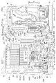
1.車両用駆動装置の全体構成
図1は、本実施形態に係る車両用駆動装置1の概略構成を示す模式図である。図1に示すように、この車両用駆動装置1は、回転電機MGと、トルクコンバータTCと、回転電機MG及びトルクコンバータTCを収容するケース3(図2参照)と、を備えている。トルクコンバータTCは、回転電機MGに駆動連結されており、具体的には、回転電機MGと出力部材Oとの間の動力伝達経路に設けられている。出力部材Oは、出力用差動歯車装置DFを介して車輪Wに駆動連結されており、出力部材Oに伝達された回転及びトルクは、出力用差動歯車装置DFを介して左右2つの車輪Wに分配されて伝達される。これにより、車両用駆動装置1は、回転電機MGのトルクを車輪Wに伝達させて車両を走行させることができる。本実施形態では、トルクコンバータTCが本発明における「流体継手」に相当する。
1. 1 is a schematic diagram showing a schematic configuration of a vehicle drive device 1 according to the present embodiment. As shown in FIG. 1, the vehicle drive device 1 includes a rotating electrical machine MG, a torque converter TC, and a case 3 (see FIG. 2) that houses the rotating electrical machine MG and the torque converter TC. The torque converter TC is drivingly connected to the rotating electrical machine MG, and specifically, provided in a power transmission path between the rotating electrical machine MG and the output member O. The output member O is drivingly connected to the wheel W via the output differential gear device DF, and the rotation and torque transmitted to the output member O are transmitted to the left and right wheels via the output differential gear device DF. It is distributed to W and transmitted. Thereby, the vehicle drive device 1 can drive the vehicle by transmitting the torque of the rotating electrical machine MG to the wheels W. In the present embodiment, the torque converter TC corresponds to a “fluid coupling” according to the present invention.
本実施形態に係る車両用駆動装置1は、内燃機関Eのトルクを車輪Wに伝達させて車両を走行させることも可能に構成されている。すなわち、車両用駆動装置1は、内燃機関Eに駆動連結される入力部材Iを備えており、図1に示すように、内燃機関Eと車輪Wとを結ぶ動力伝達経路において、内燃機関Eの側から順に、入力部材I、回転電機MG、トルクコンバータTC、及び出力部材Oが設けられている。これにより、本実施形態に係る車両用駆動装置1は、車輪Wの駆動力源として内燃機関E及び回転電機MGの一方又は双方を用いるハイブリッド車両用の駆動装置(ハイブリッド駆動装置)、具体的には、いわゆる1モータパラレル方式のハイブリッド駆動装置として構成されている。 The vehicle drive device 1 according to the present embodiment is configured such that the vehicle can travel by transmitting the torque of the internal combustion engine E to the wheels W. In other words, the vehicle drive device 1 includes an input member I that is drivingly connected to the internal combustion engine E. As shown in FIG. 1, in the power transmission path that connects the internal combustion engine E and the wheels W, In order from the side, an input member I, a rotating electrical machine MG, a torque converter TC, and an output member O are provided. Thus, the vehicle drive device 1 according to the present embodiment is a hybrid vehicle drive device (hybrid drive device) that uses one or both of the internal combustion engine E and the rotating electrical machine MG as a drive force source for the wheels W, specifically, Is configured as a so-called one-motor parallel type hybrid drive device.
なお、内燃機関Eは、機関内部における燃料の燃焼により駆動されて動力を取り出す原動機であり、例えばガソリンエンジンやディーゼルエンジン等を用いることができる。また、本実施形態では、入力部材IはダンパDm(図2参照、図1では省略)を介して内燃機関Eの出力軸(クランクシャフト等)に駆動連結されている。入力部材Iが、ダンパDmを介さずに内燃機関Eの出力軸に駆動連結された構成とすることもできる。 Note that the internal combustion engine E is a prime mover that is driven by combustion of fuel inside the engine to extract power, and for example, a gasoline engine or a diesel engine can be used. In the present embodiment, the input member I is drivingly connected to the output shaft (crankshaft or the like) of the internal combustion engine E via a damper Dm (see FIG. 2, omitted in FIG. 1). The input member I may be drivingly connected to the output shaft of the internal combustion engine E without using the damper Dm.
本実施形態では、図1に示すように、動力伝達経路における入力部材Iと回転電機MGとの間には、車輪Wから内燃機関Eを切り離す内燃機関切離用クラッチとして機能する第一クラッチC1が配置されている。また、動力伝達経路におけるトルクコンバータTCと出力部材Oとの間には、変速機構TMが配置されている。変速機構TMは、変速比を段階的に或いは無段階に変更可能な機構(例えば自動有段変速機構や無段変速機構等)で構成され、中間軸M(変速入力軸)の回転速度を所定の変速比で変速して出力部材O(変速出力軸)へ伝達する。 In the present embodiment, as shown in FIG. 1, a first clutch C1 that functions as an internal combustion engine disconnecting clutch that disconnects the internal combustion engine E from the wheel W between the input member I and the rotating electrical machine MG in the power transmission path. Is arranged. A transmission mechanism TM is disposed between the torque converter TC and the output member O in the power transmission path. The speed change mechanism TM is composed of a mechanism (for example, an automatic stepped speed change mechanism, a continuously variable speed change mechanism, etc.) that can change the speed ratio stepwise or steplessly, and has a predetermined rotational speed of the intermediate shaft M (speed change input shaft). And is transmitted to the output member O (shift output shaft).
本実施形態では、入力部材I、第一クラッチC1、回転電機MG、トルクコンバータTC、変速機構TM、及び出力部材Oは、いずれも軸心X(図2参照)上に配置されており、本実施形態に係る車両用駆動装置1は、FR(Front Engine Rear Drive)方式の車両に搭載される場合に適した一軸構成とされている。 In the present embodiment, the input member I, the first clutch C1, the rotating electrical machine MG, the torque converter TC, the speed change mechanism TM, and the output member O are all disposed on the axis X (see FIG. 2). The vehicle drive device 1 according to the embodiment has a uniaxial configuration suitable for mounting on an FR (Front Engine Rear Drive) type vehicle.
2.駆動装置の各部の構成
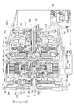
次に、本実施形態に係る車両用駆動装置1の各部の構成について、図2及び図3を参照して説明する。なお、図2は、本実施形態に係る車両用駆動装置1の一部を、軸心Xを含む平面に沿って切断した断面図であり、図3は図2の一部拡大図である。
2. Configuration of Each Part of Drive Device Next, the configuration of each part of the vehicle drive device 1 according to the present embodiment will be described with reference to FIGS. 2 and 3. 2 is a cross-sectional view of a part of the vehicle drive device 1 according to the present embodiment cut along a plane including the axis X, and FIG. 3 is a partially enlarged view of FIG.
2−1.ケース
ケース3は、本実施形態では図2に示すように、第一支持壁部31と、第二支持壁部32と、第三支持壁部33と、周壁部34と、を備えている。周壁部34は、回転電機MG、トルクコンバータTC、及びフレックスプレート8等の外周を覆う概略円筒状に形成されている。また、周壁部34の径内方向R1側に形成されるケース内空間を軸方向Lに区画するように、第二支持壁部32、第一支持壁部31、及び第三支持壁部33が、軸第二方向L2側から記載の順に配置されている。本実施形態では、第一支持壁部31が本発明における「隔壁」に相当する。
2-1. Case In this embodiment, as shown in FIG. 2, the
図2に示すように、ケース3内における第一支持壁部31と第二支持壁部32との間に第一収容室35が形成され、この第一収容室35に回転電機MGが収容されている。本実施形態では、回転電機MGの径内方向R1であって、径方向Rに見て回転電機MGと重複する位置に第一クラッチC1が配置されている。従って、第一クラッチC1も、回転電機MGと共に第一収容室35に収容されている。また、ケース3内における第一支持壁部31と第三支持壁部33との間に第二収容室36が形成され、この第二収容室36にトルクコンバータTC及びフレックスプレート8が収容されている。すなわち、第一収容室35と第二収容室36とは、第一支持壁部31により分離されている。更に、ケース3内における第二支持壁部32より軸第二方向L2側に形成された第三収容室37にダンパDmが収容されている。また、ケース3内における第三支持壁部33より軸第一方向L1側に形成された第四収容室38に変速機構TM(図2では省略)が収容されている。第一収容室35、第二収容室36、第三収容室37、及び第四収容室38は、互いに独立した空間として形成されている。ここで、「互いに独立した空間」とは、互いに油密状に区画されていることを意味する。このような構成は、各部に適宜シール部材を配置することで実現されている。
As shown in FIG. 2, a
本実施形態では、ケース3は、第一ケース部3Aと、当該第一ケース部3Aより軸第一方向L1側に配置される第二ケース部3Bと、に分離可能に構成されている。これらの第一ケース部3Aと第二ケース部3Bとは、図示しないボルトに等により接合部3Cにおいて互いに連結されて固定されている。第一ケース部3Aは、第一支持壁部31と第二支持壁部32とを有し、第一ケース部3Aのみにより第一収容室35が形成されている。本実施形態では、更に、第一ケース部3Aにより第三収容室37も形成されている。また、第二ケース部3Bは、第三支持壁部33を有し、第二ケース部3Bにより第四収容室38が形成されている。トルクコンバータTCが収容される第二収容室36は、第一ケース部3Aと第二ケース部3Bとが協働して形成されている。
In the present embodiment, the
第一支持壁部31は、回転電機MGが収容された第一収容室35とトルクコンバータTCが収容された第二収容室36とを軸方向Lに分離するように、軸方向Lにおける回転電機MGとトルクコンバータTCとの間で、径方向Rに延びるように形成されている。本実施形態では、第一支持壁部31は、径方向Rに加えて周方向にも延びる円板状の壁部とされており、径方向Rの中心部に、軸方向Lに貫通する貫通孔である第一貫通孔42が形成されている。
The first
第一支持壁部31は、軸第二方向L2側に向かって突出する第一筒状突出部40を備えている。本実施形態では、第一筒状突出部40は、第一支持壁部31の径方向Rの中心部において、軸心Xと同軸に配置されており、第一筒状突出部40の内周面43が、上記第一貫通孔42の外縁部を形成している。すなわち、第一筒状突出部40は、第一支持壁部31の径内方向R1側の端部に形成され、回転電機MGと同軸に配置されて、軸方向Lに突出する筒状部(ボス部)とされている。第一筒状突出部40は、後述するロータ部材21より径内方向R1側であって、径方向Rに見てロータ部材21と重複する部分を有する位置に配置されている。そして、第一筒状突出部40の径内方向R1側に、すなわち、第一貫通孔42の内部に、後述する連結部材9の円筒状部9Aが配置されている。また、第一筒状突出部40の内周面43は、軸第二方向L2側から軸第一方向L1側へ向かうに従って段階的に直径が拡大する階段状内周面とされており、ここでは、最も小径の部分を第一内周面43A、中間の径の部分を第二内周面43B、最も大径の部分を第三内周面43Cとする。
The 1st
また、第一支持壁部31は、第一筒状突出部40よりも大径の第二筒状突出部41を備えている。第二筒状突出部41は、第一筒状突出部40と同じく、軸第二方向L2側に向かって突出するように形成されているとともに、軸心Xと同軸に配置されている。図3に示すように、第二筒状突出部41の突出長さは第一筒状突出部40の突出長さより小さい。また、第二筒状突出部41は、第一筒状突出部40より径方向Rの厚さが小さく形成されている。第二筒状突出部41の内周面41Aには、軸第二方向L2側を向く面(本例では円環状面)を有する内周段差部41Bが形成されている。そして、内周面41Aは、内周段差部41Bを境界として、当該内周段差部41Bより軸第二方向L2側の部分が大径部とされ、当該内周段差部41Bより軸第一方向L1側の部分が小径部とされている。
The
第二支持壁部32は、図2に示すように、回転電機MGより軸第二方向L2側(本例では、軸方向Lにおける回転電機MGとダンパDmとの間)において径方向Rに延びるように形成されている。本実施形態では、第二支持壁部32は、径方向Rに加えて周方向にも延びる円板状の壁部とされており、径方向Rの中心部に軸方向Lの貫通孔である第二貫通孔32Aが形成されている。この第二貫通孔32Aに、入力部材Iが挿通されている。第二支持壁部32は、径内方向R1側の部分が全体として径外方向R2側の部分よりも軸第一方向L1側に位置するように、軸方向Lにオフセットされた形状を有している。
2, the second
第三支持壁部33は、図2に示すように、トルクコンバータTCより軸第一方向L1側(本例では、軸方向LにおけるトルクコンバータTCと変速機構TM(図1参照)との間)において径方向Rに延びるように形成されている。本実施形態では、第三支持壁部33は、径方向Rに加えて周方向にも延びる平坦な円板状の壁部とされており、径方向Rの中心部に軸方向Lの貫通孔である第三貫通孔33Aが形成されている。この第三貫通孔33Aに、中間軸Mが挿通されている。第三支持壁部33には、油圧ポンプ33Bが設けられており、油圧ポンプ33Bを駆動するポンプ駆動軸67は、トルクコンバータTCの後述するポンプインペラ61と一体回転するように駆動連結されている。これにより、ポンプインペラ61の回転に伴い、油圧ポンプ33Bは油を吐出し、車両用駆動装置1の各部に油を供給するための油圧を発生させる。なお、ポンプ駆動軸67は、第九軸受79(本例ではニードルベアリング)及びポンプケースを介して、第三支持壁部33に対して回転可能な状態で径方向Rに支持されている。
As shown in FIG. 2, the
2−2.回転電機
回転電機MGは、図2に示すように、軸方向Lにおける第一支持壁部31と第二支持壁部32との間に形成された第一収容室35に配置されている。本実施形態では、第一収容室35は、第一支持壁部31と第二支持壁部32とにより軸方向Lの両側を区画され、周壁部34により径外方向R2側を区画されている。そして、第一収容室35内には油が供給されるように構成されており、当該油により回転電機MGが冷却される。すなわち、第一収容室35には、回転電機MGの冷却に用いられる油が存在する。
2-2. As shown in FIG. 2, the rotating electrical machine MG is disposed in a
回転電機MGは、図2に示すように、ケース3に固定されたステータStと、ロータ部材21と、を備えている。ステータStは、軸方向Lの両側にコイルエンド部Ceを備えている。ロータ部材21は、ロータ本体Roと、当該ロータ本体Roから径内方向R1側に延びて当該ロータ本体Roを支持するロータ支持部材22と、を備えている。ロータ本体Roは、ステータStの径内方向R1側に配置されるとともに、当該ロータ本体Roと一体回転するロータ支持部材22を介して、ケース3に対して回転可能に支持されている。
As shown in FIG. 2, the rotating electrical machine MG includes a stator St fixed to the
図3に示すように、ロータ支持部材22は、ロータ本体Roを径内方向R1側から支持する部材であり、本実施形態では、ロータ本体Roを保持するロータ保持部25と、径方向延在部26と、を備えている。ロータ保持部25は、軸心Xと同軸に配置され、ロータ本体Roの内周面に接する筒状部及びロータ本体Roの軸第二方向L2側の端面に接するフランジ部を有する円筒状に形成されている。径方向延在部26は、ロータ保持部25と一体的に形成され、ロータ保持部25の軸方向Lの中央部に対して軸第一方向L1側の部分から径内方向R1側に延びるように形成されている。径方向延在部26は、径方向Rに加えて周方向にも延びる円環板状部とされている。本実施形態では、径方向延在部26は、径方向Rに平行に延びるとともに、径内方向R1側の端部が、第一筒状突出部40の外周面に対して径外方向R2側に位置するように形成されている。なお、本実施形態では、径方向延在部26の径内方向R1側の端部(本例では、後述する第二軸方向突出部24の内周面)と、第一筒状突出部40の外周面との間の径方向Rの隙間には、第一スリーブ部材101が配置されている。この第一スリーブ部材101は、当該隙間を油が軸方向Lに流通することを規制するために設けられている。
As shown in FIG. 3, the
径方向延在部26は、軸第一方向L1側に向かって突出する筒状の突出部である第一軸方向突出部23を備えている。第一軸方向突出部23は、軸心Xと同軸に配置され、本実施形態では、径方向延在部26の径内方向R1側の端部において、径方向延在部26と一体的に形成されている。第一軸方向突出部23は、径方向Rにおける第一筒状突出部40と第二筒状突出部41との間において、径方向Rに見て第二筒状突出部41と重複する部分を有する位置に配置されている。そして、第一軸方向突出部23の外周面と第二筒状突出部41の内周面41Aとの間に、ロータ部材21をケース3に支持するための第五軸受75が配置されている。また、径方向延在部26は、軸第二方向L2側に向かって突出する筒状の突出部である第二軸方向突出部24を備えている。第二軸方向突出部24は、軸心Xと同軸に配置され、本実施形態では、径方向延在部26の径内方向R1側の端部において、径方向延在部26と一体的に形成されている。第二軸方向突出部24の軸第二方向側の先端部24Aは、第一筒状突出部40の先端部40Aより軸第二方向L2側に位置する。
The
ロータ支持部材22には、板状部材27が取り付けられている。板状部材27は、径方向Rに加えて周方向にも延びる円環板状部材とされている。そして、本実施形態では、図3に示すように、ロータ保持部25における軸方向Lの中央部よりも軸第二方向L2側の部分の内周面に対して、板状部材27の外周面が嵌合(本例ではスプライン嵌合)するように設けられている。これにより、板状部材27はロータ支持部材22と一体回転する。これにより、ロータ保持部25の径内方向R1側には、ロータ保持部25により径外方向R2側を区画されるとともに、軸方向Lの両側を径方向延在部26と板状部材27とにより区画された空間が形成される。この空間は、各部に適宜配置されたシール部材等により油密状に区画された空間とされ、この空間内に、後述する第一クラッチC1の作動油圧室H1と循環油圧室H2とが形成されている。
A plate-
本実施形態では、板状部材27は、径内方向R1側の部分が全体として径外方向R2側の部分よりも軸第二方向L2側に位置するように、軸方向Lにオフセットされた形状を有している。板状部材27における径内方向R1側の端部には、径外方向R2側の部分に比べて軸方向Lの厚さが大きい肉厚部28が形成されている。この肉厚部28の外周面と第二支持壁部32の径内方向R1側の端部の内周面との間に、ロータ部材21をケース3に支持するための第七軸受77が配置されている。
In the present embodiment, the plate-
2−3.第一クラッチ
第一クラッチC1は、入力部材Iとロータ部材21との間の動力伝達経路に設けられて係合の状態を変化させることが可能な装置である。すなわち、第一クラッチC1は、当該第一クラッチC1によって係合される2つの係合部材の係合の状態を、当該2つの係合部材が係合した状態(スリップ係合した状態を含む)と、当該2つの係合部材が係合しない状態(解放した状態)とに切り替え可能に構成されている。そして、当該2つの係合部材が係合した状態では、入力部材Iとロータ部材21との間で駆動力の伝達が行われ、当該2つの係合部材が解放した状態では、入力部材Iとロータ部材21との間で駆動力の伝達が遮断される。
2-3. First clutch The first clutch C <b> 1 is a device that is provided in a power transmission path between the input member I and the
図3に示すように、第一クラッチC1は、軸方向Lにおける径方向延在部26と板状部材27との間に配置されている。すなわち、第一クラッチC1は、ロータ保持部25により径外方向R2側を区画されるとともに、軸方向Lの両側を径方向延在部26と板状部材27とにより区画される油密状の空間に配置されている。また、第一クラッチC1は、ロータ本体Roより径内方向R1側であって、径方向Rに見てロータ本体Roと重複する部分を有する位置に配置されている。本実施形態では、第一クラッチC1は、ロータ本体Roの軸方向Lの中央部領域と径方向Rに見て重なる軸方向Lの位置に配置されている。
As shown in FIG. 3, the first clutch C <b> 1 is disposed between the
本実施形態では、第一クラッチC1は、クラッチハブ51、摩擦部材53、及びピストン54を備え、湿式多板クラッチ機構として構成されている。本実施形態では、ロータ支持部材22のロータ保持部25が、クラッチドラムとして機能する。第一クラッチC1は、摩擦部材53として、対となる入力側摩擦部材と出力側摩擦部材とを有し、入力側摩擦部材はクラッチハブ51の外周部により径内方向R1側から支持され、出力側摩擦部材はロータ保持部25の内周部により径外方向R2側から支持されている。クラッチハブ51における摩擦部材53の保持部を除く部分は、径方向R及び周方向に延びる円環板状部とされ、径内方向R1側の端部が入力部材Iのフランジ部IAに連結(本例では溶接による接合)されている。
In the present embodiment, the first clutch C1 includes a
図4に示すように、第一クラッチC1の作動油圧室H1は、ロータ支持部材22の径方向延在部26及び第二軸方向突出部24と、ピストン54とにより囲まれて形成されている。また、第一クラッチC1の循環油圧室H2は、主に、ロータ支持部材22のロータ保持部25(クラッチドラム)、ロータ支持部材22に取り付けられた板状部材27、及びピストン54等により囲まれて形成され、内部にクラッチハブ51及び摩擦部材53が収容されている。これらの作動油圧室H1と循環油圧室H2とは、ピストン54に対して軸方向Lの両側に分かれて配置されていると共に、シール部材により互いに油密状に区画されている。また、本実施形態では、作動油圧室H1及び循環油圧室H2の双方が、ロータ本体Roより径内方向R1側であって、径方向Rに見てロータ本体Roと軸方向Lの全域で重複する位置に配置されている。
As shown in FIG. 4, the working hydraulic chamber H <b> 1 of the first clutch C <b> 1 is formed by being surrounded by the
付勢部材55は、ピストン54を軸方向Lにおける摩擦部材53側(本例では軸第二方向L2側)に押圧する。これにより、作動油圧室H1内の油圧及び付勢部材55による軸第二方向L2側へのピストン54の押圧力と、循環油圧室H2内の油圧による軸第一方向L1側へのピストン54の押圧力とのバランスにより、第一クラッチC1が係合又は解放される。すなわち、本実施形態では、作動油圧室H1と循環油圧室H2との間の油圧の差(差圧)に応じてピストン54を軸方向Lに沿って摺動させて、第一クラッチC1の係合の状態を制御することができる。後述するように、循環油圧室H2は、基本的に、車両の走行中には所定圧以上の油で満たされた状態となり、当該油により摩擦部材53が冷却される。
The biasing
2−4.トルクコンバータ
トルクコンバータTCは、図2に示すように、回転電機MGに対して軸第一方向L1側に当該回転電機MGと同軸に配置されている。トルクコンバータTCは、軸方向Lにおける第一支持壁部31と第三支持壁部33との間に配置されている。トルクコンバータTCは、回転ハウジング60と、ポンプインペラ61と、タービンランナ62と、ロックアップクラッチとしての第二クラッチC2と、を備えている。
2-4. Torque Converter As shown in FIG. 2, the torque converter TC is disposed coaxially with the rotating electrical machine MG on the first axial direction L1 side with respect to the rotating electrical machine MG. The torque converter TC is disposed between the first
回転ハウジング60は、内側に配置されたポンプインペラ61と一体回転するように連結されている。また、回転ハウジング60には、上述したようにポンプ駆動軸67が一体回転するように連結されている。本実施形態では、これらのポンプインペラ61、回転ハウジング60、及びポンプ駆動軸67によりトルクコンバータTC(流体継手)の入力部材である継手入力部材が構成されている。詳細は後述するが、本実施形態では、回転ハウジング60は、フレックスプレート8及び連結部材9を介してロータ部材21に駆動連結されている。
The
タービンランナ62は中間軸Mに駆動連結されている。このタービンランナ62によりトルクコンバータTC(流体継手)の出力部材である継手出力部材が構成されている。タービンランナ62は、図1に示すように、中間軸M、変速機構TM、出力部材O、及び出力用差動歯車装置DFを介して、車輪Wに駆動連結されている。本実施形態では、タービンランナ62と中間軸Mとは、軸方向Lに相対移動可能であるとともに周方向にある程度のバックラッシ(遊び)を有する状態で一体回転するように、スプライン嵌合により駆動連結されている。
The
回転ハウジング60は、図3に示すように、トルクコンバータTCの本体部となるポンプインペラ61及びタービンランナ62と、第二クラッチC2とを収容するハウジングとなっている。この回転ハウジング60における軸第二方向L2側を向く面が、後述するフレックスプレート8に対向する対向面部63となる。対向面部63は、径方向外側部63Aと、当該径方向外側部63Aに対して径内方向R1側であって軸方向Lにおける回転電機MG側(軸第二方向L2側)に位置する径方向内側部63Bと、径方向Rにおける径方向外側部63Aと径方向内側部63Bとの間で、径方向外側部63Aと径方向内側部63Bとを軸方向Lにつなぐ段差部63Cと、を備えている。対向面部63は、トルクコンバータTCの軸第二方向L2側の面を覆う回転ハウジング60の部分である。対向面部63は、第一支持壁部31との間に軸方向Lの隙間が形成されるように第一支持壁部31とは離間して配置されている。そして、対向面部63と第一支持壁部31との軸方向Lの間に、後述するフレックスプレート8が配置されている。
As shown in FIG. 3, the
径方向外側部63Aは、対向面部63の径外方向R2側の部分であり、径方向R及び周方向に延びるように形成された円環板状部とされている。本実施形態では、径方向外側部63Aは、径方向Rに平行に延びるとともに、径外方向R2側の端部が回転ハウジング60の外周壁面部64に接続されており、径内方向R1側の端部が段差部63Cに接続されている。径方向内側部63Bは、対向面部63の径内方向R1側の部分であり、径方向R及び周方向に延びるように形成された円環板状部とされている。本実施形態では、径方向内側部63Bは、径方向Rに平行に延びるとともに、径外方向R2側の端部が段差部63Cに接続されている。径方向内側部63Bは、径方向外側部63Aに対して軸第二方向L2側に突出して配置されており、この径方向内側部63Bの径外方向R2側の端部と径方向外側部63Aの径内方向R1側の端部とを接続するように円筒状の段差部63Cが形成されている。段差部63Cの軸第一方向L1側端部は径方向外側部63Aに接続されており、段差部63Cの軸第二方向L2側端部は、径方向内側部63Bに接続されている。径方向内側部63Bの軸心部付近には、中央突出部63Dが形成されている。中央突出部63Dは、軸心Xと同軸に配置され、径方向内側部63Bから軸第二方向L2側へ突出する円筒状の突出部とされている。径方向内側部63Bが径方向外側部63Aに対して軸第二方向L2側に配置されたことにより、段差部63Cの径内方向R1側の回転ハウジング60内には空間が形成されている。この空間には第二クラッチC2が配置されている。ここでは、第二クラッチC2は、径方向Rに見て、段差部63Cと重複する部分を有するように、段差部63Cより径内方向R1側の空間に配置されている。
The radially
トルクコンバータTCは、フレックスプレート8の外周側固定部82が固定される継手側連結部65を備えている。継手側連結部65は、軸方向Lに見て回転ハウジング60と重複する部分を有する位置において回転ハウジング60に固定されている。また、継手側連結部65は、径方向Rに見て、段差部63Cと重複する部分を有する位置において径方向外側部63Aに固定されている。そして、継手側連結部65は、フレックスプレート8の外周側固定部82が当接する連結当接面65Aを備えており、この連結当接面65Aに外周側固定部82の当接面が当接した状態で固定される。本実施形態では、継手側連結部65と外周側固定部82との固定は、連結当接面65Aに直交する方向を締結方向Yとし、当該締結方向Yに沿って径外方向R2側から外周側固定部82を貫通する締結ボルト85により行う。この継手側連結部65とフレックスプレート8との固定構造については、後で詳細に説明する。
The torque converter TC includes a joint-
2−5.回転電機とトルクコンバータとの連結構造
回転電機MGとトルクコンバータTCとは、連結部材9及びフレックスプレート8を介して連結されている。より詳しくは、回転電機MGのロータ部材21とトルクコンバータTCの回転ハウジング60とが、連結部材9及びフレックスプレート8を介して連結されている。言い換えると、ロータ部材21と回転ハウジング60とが、フレックスプレート8を介して連結されている構成であって、ロータ部材21とフレックスプレート8とが、連結部材9を介して連結されている。この連結部材9及びフレックスプレート8は、ロータ部材21と回転ハウジング60とが連動して回転するように連結する部材となっている。
2-5. Connection structure of rotating electric machine and torque converter The rotating electric machine MG and the torque converter TC are connected via a connecting
連結部材9は、円筒状に形成された円筒状部9Aと、円筒状部9Aから径外方向R2側へ向かって延びると共にフレックスプレート8の内周側固定部83が固定される第一フランジ部9Bと、第二収容室36内において円筒状部9Aから径外方向R2側へ向かって延びると共にロータ部材21が連結される第二フランジ部9Cと、を備えている。ここで、円筒状部9Aは、軸心Xと同軸に配置され、第一筒状突出部40の径内方向R1側を通って軸方向Lに延びるように形成されている。そして、円筒状部9Aの軸第一方向L1側の端部に第一フランジ部9Bが連結され、この円筒状部9Aの軸第二方向L2側の端部に第二フランジ部9Cが連結されている。本実施形態では、連結部材9は、第一連結部材91と第二連結部材92との2つの部材により構成されており、第一連結部材91が第一フランジ部9Bを備え、第二連結部材92が第二フランジ部9Cを備えている。円筒状部9Aは第一連結部材91の第一円筒状部91Aと第二連結部材92の第二円筒状部92Aとの双方が連結されて構成されている。
The connecting
第一連結部材91は、第一円筒状部91Aと第一フランジ部9Bとを備えている。第一円筒状部91Aは、円筒状に形成され、後述する第二連結部材92の第二円筒状部92Aの径内方向R1側において軸心Xと同軸に配置されている。第一円筒状部91Aの内周面には、締結部材93としてのボルトが締結される雌ねじが形成されている。第一円筒状部91Aの外周面には、スプライン歯と、当該スプライン歯に対して軸第二方向L2側に形成されてスプライン歯の歯底面以下の径の平滑円筒面である当接面とが形成されている。第一円筒状部91Aのスプライン歯が第二円筒状部92Aのスプライン歯と係合することにより第一円筒状部91Aと第二円筒状部92Aとが連結される。この際、第一円筒状部91Aの当接面が第二円筒状部92Aの当接面と当接することにより第一円筒状部91Aと第二円筒状部92Aとの径方向Rの位置関係が規制され、軸心Xと同軸に位置決めされる。
The first connecting
第一フランジ部9Bは、第一円筒状部91Aの軸第一方向L1側の端部から径外方向R2側へ向かって延びると共に周方向にも延びる円環板状部である。ここでは、第一フランジ部9Bは、径外方向R2側へ向かうに従って段階的に軸第一方向L1側へ向かう階段状断面を有する段付円環板状に形成されている。従って、第一円筒状部91Aから径外方向R2側へ延びる第一の円環板状部である内フランジ部9B1と、内フランジ部9B1の径外方向R2側端部から軸第一方向L1側へ向かって延びる円筒状部であるフランジ段差部9B2と、フランジ段差部9B2の軸第一方向L1側端部から径外方向R2側へ延びる第二の円環板状部である外フランジ部9B3と、を備えている。これにより、外フランジ部9B3は、内フランジ部9B1に対して径外方向R2側であって軸第一方向L1側に位置する。そして、外フランジ部9B3は、第一支持壁部31よりもトルクコンバータTC側(軸第一方向L1側)に配置されている。本実施形態では、第一フランジ部9Bにおける外フランジ部9B3が、本発明における「フランジ部」に相当する。
The
そして、第一フランジ部9Bの外フランジ部9B3にフレックスプレート8が固定される。具体的には、フレックスプレート8の内周側固定部83が外フランジ部9B3に固定される。本実施形態では、外フランジ部9B3と内周側固定部83との固定は、軸方向Lに平行な方向に沿って内周側固定部83を貫通するリベット87により行う。また、内周側固定部83の固定及び位置決めのため、外フランジ部9B3には、貫通孔9B3Aと、内周段差部9B3Bとが形成されている。貫通孔9B3Aは、リベット87を貫通させるための孔であって、外フランジ部9B3を軸方向Lに貫通している。内周段差部9B3Bは、フレックスプレート8の内周側固定部83の位置決めのために形成された段差部であり、内周段差部9B3Bの外周面が内周側固定部83の内周面(軸心開口部84の内周面)に当接することにより、内周側固定部83が軸心Xと同軸に位置決めされる。
Then, the flex plate 8 is fixed to the outer flange portion 9B3 of the
また、本実施形態では、第一連結部材91(連結部材9)における外フランジ部9B3よりも回転電機MG側(軸第二方向L2側)の外周面と第一支持壁部31との間に、シール部材94が設けられている。具体的には、第一フランジ部9Bにおけるフランジ段差部9B2の外周面と、それに対向する第一支持壁部31の内周面となる第一筒状突出部40の第三内周面43Cとの間に、シール部材94が配置されている。このような構成とすることにより、連結部材9と第一支持壁部31との間のスペースを有効活用してシール部材94を配置できる。そして、このシール部材94により、連結部材9及びフレックスプレート8を介して回転電機MGとトルクコンバータTCとを連結しつつ、回転電機MGが収容された第一収容室35とトルクコンバータTCが収容された第二収容室36との間の密閉性をシール部材94により確保することができる。これにより、第二収容室36は、第一収容室35に対して油が浸入しないように密閉された状態で区画されている。従って、回転電機MGの冷却等のために第一収容室35内に存在する油が、第二収容室36へ浸入することを抑制できる。
Further, in the present embodiment, the first connecting member 91 (the connecting member 9) has a space between the outer peripheral surface on the rotating electrical machine MG side (second axial direction L2 side) and the first
更に、本実施形態の構成では、第一連結部材91(連結部材9)と第一支持壁部31との軸方向Lに対向する面間に、第一軸受71が配置されている。具体的には、内フランジ部9B1と、それに対向する第一支持壁部31の面との間に、第一軸受71が配置されている。第一軸受71は、第一連結部材91(連結部材9)を第一支持壁部31に対して回転可能な状態で軸第二方向L2側から支持する軸受であり、軸方向Lの荷重を受けることが可能な軸受(本例ではスラスト軸受)が用いられる。ここで、第一支持壁部31に対向する内フランジ部9B1の面は、内フランジ部9B1における軸第二方向L2側を向く面であり、内フランジ部9B1に対向する第一支持壁部31の面は、第一筒状突出部40の第一内周面43Aと第二内周面43Bとの段差部における軸第一方向L1側を向く面である。また、第一フランジ部9Bは、軸心Xと同軸に配置されていると共に内フランジ部9B1から軸第一方向L1側へ突出する円筒状突出部9B4を有している。そして、この円筒状突出部9B4の内周面に中央突出部63Dの外周面が当接する状態で、中央突出部63Dが円筒状突出部9B4に遊嵌している。これにより、中央突出部63Dが、軸心Xと同軸に配置されるように径方向Rに支持されている。
Furthermore, in the structure of this embodiment, the 1st bearing 71 is arrange | positioned between the surfaces which oppose the axial direction L of the 1st connection member 91 (connection member 9) and the 1st
第二連結部材92は、第二円筒状部92Aと第二フランジ部9Cとを備えている。第二円筒状部92Aは、円筒状に形成され、第一連結部材91の第一円筒状部91Aの径外方向R2側において軸心Xと同軸に配置されている。第二円筒状部92Aの内周面には、スプライン歯と、当該スプライン歯に対して軸第二方向L2側に形成されてスプライン歯の歯底面以下の径の平滑円筒面である当接面とが形成されている。第二円筒状部92Aのスプライン歯が第一円筒状部91Aのスプライン歯と係合することにより第二円筒状部92Aと第一円筒状部91Aとが連結される。この際、第二円筒状部92Aの当接面が第一円筒状部91Aの当接面と当接することにより第二円筒状部92Aと第一円筒状部91Aとの径方向Rの位置関係が規制され、軸心Xと同軸に位置決めされる。また、第一円筒状部91Aの外周面と第一筒状突出部40の第一内周面43Aとの間には、第六軸受76と、第二スリーブ部材102とが配置されている。第二スリーブ部材102は、第六軸受76に対して軸第二方向L2側に配置され、ここでは、第一筒状突出部40先端部40Aと径方向Rに見て重複する位置に配置されている。第二スリーブ部材102は、第一円筒状部91Aの外周面と第一筒状突出部40の第一内周面43Aとの隙間において油が軸方向Lに流通することを規制するために設けられている。
The second connecting
また、第二円筒状部92Aは、第一筒状突出部40の径内方向R1側に配置されており、第一筒状突出部40の先端部40Aより軸第二方向L2側まで延びるように形成されている。この第二円筒状部92Aの軸第二方向L2側の端部から径外方向R2側へ延びるように第二フランジ部9Cが形成されている。これにより、第二フランジ部9Cは、第一筒状突出部40よりも軸第二方向L2側に配置されている。この第二フランジ部9Cは、第二円筒状部92Aの軸第二方向L2側の端部から径外方向R2側へ向かって延びると共に周方向にも延びる円環板状部である。また、本実施形態の構成では、第二連結部材92(連結部材9)と第一筒状突出部40との軸方向Lに対向する面間に、第二軸受72が配置されている。具体的には、第二フランジ部9Cと、それに対向する第一筒状突出部40の先端部40Aとの間に、第二軸受72が配置されている。第二軸受72は、第二連結部材92(連結部材9)を第一支持壁部31(第一筒状突出部40)に対して回転可能な状態で軸第一方向L1側から支持する軸受であり、軸方向Lの荷重を受けることが可能な軸受(本例ではスラスト軸受)が用いられる。
The second
第二フランジ部9Cは、第一筒状突出部40より径外方向R2側において、ロータ支持部材22に連結されている。本実施形態では、第二フランジ部9Cの径外方向R2側の端部と、ロータ支持部材22の第二軸方向突出部24の先端部24A(軸第二方向L2側の端部)とが、軸方向Lに相対移動可能な状態で一体回転するように連結(係合)されている。具体的には、第二フランジ部9Cの径外方向R2側の端部は、径外方向R2側に突出する係合片が周方向に複数分散配置された外歯の係合部とされている。また、第二軸方向突出部24の先端部24Aは、当該係合片を挿入可能な周方向の幅及び軸方向Lの長さを有して径方向Rに貫通する貫通孔が周方向に複数(当該係合片と同数)分散配置された、円筒状係合部とされている。本例では、この貫通孔は、第二軸方向突出部24の軸第二方向L2側の端縁に開口するとともに、軸方向Lの長さが上記係合片の軸方向L長さより大きい、径方向Rに見てU字状の貫通孔とされている。このようなスプライン状の係合機構により、第二軸方向突出部24と第二フランジ部9Cとが、軸方向Lに相対移動可能な状態で一体回転するよう連結されており、その結果、ロータ部材21と第二フランジ部9Cとが、言い換えれば、ロータ部材21と連結部材9とが、軸方向Lに相対移動可能な状態で駆動連結されている。
The
上記のとおり、第一連結部材91と第二連結部材92との連結は、軸方向Lに延びるスプライン歯によるスプライン連結であるため、第一連結部材91と第二連結部材92との軸方向Lの相対移動は、当該スプライン連結によっては規制されない。そこで、本実施形態では、第一連結部材91と第二連結部材92との軸方向Lの相対移動を規制する移動規制機構を備えている。ここでは、第二円筒状部92Aの軸第一方向L1側の端面が、第一フランジ部9Bの内フランジ部9B1の軸第二方向L2側の面に当接すると共に、第一円筒状部91Aの内周面に形成された雌ねじ部に締結固定された締結部材93としてのボルトの軸第一方向L1側を向く面が第二円筒状部92Aの軸第二方向L2側を向く面に当接することにより、移動規制機構が構成されている。具体的には、第二円筒状部92Aの内周面に、軸第二方向L2側を向く面(本例では円環状面)を有する内周段差部92A1が形成されている。また、締結部材93(本例ではボルト)は、第一円筒状部91Aの雌ねじ部に締結固定された状態で、第一円筒状部91Aの外周面より径外方向R2側に突出する円環状部93A(本例ではフランジ付ボルトのボルト頭部)を有し、当該円環状部93Aが内周段差部92A1の軸第二方向L2側を向く面に当接することにより、第一連結部材91と第二連結部材92との軸方向Lの相対移動が規制されている。
As described above, since the connection between the first connecting
図2及び図3に示すように、フレックスプレート8は、軸心Xと同軸(回転電機MGと同軸)に配置された円板状の部材であり、ここでは、径方向Rの中心部分に軸方向Lに貫通する軸心開口部84を備えた円環板状に形成されている。本実施形態では、このフレックスプレート8が本発明における「円板状部材」に相当する。図3に示すように、フレックスプレート8は、軸心開口部84の他に、円板状本体部81と外周側固定部82と内周側固定部83とを備えている。
As shown in FIGS. 2 and 3, the flex plate 8 is a disk-like member disposed coaxially with the axis X (coaxial with the rotating electrical machine MG). Here, the flex plate 8 has a shaft at the central portion in the radial direction R. It is formed in an annular plate shape having an axial opening 84 that penetrates in the direction L. In the present embodiment, the flex plate 8 corresponds to a “disk-shaped member” in the present invention. As shown in FIG. 3, the flex plate 8 includes a disk-shaped
円板状本体部81は、軸方向Lにおける回転電機MGとトルクコンバータTCとの間、具体的には軸方向Lにおける第一支持壁部1とトルクコンバータTCとの間に配置され、径方向Rに沿って延びる円板状に形成されている。本実施形態では、円板状本体部81の径外方向R2側に連続して外周側固定部82が設けられていると共に、円板状本体部81の径内方向R1側に連続して内周側固定部83が設けられている。このため、円板状本体部81は、フレックスプレート8における、外周側固定部82及び内周側固定部83に挟まれた径方向Rの中間部分の円環板状の領域とされている。またここでは、円板状本体部81は、内周側固定部83との境界部分に対して径外方向R2側に、環状膨出部81Aを備えている。環状膨出部81Aは、円板状本体部81の他の部分に対して軸第二方向L2側へ向かって断面円弧状に膨出した部分であって、周方向の全域にわたって連続して形成されているため、全体として環状の膨出部となっている。本実施形態では、円板状本体部81は、環状膨出部81A以外の部分は、径方向Rに平行に配置された単調な平面板状とされている。
The disc-shaped
内周側固定部83は、円板状本体部81の径内方向R1側に一体的に形成されたフレックスプレート8の部分である。本実施形態では、内周側固定部83の径内方向R1側となるフレックスプレート8の径方向Rの中心部分に、軸方向Lに貫通する軸心開口部84が設けられている。従って、内周側固定部83は、一定の径方向幅を有する円環板状に形成されており、この軸心開口部84の内周面が、内周側固定部83の内周面となっている。そして、内周側固定部83は、軸方向Lに平行な方向に沿って当該内周側固定部83を貫通するリベット87により、連結部材9に固定される。そこで、本実施形態では、軸心開口部84の内径は、外フランジ部9B3が有する内周段差部9B3Bの外径と一致するように形成されている。そして、軸心開口部84の内周面が内周段差部9B3Bの外周面に当接するように嵌め込まれることにより、内周側固定部83が軸心Xと同軸に位置決めされる。また、内周側固定部83は、当該内周側固定部83を軸方向Lに貫通する貫通孔である内周側貫通孔83Aを備えている。内周側貫通孔83Aは、軸心開口部84が外フランジ部9B3の内周段差部9B3Bに嵌め込まれた状態で、外フランジ部9B3の貫通孔9B3Aと重なる位置に形成されている。そして、リベット87を、軸方向Lに平行な方向に沿って軸心開口部84と貫通孔9B3Aとの双方に挿通し、当該リベット87の一方の端部を変形させることにより、内周側固定部83が第一フランジ部9Bの外フランジ部9B3に固定される。このようにリベット87を用いた固定構造とすることにより、ボルトを用いた固定に比べて、外フランジ部9B3に雌ねじを設ける必要がなく、ボルトに比べて頭部の突出量も少なく押さえることができるので、内周側固定部83と連結部材9との固定部分の軸方向寸法を短く抑えることができる。図3から明らかなように、フレックスプレート8の径内方向R1側では、径外方向R2側に比べて軸方向Lのスペースが少なので、このようなリベット87を用いた構成、車両用駆動装置1の軸方向寸法の短縮には特に有効である。
The inner peripheral
外周側固定部82は、円板状本体部81の径外方向R2側に一体的に形成されたフレックスプレート8の部分である。外周側固定部82は、円板状本体部81に対して傾斜した面に沿って形成されており、具体的には、軸方向Lに回転電機MG側(軸第二方向L2側)からトルクコンバータTC側(軸第一方向L1側)へ向かうに従って径外方向R2側に広がる円錐台面状に形成されている。言い換えると、外周側固定部82は、軸第二方向L2側から軸第一方向L1側へ向かうに従って径外方向R2側に広がる仮想円錐面に沿った形状となるように形成されている。本実施形態では、外周側固定部82は、フレックスプレート8における円板状本体部81よりも径外方向R2側の部分を軸方向Lの一方側(車両用駆動装置1に組み付けた状態で軸第一方向L1側)へ向けて傾斜させるように屈曲させて形成されている。よって、円板状本体部81との境界部分となる屈曲部82Bより径外方向R2側にあって、軸方向Lに回転電機MG側からトルクコンバータTC側へ向かうに従って径外方向R2側に広がる仮想円錐面に平行な円錐台面を構成する部分が、外周側固定部82となっている。そして、この外周側固定部82における、径内方向R1側及び軸第一方向L1側を向く傾斜した面(径方向内側面)が、継手側連結部65の連結当接面65Aに当接する当接面となる。なお、図示の例では、外周側固定部82の径外方向R2側には、外周側固定部82からケース3の内壁面に向かう方向に屈曲された端縁部88が形成されている。
The outer peripheral
ここで、外周側固定部82が固定されるトルクコンバータTCの回転ハウジング60側の部材である継手側連結部65について詳細に説明する。上述したように、継手側連結部65は、外周側固定部82に当接する連結当接面65Aを備えている。この連結当接面65Aは、外周側固定部82に当接するように、外周側固定部82の当接面と位置及び傾斜角度が合致するように形成されている。すなわち、連結当接面65Aは、外周側固定部82と同様に、軸方向Lに回転電機MG側からトルクコンバータTC側へ向かうに従って径外方向R2側に広がる仮想円錐面に平行な面に沿って形成されている。そして、この連結当接面65Aに直交する方向を締結方向Yとし、当該締結方向Yに沿って径外方向R2側から外周側固定部82を貫通する締結ボルト85により、外周側固定部82が継手側連結部65に固定されている。上記のとおり、外周側固定部82の当接面と継手側連結部65の連結当接面65Aとは互いに平行に形成されているので、締結方向Yは、これらの双方の面に直交する方向となっている。
Here, the joint
本実施形態では、継手側連結部65は、回転ハウジング60の周方向に複数(例えば3〜12個)分散して配置されている。そして、複数の継手側連結部65のそれぞれに、締結ボルト85が締結される雌ねじ部が形成されている。具体的には、複数の継手側連結部65のそれぞれは、締結ボルト85が締結される雌ねじ部が形成されたナット部材65Bと、当該ナット部材65Bを締結方向Yに沿った向きに支持する支持部材65Cと、を有して構成されている。ナット部材65Bは、中心部を貫通する雌ねじ部が形成された柱状部材であって、例えば、六角柱や四角柱等の形状とされ、その軸心部に沿って形成された貫通孔の内周面に雌ねじが形成されている。このナット部材65Bにおける径外方向R2側及び軸第二方向L2側を向く傾斜した面(径方向外側面)が、継手側連結部65の連結当接面65Aとなっている。本実施形態のように複数の継手側連結部65が分散配置される構成では、継手側連結部65のそれぞれの連結当接面65Aの面積は狭く限定される。そのため、各継手側連結部65の連結当接面65Aは、外周側固定部82に平行な仮想円錐面に沿った曲面となっている必要はなく、単純な平面とされていてもよい。支持部材65Cは、ナット部材65Bを回転ハウジング60に固定して支持する部材であって、例えば、溶接等によりナット部材65B及び回転ハウジング60に接合されている。そして、支持部材65Cは、ナット部材65Bの雌ねじ部の軸心(ナット部材65Bの軸心)が締結方向Yに平行になるように、ナット部材65Bを支持している。
In the present embodiment, a plurality of joint
フレックスプレート8の外周側固定部82は、継手側連結部65の連結当接面65Aに当接した状態で固定されている。この固定を締結ボルト85により行うため、外周側固定部82には、締結ボルト85が締結方向Yに貫通する貫通孔である外周側貫通孔82Aが設けられている。この外周側貫通孔82Aは、外周側固定部82の周方向に複数分散配置されている。ここでは、外周側貫通孔82Aは、継手側連結部65の雌ねじ部と同数設けられ、複数の継手側連結部65の雌ねじ部のそれぞれに合致する位置に配置されている。そして、締結ボルト85が、締結方向Yに沿って径外方向R2側から外周側固定部82を貫通し、ナット部材65Bに設けられた雌ねじ部に螺合することにより、外周側固定部82が、締結ボルト85の頭部と連結当接面65Aとの間に挟まれ、継手側連結部65に固定される。
The outer peripheral
継手側連結部65は、軸方向Lに見て回転ハウジング60と重複する部分を有する位置において回転ハウジング60に固定されている。本実施形態では、継手側連結部65の全体が軸方向Lに見て回転ハウジング60と重複する位置、すなわち、回転ハウジング60の外周壁面部64の外周面より径内方向R1側の位置に配置されている。そして、継手側連結部65の連結当接面65Aは、当該連結当接面65Aに直交する方向、すなわち締結方向Yに見て、回転電機MGと重複しないように設けられている。本実施形態では、連結当接面65Aは、締結方向Yに見て、第一支持壁部31とも重複しないように設けられている。これにより、連結当接面65Aは、締結方向Yに見て、回転電機MGが収容されている第一収容室35とも重複しないように設けられている。このように構成したことにより、後述する開口部39を設ける際に、回転電機MG及び第一支持壁部31が邪魔にならず、ケース3の周壁面34に開口部39を設けることが容易になっている。従って、当該開口部39を介して締結ボルト85を挿入し、当該締結ボルト85により外周側固定部82と継手側連結部65との締結固定を行う際にも、外周側固定部82の径外方向R2側から、更にはケース3の外側から締結固定作業を容易に行うことができる。
The joint-
ケース3の周壁面34には、締結ボルト85の挿入及び締結固定作業を行うための開口部39が設けられている。ここでは、開口部39は、トルクコンバータTCが収容された第二収容室36の径外方向R2側を囲む周壁面34における、連結当接面65Aに直交する方向(締結方向Y)に見て連結当接面65Aと重複することがある部分に設けられている。上記のとおり、継手側連結部65は、回転ハウジング60の周方向に複数分散して配置されている。そのため、継手側連結部65が回転ハウジング60の回転方向のいずれの位置にあるかによって、連結当接面65Aと重複する周壁部34の部分は変化する。そこで、開口部39は、締結方向Yに見て連結当接面65Aと重複することがある部分、すなわち、回転ハウジング60と共に継手側連結部65を回転させた場合に、いずれかの回転方向の位置において、締結方向Yに見て連結当接面65Aと重複する部分に設けられている。
The peripheral wall surface 34 of the
本実施形態では、ケース3は、第一ケース部3Aと第二ケース部3Bとに分離可能に構成されている。そして、周壁面34における締結方向Yに見て連結当接面65Aと重複することがある部分は、第一ケース部3Aの周壁面34となる。すなわち、開口部39は、第一ケース部3Aにおける第二収容室36を構成する部分の周壁面34に形成されている。この開口部39は、ケース3の外部から締結方向Yに見て、連結当接面65Aの全体が見えるような位置及び大きさに形成されている。また、本実施形態では、ケース3の周壁面34における周方向の異なる位置に2つの開口部39が形成されている。これは、1つの開口部39から締結ボルト85の締結作業を行う際に、別の開口部39から挿入した工具等により回転ハウジング60が回転しないように規制できるようにするためである。これら開口部39のそれぞれが、蓋部材89により閉塞されている。ここでは、蓋部材89は、金属板の成形体で構成され、開口部39の内周壁及び開口部39の周囲の周壁面34との当接部にはシール部材が設けられている。
In the present embodiment, the
3.各構成部材の支持構造
次に、本実施形態に係る車両用駆動装置1における各構成部材の支持構造について説明する。
3. Next, the support structure of each component in the vehicle drive device 1 according to the present embodiment will be described.
3−1.径方向の支持構造
図2及び図3に示すように、車両用駆動装置1は、ロータ部材21を径方向Rに支持する軸受として、第五軸受75と第七軸受77とを備えており、ロータ部材21はこれらの第五軸受75及び第七軸受77により、軸方向Lの両側で径方向Rに支持されている。第五軸受75は、ロータ部材21を第一支持壁部31に対して回転可能な状態で径方向Rに支持する軸受であり、径方向Rの荷重を受けることが可能なラジアル軸受(本例ではボールベアリング)が用いられる。第七軸受77は、ロータ部材21を第二支持壁部32に対して回転可能な状態で径方向Rに支持する軸受であり、径方向Rの荷重を受けることが可能なラジアル軸受(本例ではボールベアリング)が用いられる。
3-1. Radial Support Structure As shown in FIGS. 2 and 3, the vehicle drive device 1 includes a
本実施形態では、第五軸受75は、第一支持壁部31の第二筒状突出部41の内周面41Aと、ロータ支持部材22の第一軸方向突出部23の外周面とに接するように配置されている。これにより、ロータ部材21は、第五軸受75を介して、第二筒状突出部41の内周面41Aに支持されている。なお、第一クラッチC1は、軸方向Lに見てこの第五軸受75と重複する部分を有する位置に配置されている。具体的には、クラッチハブ51の径外方向R2側部分と当該クラッチハブ51に支持される摩擦部材53の径内方向R1側部分とが、第五軸受75と同じ径方向Rの位置に配置されている。本実施形態では、第七軸受77は、第二支持壁部32の内周面と、ロータ支持部材22に取り付けられた板状部材27の肉厚部28の外周面とに接するように配置されている。これにより、ロータ部材21は、板状部材27及び第七軸受77を介して、第二支持壁部32に支持されている。
In the present embodiment, the
また、第七軸受77より径内方向R1側には、入力部材Iを第二支持壁部32に対して回転可能な状態で径方向Rに支持する第八軸受78(本例ではニードルベアリング)が配置されている。第八軸受78は、入力部材Iの外周面と、板状部材27の肉厚部28の内周面とに接するように配置されており、入力部材Iは、第八軸受78に加えて当該肉厚部28及び第七軸受77を介して、第二支持壁部32に支持されている。
Further, an eighth bearing 78 (in this example, a needle bearing) that supports the input member I in the radial direction R while being rotatable with respect to the second
また、車両用駆動装置1は、第六軸受76と第九軸受79(図2参照)とを備えており、トルクコンバータTC及び連結部材9が、これらの第六軸受76及び第九軸受79により、軸方向Lの両側で径方向Rに支持されている。第六軸受76は、図3に示すように、連結部材9を第一支持壁部31に対して回転可能な状態で径方向Rに支持する軸受であり、径方向Rの荷重を受けることが可能なラジアル軸受(本例ではニードルベアリング)が用いられる。本実施形態では、第六軸受76は、第一筒状突出部40の内周面43と、第二円筒状部92Aの外周面とに接するように配置されている。これにより、トルクコンバータTCの回転ハウジング60が、連結部材9及びフレックスプレート8を介して、第一支持壁部31に支持されている。
In addition, the vehicle drive device 1 includes a
3−2.軸方向の支持構造
図2及び図3に示すように、車両用駆動装置1は、連結部材9を第一支持壁部31に対して軸方向Lに支持する軸受として、第一軸受71と第二軸受72とを備えている。第一軸受71は、連結部材9を第一支持壁部31に対して回転可能な状態で軸第二方向L2側から支持する軸受であり、軸方向Lの荷重を受けることが可能な軸受(本例ではスラスト軸受)が用いられる。第二軸受72は、連結部材9を第一支持壁部31に対して回転可能な状態で軸第一方向L1側から支持する軸受であり、軸方向Lの荷重を受けることが可能な軸受(本例ではスラスト軸受)が用いられる。本実施形態では、図3に示すように、第一軸受71は、第一フランジ部9Bの内フランジ部9B1を軸第二方向L2側から支持し、第二軸受72は第二フランジ部9Cを軸第一方向L1側から支持している。そのため、第一軸受71は、内フランジ部9B1と、それに対向する第一支持壁部31の面との間に配置されている。また、第二軸受72は、第二フランジ部9Cと、それに対向する第一筒状突出部40の先端部40Aとの間に配置されている。
3-2. Axial Support Structure As shown in FIGS. 2 and 3, the vehicle drive device 1 includes a
本実施形態では、更に、軸方向Lにおける第二フランジ部9Cと入力部材Iのフランジ部IAとの間に、軸方向Lの荷重を受けることが可能な第三軸受73(本例ではスラスト軸受)が配置されているとともに、軸方向Lにおける入力部材Iのフランジ部IAと板状部材27の肉厚部28との間に、軸方向Lの荷重を受けることが可能な第四軸受74(本例ではスラスト軸受)が配置されている。
In the present embodiment, a third bearing 73 (in this example, a thrust bearing) that can receive a load in the axial direction L between the
4.第一収容室内の油の流れ
次に、本実施形態に係る車両用駆動装置1における、回転電機MGが収容される第一収容室3内の油の流れについて、図4を用いて説明する。本実施形態では、第一クラッチC1の摩擦部材53を冷却するために循環油圧室H2を循環した後の油が、回転電機MGに供給されて回転電機MGの冷却も行う構成となっている。なお、本実施形態では、図2に示すように、車両用駆動装置1は、第一油圧制御装置103と第二油圧制御装置104の2つの油圧制御装置を備えている。これらの油圧制御装置は、油圧ポンプ33Bから供給された油の油圧を調整又は制御し、車両用駆動装置1の各部に供給する。ここで、第一油圧制御装置103は、変速機構TM(図1参照)が収容される第四収容室38の下方に配置され、主に変速機構TM及びトルクコンバータTCの各部への油圧供給を制御する。第二油圧制御装置104は、第一油圧制御装置103よりも回転電機MG側(軸第二方向L2側)に配置され、主に回転電機MG及び第一クラッチC1の各部への油圧供給を制御する。以下、順に説明する。
4). Next, the flow of oil in the
4−1.クラッチへの油の供給構造
図4に示すように、第一支持壁部31の内部に、第一油路A1と第二油路A2とが形成されている。第一油路A1は、第一クラッチC1の作動油圧室H1に連通し、当該作動油圧室H1にピストン54の作動用の油を供給するための油供給路である。この第一油路A1には、第二油圧制御装置104(図2参照)において、第一クラッチC1の作動用に制御された油圧が供給される。本実施形態では、第一油路A1は、第一支持壁部31の内部を径内方向R1側へ向かって延びた後、第一筒状突出部40の内部を軸第二方向L2側に向かって延びるように形成されている。この第一油路A1は、第一筒状突出部40の先端部40Aにおいて閉塞部材40Cにより閉塞されていると共に、第一油路A1から径外方向R2側へ向かって第一筒状突出部40を径方向Rに貫通するように形成された径方向連通孔40Bと、第一スリーブ部材101を径方向Rに貫通するように形成された径方向連通孔101Aと、ロータ支持部材22の第二軸方向突出部24を径方向Rに貫通するように形成された貫通孔24Bを介して、作動油圧室H1に連通している。
4-1. Structure for Supplying Oil to Clutch As shown in FIG. 4, a first oil passage A <b> 1 and a second oil passage A <b> 2 are formed inside the first
第二油路A2は、第一クラッチC1の循環油圧室H2に連通し、当該循環油圧室H2に摩擦部材53の冷却用の油を供給する。本実施形態では、循環油圧室H2を循環した後の油は回転電機MGに給されて回転電機MGの冷却を行うように構成されている。従って、第二油路A2は、第一クラッチC1の摩擦部材53及び回転電機MGの冷却用の油を供給するための油供給路となっている。この第二油路A2には、第二油圧制御装置104(図2参照)において、循環油圧室H2の循環及び回転電機MGの冷却用に制御(調整)された油圧が供給される。本実施形態では、第二油路A2は、第一支持壁部31の内部を径内方向R1側へ向かって延びた後、第一筒状突出部40の内部を軸第二方向L2側に向かって延びるように形成されている。この第二油路A2は、第一筒状突出部40の先端部40Aにおいて開口する先端開口部A2Aを有している。第二油路A2の先端開口部A2Aは、連結部材9の第二フランジ部9Cと第一筒状突出部40の先端部40Aとの間に形成された軸方向Lの隙間に向かって開口している。また、第二軸方向突出部24の先端部24Aと連結部材9の第二フランジ部9Cとの連結部分には、当該第二軸方向突出部24を径方向Rに貫通する隙間が形成されている。これら2つの隙間を介して、第二油路A2が循環油圧室H2に連通している。
The second oil passage A2 communicates with the circulation hydraulic chamber H2 of the first clutch C1, and supplies cooling oil for the
本実施形態では、第八軸受78はある程度の液密性が確保可能に構成されたシール機能付軸受(ここでは、シールリング付ニードルベアリング)とされている。また、第一筒状突出部40の内周面は第二スリーブ部材102及びシール部材105を介して周方向全体に亘って連結部材9の円筒状部9Aの外周面に接している。そのため、循環油圧室H2は液密状態とされ、第二油路A2から油が供給されることにより、循環油圧室H2は基本的には油で満たされた状態となる。これにより、循環油圧室H2に満たされる多量の油で第一クラッチC1の摩擦部材53を効果的に冷却することが可能となっている。
In the present embodiment, the
具体的には、第二油路A2から循環油圧室H2に供給された油は、図4において破線矢印で示すように、まずクラッチハブ51及び摩擦部材53の軸第一方向L1側を径外方向R2側へ向かって流れる。その後、油は、摩擦部材53を冷却しながら、複数の摩擦部材53の間の隙間、摩擦部材53の外周部とクラッチドラムとして機能するロータ保持部25の内周面部とに形成された軸方向Lに延びる外側スプライン係合部5Aの隙間、及び摩擦部材53の内周部とクラッチハブ51の外周面部とに形成された軸方向Lに延びる内側スプライン係合部5Bの隙間などを通って軸第二方向L2側へ向かって流れる。この際、本実施形態では、ピストン54に連通孔54Aが設けられているので、油が連通孔54Aを通って外側スプライン係合部5Aの隙間に導かれる。このような連通孔54Aを設けない場合には、複数の摩擦部材53の間の隙間を通って径外方向R2側へ流れた油のみが外側スプライン係合部5Aの隙間を軸方向Lに流れることになる。これに比べて、連通孔54Aを設けたことにより、外側スプライン係合部5Aの隙間を油の流路として積極的に利用できるようになり、循環油圧室H2内の油の流動性を高めることができる。従って、摩擦部材53の冷却性能を高めることができる。連通孔54Aは、ピストン54における摩擦部材53より軸第一方向L1側の部分において、ピストン54を径方向Rに貫通するように形成されている。本例では、複数の連通孔54が周方向に分散配置されている。
Specifically, the oil supplied from the second oil passage A2 to the circulating hydraulic chamber H2 is first out of the radial direction in the first axial direction L1 side of the
摩擦部材53よりも軸第二方向L2側へ流れた油は、板状部材27とクラッチハブ51及びフランジ部IAとの隙間を径内方向R1側へ向かって流れる。その後、油は、入力部材Iを径方向Rに貫通するように形成された径方向連通孔IBを通って入力部材I及び連結部材9(第二連結部材92)の内部に形成された軸内空間105に流入する。軸内空間105に入った油は、第二油路A2から供給される油圧により押し出され、連結部材9の円筒状部9A(第二連結部材92の第二円筒状部92A、図3参照)を径方向Rに貫通するように形成された径方向連通孔95及び第一筒状突出部40の内周面43(第一内周面43A)と外周面とを連通する排出油路45を通って、第一筒状突出部40の外周面側に排出される。ここで、排出油路45の出口付近となる径外方向R2側部分には、絞り部45Aが形成されている。この絞り部45Aは、循環油圧室H2が油で満たされた状態を維持するために設けられている。すなわち、絞り部45Aは、排出油路45から排出される油の量を規制することにより、油で満たされた空間となる循環油圧室H2、軸内空間105、及びこれらに連通する油路や隙間などの内部の油圧を一定以上に保持し、これらの内部が油で満たされた状態を維持する機能を果たす。このように循環油圧室H2に連通する空間が油で満たされることにより、この空間内に配置された、第一軸受71、第二軸受72、第三軸受73、第四軸受74、第六軸受76、及び第八軸受78は、油により適切に潤滑される。ここで、第一軸受71よりも軸第一方向L1側において、連結部材9と第一支持壁部31との間を密封するシール部材94が設けられているので、第一軸受71を潤滑した後の油がトルクコンバータTC側の第二収容室36に浸入することは規制されている。
The oil that has flowed from the
排出油路45から排出された油は、第一筒状突出部40の外周面とロータ支持部材22の第一軸方向突出部23の内周面との隙間に供給される。その後、油は、第五軸受75を潤滑しつつ第五軸受75の内部を通過し、第二筒状突出部41の軸第二方向L2側端面とロータ支持部材22の径方向延在部26の軸第一方向L1側面との隙間を径外方向R2へ向かって流れる。そして、第二筒状突出部41に対して径外方向R2側において、ロータ保持部25の内周面に形成された油捕集部25Aに捕集される。
The oil discharged from the
4−2.回転電機への油の供給構造
本実施形態では、油捕集部25Aに捕集された油が、回転電機MGの冷却のために供給される。油捕集部25Aは、径内方向R1側に開口する円筒状空間を形成する受け面であって、径内方向R1側から供給される油を捕集する部位である。本実施形態では、油捕集部25Aは、ロータ保持部25における径方向延在部26より軸第一方向L1側の部分の円筒状の捕集内周面25Bと、当該捕集内周面25Bの軸第二方向L2端部から周方向の全域において径内方向R1側へ延びる径方向延在部26と、捕集内周面25Bの軸第一方向L1側端部から周方向の全域において径内方向R1側に突出するように形成された内側フランジ部25Cと、により形成されている。
4-2. Oil supply structure to rotating electrical machine In the present embodiment, the oil collected in the
油捕集部25Aに捕集された油は、ロータ部材21の回転で発生する遠心力により、油捕集部25Aに連通すると共に捕集内周面25Bから径外方向R2側へ向かって延びるように形成された第一径方向油路29A又は第二径方向油路29Bに流入する。第一径方向油路29Aに流入した油は、当該第一径方向油路29Aをそのまま径外方向R2側へ通り抜けてステータStの軸第一方向L1側のコイルエンド部Ceに供給される。一方、第二径方向油路29Bに流入した油は、当該第二径方向油路29Bに連通する軸方向油路29C及び第三径方向油路29Dを通ってステータStの軸第二方向L2側のコイルエンド部Ceに供給される。ここで、第一径方向油路29Aは、周方向に複数個(例えば3〜12個)が分散配置されている。第一径方向油路29Aの軸方向Lの位置は、冷却したいコイルエンド部Ceの位置にあわせた配置とされる。
The oil collected in the
第二径方向油路29Bも、第一径方向油路29Aと同数、周方向に分散配置されている。そして、複数の第二径方向油路29Bのそれぞれに対応する周方向の位置に、軸方向油路29C及び第三径方向油路29Dが配置されている。本実施形態では、第二径方向油路29Bは、第一径方向油路29Aとは周方向位置を異ならせて配置されている。なお、図示の例のように、第二径方向油路29Bと第一径方向油路29Aとの軸方向Lの位置が異なっている場合には、第二径方向油路29Bと第一径方向油路29Aとが周方向の同じ位置に配置されていてもよい。軸方向油路29Cは、ロータ本体Roの内周面とロータ保持部25の外周面との当接面に沿って設けられており、ここでは、ロータ保持部25の外周面において軸方向Lに延びるように形成された凹溝により構成されている。第三径方向油路29Dは、ロータ本体Roの軸第二方向L2側の端面を構成するエンドプレートEpとロータ保持部25の軸第二方向L2側の端部から径外方向R2側へ延出する外側フランジ部25Dとの当接面に沿って設けられており、ここでは、外側フランジ部25Dの軸第一方向L1側の面において径方向Rに延びるように形成された凹溝により構成されている。
The same number of second
このような構成とすることにより、油捕集部25Aに一旦捕集した油を周方向に分散配置された第一径方向油路29Aと第二径方向油路29Bとにより分離して、軸第一方向L1のコイルエンド部Ceと軸第二方向L2側のコイルエンド部Ceとのそれぞれに冷却用の油を供給することができる。これにより、ステータStの軸方向Lの両側のコイルエンド部Ceを均等に冷却することができる。
By adopting such a configuration, the oil once collected in the
5.その他の実施形態
最後に、本発明に係る車両用駆動装置の、その他の実施形態について説明する。なお、以下のそれぞれの実施形態で開示される構成は、矛盾が生じない限り、他の実施形態で開示される構成と組み合わせて適用することが可能である。
5. Other Embodiments Finally, other embodiments of the vehicle drive device according to the present invention will be described. Note that the configurations disclosed in the following embodiments can be applied in combination with the configurations disclosed in other embodiments as long as no contradiction arises.
(1)上記の実施形態では、トルクコンバータTCの回転ハウジング60が段差部63Cを備え、継手側連結部65が、段差部63Cに対して径外方向R2側であって径方向Rに見て段差部63Cと重複する部分を有する位置に配置された構成を例として説明した。しかし、本発明の実施形態はこれに限定されない。回転ハウジング60が段差部63Cを備えない構成とし、或いは段差部63Cを備える場合であって継手側連結部65を径方向Rに見て段差部63Cと重複しない位置に配置した構成とすることも、本発明の好適な実施形態の一つである。
(1) In the above-described embodiment, the
(2)上記の実施形態では、フレックスプレート8の外周側固定部82と継手側連結部65とを締結ボルト85により固定する構成を例として説明した。しかし、本発明の実施形態はこれに限定されない。外周側固定部82と継手側連結部65とを、ボルト締結以外の固定方法により固定する構成としてもよい。このような固定方法として、例えば、リベットや溶接などを用いた方法とすることができる。
(2) In the above embodiment, the configuration in which the outer peripheral
(3)上記の実施形態では、フレックスプレート8の内周側固定部83と連結部材9の第一フランジ部9Bとをリベット87により固定する構成を例として説明した。しかし、本発明の実施形態はこれに限定されない。フレックスプレート8と連結部材9とを、リベット固定以外の固定方法により固定する構成としてもよい。このような固定方法として、例えば、ボルトによる締結や溶接などを用いた方法とすることができる。
(3) In the above embodiment, the configuration in which the inner peripheral
(4)上記の実施形態では、フレックスプレート8の内周側固定部83と連結部材9の第一フランジ部9Bとを固定するリベット87を、軸方向Lに平行な方向に沿って配置する構成を例として説明した。しかし、本発明の実施形態はこれに限定されず、リベット87を軸方向Lに対して傾斜した方向に沿って配置した構成とすることも、本発明の好適な実施形態の一つである。
(4) In the above embodiment, the
(5)上記の実施形態では、回転電機MGのロータ部材21とトルクコンバータTCの回転ハウジング60とが、連結部材9及びフレックスプレート8を介して連結されている構成について説明した。しかし、連結部材9を備えることは必須ではなく、ロータ部材21と回転ハウジング60とが、フレックスプレート8のみを介して連結されている構成としても好適である。この場合において、回転電機MGとトルクコンバータTCとの間にケース3の隔壁(第一支持壁部31)が存在する場合には、ロータ部材21が、当該隔壁の径内方向R1側を通ってトルクコンバータTC側へ延在する軸方向延在部を備え、当該軸方向延在部にフレックスプレート8の内周側固定部83が固定される構成とすると好適である。
(5) In the above embodiment, the configuration in which the
(6)上記の実施形態では、連結部材9が、第一筒状突出部40より径外方向R2側まで延びる第二フランジ部9Cを有し、連結部材9とロータ支持部材22との係合部が、第一筒状突出部40より径外方向R2側に位置する構成を例として説明した。しかし、本発明の実施形態はこれに限定されるものではなく、ロータ支持部材22が、第一筒状突出部40より径内方向R1側まで延びる部分を有し、連結部材9とロータ支持部材22との係合部が、第一筒状突出部40より径内方向R1側に位置する構成とすることもできる。このような構成の場合、連結部材9が、上記のように第一連結部材91と第二連結部材92との2つの部材により構成されている必要はなく、第一連結部材91に相当する部材のみにより連結部材9が構成されていても好適である。
(6) In the above embodiment, the connecting
(7)上記の実施形態では、回転電機MGが収容される第一収容室35とトルクコンバータTC及びフレックスプレート8が収容される第二収容室36とが、隔壁としての第一支持壁部31により分離された構成を例として説明した。しかし、本発明の実施形態はこれに限定されない。ケース3が回転電機MGとトルクコンバータTC及びフレックスプレート8との間に隔壁を備えず、同じ室内にこれらを収容した構成とすることも、本発明の好適な実施形態の一つである。
(7) In the above-described embodiment, the
(8)上記の実施形態では、周壁部34における、連結当接面65Aに直交する方向に見て当該連結当接面65Aと重複することがある部分に開口部39が設けられた構成を例として説明した。しかし、本発明の実施形態はこれに限定されない。上述した位置とは異なる周壁部34の位置に開口部39を設けてもよいし、フレックスプレート8と継手側連結部65とを固定する作業を行うための開口部39をケース3に設けない構成としてもよい。
(8) In the above embodiment, an example in which the
(9)上記の実施形態では、車両用駆動装置1が一軸構成とされている場合を例として説明した。しかし、本発明の実施形態はこれに限定されるものではなく、車両用駆動装置1を、例えばカウンタギヤ機構等を備えた複軸構成の駆動装置とすることもできる。このような構成は、FF(Front Engine Front Drive)方式の車両に搭載される場合に適している。 (9) In the above-described embodiment, the case where the vehicle drive device 1 has a uniaxial configuration has been described as an example. However, the embodiment of the present invention is not limited to this, and the vehicle drive device 1 may be a multi-shaft drive device including a counter gear mechanism, for example. Such a configuration is suitable when mounted on a FF (Front Engine Front Drive) type vehicle.
(10)上記の実施形態では、車両用駆動装置1が、内燃機関Eに駆動連結される入力部材I、及び第一クラッチC1を備えた構成を例として説明した。しかし、本発明の実施形態はこれに限定されるものではなく、車両用駆動装置1が、入力部材Iや第一クラッチC1を備えない構成とすることも可能である。 (10) In the above-described embodiment, the configuration in which the vehicle drive device 1 includes the input member I that is drivingly connected to the internal combustion engine E and the first clutch C1 has been described as an example. However, the embodiment of the present invention is not limited to this, and the vehicle drive device 1 may be configured not to include the input member I and the first clutch C1.
(11)その他の構成に関しても、本明細書において開示された実施形態は全ての点で例示であって、本発明の実施形態はこれに限定されない。すなわち、本願の特許請求の範囲に記載されていない構成に関しては、本発明の目的を逸脱しない範囲内で適宜改変することが可能である。 (11) Regarding other configurations as well, the embodiments disclosed herein are illustrative in all respects, and embodiments of the present invention are not limited thereto. In other words, configurations that are not described in the claims of the present application can be modified as appropriate without departing from the object of the present invention.
本発明は、回転電機と、当該回転電機に対して当該回転電機の軸方向の一方側に当該回転電機と同軸に配置される流体継手と、を備えた車両用駆動装置に好適に利用することができる。 The present invention is preferably used for a vehicle drive device including a rotating electrical machine and a fluid coupling disposed coaxially with the rotating electrical machine on one side in the axial direction of the rotating electrical machine with respect to the rotating electrical machine. Can do.
1:車両用駆動装置
21:ロータ部材
31:第一支持壁部(隔壁)
34:周壁部
35:第一収容室
36:第二収容室
39:開口部
60:回転ハウジング
63:対向面部
63A:径方向外側部
63B:径方向内側部
63C:段差部
65:継手側連結部
65A:連結当接面
8:フレックスプレート(円板状部材)
81:円板状本体部
82:外周側固定部
83:内周側固定部
85:締結ボルト
87:リベット
89:蓋部材
9:連結部材
9A:円筒状部
9B3:外フランジ部(フランジ部)
94:シール部材
MG:回転電機
TC:トルクコンバータ(流体継手)
Y:締結方向
L:軸方向
R:径方向
1: Vehicle drive device 21: Rotor member 31: First support wall (partition wall)
34: peripheral wall portion 35: first storage chamber 36: second storage chamber 39: opening 60: rotating housing 63: facing
81: Disk-shaped main body part 82: Outer peripheral side fixing part 83: Inner peripheral side fixing part 85: Fastening bolt 87: Rivet 89: Lid member 9: Connecting
94: Seal member MG: Rotary electric machine TC: Torque converter (fluid coupling)
Y: fastening direction L: axial direction R: radial direction
Claims (7)
前記回転電機のロータ部材と前記流体継手の回転ハウジングとが、円板状部材を介して連結され、
前記円板状部材は、前記回転電機と同軸に配置されると共に、円板状本体部と、当該円板状本体部の径方向の外側に一体的に形成された外周側固定部と、を備え、
前記円板状本体部は、前記軸方向における前記回転電機と前記流体継手との間に配置され、前記径方向に沿って延びる円板状に形成され、
前記流体継手は、前記円板状部材の外周側固定部が固定される継手側連結部を備え、
前記外周側固定部は、前記軸方向に前記回転電機側から前記流体継手側へ向かうに従って前記径方向の外側に広がる円錐台面状に形成され、
前記継手側連結部は、前記軸方向に見て前記回転ハウジングと重複する部分を有する位置において前記回転ハウジングに固定されていると共に、前記外周側固定部が当接する連結当接面を備え、
前記連結当接面は、当該連結当接面に直交する方向に見て、前記回転電機と重複しないように設けられている車両用駆動装置。 A vehicle drive device comprising: a rotating electrical machine; and a fluid coupling disposed coaxially with the rotating electrical machine on one side in the axial direction of the rotating electrical machine with respect to the rotating electrical machine,
The rotor member of the rotating electrical machine and the rotating housing of the fluid coupling are connected via a disk-shaped member,
The disk-shaped member is disposed coaxially with the rotating electrical machine, and includes a disk-shaped main body portion and an outer peripheral side fixing portion integrally formed on the outer side in the radial direction of the disk-shaped main body portion. Prepared,
The disc-shaped main body portion is disposed between the rotating electrical machine and the fluid coupling in the axial direction, and is formed in a disc shape extending along the radial direction,
The fluid coupling includes a coupling side coupling portion to which an outer peripheral side fixing portion of the disk-shaped member is fixed,
The outer peripheral side fixing portion is formed in a truncated cone shape that extends outward in the radial direction from the rotating electrical machine side to the fluid coupling side in the axial direction,
The joint-side connecting portion is fixed to the rotating housing at a position having a portion overlapping with the rotating housing when viewed in the axial direction, and includes a connecting contact surface with which the outer peripheral side fixing portion contacts,
The connecting contact surface is a vehicle drive device provided so as not to overlap with the rotating electrical machine when viewed in a direction orthogonal to the connecting contact surface.
前記第一収容室には、前記回転電機の冷却に用いられる油が存在し、
前記連結当接面は、当該連結当接面に直交する方向に見て、前記第一収容室と重複しないように設けられている請求項1に記載の車両用駆動装置。 The rotating electrical machine is housed in a first housing chamber, the fluid coupling and the disc-shaped member are housed in a second housing chamber separated from the first housing chamber by a partition;
In the first storage chamber, there is oil used for cooling the rotating electrical machine,
2. The vehicle drive device according to claim 1, wherein the connection contact surface is provided so as not to overlap the first storage chamber when viewed in a direction orthogonal to the connection contact surface.
前記第二収容室の前記径方向の外側を囲む周壁部における、前記連結当接面に直交する方向に見て前記連結当接面と重複することがある部分に、開口部が設けられている請求項1又は2に記載の車両用駆動装置。 The rotating electrical machine is housed in a first housing chamber, the fluid coupling and the disc-shaped member are housed in a second housing chamber separated from the first housing chamber by a partition;
An opening is provided in a portion of the peripheral wall that surrounds the outer side of the second storage chamber in the radial direction and may overlap the connection contact surface when viewed in a direction orthogonal to the connection contact surface. The vehicle drive device according to claim 1 or 2.
前記ロータ部材と前記円板状部材とが、連結部材を介して連結され、
前記連結部材は、円筒状に形成された円筒状部と、前記第二収容室内において前記円筒状部から前記径方向の外側へ向かって延びると共に前記円板状部材が固定されるフランジ部を備え、
前記連結部材における前記フランジ部よりも前記回転電機側の外周面と前記隔壁との間に、シール部材が設けられている請求項1から3のいずれか一項に記載の車両用駆動装置。 The rotating electrical machine is housed in a first housing chamber, the fluid coupling and the disc-shaped member are housed in a second housing chamber separated from the first housing chamber by a partition;
The rotor member and the disk-shaped member are connected via a connecting member,
The connecting member includes a cylindrical portion formed in a cylindrical shape, and a flange portion that extends from the cylindrical portion toward the outside in the radial direction in the second storage chamber and to which the disk-shaped member is fixed. ,
The vehicle drive device according to any one of claims 1 to 3, wherein a seal member is provided between an outer peripheral surface of the connecting member closer to the rotating electrical machine than the flange portion and the partition wall.
前記継手側連結部は、前記径方向に見て、前記段差部と重複する部分を有する位置において前記径方向外側部に固定されている請求項1から4のいずれか一項に記載の車両用駆動装置。 The opposing surface portion facing the disk-shaped member in the rotating housing has a radially outer portion and a diameter located on the rotating electrical machine side in the axial direction inside the radial direction with respect to the radially outer portion. A step part connecting the radial inner part and the radial outer part in the axial direction between the radial inner part and the radial inner part and the radial outer part in the radial direction,
5. The vehicle according to claim 1, wherein the joint-side connecting portion is fixed to the radially outer portion at a position having a portion overlapping with the stepped portion when viewed in the radial direction. Drive device.
前記円板状部材は、前記円板状本体部よりも前記径方向の内側に内周側固定部を備え、
前記軸方向に平行な方向に沿って前記内周側固定部を貫通するリベットにより、前記内周側固定部が、前記連結部材に固定されている請求項1から6のいずれか一項に記載の車両用駆動装置。 The rotor member and the disk-shaped member are connected via a connecting member,
The disc-shaped member includes an inner peripheral side fixing portion on the inner side in the radial direction than the disc-shaped main body portion,
The said inner peripheral side fixing | fixed part is fixed to the said connection member by the rivet which penetrates the said inner peripheral side fixing | fixed part along the direction parallel to the said axial direction. Vehicle drive system.
Priority Applications (5)
| Application Number | Priority Date | Filing Date | Title |
|---|---|---|---|
| JP2012017310A JP2013155810A (en) | 2012-01-30 | 2012-01-30 | Vehicle drive device |
| CN201280058252.9A CN104024697A (en) | 2012-01-30 | 2012-12-07 | Vehicle drive device |
| PCT/JP2012/081832 WO2013114731A1 (en) | 2012-01-30 | 2012-12-07 | Vehicle drive device |
| DE112012004669.2T DE112012004669T5 (en) | 2012-01-30 | 2012-12-07 | Vehicle drive device |
| US13/727,152 US20130193816A1 (en) | 2012-01-30 | 2012-12-26 | Vehicle drive device |
Applications Claiming Priority (1)
| Application Number | Priority Date | Filing Date | Title |
|---|---|---|---|
| JP2012017310A JP2013155810A (en) | 2012-01-30 | 2012-01-30 | Vehicle drive device |
Publications (2)
| Publication Number | Publication Date |
|---|---|
| JP2013155810A true JP2013155810A (en) | 2013-08-15 |
| JP2013155810A5 JP2013155810A5 (en) | 2014-05-08 |
Family
ID=48869619
Family Applications (1)
| Application Number | Title | Priority Date | Filing Date |
|---|---|---|---|
| JP2012017310A Pending JP2013155810A (en) | 2012-01-30 | 2012-01-30 | Vehicle drive device |
Country Status (5)
| Country | Link |
|---|---|
| US (1) | US20130193816A1 (en) |
| JP (1) | JP2013155810A (en) |
| CN (1) | CN104024697A (en) |
| DE (1) | DE112012004669T5 (en) |
| WO (1) | WO2013114731A1 (en) |
Cited By (8)
| Publication number | Priority date | Publication date | Assignee | Title |
|---|---|---|---|---|
| JP2015054684A (en) * | 2013-09-13 | 2015-03-23 | トヨタ自動車株式会社 | Power transmission device for hybrid vehicle |
| JP2015081088A (en) * | 2013-10-24 | 2015-04-27 | フォード グローバル テクノロジーズ、リミテッド ライアビリティ カンパニー | Assembly for powertrain of hybrid electric vehicle |
| JP2015081087A (en) * | 2013-10-24 | 2015-04-27 | フォード グローバル テクノロジーズ、リミテッド ライアビリティ カンパニー | Assembly for powertrain of hybrid electric vehicle |
| JP2015174561A (en) * | 2014-03-14 | 2015-10-05 | トヨタ自動車株式会社 | Vehicle drive device and assembly method of the same |
| US9327590B2 (en) | 2014-03-14 | 2016-05-03 | Toyota Jidosha Kabushiki Kaisha | Hybrid vehicle |
| JP2019172006A (en) * | 2018-03-28 | 2019-10-10 | 株式会社エクセディ | Vehicle driving device |
| KR102155634B1 (en) * | 2019-03-29 | 2020-09-14 | 주식회사평화발레오 | Power train apparatus for hybrid vehicle |
| CN113412572A (en) * | 2019-02-14 | 2021-09-17 | Gkn汽车有限公司 | Drive assembly with electric drive and gear mechanism |
Families Citing this family (23)
| Publication number | Priority date | Publication date | Assignee | Title |
|---|---|---|---|---|
| US9579965B2 (en) * | 2012-01-31 | 2017-02-28 | Ford Global Technologies, Llc | Modular powertrain component for hybrid electric vehicles |
| US8960393B2 (en) * | 2012-01-31 | 2015-02-24 | Ford Global Technologies, Llc | Modular powertrain component for hybrid electric vehicles |
| US9180766B2 (en) * | 2013-12-16 | 2015-11-10 | Ford Global Technologies, Llc | Front module for a modular hybrid transmission and a method for connecting/disconnecting the front module from a torque converter |
| WO2015188819A2 (en) * | 2014-06-11 | 2015-12-17 | Schaeffler Technologies AG & Co. KG | Modular housing for a hybrid module |
| JP2016033003A (en) * | 2014-07-29 | 2016-03-10 | アイシン・エィ・ダブリュ株式会社 | Hybrid drive device |
| JP6646430B2 (en) * | 2015-12-16 | 2020-02-14 | ジヤトコ株式会社 | Lock-up clutch piston detent structure |
| CN109642650B (en) * | 2016-08-23 | 2022-01-18 | 舍弗勒技术股份两合公司 | Rotor carrier and flange assembly |
| JP6531133B2 (en) * | 2017-04-27 | 2019-06-12 | 本田技研工業株式会社 | Drive device for hybrid vehicle |
| DE102017213081A1 (en) * | 2017-07-28 | 2019-01-31 | Zf Friedrichshafen Ag | power shift |
| US10752103B2 (en) * | 2017-10-06 | 2020-08-25 | Schaeffler Technologies AG & Co. KG | Motor assembly for hybrid vehicle |
| US10637329B2 (en) * | 2017-11-01 | 2020-04-28 | Schaeffler Technologies AG & Co. KG | Hybrid motor assembly with rotor cooling and method thereof |
| FR3073913A1 (en) * | 2017-11-22 | 2019-05-24 | Valeo Embrayages | TRANSMISSION DEVICE FOR A HYBRID VEHICLE |
| JP6996391B2 (en) | 2018-03-29 | 2022-01-17 | 株式会社アイシン | Drive transmission device and drive device |
| DE102018211377A1 (en) * | 2018-07-10 | 2020-02-13 | Zf Friedrichshafen Ag | Rotor carrier for an electrical machine |
| US10816082B2 (en) * | 2018-07-16 | 2020-10-27 | Borgwarner Inc. | Vehicle driveline component having rotatable lubricant pathway for transmitting lubricating fluid to desired location |
| JP7458697B2 (en) * | 2018-07-17 | 2024-04-01 | 株式会社エクセディ | Power transmission system and damping mechanism |
| US10875399B2 (en) * | 2018-09-28 | 2020-12-29 | Schaeffler Technologies AG & Co. KG | Hybrid module including integrated hydraulics and controls |
| DE102018219676A1 (en) * | 2018-11-16 | 2020-05-20 | Zf Friedrichshafen Ag | Cone element as a coupling in the K0 installation space |
| CN113261182B (en) * | 2019-01-09 | 2024-07-12 | 株式会社爱信 | Driving device for vehicle |
| JP7190557B2 (en) * | 2019-03-29 | 2022-12-15 | 株式会社アイシン | Vehicle drive system |
| IT201900009612A1 (en) * | 2019-06-20 | 2020-12-20 | Dayco Europe Srl | TRANSMISSION MODULE FOR A HYBRID DRIVE VEHICLE |
| US11040611B2 (en) * | 2019-08-27 | 2021-06-22 | GM Global Technology Operations LLC | Turbine mounted P2 front wheel drive transmission arrangement |
| US11451101B2 (en) * | 2021-02-24 | 2022-09-20 | Schaeffler Technologies AG & Co. KG | Electric motor arranged for mounting to a combustion engine |
Citations (7)
| Publication number | Priority date | Publication date | Assignee | Title |
|---|---|---|---|---|
| JPH09503279A (en) * | 1993-10-02 | 1997-03-31 | ツェットエフ、フリードリッヒスハーフェン、アクチエンゲゼルシャフト | Device for transmitting torque from a drive unit to a transmission with a fluid torque converter |
| JP2001241531A (en) * | 2000-02-25 | 2001-09-07 | Nissan Motor Co Ltd | Connecting structure for torque converter case and drive plate |
| JP2003113927A (en) * | 2001-10-03 | 2003-04-18 | Suzuki Motor Corp | Connection part structure of transmission case and motor of motor assist apparatus for vehicle |
| WO2011062264A1 (en) * | 2009-11-19 | 2011-05-26 | アイシン・エィ・ダブリュ株式会社 | Drive device for vehicle |
| WO2011062191A1 (en) * | 2009-11-19 | 2011-05-26 | アイシン精機株式会社 | Vehicle drive device |
| JP2011105187A (en) * | 2009-11-19 | 2011-06-02 | Aisin Seiki Co Ltd | Driving device for hybrid vehicle |
| JP2011105195A (en) * | 2009-11-19 | 2011-06-02 | Aisin Seiki Co Ltd | Drive device for hybrid vehicle |
Family Cites Families (8)
| Publication number | Priority date | Publication date | Assignee | Title |
|---|---|---|---|---|
| JPH0526266Y2 (en) * | 1986-10-17 | 1993-07-02 | ||
| JPH01166852U (en) * | 1988-04-28 | 1989-11-22 | ||
| DE10221625A1 (en) * | 2002-03-26 | 2003-10-16 | Zf Sachs Ag | Device for coupling a housing arrangement of a coupling device with a rotor arrangement of an electric machine |
| WO2009146670A2 (en) * | 2008-06-02 | 2009-12-10 | Luk Lamellen Und Kupplungsbau Beteiligungs Kg | Combined power transmission and drive unit for use in hybrid systems and a hybrid system |
| DE102009040367A1 (en) * | 2008-09-26 | 2010-04-08 | Luk Lamellen Und Kupplungsbau Beteiligungs Kg | Combined power transmission and drive unit for use in hybrid systems and hybrid systems |
| JP5321423B2 (en) * | 2009-11-19 | 2013-10-23 | アイシン精機株式会社 | Hybrid vehicle drive device |
| CN102725161A (en) * | 2010-03-05 | 2012-10-10 | 爱信艾达株式会社 | Vehicle driving apparatus |
| US8770364B2 (en) * | 2012-01-31 | 2014-07-08 | Ford Global Technologies, Llc | Modular powertrain component for hybrid electric vehicles |
-
2012
- 2012-01-30 JP JP2012017310A patent/JP2013155810A/en active Pending
- 2012-12-07 DE DE112012004669.2T patent/DE112012004669T5/en not_active Withdrawn
- 2012-12-07 WO PCT/JP2012/081832 patent/WO2013114731A1/en active Application Filing
- 2012-12-07 CN CN201280058252.9A patent/CN104024697A/en active Pending
- 2012-12-26 US US13/727,152 patent/US20130193816A1/en not_active Abandoned
Patent Citations (7)
| Publication number | Priority date | Publication date | Assignee | Title |
|---|---|---|---|---|
| JPH09503279A (en) * | 1993-10-02 | 1997-03-31 | ツェットエフ、フリードリッヒスハーフェン、アクチエンゲゼルシャフト | Device for transmitting torque from a drive unit to a transmission with a fluid torque converter |
| JP2001241531A (en) * | 2000-02-25 | 2001-09-07 | Nissan Motor Co Ltd | Connecting structure for torque converter case and drive plate |
| JP2003113927A (en) * | 2001-10-03 | 2003-04-18 | Suzuki Motor Corp | Connection part structure of transmission case and motor of motor assist apparatus for vehicle |
| WO2011062264A1 (en) * | 2009-11-19 | 2011-05-26 | アイシン・エィ・ダブリュ株式会社 | Drive device for vehicle |
| WO2011062191A1 (en) * | 2009-11-19 | 2011-05-26 | アイシン精機株式会社 | Vehicle drive device |
| JP2011105187A (en) * | 2009-11-19 | 2011-06-02 | Aisin Seiki Co Ltd | Driving device for hybrid vehicle |
| JP2011105195A (en) * | 2009-11-19 | 2011-06-02 | Aisin Seiki Co Ltd | Drive device for hybrid vehicle |
Cited By (12)
| Publication number | Priority date | Publication date | Assignee | Title |
|---|---|---|---|---|
| JP2015054684A (en) * | 2013-09-13 | 2015-03-23 | トヨタ自動車株式会社 | Power transmission device for hybrid vehicle |
| JP2015081088A (en) * | 2013-10-24 | 2015-04-27 | フォード グローバル テクノロジーズ、リミテッド ライアビリティ カンパニー | Assembly for powertrain of hybrid electric vehicle |
| JP2015081087A (en) * | 2013-10-24 | 2015-04-27 | フォード グローバル テクノロジーズ、リミテッド ライアビリティ カンパニー | Assembly for powertrain of hybrid electric vehicle |
| JP2015174561A (en) * | 2014-03-14 | 2015-10-05 | トヨタ自動車株式会社 | Vehicle drive device and assembly method of the same |
| US9327590B2 (en) | 2014-03-14 | 2016-05-03 | Toyota Jidosha Kabushiki Kaisha | Hybrid vehicle |
| JP2019172006A (en) * | 2018-03-28 | 2019-10-10 | 株式会社エクセディ | Vehicle driving device |
| JP7043312B2 (en) | 2018-03-28 | 2022-03-29 | 株式会社エクセディ | Vehicle drive |
| CN113412572A (en) * | 2019-02-14 | 2021-09-17 | Gkn汽车有限公司 | Drive assembly with electric drive and gear mechanism |
| JP2022520619A (en) * | 2019-02-14 | 2022-03-31 | ジーケーエヌ オートモーティブ リミテッド | Drive unit with electric drive and transmission |
| JP7267440B2 (en) | 2019-02-14 | 2023-05-01 | ジーケーエヌ オートモーティブ リミテッド | Drive unit with electric drive and transmission |
| CN113412572B (en) * | 2019-02-14 | 2024-04-16 | Gkn汽车有限公司 | Drive assembly with electric drive and transmission |
| KR102155634B1 (en) * | 2019-03-29 | 2020-09-14 | 주식회사평화발레오 | Power train apparatus for hybrid vehicle |
Also Published As
| Publication number | Publication date |
|---|---|
| CN104024697A (en) | 2014-09-03 |
| WO2013114731A1 (en) | 2013-08-08 |
| DE112012004669T5 (en) | 2014-08-28 |
| US20130193816A1 (en) | 2013-08-01 |
Similar Documents
| Publication | Publication Date | Title |
|---|---|---|
| JP2013155810A (en) | Vehicle drive device | |
| JP5297352B2 (en) | Vehicle drive device | |
| JP5425163B2 (en) | Vehicle drive device | |
| JP5472484B2 (en) | Power transmission device for vehicle | |
| JP5472485B2 (en) | Power transmission device for vehicle | |
| JP5707656B2 (en) | Vehicle drive device | |
| WO2011062266A1 (en) | Drive device for vehicle | |
| WO2011062265A1 (en) | Drive device for vehicle | |
| KR101659856B1 (en) | Power transmission system for hybrid vehicle | |
| JP5943127B1 (en) | Vehicle drive device | |
| WO2011062264A1 (en) | Drive device for vehicle | |
| JP5472486B2 (en) | Power transmission device for vehicle | |
| WO2013065677A1 (en) | Vehicle drive device | |
| JP5594369B2 (en) | Power transmission device for vehicle | |
| JP5589247B2 (en) | Vehicle drive device | |
| WO2018181352A1 (en) | Drive device for vehicle | |
| US11548366B2 (en) | Vehicle drive apparatus | |
| JP5250013B2 (en) | Vehicle drive device | |
| JP4858783B2 (en) | Fluid pump and vehicle drive device | |
| JP2012240556A (en) | Driving force transmission device for hybrid vehicle | |
| JP7451069B2 (en) | unit | |
| JP5261461B2 (en) | Vehicle drive device | |
| JP2018168878A (en) | Shaft member | |
| JP5406815B2 (en) | Vehicle drive device | |
| EP4406764A1 (en) | Hybrid drive module |
Legal Events
| Date | Code | Title | Description |
|---|---|---|---|
| A521 | Written amendment |
Free format text: JAPANESE INTERMEDIATE CODE: A523 Effective date: 20140324 |
|
| A621 | Written request for application examination |
Free format text: JAPANESE INTERMEDIATE CODE: A621 Effective date: 20140324 |
|
| A131 | Notification of reasons for refusal |
Free format text: JAPANESE INTERMEDIATE CODE: A131 Effective date: 20141211 |
|
| A521 | Written amendment |
Free format text: JAPANESE INTERMEDIATE CODE: A523 Effective date: 20150206 |
|
| A131 | Notification of reasons for refusal |
Free format text: JAPANESE INTERMEDIATE CODE: A131 Effective date: 20150625 |
|
| A02 | Decision of refusal |
Free format text: JAPANESE INTERMEDIATE CODE: A02 Effective date: 20151104 |