JP7451069B2 - unit - Google Patents
unit Download PDFInfo
- Publication number
- JP7451069B2 JP7451069B2 JP2023529729A JP2023529729A JP7451069B2 JP 7451069 B2 JP7451069 B2 JP 7451069B2 JP 2023529729 A JP2023529729 A JP 2023529729A JP 2023529729 A JP2023529729 A JP 2023529729A JP 7451069 B2 JP7451069 B2 JP 7451069B2
- Authority
- JP
- Japan
- Prior art keywords
- case
- motor
- gear
- inverter
- oil
- Prior art date
- Legal status (The legal status is an assumption and is not a legal conclusion. Google has not performed a legal analysis and makes no representation as to the accuracy of the status listed.)
- Active
Links
Images


Classifications
-
- B—PERFORMING OPERATIONS; TRANSPORTING
- B60—VEHICLES IN GENERAL
- B60K—ARRANGEMENT OR MOUNTING OF PROPULSION UNITS OR OF TRANSMISSIONS IN VEHICLES; ARRANGEMENT OR MOUNTING OF PLURAL DIVERSE PRIME-MOVERS IN VEHICLES; AUXILIARY DRIVES FOR VEHICLES; INSTRUMENTATION OR DASHBOARDS FOR VEHICLES; ARRANGEMENTS IN CONNECTION WITH COOLING, AIR INTAKE, GAS EXHAUST OR FUEL SUPPLY OF PROPULSION UNITS IN VEHICLES
- B60K11/00—Arrangement in connection with cooling of propulsion units
- B60K11/02—Arrangement in connection with cooling of propulsion units with liquid cooling
- B60K11/04—Arrangement or mounting of radiators, radiator shutters, or radiator blinds
-
- B—PERFORMING OPERATIONS; TRANSPORTING
- B60—VEHICLES IN GENERAL
- B60L—PROPULSION OF ELECTRICALLY-PROPELLED VEHICLES; SUPPLYING ELECTRIC POWER FOR AUXILIARY EQUIPMENT OF ELECTRICALLY-PROPELLED VEHICLES; ELECTRODYNAMIC BRAKE SYSTEMS FOR VEHICLES IN GENERAL; MAGNETIC SUSPENSION OR LEVITATION FOR VEHICLES; MONITORING OPERATING VARIABLES OF ELECTRICALLY-PROPELLED VEHICLES; ELECTRIC SAFETY DEVICES FOR ELECTRICALLY-PROPELLED VEHICLES
- B60L15/00—Methods, circuits, or devices for controlling the traction-motor speed of electrically-propelled vehicles
- B60L15/20—Methods, circuits, or devices for controlling the traction-motor speed of electrically-propelled vehicles for control of the vehicle or its driving motor to achieve a desired performance, e.g. speed, torque, programmed variation of speed
-
- B—PERFORMING OPERATIONS; TRANSPORTING
- B60—VEHICLES IN GENERAL
- B60L—PROPULSION OF ELECTRICALLY-PROPELLED VEHICLES; SUPPLYING ELECTRIC POWER FOR AUXILIARY EQUIPMENT OF ELECTRICALLY-PROPELLED VEHICLES; ELECTRODYNAMIC BRAKE SYSTEMS FOR VEHICLES IN GENERAL; MAGNETIC SUSPENSION OR LEVITATION FOR VEHICLES; MONITORING OPERATING VARIABLES OF ELECTRICALLY-PROPELLED VEHICLES; ELECTRIC SAFETY DEVICES FOR ELECTRICALLY-PROPELLED VEHICLES
- B60L9/00—Electric propulsion with power supply external to the vehicle
- B60L9/16—Electric propulsion with power supply external to the vehicle using AC induction motors
- B60L9/18—Electric propulsion with power supply external to the vehicle using AC induction motors fed from DC supply lines
-
- F—MECHANICAL ENGINEERING; LIGHTING; HEATING; WEAPONS; BLASTING
- F16—ENGINEERING ELEMENTS AND UNITS; GENERAL MEASURES FOR PRODUCING AND MAINTAINING EFFECTIVE FUNCTIONING OF MACHINES OR INSTALLATIONS; THERMAL INSULATION IN GENERAL
- F16H—GEARING
- F16H57/00—General details of gearing
- F16H57/04—Features relating to lubrication or cooling or heating
- F16H57/0401—Features relating to lubrication or cooling or heating using different fluids, e.g. a traction fluid for traction gearing and a lubricant for bearings or reduction gears
-
- F—MECHANICAL ENGINEERING; LIGHTING; HEATING; WEAPONS; BLASTING
- F16—ENGINEERING ELEMENTS AND UNITS; GENERAL MEASURES FOR PRODUCING AND MAINTAINING EFFECTIVE FUNCTIONING OF MACHINES OR INSTALLATIONS; THERMAL INSULATION IN GENERAL
- F16H—GEARING
- F16H57/00—General details of gearing
- F16H57/04—Features relating to lubrication or cooling or heating
- F16H57/0412—Cooling or heating; Control of temperature
- F16H57/0415—Air cooling or ventilation; Heat exchangers; Thermal insulations
- F16H57/0417—Heat exchangers adapted or integrated in the gearing
-
- F—MECHANICAL ENGINEERING; LIGHTING; HEATING; WEAPONS; BLASTING
- F16—ENGINEERING ELEMENTS AND UNITS; GENERAL MEASURES FOR PRODUCING AND MAINTAINING EFFECTIVE FUNCTIONING OF MACHINES OR INSTALLATIONS; THERMAL INSULATION IN GENERAL
- F16H—GEARING
- F16H57/00—General details of gearing
- F16H57/04—Features relating to lubrication or cooling or heating
- F16H57/042—Guidance of lubricant
- F16H57/0421—Guidance of lubricant on or within the casing, e.g. shields or baffles for collecting lubricant, tubes, pipes, grooves, channels or the like
- F16H57/0424—Lubricant guiding means in the wall of or integrated with the casing, e.g. grooves, channels, holes
-
- F—MECHANICAL ENGINEERING; LIGHTING; HEATING; WEAPONS; BLASTING
- F16—ENGINEERING ELEMENTS AND UNITS; GENERAL MEASURES FOR PRODUCING AND MAINTAINING EFFECTIVE FUNCTIONING OF MACHINES OR INSTALLATIONS; THERMAL INSULATION IN GENERAL
- F16H—GEARING
- F16H57/00—General details of gearing
- F16H57/04—Features relating to lubrication or cooling or heating
- F16H57/045—Lubricant storage reservoirs, e.g. reservoirs in addition to a gear sump for collecting lubricant in the upper part of a gear case
-
- F—MECHANICAL ENGINEERING; LIGHTING; HEATING; WEAPONS; BLASTING
- F16—ENGINEERING ELEMENTS AND UNITS; GENERAL MEASURES FOR PRODUCING AND MAINTAINING EFFECTIVE FUNCTIONING OF MACHINES OR INSTALLATIONS; THERMAL INSULATION IN GENERAL
- F16H—GEARING
- F16H57/00—General details of gearing
- F16H57/04—Features relating to lubrication or cooling or heating
- F16H57/0457—Splash lubrication
-
- F—MECHANICAL ENGINEERING; LIGHTING; HEATING; WEAPONS; BLASTING
- F16—ENGINEERING ELEMENTS AND UNITS; GENERAL MEASURES FOR PRODUCING AND MAINTAINING EFFECTIVE FUNCTIONING OF MACHINES OR INSTALLATIONS; THERMAL INSULATION IN GENERAL
- F16H—GEARING
- F16H57/00—General details of gearing
- F16H57/04—Features relating to lubrication or cooling or heating
- F16H57/0467—Elements of gearings to be lubricated, cooled or heated
- F16H57/0469—Bearings or seals
- F16H57/0471—Bearing
-
- F—MECHANICAL ENGINEERING; LIGHTING; HEATING; WEAPONS; BLASTING
- F16—ENGINEERING ELEMENTS AND UNITS; GENERAL MEASURES FOR PRODUCING AND MAINTAINING EFFECTIVE FUNCTIONING OF MACHINES OR INSTALLATIONS; THERMAL INSULATION IN GENERAL
- F16H—GEARING
- F16H57/00—General details of gearing
- F16H57/04—Features relating to lubrication or cooling or heating
- F16H57/0467—Elements of gearings to be lubricated, cooled or heated
- F16H57/0476—Electric machines and gearing, i.e. joint lubrication or cooling or heating thereof
-
- F—MECHANICAL ENGINEERING; LIGHTING; HEATING; WEAPONS; BLASTING
- F16—ENGINEERING ELEMENTS AND UNITS; GENERAL MEASURES FOR PRODUCING AND MAINTAINING EFFECTIVE FUNCTIONING OF MACHINES OR INSTALLATIONS; THERMAL INSULATION IN GENERAL
- F16H—GEARING
- F16H57/00—General details of gearing
- F16H57/04—Features relating to lubrication or cooling or heating
- F16H57/0467—Elements of gearings to be lubricated, cooled or heated
- F16H57/0479—Gears or bearings on planet carriers
-
- F—MECHANICAL ENGINEERING; LIGHTING; HEATING; WEAPONS; BLASTING
- F16—ENGINEERING ELEMENTS AND UNITS; GENERAL MEASURES FOR PRODUCING AND MAINTAINING EFFECTIVE FUNCTIONING OF MACHINES OR INSTALLATIONS; THERMAL INSULATION IN GENERAL
- F16H—GEARING
- F16H57/00—General details of gearing
- F16H57/04—Features relating to lubrication or cooling or heating
- F16H57/048—Type of gearings to be lubricated, cooled or heated
- F16H57/0482—Gearings with gears having orbital motion
- F16H57/0483—Axle or inter-axle differentials
-
- H—ELECTRICITY
- H02—GENERATION; CONVERSION OR DISTRIBUTION OF ELECTRIC POWER
- H02K—DYNAMO-ELECTRIC MACHINES
- H02K11/00—Structural association of dynamo-electric machines with electric components or with devices for shielding, monitoring or protection
- H02K11/30—Structural association with control circuits or drive circuits
- H02K11/33—Drive circuits, e.g. power electronics
-
- H—ELECTRICITY
- H02—GENERATION; CONVERSION OR DISTRIBUTION OF ELECTRIC POWER
- H02K—DYNAMO-ELECTRIC MACHINES
- H02K5/00—Casings; Enclosures; Supports
- H02K5/04—Casings or enclosures characterised by the shape, form or construction thereof
- H02K5/16—Means for supporting bearings, e.g. insulating supports or means for fitting bearings in the bearing-shields
- H02K5/173—Means for supporting bearings, e.g. insulating supports or means for fitting bearings in the bearing-shields using bearings with rolling contact, e.g. ball bearings
- H02K5/1732—Means for supporting bearings, e.g. insulating supports or means for fitting bearings in the bearing-shields using bearings with rolling contact, e.g. ball bearings radially supporting the rotary shaft at both ends of the rotor
-
- H—ELECTRICITY
- H02—GENERATION; CONVERSION OR DISTRIBUTION OF ELECTRIC POWER
- H02K—DYNAMO-ELECTRIC MACHINES
- H02K5/00—Casings; Enclosures; Supports
- H02K5/04—Casings or enclosures characterised by the shape, form or construction thereof
- H02K5/20—Casings or enclosures characterised by the shape, form or construction thereof with channels or ducts for flow of cooling medium
- H02K5/203—Casings or enclosures characterised by the shape, form or construction thereof with channels or ducts for flow of cooling medium specially adapted for liquids, e.g. cooling jackets
-
- H—ELECTRICITY
- H02—GENERATION; CONVERSION OR DISTRIBUTION OF ELECTRIC POWER
- H02K—DYNAMO-ELECTRIC MACHINES
- H02K7/00—Arrangements for handling mechanical energy structurally associated with dynamo-electric machines, e.g. structural association with mechanical driving motors or auxiliary dynamo-electric machines
- H02K7/10—Structural association with clutches, brakes, gears, pulleys or mechanical starters
- H02K7/116—Structural association with clutches, brakes, gears, pulleys or mechanical starters with gears
-
- H—ELECTRICITY
- H02—GENERATION; CONVERSION OR DISTRIBUTION OF ELECTRIC POWER
- H02K—DYNAMO-ELECTRIC MACHINES
- H02K9/00—Arrangements for cooling or ventilating
- H02K9/19—Arrangements for cooling or ventilating for machines with closed casing and closed-circuit cooling using a liquid cooling medium, e.g. oil
-
- B—PERFORMING OPERATIONS; TRANSPORTING
- B60—VEHICLES IN GENERAL
- B60Y—INDEXING SCHEME RELATING TO ASPECTS CROSS-CUTTING VEHICLE TECHNOLOGY
- B60Y2400/00—Special features of vehicle units
- B60Y2400/61—Arrangements of controllers for electric machines, e.g. inverters
-
- F—MECHANICAL ENGINEERING; LIGHTING; HEATING; WEAPONS; BLASTING
- F16—ENGINEERING ELEMENTS AND UNITS; GENERAL MEASURES FOR PRODUCING AND MAINTAINING EFFECTIVE FUNCTIONING OF MACHINES OR INSTALLATIONS; THERMAL INSULATION IN GENERAL
- F16H—GEARING
- F16H57/00—General details of gearing
- F16H57/02—Gearboxes; Mounting gearing therein
- F16H2057/02008—Gearboxes; Mounting gearing therein characterised by specific dividing lines or planes of the gear case
-
- F—MECHANICAL ENGINEERING; LIGHTING; HEATING; WEAPONS; BLASTING
- F16—ENGINEERING ELEMENTS AND UNITS; GENERAL MEASURES FOR PRODUCING AND MAINTAINING EFFECTIVE FUNCTIONING OF MACHINES OR INSTALLATIONS; THERMAL INSULATION IN GENERAL
- F16H—GEARING
- F16H57/00—General details of gearing
- F16H57/02—Gearboxes; Mounting gearing therein
- F16H2057/02034—Gearboxes combined or connected with electric machines
Landscapes
- Engineering & Computer Science (AREA)
- General Engineering & Computer Science (AREA)
- Mechanical Engineering (AREA)
- Power Engineering (AREA)
- Transportation (AREA)
- Chemical & Material Sciences (AREA)
- Combustion & Propulsion (AREA)
- Sustainable Development (AREA)
- Sustainable Energy (AREA)
- Life Sciences & Earth Sciences (AREA)
- Microelectronics & Electronic Packaging (AREA)
- General Details Of Gearings (AREA)
- Motor Or Generator Cooling System (AREA)
Description
本発明は、ユニットに関する。 The present invention relates to a unit.
特許文献1は、モータおよび動力伝達機構を有するユニットを開示する。
ユニットでは、回転部材の潤滑、冷却等のためにオイルが用いられる。ユニットには、オイルの冷却のために熱交換器が搭載される。熱交換器は、冷却水等のリキッドとオイルとの熱交換を行うことにより、オイルを冷却する。 In the unit, oil is used for lubricating, cooling, etc. the rotating parts. The unit is equipped with a heat exchanger to cool the oil. The heat exchanger cools the oil by exchanging heat between a liquid such as cooling water and the oil.
熱交換器を搭載したユニットにおいて、少なくとも一方向における寸法の縮小に寄与する構造を提供することが求められている。 There is a need to provide a structure that contributes to a reduction in dimensions in at least one direction in a unit equipped with a heat exchanger.
本発明のある態様におけるユニットは、
熱交換器と、
モータを収容するモータケースと、
インバータを収容するインバータケースと、を有し、
前記熱交換器は、前記モータケース及び前記インバータケースとは別体の部品で構成され、
軸方向に交差する第1方向視において前記インバータケースは前記熱交換器及び前記モータケースとオーバーラップする部分を有する。
The unit in an aspect of the present invention is
a heat exchanger;
a motor case that houses the motor;
an inverter case that accommodates an inverter;
The heat exchanger is configured as a separate part from the motor case and the inverter case,
The inverter case has a portion that overlaps the heat exchanger and the motor case when viewed in a first direction intersecting the axial direction .
本発明のある態様によれば、熱交換器を搭載したユニットにおいて、少なくとも一方向における寸法の縮小に寄与する。 According to an aspect of the present invention, a unit equipped with a heat exchanger contributes to a reduction in size in at least one direction.
まず、本明細書における用語の定義を説明する。
「ユニット」は、「モータユニット」、「動力伝達装置」等とも呼ばれる。モータユニットは、少なくともモータを有するユニットである。動力伝達装置は、少なくとも動力伝達機構を有する装置であり、動力伝達装置は、例えば、歯車機構及び/又は差動歯車機構である。モータ及び動力伝達機構を有する装置であるユニットは、モータユニット及び動力伝達装置の双方の概念に属する。
First, definitions of terms used in this specification will be explained.
The "unit" is also called a "motor unit", "power transmission device", etc. The motor unit is a unit that includes at least a motor. The power transmission device is a device having at least a power transmission mechanism, and the power transmission device is, for example, a gear mechanism and/or a differential gear mechanism. A unit that is a device having a motor and a power transmission mechanism belongs to the concepts of both a motor unit and a power transmission device.
「ハウジング」は、モータ、ギア、インバータを収容するものである。ハウジングは1つ以上のケースから構成される。 The "housing" houses the motor, gears, and inverter. The housing consists of one or more cases.
「3in1」とは、モータを収容するモータケースの一部と、インバータを収容するインバータケースの一部とが、一体形成された形式を意味する。たとえば、カバーとケースが1つのケースを構成する場合、「3in1」では、モータを収容するケースとインバータを収容するケースが一体に形成されている。 "3in1" means a type in which a part of the motor case that accommodates the motor and a part of the inverter case that accommodates the inverter are integrally formed. For example, when the cover and the case constitute one case, in "3in1", the case housing the motor and the case housing the inverter are integrally formed.
「モータ」は、電動機機能及び/又は発電機機能を有する回転電機である。 A "motor" is a rotating electric machine having an electric motor function and/or a generator function.
第1要素(部品、部分等)に接続された第2要素(部品、部分等)、第1要素(部品、部分等)の下流に接続された第2要素(部品、部分等)、第1要素(部品、部分等)の上流に接続された第2要素(部品、部分等)と述べた場合、第1要素と第2要素とが動力伝達可能に接続されていることを意味する。動力の入力側が上流となり、動力の出力側が下流となる。また、第1要素と第2要素は、他の要素(クラッチ、他の歯車機構等)を介して接続されていても良い。 A second element (part, section, etc.) connected to the first element (part, section, etc.), a second element (part, section, etc.) connected downstream of the first element (part, section, etc.), a first When referring to a second element (part, part, etc.) connected upstream of an element (part, part, etc.), it means that the first element and the second element are connected so that power can be transmitted. The power input side is upstream, and the power output side is downstream. Further, the first element and the second element may be connected via another element (a clutch, another gear mechanism, etc.).
「所定方向視においてオーバーラップする」とは、所定方向に複数の要素が並んでいることを意味し、「所定方向にオーバーラップする」と記載する場合と同義である。「所定方向」は、たとえば、軸方向、径方向、重力方向、車両走行方向(車両前進方向、車両後進方向)等である。
図面上において複数の要素(部品、部分等)が所定方向に並んでいることが図示されている場合は、明細書の説明において、所定方向視においてオーバーラップしていることを説明した文章があるとみなして良い。
"Overlapping in a predetermined direction" means that a plurality of elements are lined up in a predetermined direction, and has the same meaning as "overlapping in a predetermined direction." The "predetermined direction" is, for example, an axial direction, a radial direction, a gravity direction, a vehicle running direction (vehicle forward direction, vehicle backward direction), or the like.
If a drawing shows multiple elements (parts, parts, etc.) lining up in a predetermined direction, there is a sentence in the description explaining that they overlap when viewed in the predetermined direction. It can be considered as.
「所定方向視においてオーバーラップしていない」、「所定方向視においてオフセットしている」とは、所定方向に複数の要素が並んでいないことを意味し、「所定方向にオーバーラップしていない」、「所定方向にオフセットしている」と記載する場合と同義である。「所定方向」は、たとえば、軸方向、径方向、重力方向、車両走行方向(車両前進方向、車両後進方向)等である。
図面上において複数の要素(部品、部分等)が所定方向に並んでいないことが図示されている場合は、明細書の説明において、所定方向視においてオーバーラップしていないことを説明した文章があるとみなして良い。
"Do not overlap when viewed in a predetermined direction" and "offset when viewed in a predetermined direction" mean that multiple elements are not lined up in a predetermined direction, and "do not overlap in a predetermined direction" , is synonymous with the expression "offset in a predetermined direction". The "predetermined direction" is, for example, an axial direction, a radial direction, a gravity direction, a vehicle running direction (vehicle forward direction, vehicle backward direction), or the like.
If a drawing shows that multiple elements (parts, parts, etc.) are not lined up in a predetermined direction, there is a sentence in the description explaining that they do not overlap when viewed in a predetermined direction. It can be considered as.
「所定方向視において、第1要素(部品、部分等)は第2要素(部品、部分等)と第3要素(部品、部分等)との間に位置する」とは、所定方向から観察した場合において、第1要素が第2要素と第3要素との間にあることが観察できることを意味する。「所定方向」とは、軸方向、径方向、重力方向、車両走行方向(車両前進方向、車両後進方向)等である。
例えば、第2要素と第1要素と第3要素とが、この順で軸方向に沿って並んでいる場合は、径方向視において、第1要素は第2要素と第3要素との間に位置しているといえる。図面上において、所定方向視において第1要素が第2要素と第3要素との間にあることが図示されている場合は、明細書の説明において所定方向視において第1要素が第2要素と第3要素との間にあることを説明した文章があるとみなして良い。
"The first element (component, section, etc.) is located between the second element (component, section, etc.) and the third element (component, section, etc.) when viewed from a predetermined direction" means In this case, the first element can be observed to be between the second and third elements. The "predetermined direction" includes an axial direction, a radial direction, a direction of gravity, a vehicle running direction (vehicle forward direction, vehicle backward direction), and the like.
For example, when the second element, the first element, and the third element are arranged in this order along the axial direction, the first element is located between the second element and the third element when viewed in the radial direction. It can be said that it is located. When a drawing shows that the first element is between the second element and the third element when viewed in a predetermined direction, the description of the specification indicates that the first element is located between the second element and the second element when viewed in a predetermined direction. It can be assumed that there is a sentence that explains what is between it and the third element.
軸方向視において、2つの要素(部品、部分等)がオーバーラップするとき、2つの要素は同軸である。 Two elements (components, sections, etc.) are coaxial when they overlap in an axial view.
「軸方向」とは、ユニットを構成する部品の回転軸の軸方向を意味する。「径方向」とは、ユニットを構成する部品の回転軸に直交する方向を意味する。部品は、例えば、モータ、歯車機構、差動歯車機構等である。 "Axial direction" means the axial direction of the rotating shaft of the parts that constitute the unit. "Radial direction" means a direction perpendicular to the rotational axis of the parts that constitute the unit. The parts are, for example, a motor, a gear mechanism, a differential gear mechanism, etc.
遊星歯車機構の回転要素(例えば、サンギア、キャリア、リングギア等)が他の要素と「固定されている」とは、直接固定されていても良いし、別部材を介して固定されていても良い。 The rotating elements of a planetary gear mechanism (e.g., sun gear, carrier, ring gear, etc.) are "fixed" to other elements, whether they are directly fixed or fixed via another member. good.
「回転方向の下流側」とは、車両前進時における回転方向または車両後進時における回転方向の下流側を意味する。頻度の多い車両前進時における回転方向の下流側にすることが好適である。遊星歯車機構における回転方向の下流側とは、ピニオンギアの公転方向の下流側を意味する。 The "downstream side in the rotational direction" means the downstream side in the rotational direction when the vehicle is moving forward or the rotational direction when the vehicle is moving backward. It is preferable to set it on the downstream side in the direction of rotation when the vehicle moves forward, which is often the case. The downstream side in the rotational direction in the planetary gear mechanism means the downstream side in the rotational direction of the pinion gear.
「キャッチタンク」は、オイルが導入されるタンク(コンテナ)の機能を有する要素(部品、部分等)である。タンクの外側からタンクにオイルが供給されることを、「キャッチ」と表現している。キャッチタンクは、たとえばハウジングの少なくとも一部を利用して設けられるか、ハウジングと別体で設けられる。キャッチタンクとハウジングとを一体形成することにより、部品点数削減に寄与する。 A "catch tank" is an element (part, part, etc.) that has the function of a tank (container) into which oil is introduced. The term "catch" refers to the fact that oil is supplied to the tank from outside the tank. The catch tank is provided, for example, using at least a portion of the housing, or is provided separately from the housing. By integrally forming the catch tank and the housing, the number of parts can be reduced.
「クーラント」は冷媒であり、熱交換媒体の一種である。たとえば、「クーラント」は、液体(冷却水等)、気体(空気等)等である。クーラントはオイルを含む概念であるが、本明細書においてオイルとクーラントとが併記されている場合は、クーラントはオイルとは異なる材料で構成されていることを意味する。 "Coolant" is a refrigerant and a type of heat exchange medium. For example, "coolant" is a liquid (such as cooling water), a gas (such as air), or the like. Coolant is a concept that includes oil, but when oil and coolant are used together in this specification, it means that coolant is made of a material different from oil.
「熱交換部」は、異なる2つの熱交換媒体(冷媒)間で熱交換を行う要素(部品、部分等)である。2つの熱交換媒体の組合せは、たとえば、オイルと冷却水、冷却水と空気、空気とオイル等がある。熱交換部は、例えば、熱交換器(オイルクーラ)、クーラントの流れる流路、ヒートパイプ、等がある。本件では、熱交換部として、熱交換器(オイルクーラ)を用いると好適である。熱交換器を用いることにより、熱交換効率の向上に寄与することができる。 A "heat exchange section" is an element (part, section, etc.) that exchanges heat between two different heat exchange media (refrigerants). Examples of combinations of two heat exchange media include oil and cooling water, cooling water and air, air and oil, and the like. Examples of the heat exchange section include a heat exchanger (oil cooler), a coolant flow path, a heat pipe, and the like. In this case, it is preferable to use a heat exchanger (oil cooler) as the heat exchange section. Using a heat exchanger can contribute to improving heat exchange efficiency.
熱交換器(オイルクーラ)は、ハウジングと別体の部品である。熱交換器では、例えば、オイルと冷却水の熱交換が行われる。 The heat exchanger (oil cooler) is a separate component from the housing. In the heat exchanger, for example, heat exchange between oil and cooling water is performed.
「車室」は、車両において乗員が乗り込む部屋を意味する。 "Vehicle room" means a room in a vehicle where a passenger gets into the vehicle.
以下、本発明の実施形態を説明する。
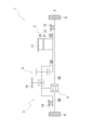
図1は、車両に搭載されるユニットを説明するスケルトン図である。
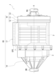
図2は、ユニットの外観図である。
図3は、ユニットの断面模式図である。図3は、インバータケースを取り除いた状態を示している。
図4は、遊星減速ギア周りの拡大図である。
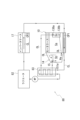
図5は、ユニットにおける冷却水の循環システムを示す図である。
図6は、ギアケースのキャッチタンクを説明する図である。
Embodiments of the present invention will be described below.
FIG. 1 is a skeleton diagram illustrating a unit mounted on a vehicle.
FIG. 2 is an external view of the unit.
FIG. 3 is a schematic cross-sectional view of the unit. FIG. 3 shows the inverter case removed.
FIG. 4 is an enlarged view of the area around the planetary reduction gear.
FIG. 5 is a diagram showing a cooling water circulation system in the unit.
FIG. 6 is a diagram illustrating the catch tank of the gear case.
図1に示すように、ユニット1は、3in1ユニットとして、モータ2と、モータ2が出力した動力を車両の駆動輪K、Kに伝達する動力伝達機構3と、モータ2の電力変換装置であるインバータ7(図2参照)を有する。
As shown in FIG. 1, the
実施の形態では、図1に示すように、ユニット1は、動力伝達機構3として、遊星減速ギア4(減速歯車機構、遊星歯車機構)、差動機構5(差動歯車機構)および出力軸であるドライブシャフトDA、DBを有する。
ユニット1では、モータ2の回転軸X回りの出力回転の伝達経路に沿って、遊星減速ギア4と、差動機構5と、ドライブシャフトDA、DBと、が設けられている。ドライブシャフトDA、DBの軸線は、モータ2の回転軸Xと同軸であり、差動機構5はモータ2と同軸である。
In the embodiment, as shown in FIG. 1, the
In the
ユニット1では、モータ2の出力回転が、遊星減速ギア4で減速されて差動機構5に入力された後、ドライブシャフトDA、DBを介して、ユニット1が搭載された車両の左右の駆動輪K、Kに伝達される。
ここで、遊星減速ギア4は、モータ2の下流に接続されている。差動機構5は、遊星減速ギア4を介してモータ2の下流に接続されている。ドライブシャフトDA、DBは、差動機構5の下流に接続されている。
In the
Here, the
図2に示すように、ユニット1は、3in1タイプのハウジングとして、モータ2、動力伝達機構3およびインバータ7を収容するハウジングHSを有する。ハウジングHSは、1つ以上のケースから構成される。ハウジングHSは、例えば、モータ2を収容するモータケース10と、動力伝達機構3を収容するギアケース14と、インバータ7を収容するインバータケース17と、を有する。回転軸X方向におけるモータケース10の一端側に、ギアケース14が接合されている。ユニット1を車両に搭載した状態における、モータケース10の重力方向上方にインバータケース17が接合されている。
As shown in FIG. 2, the
インバータ7は、平滑コンデンサ、パワー半導体素子、ドライバ基板等を備えた電子部品である。インバータ7は、不図示の配線によってモータケース10内のモータ2と電気的に接続されている。
インバータケース17内には、インバータ7を冷却する冷却水CL(図5参照)が通流する冷却路CP2が形成されている。
The
A cooling path CP2 is formed in the
モータ2は、軸方向視において、差動機構5(差動歯車機構)とオーバーラップする部分を有する(図3参照)。ここで、「軸方向視において」とは、回転軸X方向から視て、という意味である。なお、「径方向視において」とは、回転軸X方向の径方向から視て、という意味である。
軸方向視において、モータ2は遊星減速ギア4(減速歯車機構)にオーバーラップする部分を有する。
軸方向視において、遊星減速ギア4(減速歯車機構)は差動機構5(差動歯車機構)にオーバーラップする部分を有する。
軸方向視において、遊星減速ギア4(減速歯車機構)はモータ2にオーバーラップする部分を有する。
軸方向視において、差動機構5(差動歯車機構)は遊星減速ギア4(減速歯車機構)にオーバーラップする部分を有する。
軸方向視において、差動機構5(差動歯車機構)はモータ2にオーバーラップする部分を有する。
軸方向視において、モータ2は差動機構5(差動歯車機構)とオーバーラップする部分を有する。
The
When viewed in the axial direction, the
When viewed in the axial direction, the planetary reduction gear 4 (reduction gear mechanism) has a portion that overlaps the differential mechanism 5 (differential gear mechanism).
When viewed in the axial direction, the planetary reduction gear 4 (reduction gear mechanism) has a portion that overlaps the
When viewed in the axial direction, the differential mechanism 5 (differential gear mechanism) has a portion that overlaps with the planetary reduction gear 4 (reduction gear mechanism).
The differential mechanism 5 (differential gear mechanism) has a portion that overlaps the
When viewed in the axial direction, the
図3に示すように、モータケース10は、第1ケース部材11と、第1ケース部材11に外挿される第2ケース部材12と、第1ケース部材11の一端に接合されるカバー部材13を有する。第1ケース部材11は、円筒状の支持壁部111と、支持壁部111の一端111aに設けられたフランジ状の接合部112と、を有している。
支持壁部111はモータ2の回転軸Xに沿わせた向きで設けられている。支持壁部111の内側には、モータ2が収容される。
As shown in FIG. 3, the
The
第2ケース部材12は、円筒状の周壁部121と、周壁部121の一端121aに設けられたフランジ状の接合部122と、周壁部121の他端121bに設けられたフランジ状の接合部123と、を有している。
第2ケース部材12の周壁部121は、第1ケース部材11の支持壁部111に外挿可能な内径で形成されている。
第1ケース部材11と第2ケース部材12は、第1ケース部材11の支持壁部111に、第2ケース部材12の周壁部121を外挿して互いに組み付けられている。
The
The
The
周壁部121の一端121a側の接合部122は、回転軸X方向から、第1ケース部材11の接合部112に当接している。これら接合部122、112は、ボルト(図示せず)で互いに連結されている。
The
図3に示すように、第1ケース部材11の支持壁部111に、第2ケース部材12の周壁部121が外挿される。モータケース10の下部の、周壁部121と支持壁部111の間にはクリアランスが設けられている。このクリアランスが、クーラントである冷却水CL(図5参照)が通流する冷却路CP1を形成する。冷却路CP1は、回転軸X方向に沿って延びる。
As shown in FIG. 3 , the
第1ケース部材11の支持壁部111の外周では、冷却路CP1が設けられた領域の両側に、リング溝111c、111cが形成されている。リング溝111c、111cには、シールリング113、113が外嵌して取り付けられている。
これらシールリング113は、支持壁部111に外挿された周壁部121の内周に圧接して、支持壁部111の外周と、周壁部121の内周との間の隙間を封止する。
On the outer periphery of the
These seal rings 113 are in pressure contact with the inner periphery of the
第2ケース部材12の他端121bには、内径側に延びる壁部120(カバー)が設けられている。壁部120は、回転軸Xに直交する向きで設けられている。壁部120の回転軸Xと交差する領域に、ドライブシャフトDAが挿通する開口120aが開口している。
The
壁部120の、モータ2側(図中、右側)の面に、開口120aを囲み、モータ2側に延びる筒状のモータ支持部125が設けられている。
モータ支持部125は、後記するコイルエンド253bの内側に挿入されている。モータ支持部125は、ロータコア21の端部21bに回転軸X方向の隙間をあけて対向している。モータ支持部125の内周には、ベアリングB1が支持されている。モータシャフト20の外周が、ベアリングB1を介してモータ支持部125で支持されている。
A cylindrical
The
壁部120の、差動機構5側(図中、左側)の面に、差動機構5側に延びる筒壁部126が設けられている。筒壁部126は、開口120aを囲む筒状であり、筒壁部126の内周には、ベアリングB2が支持されている。ベアリングB2は、後記するデフケース50の筒壁部61を支持する。
A
カバー部材13は、回転軸Xに直交する壁部130と、接合部132とを有する。
第1ケース部材11から見てカバー部材13は、差動機構5とは反対側(図中、右側)に位置している。カバー部材13の接合部132は、第1ケース部材11の接合部112に回転軸X方向から接合されている。カバー部材13と第1ケース部材11は、ボルト(図示せず)で互いに連結されている。この状態において第1ケース部材11は、支持壁部111の接合部122側(図中、右側)の開口が、カバー部材13で塞がれている。
The
When viewed from the
カバー部材13では、壁部130の中央部に、ドライブシャフトDAの挿通孔130aが設けられている。
挿通孔130aの内周には、リップシールRSが設けられている。リップシールRSは、図示しないリップ部をドライブシャフトDAの外周に弾発的に接触させている。挿通孔130aの内周と、ドライブシャフトDAの外周との隙間が、リップシールRSにより封止されている。
壁部130における第1ケース部材11側(図中、左側)の面には、挿通孔130aを囲む周壁部131が設けられている。周壁部131の内周には、ドライブシャフトDAがベアリングB4を介して支持されている。
In the
A lip seal RS is provided on the inner periphery of the
A
接合部132の内径側には、モータ支持部135および接続壁136が設けられている。モータ支持部135は、周壁部131から見てモータ2側(図中、左側)に設けられている。モータ支持部135は、回転軸Xを間隔を空けて囲む筒状を成している。
モータ支持部135の外周には、円筒状の接続壁136が接続されている。接続壁136は、壁部130側(図中、右側)の周壁部131よりも大きい外径で形成されている。接続壁136は、回転軸Xに沿う向きで設けられており、モータ2から離れる方向に延びている。接続壁136は、モータ支持部135と接合部132とを接続している。
A
A
モータ支持部135の内側を、モータシャフト20の一端20a側が、モータ2側から周壁部131側に貫通している。
モータ支持部135の内周には、ベアリングB1が支持されている。モータシャフト20の外周が、ベアリングB1を介してモータ支持部135で支持されている。
ベアリングB1と隣り合う位置には、リップシールRSが設けられている。
One
A bearing B1 is supported on the inner periphery of the
A lip seal RS is provided at a position adjacent to the bearing B1.
接続壁136の内周に、油孔136a、136bが開口している。接続壁136で囲まれた空間(内部空間Sc)に、油孔136aからオイルOLが流入する。内部空間Scに流入したオイルOLは、油孔136bから排出される。リップシールRSは、接続壁136内のオイルOLのモータ2側への流入を阻止するために設けられている。
ギアケース14は、周壁部141と、周壁部141におけるモータケース10側の端部に設けられたフランジ状の接合部142と、を有している。周壁部141における接合部142と対向側(図中、左側)の端部には、後記するベアリングB2の支持部145が設けられている。周壁部141は、接合部142に接続する筒壁部141aと、支持部145に接続する傾斜部141c(傾斜面)と、これら筒壁部141aと傾斜部141cとを接続する接続壁部141bとを有する。筒壁部141aと接続壁部141bは、接合部142から段階的に縮径して傾斜部141cに接続する。傾斜部141cは、接続壁部141bから支持部145に向かって内径側に傾斜する。周壁部141の内側に、動力伝達機構3である遊星減速ギア4と差動機構5が収容される。
The
ギアケース14は、モータケース10から見て差動機構5側(図中、左側)に位置している。ギアケース14の接合部142は、モータケース10の第2ケース部材12の接合部123に、回転軸X方向から接合されている。ギアケース14と第2ケース部材12は、ボルト(図示せず)で互いに連結されている。
The
接合されたモータケース10およびギアケース14の内部に形成される空間は、第2ケース部材12の壁部120(カバー)によって、2つに区画される。壁部120のモータケース10側がモータ2を収容するモータ室Saであり、ギアケース14側が動力伝達機構3を収容するギア室Sbである。カバーである壁部120は、ハウジングHSの内部において、モータ2と差動機構5に挟まれる。
The space formed inside the joined
カバーは、ハウジングHS内に収容された部分を有するものであれば良く、壁部120のように、全体がハウジングHSに収容されていても良い。また、カバーは、たとえば、第2ケース部材12とは別体としても良い。この場合、カバーは、モータケース10とギアケース14で挟んで固定しても良い。なお、カバーの一部がハウジングHS外に露出しても良い。
The cover may have a portion accommodated within the housing HS, or may be entirely accommodated within the housing HS, like the
モータ2は、円筒状のモータシャフト20と、モータシャフト20に外挿された円筒状のロータコア21と、ロータコア21の外周を間隔を空けて囲むステータコア25とを、有する。
The
モータシャフト20では、ロータコア21の両側に、ベアリングB1、B1が外挿されて固定されている。
ロータコア21から見てモータシャフト20の一端20a側(図中、右側)に位置するベアリングB1は、カバー部材13のモータ支持部135の内周に支持されている。他端20b側(図中、左側)に位置するベアリングB1は、第2ケース部材12の円筒状のモータ支持部125の内周に支持されている。
In the
A bearing B1 located on the one
モータ支持部135、125は、後記するコイルエンド253a、253bの内径側で、ロータコア21の一方の端部21aと他方の端部21bに、回転軸X方向の隙間をあけて対向して配置されている。
The
ロータコア21は、複数の珪素鋼板を積層して形成したものである。珪素鋼板の各々は、モータシャフト20との相対回転が規制された状態で、モータシャフト20に外挿されている。
モータシャフト20の回転軸X方向から見て、珪素鋼板はリング状を成している。珪素鋼板の外周側では、図示しないN極とS極の磁石が、回転軸X周りの周方向に交互に設けられている。
The
When viewed from the direction of the rotation axis X of the
ロータコア21の外周を囲むステータコア25は、複数の電磁鋼板を積層して形成したものである。ステータコア25は、第1ケース部材11の円筒状の支持壁部111の内周に固定されている。
電磁鋼板の各々は、支持壁部111の内周に固定されたリング状のヨーク部251と、ヨーク部251の内周からロータコア21側に突出するティース部252と、を有している。
The
Each of the electromagnetic steel plates has a ring-shaped
本実施形態では、巻線253を、複数のティース部252に跨がって分布巻きした構成のステータコア25を採用している。ステータコア25は、回転軸X方向に突出するコイルエンド253a、253bの分だけ、ロータコア21よりも回転軸X方向の長さが長くなっている。
In this embodiment, the
なお、ロータコア21側に突出する複数のティース部252の各々に、巻線を集中巻きした構成のステータコアを採用しても良い。
Note that a stator core having a configuration in which windings are concentratedly wound on each of the plurality of
第2ケース部材12の壁部120(モータ支持部125)には、開口120aが設けられている。モータシャフト20の他端20b側は、開口120aを差動機構5側(図中、左側)に貫通して、ギアケース14内に位置している。
モータシャフト20の他端20bは、ギアケース14の内側で、後記するサイドギア54Aに、回転軸X方向の隙間をあけて対向している。
The wall portion 120 (motor support portion 125) of the
The
モータシャフト20と壁部120の開口120aの間にはリップシールRSが挿入されている。
ギアケース14の内径側には、遊星減速ギア4と差動機構5を潤滑するためのオイルOLが封入されている。
リップシールRSは、ギアケース14内のオイルOLがモータケース10内に流入することを阻止するために設けられている。
A lip seal RS is inserted between the
Oil OL for lubricating the
The lip seal RS is provided to prevent oil OL in the
図4に示すように、モータシャフト20の、ギアケース14内に位置する領域に遊星減速ギア4のサンギア41がスプライン嵌合している。
As shown in FIG. 4 , a
サンギア41の外周には歯部41aが形成されており、歯部41aには段付きピニオンギア43の大径歯車部431が噛合している。
A
段付きピニオンギア43は、サンギア41に噛合する大径歯車部431(ラージピニオン)と、大径歯車部431よりも小径の小径歯車部432(スモールピニオン)とを有している。
大径歯車部431と小径歯車部432は、回転軸Xに平行な軸線X1方向に並んで配置された、一体のギア部品である。
The stepped
The large-
小径歯車部432の外周は、リングギア42の内周に噛合している。リングギア42は、回転軸Xを間隔を空けて囲むリング状を成している。リングギア42の外周には、係合歯が設けられ、係合歯が接続壁部141bの内周に設けられた歯部146aにスプライン嵌合している。リングギア42は、回転軸X回りの回転が規制されている。
The outer periphery of the small
大径歯車部431および小径歯車部432の内径側をピニオン軸44が貫通している。段付きピニオンギア43は、ピニオン軸44の外周にニードルベアリングNB、NBを介して回転可能に支持されている。
The
図3に示すように、差動機構5は、入力要素であるデフケース50(デファレンシャルケース)と、出力要素であるドライブシャフトDA、DB(出力軸)、差動要素である差動歯車セットを有する。詳細な説明は省略するが、デフケース50は、回転軸方向に組み付けられた2つのケース部材から構成しても良い。
As shown in FIG. 3, the
デフケース50は、遊星減速ギア4の段付きピニオンギア43を支持するキャリアとしても機能する。段付きピニオンギア43は、ピニオン軸44を介して、デフケース50に回転可能に支持されている。図6に示すように、3つの段付きピニオンギア43は、回転軸X周りの周方向に間隔を空けて配置されている。
The
図3に示すように、デフケース50内には、差動歯車セットとして、傘歯車式のデファレンシャルギアであるピニオンメートギア52と、サイドギア54A、54Bが設けられている。ピニオンメートギア52は、ピニオンメートシャフト51に支持されている。
ピニオンメートシャフト51は、回転軸X上に配置された中心部材510と、中心部材510の外径側に連結されたシャフト部材511を有する。図示は省略するが、複数のシャフト部材511が回転軸X周りの周方向に等間隔で設けられている。シャフト部材511は、デフケース50の径方向に延びる支持孔69に挿通され、支持されている。
As shown in FIG. 3, inside the
The
ピニオンメートギア52は、シャフト部材511の各々に1つずつ外挿され、回転可能に支持されている。
One
デフケース50では、回転軸X方向における中心部材510の一方側にサイドギア54Aが位置し、他方側にサイドギア54Bが位置する。サイドギア54A、54Bは、それぞれデフケース50に回転可能に支持される。
サイドギア54Aは、回転軸X方向における一方側から、ピニオンメートギア52に噛合している。サイドギア54Bは、回転軸X方向における他方側から、ピニオンメートギア52に噛合している。
In the
The
デフケース50の一端側(図中、右側)の中央部には、開口60と、開口60を囲み、モータケース10側に延びる筒壁部61が設けられている。筒壁部61の外周は、ベアリングB2を介して、第2ケース部材12の壁部120に支持されている。
An opening 60 and a
デフケース50の内部には、開口60を挿通したドライブシャフトDAが、回転軸X方向から挿入されている。ドライブシャフトDAは、カバー部材13の壁部130の挿通孔130aを貫通し、モータ2のモータシャフト20と、遊星減速ギア4のサンギア41の内径側を回転軸X方向に横切って設けられている。
A drive shaft DA inserted through an opening 60 is inserted into the
図3に示すように、デフケース50の他端側(図中、左側)の中央部には、貫通孔65と、貫通孔65を囲む筒壁部66が形成されている。筒壁部66に、ベアリングB2が外挿されている。筒壁部66に外挿されたベアリングB2は、ギアケース14の支持部145で保持されている。デフケース50の筒壁部66は、ベアリングB2を介して、ギアケース14で回転可能に支持されている。
As shown in FIG. 3, a through
支持部145には、ギアケース14の開口部145aを貫通したドライブシャフトDBが、回転軸X方向から挿入されている。ドライブシャフトDBは、支持部145で回転可能に支持されている。筒壁部66は、ドライブシャフトDBの外周を支持する軸支持部として機能する。
開口部145aの内周には、リップシールRSが固定されている。リップシールRSの図示しないリップ部が、ドライブシャフトDBに外挿されたサイドギア54Bの筒壁部540の外周に弾発的に接触している。
これにより、サイドギア54Bの筒壁部540の外周と開口部145aの内周との隙間が封止されている。
A drive shaft DB passing through an
A lip seal RS is fixed to the inner periphery of the
Thereby, a gap between the outer periphery of the
デフケース50の内部では、ドライブシャフトDA、DBの先端部が、回転軸X方向に間隔を空けて対向している。
ドライブシャフトDA、DBの先端部の外周に、デフケース50に支持されたサイドギア54A、54Bがスプライン嵌合している。サイドギア54A、54BとドライブシャフトDA、DBとが、回転軸X周りに一体回転可能に連結されている。
Inside the
Side gears 54A, 54B supported by the
この状態においてサイドギア54A、54Bは、回転軸X方向で間隔をあけて、対向配置されている。サイドギア54A、54Bの間に、ピニオンメートシャフト51の中心部材510が位置している。
ピニオンメートギア52は、回転軸X方向の一方側に位置するサイドギア54Aおよび他方側に位置するサイドギア54Bに、互いの歯部を噛合させた状態で組み付けられている。
In this state, the side gears 54A and 54B are disposed facing each other with an interval in the direction of the rotation axis X. A
The
図4に示すように、デフケース50の一端側(図中、右側)の、開口60の外径側に、ピニオン軸44の一端44a側の支持孔62が形成されている。デフケース50の他端側(図中、左側)には、ピニオン軸44の他端44b側の支持孔68が形成されている。
As shown in FIG. 4, a support hole 62 on the one
支持孔62、68は、回転軸X方向にオーバーラップする位置に形成される。支持孔62、68は、それぞれ、段付きピニオンギア43を配置する位置に合わせて、回転軸X周りの周方向に間隔を空けて形成される。ピニオン軸44の一端44aが支持孔62に挿入され、他端44bが支持孔68に挿入される。ピニオン軸44は、他端44bが支持孔68に圧入されることで、ピニオン軸44はデフケース50に対して相対回転不能に固定されている。ピニオン軸44に外挿された段付きピニオンギア43は、回転軸Xに平行な軸線X1回りに回転可能に支持されている。
The support holes 62 and 68 are formed at positions that overlap in the rotation axis X direction. The support holes 62 and 68 are formed at intervals in the circumferential direction around the rotation axis X, respectively, in accordance with the position where the stepped
図示は省略するが、ギアケース14の内部には、潤滑用のオイルOLが貯留されている。デフケース50が回転軸X回りに回転すると、オイルOLがデフケース50によって掻き上げられる。
詳細な説明は省略するが、デフケース50、ピニオン軸44等には、デフケース50に掻き上げられたオイルOLを導入するための油路、油孔等が設けられている。これによって、ベアリングB2、ニードルベアリングNB等の回転部材にオイルOLが導入されやすくなっている。
Although not shown, lubricating oil OL is stored inside the
Although detailed description will be omitted, the
また、図6に示すように、ギアケース14内の、デフケース50の上部に、キャッチタンク15が設けられている。キャッチタンク15は、回転軸Xと直交する鉛直線VLを挟んだ一方側(図中、左側)に位置している。キャッチタンク15と、デフケース50の収容部140とは、連通口147を介して連通している。デフケース50によって掻き上げられて飛散したオイルOLの一部は、連通口147からキャッチタンク15内に流入して捕集される。
Further, as shown in FIG. 6, a
ユニット1を搭載した車両の前進走行時に、モータケース10側から見てデフケース50は、回転軸X周りの反時計回り方向CCWに回転する。図4に示すように、段付きピニオンギア43の小径歯車部432は、ギアケース14の内周に固定されたリングギア42に噛合している。そのため、段付きピニオンギア43の大径歯車部431は、図6に示すように、軸線X1回りを時計回り方向に自転しながら、回転軸X周りの反時計回り方向CCWに公転する。
When the vehicle in which the
キャッチタンク15は、鉛直線VLを挟んだ左側、すなわちデフケース50の回転方向における下流側に位置している。これにより、回転軸X回りに回転するデフケース50で掻き上げられたオイルOLの多くが、キャッチタンク15内に流入できるようになっている。
図3に示すように、キャッチタンク15は、油路151aを介して、リップシールRSとベアリングB2との間の空間Rxに接続している。また、キャッチタンク15は、不図示の油路、配管等を介して、オイルクーラ83(図5参照)に接続している。オイルクーラ83は、不図示の配管、油路等を介して、接続壁136に形成された油孔136a(図3参照)に接続している。
The
As shown in FIG. 3, the
ギアケース14の周壁部141には、油孔Haが形成されている。油孔Haは、不図示の配管を介して、内部空間Scに形成された油孔136bと接続している。油孔136bを介して内部空間Scから排出されたオイルOLは、油孔Haから再びギア室Sb内部に供給される。
An oil hole Ha is formed in the
図5に示すように、ユニット1には、冷却水CLの循環システム80が設けられている。循環システム80は、前記したモータケース10の冷却路CP1とインバータケース17の冷却路CP2との間で、冷却水CLを循環させる。循環システム80は、さらに、冷却路CP1と冷却路CP2の間に、オイルクーラ83、ウォーターポンプWPおよびラジエータ82を備えており、これらは冷却水CLが通流する配管等で接続されている。
As shown in FIG. 5, the
ウォーターポンプWPは、冷却水CLを循環システム80内において圧送する。
ラジエータ82は、冷却水CLの熱を放熱して冷却する装置である。
Water pump WP pumps cooling water CL within
The
オイルクーラ83は、冷却水CLと、オイルOLとの熱交換を行う熱交換器である。オイルクーラ83には、ギアケース14のギア室Sb内に設けられたキャッチタンク15で捕集されたオイルOLが導入される。オイルOLは、冷却水CLとの熱交換により冷却される。冷却されたオイルOLは、モータケース10の油孔136aから内部空間Scに供給される。なお、オイルクーラ83に供給するオイルOLは、キャッチタンク15で捕集されたオイルOLに限定されず、ハウジングHSに適宜設けた別の油路から供給しても良い。また、オイルクーラ83から排出されたオイルOLを、内部空間Scとは別の箇所に供給しても良い。
The
冷却水CLは、インバータケース17内の冷却路CP2およびモータケース10内の冷却路CP1を通流した後に、オイルクーラ83に供給される。冷却水CLは、オイルクーラ83においてオイルOLとの熱交換が行われた後に、ラジエータ82で冷却され、再びインバータケース17の冷却路CP2に供給される。
Cooling water CL is supplied to oil cooler 83 after passing through cooling path CP2 in
図7は、ハウジングHSに取り付けられたオイルクーラ83を示す図である。図7は、図2の紙面奥側から見た状態を示す模式図である。
図8は、図7のA-A断面の模式図である。図8では、モータケース10およびインバータケース17の内部は簡略化して示しており、モータ2およびインバータ7の外周を破線で示している。また、オイルクーラ83の本体部830の内部の図示は省略している。
図9は、オイルクーラ83の構成を説明する図である。
図10は、図7のオイルクーラ83周りの拡大図である。図10では、凹部90をわかりやすくするために、オイルクーラ83を破線で示している。
図11は、オイルクーラ83の組付けを説明する図である。
FIG. 7 is a diagram showing the
FIG. 8 is a schematic diagram of the AA cross section in FIG. 7. In FIG. 8, the insides of
FIG. 9 is a diagram illustrating the configuration of the
FIG. 10 is an enlarged view of the
FIG. 11 is a diagram illustrating the assembly of the
図7に示すように、オイルクーラ83(熱交換器)は、ハウジングHSのモータケース10の外壁面に配置されている。以降の説明において、ハウジングHSの回転軸Xに沿った方向(図7の紙面左右方向)を、長手方向という。長手方向および鉛直線VLに直交する方向(図8の紙面左右方向)を幅方向という。
As shown in FIG. 7, the oil cooler 83 (heat exchanger) is arranged on the outer wall surface of the
モータ2は円柱状であり、図8に示すように、回転軸X方向から視て円形を成す。図8において、モータ2の軸心である回転軸Xを通り、かつ鉛直線VLに直交する水平面Sを示している。モータ2を収容するモータケース10は、水平面Sより上方の部分である上方部101と、下方の部分である下方部105を有する。上方部101はモータ2の水平面Sより上方の外周を囲み、下方部105はモータ2の水平面Sより下方の外周を囲んでいる。
The
モータケース10の下方部105は、回転軸X方向から視て、円形のモータ2の外周に沿った円弧を成している。下方部105には、前記した冷却水CLが通流する冷却路CP1が形成されている。
The
モータケース10の上方部101は、回転軸X方向から視て矩形である。図7に示すように、上方部101の上端面102には、直方体形状のインバータケース17の下端面171が接合される。すなわち、モータケース10の上方部101は、インバータケース17との連結部として機能する。
The
図8に示すように、モータケース10の上方部101の、幅方向における一方の端部101a側(図中、右側)には、インバータケース17に設けられた冷却路CP2と、モータケース10の下方部105に設けられた冷却路CP1を連通させる連通路WDが設けられている。
As shown in FIG. 8, a cooling path CP2 provided in the
上方部101の幅方向における他方の端部101b側(図中、左側)には、オイルクーラ83の収容部である凹部90が設けられている。
A
図9に示すように、オイルクーラ83は、直方体形状の本体部830を有する。本体部830は、間隔を空けて平行に設けられた上面部831および底面部832を有する。図9および図11に示すように、直方体形状の本体部830において、上面部831および底面部832は4つの側面部833a~833dに接続されている。
As shown in FIG. 9, the
図9に示すように、側面部833aは、本体部830の長手方向における一端側(図中、右側)に位置し、側面部833bは他端側(図中、左側)に位置する。図11に示すように、側面部833cは、本体部830の幅方向における一端側(図中、右側)に位置し、側面部833dは他端側(図中、左側)に位置する。
As shown in FIG. 9, the
図示は省略するが、上面部831、底面部832および側面部833a~833dに囲まれた本体部830の内部空間に、オイルOLの流路と冷却水CLの流路が設けられている。本体部830においてオイルOLと冷却水CLがそれぞれの流路を通流することで、熱交換が行われる。
Although not shown, an oil OL flow path and a cooling water CL flow path are provided in the internal space of the
側面部833dには、本体部830にオイルOLを導入するパイプPaと、本体部830からオイルOLを排出するパイプPbが設けられている。側面部833dには、また、本体部830に冷却水CLを導入するパイプPcと、本体部830から冷却水CLを排出するパイプPdが設けられている。
A pipe Pa for introducing oil OL into the
パイプPa、Pb、Pc、Pdは、側面部833dから突出して設けられている。なお、パイプPa、Pb、Pc、Pdを設ける位置は図示の例に限定されず、本体部830の内部に形成する流路の配置等に応じて、側面部833dに適宜配置することができる。
The pipes Pa, Pb, Pc, and Pd are provided to protrude from the
側面部833dの上端と下端には、板状のタブ835が設けられている。タブ835は、側面部833dに接合する接合部835aと、接合部835aに接続する先端部835bとを備える。先端部835bは、接合部835aから鉛直線方向に延び、側面部833dの外方に突出する。
側面部833dの上端に設けられたタブ835は、側面部833dの鉛直線VL方向上方に突出する。側面部833dの下端部に設けられたタブ835は、側面部833dの鉛直線VL方向下方に突出する。タブ835の先端部835bには、ボルトの挿通孔835cが形成されている。タブ835は、側面部833dの上端および下端の、長手方向における両端側に設けられている。側面部833dには、4つのタブ835が設けられている。
Plate-shaped
A
図8に示すように、モータケース10の上方部101に設けられた凹部90は、オイルクーラ83の本体部830を収容する。凹部90は、直方体形状の本体部830に整合した形状を有する。凹部90は、上方部101の外壁を、端部101b側(図中、左側)から端部101a側(図中、右側)に向けて、幅方向に切り欠いて設けられる。鉛直線VL方向において、凹部90は、上方部101の水平面S近傍の位置から、インバータケース17の下端面171に接合された上端面102にまで至る。そのため、図10に示すように、凹部90の構成する面の中で、上壁面91は、インバータケース17の下端面171によって構成される。凹部90の底壁面92は、上壁面91に対して間隔を空けて平行に設けられている。
As shown in FIG. 8, the
図10および図11に示すように、凹部90は、上壁面91および底壁面92を接続する3つの側壁面94a、94b、94cを有する。図10に示すように、側壁面94aは凹部90の長手方向における一端側に位置し、側壁面94bは他端側に位置する。図11に示すように、側壁面94cは、凹部90の幅方向における一端側(図中、右側)に位置する。凹部90の長手方向における一端側(図中、左側)には、開口部93が設けられている。オイルクーラ83の本体部830は、開口部93から凹部90の内部に収容される。
As shown in FIGS. 10 and 11, the
図11に示すように、凹部90に収容されたオイルクーラ83の本体部830は、その長手方向が、モータケース10およびインバータケース17の長手方向に沿って延在するように配置される。本体部830の底面部832が、凹部90の底壁面92に対向する。すなわち、オイルクーラ83は、モータケース10とインバータケース17とに挟まれた形で配置される。
As shown in FIG. 11, the
図11に示すように、本体部830の側面部833cは、凹部90の側壁面94cに対向する。本体部830の側面部833dは、凹部90の開口部93に位置する。すなわち、本体部830は、側面部833dがモータケース10の外部に面した状態で凹部90に収容される。
As shown in FIG. 11, a
図7に示すように、側面部833dに突出して設けられたパイプPa、Pb、Pc、Pdおよびタブ835は、開口部93からモータケース10の外部に張り出す。
図11に示すように、本体部830の上端部に設けられたタブ835の先端部835bは、開口部93の鉛直線VL方向上方に延び、インバータケース17の外壁に対向する。図11に示すように、先端部835bの挿通孔835cを挿通させたボルトBを、インバータケース17の外壁に螺入させることで、タブ835はインバータケース17に固定される。
As shown in FIG. 7, the pipes Pa, Pb, Pc, Pd and
As shown in FIG. 11, a
本体部830の下端部に設けられたタブ835の先端部835bは、開口部93の鉛直線VL方向下方に延び、モータケース10の外壁に対向する。先端部835bの挿通孔835cを挿通させたボルトBを、モータケース10の外壁に螺入させることで、タブ835はモータケース10に固定される。
A
オイルクーラ83の本体部830は、タブ835を介して、上側がインバータケース17に固定され、下側がモータケース10に固定される。タブ835は、オイルクーラ83をボルトB(締結具)でインバータケース17およびモータケース10に取り付ける際の、座面として機能する。
The
パイプPaは、不図示の配管、油路等を介して、ギアケース14に設けられたキャッチタンク15(図3参照)に接続する。パイプPbは、不図示の配管、油路等を介して、接続壁136の油孔136a(図3参照)に接続する。パイプPcは、不図示の配管、油路等を介して、モータケース10内の冷却路CP1に接続する。パイプPdは、不図示の配管等を介して、ラジエータ82(図5参照)に接続する。
The pipe Pa is connected to a catch tank 15 (see FIG. 3) provided in the
かかる構成のユニット1の作用を説明する。
図1に示すように、ユニット1では、モータ2の出力回転の伝達経路に沿って、遊星減速ギア4と、差動機構5と、ドライブシャフトDA、DBと、が設けられている。
The operation of the
As shown in FIG. 1, in the
図3に示すように、モータ2が駆動されて、ロータコア21が回転軸X回りに回転すると、ロータコア21と一体に回転するモータシャフト20を介して、遊星減速ギア4のサンギア41に回転が入力される。
As shown in FIG. 3, when the
遊星減速ギア4では、サンギア41が、モータ2の出力回転の入力部となっており、段付きピニオンギア43を支持するデフケース50が、入力された回転の出力部となっている。
In the
図4に示すように、サンギア41が入力された回転で回転軸X回りに回転すると、段付きピニオンギア43(大径歯車部431、小径歯車部432)が、サンギア41側から入力される回転で、軸線X1回りに回転する。
ここで、段付きピニオンギア43の小径歯車部432は、ギアケース14の内周に固定されたリングギア42に噛合している。そのため、段付きピニオンギア43は、軸線X1回りに自転しながら、回転軸X周りに公転する。
As shown in FIG. 4, when the
Here, the small
ここで、段付きピニオンギア43では、小径歯車部432の外径が大径歯車部431の外径よりも小さくなっている。
これにより、段付きピニオンギア43を支持するデフケース50が、モータ2側から入力された回転よりも低い回転速度で回転軸X回りに回転する。
そのため、遊星減速ギア4のサンギア41に入力された回転は、段付きピニオンギア43により、大きく減速されたのちに、デフケース50(差動機構5)に出力される。
Here, in the stepped
As a result, the
Therefore, the rotation input to the
図3に示すように、デフケース50が入力された回転で回転軸X回りに回転することにより、デフケース50内で、ピニオンメートギア52と噛合するドライブシャフトDA、DBが回転軸X回りに回転する。これによりユニット1が搭載された車両の左右の駆動輪(図示せず)が、伝達された回転駆動力で回転する。
As shown in FIG. 3, when the
ギア室Sbの内部には、潤滑用のオイルOLが貯留される。ギア室Sbにおいては、モータ2の出力回転の伝達時に、オイルOLが、回転軸X回りに回転するデフケース50により掻き上げられる。
図3および図4に示すように、掻き上げられたオイルOLにより、サンギア41と大径歯車部431との噛合部と、小径歯車部432とリングギア42との噛合部と、ピニオンメートギア52とサイドギア54A、54Bとの噛合部とが潤滑される。
Lubricating oil OL is stored inside the gear chamber Sb. In the gear chamber Sb, when the output rotation of the
As shown in FIGS. 3 and 4, the scraped up oil OL damages the meshing part between the
図6に示すように、デフケース50は、回転軸X周りの反時計回り方向CCWに回転する。
ギアケース14の上部には、キャッチタンク15が設けられている。キャッチタンク15は、デフケース50の回転方向における下流側に位置しており、デフケース50で掻き上げられたオイルOLの一部が、キャッチタンク15内に流入する。
As shown in FIG. 6, the
A
図3に示すように、キャッチタンク15に流入したオイルOLの一部は、油路151aを介して、リップシールRSとベアリングB2との間の空間Rxに供給され、ベアリングB2を潤滑する。
As shown in FIG. 3, a part of the oil OL that has flowed into the
キャッチタンク15に流入したオイルOLの一部は、不図示の油路、配管等を介してオイルクーラ83のパイプPaから本体部830(図9参照)に導入される。オイルクーラ83の本体部830には、パイプPcを介して、冷却路CP1(図5参照)を通流した後の冷却水CLが導入される。オイルクーラ83の本体部830において、オイルOLと冷却水CLの熱交換が行われることで、オイルOLが冷却される。冷却されたオイルOLは、パイプPbを介して本体部830から排出される。冷却水CLは、パイプPdを介して本体部830から排出され、不図示の配管等を介してラジエータ82(図5参照)に供給される。
A portion of the oil OL that has flowed into the
本体部830から排出されたオイルOLは、不図示の配管等を介して、接続壁136に形成された油孔136aから内部空間Sc(図3参照)に供給される。内部空間Scに供給されたオイルOLは、ベアリングB4を潤滑し、油孔136bから排出される。油孔136bから排出されたオイルOLは、不図示の配管等を介して、油孔Haからギア室Sb内に供給される。
The oil OL discharged from the
前記したように、実施の形態におけるユニット1は、3in1ユニットである。図7に示すように、ハウジングHSにおいて、インバータケース17はモータケース10に接合され、一体に形成されている。インバータケース17は、回転軸Xの径方向視において、モータケース10とオーバーラップしている。
As described above, the
図8に示すように、直方体形状のインバータケース17に接合されるモータケース10の上方部101は、回転軸X方向から視て矩形である。一方、モータケース10に収容されたモータ2は回転軸X方向から視て円形である。そのため、上方部101の外壁とモータ2の外周との間にはクリアランスが生じる。実施の形態では、このクリアランスの部分に、オイルクーラ83を収容する凹部90を設けている。
As shown in FIG. 8, the
凹部90に収容された状態で、インバータケース17は、鉛直線VL方向(重力方向)から視て、オイルクーラ83およびモータケース10とオーバーラップする。凹部90は、モータケース10の外壁を切り欠いて設けられ、モータケース10の外壁と、インバータケース17の下端面171とから構成されるため、オイルクーラ83は、モータケース10とインバータケース17に挟まれて配置される。これにより、オイルクーラ83は、モータケース10およびインバータケース17から大きく突出することなく配置され、ユニット1の寸法の縮小に寄与する。
In the state accommodated in the
オイルクーラ83の収容部である凹部90は、モータケース10の外壁を切り欠いて形成している。本体部830は凹部90内に収容されるが、側面部833dに設けられたタブ835とパイプPa、Pb、Pc、Pdは凹部90の開口部93(図11参照)から外部に突出している。
A
図11に示すように、側面部833dの上端に設けられたタブ835の先端部835bは、側面部833dから鉛直線VL方向上方に突出して、インバータケース17の外壁に幅方向で対向する。側面部833dの下端に設けられたタブ835の先端部835bは、側面部833dから鉛直線VL方向下方に突出して、インバータケース17の外壁に幅方向で対向する。
鉛直線VL方向(重力方向)および回転軸Xに交差する交差方向、すなわち、幅方向から視て、オイルクーラ83は、タブ835の先端部835bにおいて、モータケース10またはインバータケース17とオーバーラップする。
As shown in FIG. 11, the
The
モータケース10またはインバータケース17に対向するタブ835の先端部835bをボルトBの座面とし、ボルトBの挿通孔835cを設けることで、タブ835をモータケース10またはインバータケース17の外壁にボルトBで容易に固定することができる。
The
側面部833dに設けられたパイプPa~Pdが開口部93から突出することで、配管等を取り付けやすくなる。ユニット1の設置作業を容易にすることができる。
The pipes Pa to Pd provided on the
以上の通り、実施の形態にかかるユニット1は、以下の構成を有する。
(1)ユニット1は、
オイルクーラ83(熱交換器)と、
モータ2を収容するモータケース10と、
インバータ7を収容するインバータケース17と、を有する。
所定方向視である鉛直線VL方向視(重力方向視)において、インバータケース17はオイルクーラ83及びモータケース10とオーバーラップする部分を有する。
As mentioned above, the
(1)
Oil cooler 83 (heat exchanger),
a
It has an
このように構成することで、オイルクーラ83を搭載したユニット1において少なくとも一方向における寸法の縮小に寄与する。
具体的には、インバータケース17がモータケース10に接合された3in1ユニットにおいて、モータケース10の上方部101の外壁面を切り欠いて凹部90を設け、オイルクーラ83の本体部830を収容する。これによって、鉛直線VL方向視(重力方向視)においてオイルクーラ83の本体部830は、インバータケース17およびモータケース10とオーバーラップする。オイルクーラ83が、モータケース10およびインバータケース17から大きく突出することなく配置される。これによって、ユニット1の少なくとも回転軸X方向の寸法の縮小に寄与する。
This configuration contributes to reducing the size of the
Specifically, in a 3-in-1 unit in which the
(2)オイルクーラ83は、モータケース10とインバータケース17とに挟まれた部分を有する。
(2)
オイルクーラ83を収容する凹部90は、モータケース10の外壁面を切り欠いて設けられる。凹部90の上壁面91は、インバータケース17の下端面171によって構成される(図10、図11参照)。凹部90の底壁面92および側壁面94a、94b、94cは、モータケース10の外壁面によって構成される。すなわち、オイルクーラ83の本体部830は、モータケース10とインバータケース17とに挟まれて配置される。このように構成することで、オイルクーラ83が、モータケース10およびインバータケース17から大きく突出することなく配置されるため、ユニット1の寸法の縮小に寄与する。
A
(3)所定方向(鉛直線VL方向)と交差する幅方向(交差方向)視において、オイルクーラ83はモータケース10及び/又はインバータケース17とオーバーラップするタブ835を有する。
(3) The
オイルクーラ83にこのようなタブ835を設け、たとえば、タブ835に挿入孔を設けてボルトB等の締結具の座面とすることで、オイルクーラ83をモータケース10およびインバータケース17に容易に固定することができ、オイルクーラ83の組付け性を向上させることができる。
なお、タブ835を締結具の座面とする代わりに、または座面とすると共に、外壁面に締結させるストッパとして構成しても良い。
いずれの場合も、オイルクーラ83はタブ835を介してモータケース10及び/又はインバータケース17に締結されていると言える。
By providing such a
Note that instead of using the
In either case, it can be said that the
(4、5)インバータケース17は、モータケース10と一体形成された部分を有する。
(4, 5) The
いわゆる3in1ユニットにおいては、インバータケース17とモータケース10との連結部が存在する。たとえば、モータケース10の上方部101が、インバータケース17との連結部である。インバータケース17は、モータケース10と一体形成された部分として、連結部を有する。この連結部の一部を除去した空間(凹部90)を利用してオイルクーラ83を配置することで、オイルクーラ83をモータケース10とインバータケース17とに挟まれた構造にしやすくなる。
In the so-called 3-in-1 unit, there is a connecting portion between the
(6)オイルクーラ83の長手方向は、インバータケース17の長手方向に沿って延在する。
これによって、オイルクーラ83の長手方向が、インバータケース17から大きく突出することが低減されるため、ユニット1の寸法の縮小に寄与する。
(6) The longitudinal direction of the
This reduces the possibility that the
オイルクーラ83を、所定方向視においてモータケース10およびインバータケース17にオーバーラップするように配置する態様は、実施の形態の態様に限定されない。以下に、変形例を説明する。
The manner in which
(変形例1)
図12は、変形例1にかかるユニットを説明する図である。
以降の変形例で用いる図は、オイルクーラ83の配置を説明するための模式図である。ハウジングHSは簡略化して、モータケース10およびインバータケース17のみを模式的に示している。オイルクーラ83はハッチングを付して示している。
(Modification 1)
FIG. 12 is a diagram illustrating a unit according to
The figures used in the subsequent modifications are schematic diagrams for explaining the arrangement of the
図12に示すように、変形例1では、オイルクーラ83は、モータケース10内に配置されている。図示は省略するが、モータケース10内にオイルクーラ83を収容する収容室を設けても良い。
As shown in FIG. 12, in the first modification, the
変形例1においても、実施の形態と同様に、オイルクーラ83を、回転軸X方向から視て矩形の上方部101と、円形のモータ2の間に形成されるクリアランスに配置している。このクリアランスを有効に活用するために、オイルクーラ83は、三角柱形状としても良い。ここで、オイルクーラ83の、回転軸X方向から視て円形のモータ2の外周に対向する面は、円弧状としても良い。
In the first modification as well, the
なお、オイルクーラ83は三角柱形状に限られず、たとえば、円柱形状または直方体形状のオイルクーラ83をモータケース10の内部に配置しても良い。また、オイルクーラ83は、上方部101の端部101b側に配置される例のみに限定されない。たとえば、モータケース10内の、モータ2の鉛直線VL方向上方において、端部101a側から端部101b側に延在するように、オイルクーラ83を配置しても良い。
Note that the
変形例1においても、実施の形態と同様に、オイルクーラ83は、所定方向である鉛直線VL方向視(重力方向視)において、モータケース10およびインバータケース17にオーバーラップする。これにより、ユニット1の少なくとも回転軸X方向の寸法の縮小に寄与する。
In
(変形例2)
図13は、変形例2にかかるユニットを説明する図である。
図13に示すように、変形例2では、オイルクーラ83を、モータケース10とインバータケース17の間に配置している。オイルクーラ83は、モータケース10の上端面102と、インバータケース17の下端面171とに接合される。変形例2では、インバータケース17は、オイルクーラ83を介してモータケース10に接続される。
なお、変形例2では、インバータケース17の冷却路CP2(図3参照)と、モータケース10の冷却路CP1(図3参照)を接続するための配管を、別途設けても良い。
(Modification 2)
FIG. 13 is a diagram illustrating a unit according to
As shown in FIG. 13, in the second modification, an
In addition, in the
変形例2においても、実施の形態と同様に、オイルクーラ83は、所定方向である鉛直線VL方向視(重力方向視)において、モータケース10およびインバータケース17にオーバーラップする。また、オイルクーラ83は、モータケース10とインバータケース17に挟み込まれる。これにより、ユニット1の少なくとも回転軸X方向の寸法の縮小に寄与する。
In
なお、モータケース10の上端面102に凹部90を設けて、凹部90内にオイルクーラ83を配置しても良い。
Note that a
(変形例3)
図14は、変形例3にかかるユニットを説明する図である。
図14に示すように、変形例3では、インバータケース17の一部が、長手方向においてモータケース10に対してオフセットして配置されている。オイルクーラ83は、インバータケース17のオフセット部分の鉛直線VL方向下方において、モータケース10に隣接して配置される。すなわち、オイルクーラ83は、インバータケース17に対して鉛直線VL方向視(所定方向視)においてオーバーラップする部分と、モータケース10に対して回転軸X方向視(所定方向視)においてオーバーラップする部分を有する。
(Modification 3)
FIG. 14 is a diagram illustrating a unit according to modification example 3.
As shown in FIG. 14, in the third modification, a part of the
このように、オイルクーラ83を、インバータケース17のモータケース10からオフセットする部分にオーバーラップするように配置することで、オイルクーラ83をインバータケース17から大きく突出することがなく配置することができ、ユニット1の寸法の縮小に寄与する。
In this way, by arranging the
(変形例4)
図15は、変形例4にかかるユニットを説明する図である。図15では、モータケース10は簡略化して直方体として図示している。
図15に示すように、変形例4では、インバータケース17の一部が、幅方向においてモータケース10に対してオフセットして配置されている。オイルクーラ83は、インバータケース17のオフセット部分の鉛直線VL方向下方において、モータケース10に隣接して配置される。すなわち、オイルクーラ83は、インバータケース17に対して鉛直線VL方向視(所定方向視)においてオーバーラップする部分と、モータケース10に対して鉛直線VL方向および回転軸X方向に交差する幅方向視(所定方向視)においてオーバーラップする部分を有する。
(Modification 4)
FIG. 15 is a diagram illustrating a unit according to
As shown in FIG. 15, in the fourth modification, a part of the
このように、オイルクーラ83を、インバータケース17のモータケース10からオフセットする部分にオーバーラップするように配置することで、オイルクーラ83をインバータケース17から大きく突出することがなく配置することができ、ユニット1の寸法の縮小に寄与する。
In this way, by arranging the
(変形例5)
図16は、変形例5にかかるユニットを説明する図である。図15では、モータケース10は簡略化して直方体として図示している。
実施の形態では、モータケース10の幅方向における端部101b(図8参照)に、オイルクーラ83を収容する凹部90を設ける例を説明したが、これに限定されない。図16に示すように、凹部90は、モータケース10の回転軸X方向における端部101cに設けても良い。
(Modification 5)
FIG. 16 is a diagram illustrating a unit according to
In the embodiment, an example has been described in which the
変形例5においても、実施の形態と同様に、オイルクーラ83は、所定方向である鉛直線VL方向視(重力方向視)において、モータケース10およびインバータケース17にオーバーラップする。また、オイルクーラ83は、モータケース10とインバータケース17に挟み込まれる。これにより、ユニット1の少なくとも回転軸X方向の寸法の縮小に寄与する。
In the fifth modification, as in the embodiment, the
さらなる変形例として、たとえば、モータケース10の下方にオイルクーラ83を配置しても良い。また、たとえば、インバータケース17の上方にオイルクーラ83を配置しても良い。この場合も、オイルクーラ83は、所定方向である鉛直線VL方向視(重力方向視)において、モータケース10およびインバータケース17にオーバーラップするため、ユニット1の少なくとも回転軸X方向の寸法の縮小に寄与する。
As a further modification, for example, the
本発明のある態様において、動力伝達機構3は、例えば、歯車機構、環状機構等を有する。
歯車機構は、例えば、減速歯車機構、増速歯車機構、差動歯車機構(差動機構)等を有する。
減速歯車機構及び増速歯車機構は、例えば、遊星歯車機構、平行歯車機構等を有する。
環状機構は、例えば、無端環状部品等を有する。
無端環状部品等は、例えば、チェーンスプロケット、ベルトとプーリ等を有する。
In an embodiment of the present invention, the
The gear mechanism includes, for example, a reduction gear mechanism, a speed increase gear mechanism, a differential gear mechanism (differential mechanism), and the like.
The reduction gear mechanism and the speed increase gear mechanism include, for example, a planetary gear mechanism, a parallel gear mechanism, and the like.
The annular mechanism includes, for example, an endless annular component.
Endless annular parts and the like include, for example, chain sprockets, belts, and pulleys.
差動機構5は、例えば、傘歯車式のデファレンシャルギア、遊星歯車式のデファレンシャルギア等である。
差動機構5は、入力要素であるデファレンシャルケースと、出力要素である2つの出力軸と、差動要素である差動歯車セットと、を有する。
傘歯車式のデファレンシャルギアにおいて、差動歯車セットは傘歯車を有する。
遊星歯車式のデファレンシャルギアにおいて、差動歯車セットは遊星歯車を有する。
The
The
In a bevel gear type differential gear, the differential gear set has a bevel gear.
In a planetary gear type differential gear, the differential gear set has planetary gears.
ユニット1は、デファレンシャルケースと一体回転するギアを有する。
例えば、平行歯車機構のうちのファイナルギア(デフリングギア)は、デファレンシャルケースと一体に回転する。例えば、遊星歯車機構のキャリアとデファレンシャルケースとが接続している場合、ピニオンギアがデファレンシャルケースと一体に回転(公転)する。
The
For example, the final gear (differential ring gear) of the parallel gear mechanism rotates together with the differential case. For example, when the carrier of the planetary gear mechanism and the differential case are connected, the pinion gear rotates (revolutions) together with the differential case.
例えば、モータ2の下流に減速歯車機構が接続されている。減速歯車機構の下流に差動歯車機構が接続されている。即ち、モータ2の下流には、減速歯車機構を介して差動歯車機構が接続されている。なお、減速歯車機構に替えて増速歯車機構としても良い。
シングルピニオン型の遊星歯車機構は、例えば、サンギアを入力要素とし、リングギアを固定要素とし、キャリアを出力要素とすることができる。
ダブルピニオン型の遊星歯車機構は、例えば、サンギアを入力要素とし、リングギアを出力要素とし、キャリアを固定要素とすることができる。
シングルピニオン型又はダブルピニオン型の遊星歯車機構のピニオンギアは、例えば、ステップドピニオンギア、ノンステップドピニオンギア等を用いることができる。
ステップドピニオンギアは、ラージピニオンおよびとスモールピニオンとを有する。例えば、ラージピニオンをサンギアに噛合させると好適である。例えば、スモールピニオンをリングギアに嵌合させると好適である。
ノンステップドピニオンギアは、ステップドピニオンギアではない形式である。
For example, a reduction gear mechanism is connected downstream of the
A single pinion type planetary gear mechanism can, for example, use a sun gear as an input element, a ring gear as a fixed element, and a carrier as an output element.
A double pinion type planetary gear mechanism can have, for example, a sun gear as an input element, a ring gear as an output element, and a carrier as a fixed element.
As the pinion gear of the single pinion type or double pinion type planetary gear mechanism, for example, a stepped pinion gear, a non-stepped pinion gear, etc. can be used.
The stepped pinion gear has a large pinion and a small pinion. For example, it is preferable to mesh the large pinion with the sun gear. For example, it is preferable to fit the small pinion into the ring gear.
A non-stepped pinion gear is a type of gear that is not a stepped pinion gear.
本実施形態では、本発明のある態様におけるユニット1を車両に搭載する例を説明したが、この態様に限定されない。本発明は、車両以外にも適用することができる。また、本実施形態において複数の実施例、変形例が記載されている場合は、これらを任意に組み合わせても良い。
In this embodiment, an example has been described in which the
以上、本発明の実施形態について説明したが、上記実施形態は本発明の適用例の一つを示したものに過ぎず、本発明の技術的範囲を上記実施形態の具体的構成に限定する趣旨ではない。発明の技術的な思想の範囲内で、適宜変更可能である。 Although the embodiments of the present invention have been described above, the above embodiments are merely examples of application of the present invention, and the technical scope of the present invention is limited to the specific configuration of the above embodiments. isn't it. Changes can be made as appropriate within the scope of the technical idea of the invention.
1 :ユニット
2 :モータ
7 :インバータ
10 :モータケース
17 :インバータケース
83 :オイルクーラ(熱交換器)
835 :タブ
VL :鉛直線
1: Unit 2: Motor 7: Inverter 10: Motor case 17: Inverter case 83: Oil cooler (heat exchanger)
835: Tab VL: Vertical line
Claims (12)
モータを収容するモータケースと、
インバータを収容するインバータケースと、を有し、
前記熱交換器は、前記モータケース及び前記インバータケースとは別体の部品で構成され、
軸方向に交差する第1方向視において前記インバータケースは前記熱交換器及び前記モータケースとオーバーラップする部分を有する、ユニット。 a heat exchanger;
a motor case that houses the motor;
an inverter case that accommodates an inverter;
The heat exchanger is configured as a separate part from the motor case and the inverter case,
The inverter case has a portion that overlaps the heat exchanger and the motor case when viewed in a first direction intersecting the axial direction .
前記熱交換器は前記モータケースと前記インバータケースとに挟まれた部分を有する、ユニット。 In claim 1,
The heat exchanger is a unit having a portion sandwiched between the motor case and the inverter case.
前記軸方向および前記第1方向と交差する第2方向視において前記熱交換器は前記モータケース及び/又は前記インバータケースとオーバーラップするタブを有する、ユニット。 In claim 2,
The unit, wherein the heat exchanger has a tab that overlaps the motor case and/or the inverter case when viewed in a second direction intersecting the axial direction and the first direction.
前記インバータケースは、前記モータケースと一体形成された部分を有する、ユニット。 In claim 2,
The inverter case has a portion integrally formed with the motor case.
前記インバータケースは、前記モータケースと一体形成された部分を有する、ユニット。 In claim 3,
The inverter case has a portion integrally formed with the motor case.
前記熱交換器の長手方向は前記インバータケースの長手方向に沿って延在する、ユニット。 In any one of claims 1 to 5,
A unit in which a longitudinal direction of the heat exchanger extends along a longitudinal direction of the inverter case.
モータを収容するモータケースと、
インバータを収容するインバータケースと、を有し、
軸方向と交差する交差方向視において前記インバータケースは前記熱交換器及び前記モータケースとオーバーラップする部分を有し、
前記熱交換器は、前記交差方向において前記インバータケースと前記モータケースに挟み込まれる部分を有する、ユニット。 a heat exchanger;
a motor case that houses the motor;
an inverter case that accommodates an inverter;
The inverter case has a portion that overlaps the heat exchanger and the motor case when viewed in a cross direction intersecting the axial direction,
The heat exchanger is a unit having a portion sandwiched between the inverter case and the motor case in the cross direction.
前記熱交換器は、前記モータケースの外壁に設けられた凹部に収容された部分を有する、ユニット。 In claim 1 or claim 7,
The heat exchanger is a unit having a portion housed in a recess provided in an outer wall of the motor case.
前記第1方向視において前記熱交換器は前記モータケースに対してオフセットしている、ユニット。 In claim 1,
The unit, wherein the heat exchanger is offset with respect to the motor case when viewed in the first direction .
前記熱交換器の本体部は、直方体形状である、ユニット。 In claim 1 or claim 7,
The main body of the heat exchanger is a unit having a rectangular parallelepiped shape.
モータを収容するモータケースと、
インバータを収容するインバータケースと、を有し、
軸方向と交差する交差方向視において前記インバータケースは前記熱交換器及び前記モータケースとオーバーラップする部分を有し、
前記熱交換器は、前記モータケースの外壁に設けられた凹部に収容された部分を有する、ユニット。 a heat exchanger;
a motor case that houses the motor;
an inverter case that accommodates an inverter;
The inverter case has a portion that overlaps the heat exchanger and the motor case when viewed in a cross direction intersecting the axial direction,
The heat exchanger is a unit having a portion housed in a recess provided in an outer wall of the motor case.
モータを収容するモータケースと、
インバータを収容するインバータケースと、を有し、
軸方向と交差する交差方向視において前記インバータケースは前記熱交換器及び前記モータケースとオーバーラップする部分を有し、
前記交差方向視において前記熱交換器は前記モータケースに対してオフセットしている、ユニット。 a heat exchanger;
a motor case that houses the motor;
an inverter case that accommodates an inverter;
The inverter case has a portion that overlaps the heat exchanger and the motor case when viewed in a cross direction intersecting the axial direction,
The unit, wherein the heat exchanger is offset with respect to the motor case when viewed in the cross direction .
Applications Claiming Priority (3)
| Application Number | Priority Date | Filing Date | Title |
|---|---|---|---|
| JP2021105239 | 2021-06-24 | ||
| JP2021105239 | 2021-06-24 | ||
| PCT/JP2022/021493 WO2022270211A1 (en) | 2021-06-24 | 2022-05-26 | Unit |
Publications (3)
| Publication Number | Publication Date |
|---|---|
| JPWO2022270211A1 JPWO2022270211A1 (en) | 2022-12-29 |
| JPWO2022270211A5 JPWO2022270211A5 (en) | 2023-12-14 |
| JP7451069B2 true JP7451069B2 (en) | 2024-03-18 |
Family
ID=84543814
Family Applications (1)
| Application Number | Title | Priority Date | Filing Date |
|---|---|---|---|
| JP2023529729A Active JP7451069B2 (en) | 2021-06-24 | 2022-05-26 | unit |
Country Status (5)
| Country | Link |
|---|---|
| US (1) | US12479287B2 (en) |
| EP (1) | EP4362298A4 (en) |
| JP (1) | JP7451069B2 (en) |
| CN (1) | CN117597856A (en) |
| WO (1) | WO2022270211A1 (en) |
Families Citing this family (5)
| Publication number | Priority date | Publication date | Assignee | Title |
|---|---|---|---|---|
| JP7399603B2 (en) * | 2021-06-24 | 2023-12-18 | ジヤトコ株式会社 | unit |
| JP2023048350A (en) * | 2021-09-28 | 2023-04-07 | 日本電産株式会社 | Motor and drive device |
| JP2024146427A (en) * | 2023-03-31 | 2024-10-15 | 株式会社 神崎高級工機製作所 | Axle drive with electric motor for work vehicle |
| JP2025070560A (en) * | 2023-10-20 | 2025-05-02 | トヨタ自動車株式会社 | Drive unit |
| JP2025083219A (en) * | 2023-11-20 | 2025-05-30 | トヨタ自動車株式会社 | Hybrid vehicle |
Citations (2)
| Publication number | Priority date | Publication date | Assignee | Title |
|---|---|---|---|---|
| JP2004260898A (en) | 2003-02-25 | 2004-09-16 | Nissan Motor Co Ltd | Electric vehicle drive unit |
| JP2013519345A (en) | 2010-02-08 | 2013-05-23 | 国能風力発電有限公司 | Vertical shaft type external rotor heat dissipation structure for electrical equipment |
Family Cites Families (12)
| Publication number | Priority date | Publication date | Assignee | Title |
|---|---|---|---|---|
| JP4959354B2 (en) | 2007-01-29 | 2012-06-20 | 本田技研工業株式会社 | Hydraulic circuit for vehicle drive device |
| JP5064043B2 (en) * | 2007-01-25 | 2012-10-31 | 本田技研工業株式会社 | Vehicle drive device |
| EP2756995B1 (en) * | 2011-09-13 | 2016-04-20 | Toyota Jidosha Kabushiki Kaisha | Structure for protecting on-board device |
| JP5811027B2 (en) * | 2012-05-17 | 2015-11-11 | 三菱自動車工業株式会社 | Inverter cover |
| CN112840537B (en) | 2018-09-28 | 2023-11-10 | 日本电产株式会社 | Motor unit |
| JP7276686B2 (en) * | 2019-02-27 | 2023-05-18 | マツダ株式会社 | vehicle drive |
| WO2020188904A1 (en) * | 2019-03-19 | 2020-09-24 | アイシン・エィ・ダブリュ株式会社 | Vehicle drive device |
| JP7278845B2 (en) | 2019-04-11 | 2023-05-22 | ニデック株式会社 | drive |
| WO2021111809A1 (en) * | 2019-12-06 | 2021-06-10 | 三菱自動車工業株式会社 | Vehicle drive unit |
| CN115997069B (en) * | 2020-08-05 | 2025-12-02 | 现代威亚株式会社 | A liquid storage tank for integrated thermal management and an integrated thermal management module including the tank. |
| JP7399603B2 (en) * | 2021-06-24 | 2023-12-18 | ジヤトコ株式会社 | unit |
| JP2025040480A (en) * | 2023-09-12 | 2025-03-25 | 三菱電機モビリティ株式会社 | Electric vehicle drive unit |
-
2022
- 2022-05-26 EP EP22828130.9A patent/EP4362298A4/en active Pending
- 2022-05-26 CN CN202280044699.4A patent/CN117597856A/en active Pending
- 2022-05-26 US US18/567,600 patent/US12479287B2/en active Active
- 2022-05-26 JP JP2023529729A patent/JP7451069B2/en active Active
- 2022-05-26 WO PCT/JP2022/021493 patent/WO2022270211A1/en not_active Ceased
Patent Citations (2)
| Publication number | Priority date | Publication date | Assignee | Title |
|---|---|---|---|---|
| JP2004260898A (en) | 2003-02-25 | 2004-09-16 | Nissan Motor Co Ltd | Electric vehicle drive unit |
| JP2013519345A (en) | 2010-02-08 | 2013-05-23 | 国能風力発電有限公司 | Vertical shaft type external rotor heat dissipation structure for electrical equipment |
Also Published As
| Publication number | Publication date |
|---|---|
| JPWO2022270211A1 (en) | 2022-12-29 |
| EP4362298A1 (en) | 2024-05-01 |
| WO2022270211A1 (en) | 2022-12-29 |
| CN117597856A (en) | 2024-02-23 |
| US12479287B2 (en) | 2025-11-25 |
| US20240278636A1 (en) | 2024-08-22 |
| EP4362298A4 (en) | 2024-09-25 |
Similar Documents
| Publication | Publication Date | Title |
|---|---|---|
| JP7451069B2 (en) | unit | |
| JP7486912B2 (en) | unit | |
| JP7399602B2 (en) | unit | |
| JP7527751B2 (en) | unit | |
| US12473968B2 (en) | Motor unit | |
| US12331829B2 (en) | Power transmission device | |
| JP7456382B2 (en) | motor unit | |
| JP7399603B2 (en) | unit | |
| JP7596049B2 (en) | Power transmission | |
| JP7408889B2 (en) | vehicle | |
| JP7321950B2 (en) | power transmission device | |
| WO2022270215A1 (en) | Vehicle | |
| WO2022270101A1 (en) | Unit | |
| JP7433739B2 (en) | unit | |
| WO2026023383A1 (en) | Drive device |
Legal Events
| Date | Code | Title | Description |
|---|---|---|---|
| A529 | Written submission of copy of amendment under article 34 pct |
Free format text: JAPANESE INTERMEDIATE CODE: A5211 Effective date: 20231016 |
|
| A621 | Written request for application examination |
Free format text: JAPANESE INTERMEDIATE CODE: A621 Effective date: 20231016 |
|
| A871 | Explanation of circumstances concerning accelerated examination |
Free format text: JAPANESE INTERMEDIATE CODE: A871 Effective date: 20231016 |
|
| A131 | Notification of reasons for refusal |
Free format text: JAPANESE INTERMEDIATE CODE: A131 Effective date: 20231205 |
|
| A521 | Request for written amendment filed |
Free format text: JAPANESE INTERMEDIATE CODE: A523 Effective date: 20240201 |
|
| TRDD | Decision of grant or rejection written | ||
| A01 | Written decision to grant a patent or to grant a registration (utility model) |
Free format text: JAPANESE INTERMEDIATE CODE: A01 Effective date: 20240305 |
|
| A61 | First payment of annual fees (during grant procedure) |
Free format text: JAPANESE INTERMEDIATE CODE: A61 Effective date: 20240305 |
|
| R150 | Certificate of patent or registration of utility model |
Ref document number: 7451069 Country of ref document: JP Free format text: JAPANESE INTERMEDIATE CODE: R150 |