JP7418940B2 - unit - Google Patents
unit Download PDFInfo
- Publication number
- JP7418940B2 JP7418940B2 JP2023529734A JP2023529734A JP7418940B2 JP 7418940 B2 JP7418940 B2 JP 7418940B2 JP 2023529734 A JP2023529734 A JP 2023529734A JP 2023529734 A JP2023529734 A JP 2023529734A JP 7418940 B2 JP7418940 B2 JP 7418940B2
- Authority
- JP
- Japan
- Prior art keywords
- gear
- case
- wall portion
- rotation axis
- motor
- Prior art date
- Legal status (The legal status is an assumption and is not a legal conclusion. Google has not performed a legal analysis and makes no representation as to the accuracy of the status listed.)
- Active
Links
- 230000007246 mechanism Effects 0.000 claims description 89
- 239000002826 coolant Substances 0.000 claims description 14
- 230000013011 mating Effects 0.000 claims description 10
- 239000000463 material Substances 0.000 claims description 5
- 238000001816 cooling Methods 0.000 description 142
- 230000002093 peripheral effect Effects 0.000 description 66
- 239000003921 oil Substances 0.000 description 65
- 239000000498 cooling water Substances 0.000 description 64
- 230000009467 reduction Effects 0.000 description 53
- 238000010586 diagram Methods 0.000 description 23
- 230000005540 biological transmission Effects 0.000 description 20
- 230000004048 modification Effects 0.000 description 12
- 238000012986 modification Methods 0.000 description 12
- 230000006870 function Effects 0.000 description 10
- 230000000694 effects Effects 0.000 description 7
- 239000003566 sealing material Substances 0.000 description 6
- 238000003780 insertion Methods 0.000 description 5
- 230000037431 insertion Effects 0.000 description 5
- 229910000976 Electrical steel Inorganic materials 0.000 description 4
- 230000005484 gravity Effects 0.000 description 4
- XLYOFNOQVPJJNP-UHFFFAOYSA-N water Substances O XLYOFNOQVPJJNP-UHFFFAOYSA-N 0.000 description 4
- 229910000831 Steel Inorganic materials 0.000 description 2
- 239000003570 air Substances 0.000 description 2
- 230000005284 excitation Effects 0.000 description 2
- 230000012447 hatching Effects 0.000 description 2
- 238000010030 laminating Methods 0.000 description 2
- 239000010687 lubricating oil Substances 0.000 description 2
- 239000010959 steel Substances 0.000 description 2
- 238000011144 upstream manufacturing Methods 0.000 description 2
- 238000004804 winding Methods 0.000 description 2
- 239000003990 capacitor Substances 0.000 description 1
- 238000004891 communication Methods 0.000 description 1
- 230000007423 decrease Effects 0.000 description 1
- 238000009499 grossing Methods 0.000 description 1
- 239000007788 liquid Substances 0.000 description 1
- 230000001050 lubricating effect Effects 0.000 description 1
- 238000000034 method Methods 0.000 description 1
- 230000007659 motor function Effects 0.000 description 1
- 230000008569 process Effects 0.000 description 1
- 230000000644 propagated effect Effects 0.000 description 1
- 230000001902 propagating effect Effects 0.000 description 1
- 239000003507 refrigerant Substances 0.000 description 1
- 239000004065 semiconductor Substances 0.000 description 1
- 238000009751 slip forming Methods 0.000 description 1
Images


Classifications
-
- F—MECHANICAL ENGINEERING; LIGHTING; HEATING; WEAPONS; BLASTING
- F16—ENGINEERING ELEMENTS AND UNITS; GENERAL MEASURES FOR PRODUCING AND MAINTAINING EFFECTIVE FUNCTIONING OF MACHINES OR INSTALLATIONS; THERMAL INSULATION IN GENERAL
- F16H—GEARING
- F16H37/00—Combinations of mechanical gearings, not provided for in groups F16H1/00 - F16H35/00
- F16H37/02—Combinations of mechanical gearings, not provided for in groups F16H1/00 - F16H35/00 comprising essentially only toothed or friction gearings
- F16H37/06—Combinations of mechanical gearings, not provided for in groups F16H1/00 - F16H35/00 comprising essentially only toothed or friction gearings with a plurality of driving or driven shafts; with arrangements for dividing torque between two or more intermediate shafts
- F16H37/08—Combinations of mechanical gearings, not provided for in groups F16H1/00 - F16H35/00 comprising essentially only toothed or friction gearings with a plurality of driving or driven shafts; with arrangements for dividing torque between two or more intermediate shafts with differential gearing
- F16H37/0806—Combinations of mechanical gearings, not provided for in groups F16H1/00 - F16H35/00 comprising essentially only toothed or friction gearings with a plurality of driving or driven shafts; with arrangements for dividing torque between two or more intermediate shafts with differential gearing with a plurality of driving or driven shafts
- F16H37/0813—Combinations of mechanical gearings, not provided for in groups F16H1/00 - F16H35/00 comprising essentially only toothed or friction gearings with a plurality of driving or driven shafts; with arrangements for dividing torque between two or more intermediate shafts with differential gearing with a plurality of driving or driven shafts with only one input shaft
- F16H37/082—Combinations of mechanical gearings, not provided for in groups F16H1/00 - F16H35/00 comprising essentially only toothed or friction gearings with a plurality of driving or driven shafts; with arrangements for dividing torque between two or more intermediate shafts with differential gearing with a plurality of driving or driven shafts with only one input shaft and additional planetary reduction gears
-
- B—PERFORMING OPERATIONS; TRANSPORTING
- B60—VEHICLES IN GENERAL
- B60K—ARRANGEMENT OR MOUNTING OF PROPULSION UNITS OR OF TRANSMISSIONS IN VEHICLES; ARRANGEMENT OR MOUNTING OF PLURAL DIVERSE PRIME-MOVERS IN VEHICLES; AUXILIARY DRIVES FOR VEHICLES; INSTRUMENTATION OR DASHBOARDS FOR VEHICLES; ARRANGEMENTS IN CONNECTION WITH COOLING, AIR INTAKE, GAS EXHAUST OR FUEL SUPPLY OF PROPULSION UNITS IN VEHICLES
- B60K11/00—Arrangement in connection with cooling of propulsion units
- B60K11/02—Arrangement in connection with cooling of propulsion units with liquid cooling
-
- B—PERFORMING OPERATIONS; TRANSPORTING
- B60—VEHICLES IN GENERAL
- B60L—PROPULSION OF ELECTRICALLY-PROPELLED VEHICLES; SUPPLYING ELECTRIC POWER FOR AUXILIARY EQUIPMENT OF ELECTRICALLY-PROPELLED VEHICLES; ELECTRODYNAMIC BRAKE SYSTEMS FOR VEHICLES IN GENERAL; MAGNETIC SUSPENSION OR LEVITATION FOR VEHICLES; MONITORING OPERATING VARIABLES OF ELECTRICALLY-PROPELLED VEHICLES; ELECTRIC SAFETY DEVICES FOR ELECTRICALLY-PROPELLED VEHICLES
- B60L15/00—Methods, circuits, or devices for controlling the traction-motor speed of electrically-propelled vehicles
- B60L15/20—Methods, circuits, or devices for controlling the traction-motor speed of electrically-propelled vehicles for control of the vehicle or its driving motor to achieve a desired performance, e.g. speed, torque, programmed variation of speed
-
- F—MECHANICAL ENGINEERING; LIGHTING; HEATING; WEAPONS; BLASTING
- F16—ENGINEERING ELEMENTS AND UNITS; GENERAL MEASURES FOR PRODUCING AND MAINTAINING EFFECTIVE FUNCTIONING OF MACHINES OR INSTALLATIONS; THERMAL INSULATION IN GENERAL
- F16H—GEARING
- F16H57/00—General details of gearing
- F16H57/04—Features relating to lubrication or cooling or heating
-
- H—ELECTRICITY
- H02—GENERATION; CONVERSION OR DISTRIBUTION OF ELECTRIC POWER
- H02K—DYNAMO-ELECTRIC MACHINES
- H02K7/00—Arrangements for handling mechanical energy structurally associated with dynamo-electric machines, e.g. structural association with mechanical driving motors or auxiliary dynamo-electric machines
- H02K7/10—Structural association with clutches, brakes, gears, pulleys or mechanical starters
- H02K7/116—Structural association with clutches, brakes, gears, pulleys or mechanical starters with gears
-
- H—ELECTRICITY
- H02—GENERATION; CONVERSION OR DISTRIBUTION OF ELECTRIC POWER
- H02K—DYNAMO-ELECTRIC MACHINES
- H02K9/00—Arrangements for cooling or ventilating
- H02K9/19—Arrangements for cooling or ventilating for machines with closed casing and closed-circuit cooling using a liquid cooling medium, e.g. oil
-
- B—PERFORMING OPERATIONS; TRANSPORTING
- B60—VEHICLES IN GENERAL
- B60K—ARRANGEMENT OR MOUNTING OF PROPULSION UNITS OR OF TRANSMISSIONS IN VEHICLES; ARRANGEMENT OR MOUNTING OF PLURAL DIVERSE PRIME-MOVERS IN VEHICLES; AUXILIARY DRIVES FOR VEHICLES; INSTRUMENTATION OR DASHBOARDS FOR VEHICLES; ARRANGEMENTS IN CONNECTION WITH COOLING, AIR INTAKE, GAS EXHAUST OR FUEL SUPPLY OF PROPULSION UNITS IN VEHICLES
- B60K1/00—Arrangement or mounting of electrical propulsion units
- B60K2001/001—Arrangement or mounting of electrical propulsion units one motor mounted on a propulsion axle for rotating right and left wheels of this axle
-
- B—PERFORMING OPERATIONS; TRANSPORTING
- B60—VEHICLES IN GENERAL
- B60K—ARRANGEMENT OR MOUNTING OF PROPULSION UNITS OR OF TRANSMISSIONS IN VEHICLES; ARRANGEMENT OR MOUNTING OF PLURAL DIVERSE PRIME-MOVERS IN VEHICLES; AUXILIARY DRIVES FOR VEHICLES; INSTRUMENTATION OR DASHBOARDS FOR VEHICLES; ARRANGEMENTS IN CONNECTION WITH COOLING, AIR INTAKE, GAS EXHAUST OR FUEL SUPPLY OF PROPULSION UNITS IN VEHICLES
- B60K1/00—Arrangement or mounting of electrical propulsion units
- B60K2001/003—Arrangement or mounting of electrical propulsion units with means for cooling the electrical propulsion units
- B60K2001/006—Arrangement or mounting of electrical propulsion units with means for cooling the electrical propulsion units the electric motors
-
- B—PERFORMING OPERATIONS; TRANSPORTING
- B60—VEHICLES IN GENERAL
- B60Y—INDEXING SCHEME RELATING TO ASPECTS CROSS-CUTTING VEHICLE TECHNOLOGY
- B60Y2306/00—Other features of vehicle sub-units
- B60Y2306/03—Lubrication
-
- B—PERFORMING OPERATIONS; TRANSPORTING
- B60—VEHICLES IN GENERAL
- B60Y—INDEXING SCHEME RELATING TO ASPECTS CROSS-CUTTING VEHICLE TECHNOLOGY
- B60Y2410/00—Constructional features of vehicle sub-units
- B60Y2410/10—Housings
-
- B—PERFORMING OPERATIONS; TRANSPORTING
- B60—VEHICLES IN GENERAL
- B60Y—INDEXING SCHEME RELATING TO ASPECTS CROSS-CUTTING VEHICLE TECHNOLOGY
- B60Y2410/00—Constructional features of vehicle sub-units
- B60Y2410/102—Shaft arrangements; Shaft supports, e.g. bearings
Description
本発明は、ユニットに関する。 The present invention relates to a unit.
特許文献1は、回転電機、減速ギアを有するユニットを開示している。
ユニットにおいて、熱交換効率を向上することが求められている。 There is a need to improve heat exchange efficiency in units.
本発明のある態様におけるユニットは、
遊星歯車機構を収容するハウジングを有し、
前記ハウジングは、クーラントが流れる流路を有し、
前記遊星歯車機構は前記ハウジングに固定されたリングギアを有し、
径方向視において前記流路は前記リングギアとオーバーラップする部分を有する。The unit in an aspect of the present invention is
It has a housing that accommodates a planetary gear mechanism,
The housing has a flow path through which coolant flows,
the planetary gear mechanism has a ring gear fixed to the housing;
The flow path has a portion that overlaps the ring gear when viewed in the radial direction.
本発明のある態様によれば、熱交換効率を向上することができる。 According to an aspect of the present invention, heat exchange efficiency can be improved.
まず、本明細書における用語の定義を説明する。
「ユニット」は、「モータユニット」、「動力伝達装置」等とも呼ばれる。モータユニットは、少なくともモータを有するユニットである。動力伝達装置は、少なくとも動力伝達機構を有する装置であり、動力伝達機構は、例えば、歯車機構及び/又は差動歯車機構である。モータ及び動力伝達機構を有する装置であるユニットは、モータユニット及び動力伝達装置の双方の概念に属する。First, definitions of terms used in this specification will be explained.
The "unit" is also called a "motor unit", "power transmission device", etc. The motor unit is a unit that includes at least a motor. The power transmission device is a device having at least a power transmission mechanism, and the power transmission mechanism is, for example, a gear mechanism and/or a differential gear mechanism. A unit that is a device having a motor and a power transmission mechanism belongs to the concepts of both a motor unit and a power transmission device.
「ハウジング」は、モータ、ギア、インバータを収容するものである。ハウジングは1つ以上のケースから構成される。 The "housing" houses the motor, gears, and inverter. The housing consists of one or more cases.
「3in1」とは、モータを収容するモータケースの一部と、インバータを収容するインバータケースの一部とが、一体形成された形式を意味する。たとえば、カバーとケースが1つのケースを構成する場合、「3in1」では、モータを収容するケースとインバータを収容するケースが一体に形成されている。 "3in1" means a type in which a part of the motor case that accommodates the motor and a part of the inverter case that accommodates the inverter are integrally formed. For example, when the cover and the case constitute one case, in "3in1", the case housing the motor and the case housing the inverter are integrally formed.
「モータ」は、電動機機能及び/又は発電機機能を有する回転電機である。 A "motor" is a rotating electric machine having an electric motor function and/or a generator function.
第1要素(部品、部分等)に接続された第2要素(部品、部分等)、第1要素(部品、部分等)の下流に接続された第2要素(部品、部分等)、第1要素(部品、部分等)の上流に接続された第2要素(部品、部分等)と述べた場合、第1要素と第2要素とが動力伝達可能に接続されていることを意味する。動力の入力側が上流となり、動力の出力側が下流となる。また、第1要素と第2要素は、他の要素(クラッチ、他の歯車機構等)を介して接続されていても良い。 A second element (part, section, etc.) connected to the first element (part, section, etc.), a second element (part, section, etc.) connected downstream of the first element (part, section, etc.), a first When referring to a second element (part, part, etc.) connected upstream of an element (part, part, etc.), it means that the first element and the second element are connected so that power can be transmitted. The power input side is upstream, and the power output side is downstream. Further, the first element and the second element may be connected via another element (a clutch, another gear mechanism, etc.).
「所定方向視においてオーバーラップする」とは、所定方向に複数の要素が並んでいることを意味し、「所定方向にオーバーラップする」と記載する場合と同義である。「所定方向」は、たとえば、軸方向、径方向、重力方向、車両走行方向(車両前進方向、車両後進方向)等である。
図面上において複数の要素(部品、部分等)が所定方向に並んでいることが図示されている場合は、明細書の説明において、所定方向視においてオーバーラップしていることを説明した文章があるとみなして良い。"Overlapping in a predetermined direction" means that a plurality of elements are lined up in a predetermined direction, and has the same meaning as "overlapping in a predetermined direction." The "predetermined direction" is, for example, an axial direction, a radial direction, a gravity direction, a vehicle running direction (vehicle forward direction, vehicle backward direction), or the like.
If a drawing shows multiple elements (parts, parts, etc.) lining up in a predetermined direction, there is a sentence in the description explaining that they overlap when viewed in the predetermined direction. It can be considered as.
「所定方向視においてオーバーラップしていない」、「所定方向視においてオフセットしている」とは、所定方向に複数の要素が並んでいないことを意味し、「所定方向にオーバーラップしていない」、「所定方向にオフセットしている」と記載する場合と同義である。「所定方向」は、たとえば、軸方向、径方向、重力方向、車両走行方向(車両前進方向、車両後進方向)等である。
図面上において複数の要素(部品、部分等)が所定方向に並んでいないことが図示されている場合は、明細書の説明において、所定方向視においてオーバーラップしていないことを説明した文章があるとみなして良い。"Do not overlap when viewed in a predetermined direction" and "offset when viewed in a predetermined direction" mean that multiple elements are not lined up in a predetermined direction, and "do not overlap in a predetermined direction" , is synonymous with the expression "offset in a predetermined direction". The "predetermined direction" is, for example, an axial direction, a radial direction, a gravity direction, a vehicle running direction (vehicle forward direction, vehicle backward direction), or the like.
If a drawing shows that multiple elements (parts, parts, etc.) are not lined up in a predetermined direction, there is a sentence in the description explaining that they do not overlap when viewed in a predetermined direction. It can be considered as.
「所定方向視において、第1要素(部品、部分等)は第2要素(部品、部分等)と第3要素(部品、部分等)との間に位置する」とは、所定方向から観察した場合において、第1要素が第2要素と第3要素との間にあることが観察できることを意味する。「所定方向」とは、軸方向、径方向、重力方向、車両走行方向(車両前進方向、車両後進方向)等である。
例えば、第2要素と第1要素と第3要素とが、この順で軸方向に沿って並んでいる場合は、径方向視において、第1要素は第2要素と第3要素との間に位置しているといえる。図面上において、所定方向視において第1要素が第2要素と第3要素との間にあることが図示されている場合は、明細書の説明において所定方向視において第1要素が第2要素と第3要素との間にあることを説明した文章があるとみなして良い。"The first element (component, section, etc.) is located between the second element (component, section, etc.) and the third element (component, section, etc.) when viewed from a predetermined direction" means In this case, the first element can be observed to be between the second and third elements. The "predetermined direction" includes an axial direction, a radial direction, a direction of gravity, a vehicle running direction (vehicle forward direction, vehicle backward direction), and the like.
For example, when the second element, the first element, and the third element are arranged in this order along the axial direction, the first element is located between the second element and the third element when viewed in the radial direction. It can be said that it is located. When a drawing shows that the first element is between the second element and the third element when viewed in a predetermined direction, the description of the specification indicates that the first element is located between the second element and the second element when viewed in a predetermined direction. It can be assumed that there is a sentence that explains what is between it and the third element.
軸方向視において、2つの要素(部品、部分等)がオーバーラップするとき、2つの要素は同軸である。 Two elements (components, sections, etc.) are coaxial when they overlap in an axial view.
「軸方向」とは、ユニットを構成する部品の回転軸の軸方向を意味する。「径方向」とは、ユニットを構成する部品の回転軸に直交する方向を意味する。部品は、例えば、モータ、歯車機構、差動歯車機構等である。 "Axial direction" means the axial direction of the rotating shaft of the parts that constitute the unit. "Radial direction" means a direction perpendicular to the rotational axis of the parts that constitute the unit. The parts are, for example, a motor, a gear mechanism, a differential gear mechanism, etc.
遊星歯車機構の回転要素(例えば、サンギア、キャリア、リングギア等)が他の要素と「固定されている」とは、直接固定されていても良いし、別部材を介して固定されていても良い。 The rotating elements of a planetary gear mechanism (e.g., sun gear, carrier, ring gear, etc.) are "fixed" to other elements, whether they are directly fixed or fixed via another member. good.
「回転方向の下流側」とは、車両前進時における回転方向または車両後進時における回転方向の下流側を意味する。頻度の多い車両前進時における回転方向の下流側にすることが好適である。遊星歯車機構における回転方向の下流側とは、ピニオンギアの公転方向の下流側を意味する。 The "downstream side in the rotational direction" means the downstream side in the rotational direction when the vehicle is moving forward or the rotational direction when the vehicle is moving backward. It is preferable to set it on the downstream side in the direction of rotation when the vehicle moves forward, which is often the case. The downstream side in the rotational direction in the planetary gear mechanism means the downstream side in the rotational direction of the pinion gear.
「キャッチタンク」は、オイルが導入されるタンク(コンテナ)の機能を有する要素(部品、部分等)である。タンクの外側からタンクにオイルが供給されることを、「キャッチ」と表現している。キャッチタンクは、たとえばハウジングの少なくとも一部を利用して設けられるか、ハウジングと別体で設けられる。キャッチタンクとハウジングとを一体形成することにより、部品点数削減に寄与する。 A "catch tank" is an element (part, part, etc.) that has the function of a tank (container) into which oil is introduced. The term "catch" refers to the fact that oil is supplied to the tank from outside the tank. The catch tank is provided, for example, using at least a portion of the housing, or is provided separately from the housing. By integrally forming the catch tank and the housing, the number of parts can be reduced.
「クーラント」は冷媒であり、たとえば、液体(冷却水等)、気体(空気等)等である。クーラントはオイルを含む概念であるが、本明細書においてオイルとクーラントとが併記されている場合は、クーラントはオイルとは異なる材料で構成されていることを意味する。 "Coolant" is a refrigerant, such as a liquid (cooling water, etc.), a gas (air, etc.), or the like. Coolant is a concept that includes oil, but when oil and coolant are used together in this specification, it means that coolant is made of a material different from oil.
「熱交換部」は異なる2つの熱交換媒体の間で熱交換を行う要素(部品、部分等)である。2つの熱交換媒体の組合せは、例えば、オイルと冷却水、冷却水と空気、空気とオイル等がある。
本発明のある態様では熱交換部として、例えばハウジングに形成されたクーラントの流れる流路を用いると好適である。ユニットの寸法の縮小に寄与することができるからである。A "heat exchange section" is an element (part, section, etc.) that exchanges heat between two different heat exchange media. Examples of combinations of two heat exchange media include oil and cooling water, cooling water and air, air and oil, and the like.
In one embodiment of the present invention, it is preferable to use, for example, a coolant flow path formed in the housing as the heat exchange section. This is because it can contribute to reducing the size of the unit.
「ハウジングに形成されたクーラントの流れる流路」とは、ハウジングと一体形成された部分である。例えば、クーラントと、ハウジング内のオイル及び/又は空気と、の熱交換がハウジングの壁部を介して行われる。 The "coolant flow channel formed in the housing" is a part that is integrally formed with the housing. For example, heat exchange between the coolant and the oil and/or air within the housing takes place via the walls of the housing.
「車室」は、車両において乗員が乗り込む部屋を意味する。 "Vehicle room" means a room in a vehicle where a passenger gets into the vehicle.
以下、本実施形態を説明する。
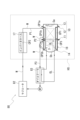
図1は、ユニット1を説明するスケルトン図である。
図2は、ユニット1の外観図である。
図3は、車両Vにおけるユニット1の配置を説明する図である。図3は、車両Vを右側から見た図を示している。
図4は、ユニット1の断面模式図である。図4は、インバータケースを取り除いた状態を示している。
図5は、デフケース50周りの拡大図である。
図6は、リングギア42周りの拡大図である。
図7は、ユニット1における冷却水Wの循環システム80を説明する図である。
図8は、冷却路CP1、CP3を説明する図である。図8は、図2と同じ方向から見たものを示している。図8では、第2ケース部材12及びカバー部材18を破線で示すと共に、インバータケースを省略している。また、図8の拡大図では、突起111c、141b1、厚肉部118、119及び厚肉部143、144の領域にハッチングを付して示している。
図9は、冷却路CP1、CP3を説明する図である。図9では、図2のユニットを上方から見たものを示している。図9では、第2ケース部材12及びカバー部材18を破線で示している。
図10は、デフケース50の回転を説明する図である。図10は、図6のA-A断面の模式図である。
図11は、デフケース50の回転を説明する図である。図11は、図6のB-B断面の模式図である。
図12は、車室VRとユニット1との位置関係を説明する図である。図12は、図3のA領域の拡大図である。図12では、冷却路CP3とリングギア42が設けられた領域を、それぞれ仮想線のクロスハッチングを付して示している。また、小径歯車部432を破線で示している。This embodiment will be described below.
FIG. 1 is a skeleton diagram illustrating the
FIG. 2 is an external view of the
FIG. 3 is a diagram illustrating the arrangement of the
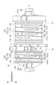
FIG. 4 is a schematic cross-sectional view of the
FIG. 5 is an enlarged view of the area around the
FIG. 6 is an enlarged view of the
FIG. 7 is a diagram illustrating a
FIG. 8 is a diagram illustrating the cooling paths CP1 and CP3. FIG. 8 shows what is seen from the same direction as FIG. In FIG. 8, the
FIG. 9 is a diagram illustrating the cooling paths CP1 and CP3. FIG. 9 shows the unit of FIG. 2 viewed from above. In FIG. 9, the
FIG. 10 is a diagram illustrating the rotation of the
FIG. 11 is a diagram illustrating the rotation of the
FIG. 12 is a diagram illustrating the positional relationship between the vehicle interior VR and the
図1に示すように、ユニット1は、モータ2と、モータ2が出力した動力を車両の駆動輪K、Kに伝達する動力伝達機構3と、モータ2の電力変換装置であるインバータIV(図2参照)を有する。
ユニット1のハウジングHSは、モータ2を収容するモータケース10の一部と、インバータIVを収容するインバータケース17が、一体に形成された形式の「3in1」ユニットである。As shown in FIG. 1, the
The housing HS of the
本実施形態では、図1に示すように、ユニット1は、動力伝達機構3として、遊星減速ギア4(減速歯車機構、遊星歯車機構)、差動機構5(差動歯車機構)および出力軸であるドライブシャフト9(9A、9B)を有する。
ユニット1では、モータ2の回転軸X回りの出力回転の伝達経路に沿って、遊星減速ギア4と、差動機構5と、ドライブシャフト9(9A、9B)と、が設けられている。ドライブシャフト9(9A、9B)の軸線は、モータ2の回転軸Xと同軸であり、差動機構5はモータ2と同軸である。In this embodiment, as shown in FIG. 1, the
In the
ユニット1では、モータ2の出力回転が、遊星減速ギア4で減速されて差動機構5に入力された後、ドライブシャフト9(9A、9B)を介して、ユニット1が搭載された車両の左右の駆動輪K、Kに伝達される。
ここで、遊星減速ギア4は、モータ2の下流に接続されている。差動機構5は、遊星減速ギア4を介してモータ2の下流に接続されている。ドライブシャフト9(9A、9B)は、差動機構5の下流に接続されている。In the
Here, the
図2に示すように、ユニット1のハウジングHSは、3in1タイプのハウジングであり、モータ2と、動力伝達機構3およびインバータIVを収容する。ハウジングHSは、1つ以上のケースから構成される。ハウジングHSは、例えば、モータ2を収容するモータケース10と、動力伝達機構3を収容するギアケース14と、インバータIVを収容するインバータケース17と、を有する。回転軸X方向におけるモータケース10の一端側に、ギアケース14が接合されている。ユニット1を車両に搭載した状態における、モータケース10の鉛直線VL方向上方には、インバータケース17が接合されている。
As shown in FIG. 2, the housing HS of the
インバータIVは、平滑コンデンサ、パワー半導体素子、ドライバ基板等を備えた電子部品である。インバータIVは、不図示の配線によってモータケース10内のモータ2と電気的に接続されている。
Inverter IV is an electronic component including a smoothing capacitor, a power semiconductor element, a driver board, and the like. Inverter IV is electrically connected to
図3に示すように、車両Vの車室VRは、ルーフパネル71と、フロアパネル72と、ダッシュパネル73と、で囲まれている。ユニット1は、車両前後方向における車室VRよりも前側に設けられており、車両Vの前輪に接続されている。ドライブシャフト9Bは、紙面手前側で、車両右側の駆動輪Kに接続される。図示は省略するが、ドライブシャフト9Aは、紙面奥側で、車両左側の駆動輪Kに接続される。
バッテリBは、フロアパネル72の下側に配置されている。バッテリBは、不図示の配線によってインバータケース17内のインバータIV(図2参照)と電気的に接続されている。
インバータケース17の最上面を通る水平線HL2は、フロアパネル72を通る水平線HL3よりも、鉛直線VL方向における下側に位置している。As shown in FIG. 3, the cabin VR of the vehicle V is surrounded by a
Battery B is arranged below the
A horizontal line HL2 passing through the top surface of the
モータ2は、軸方向視において、差動機構5(差動歯車機構)とオーバーラップする部分を有する(図4参照)。ここで、「軸方向視において」とは、回転軸X方向から視て、という意味である。
軸方向視において、モータ2は、遊星減速ギア4(減速歯車機構)にオーバーラップする部分を有する。
軸方向視において、遊星減速ギア4(減速歯車機構)は、差動機構5(差動歯車機構)にオーバーラップする部分を有する。
軸方向視において、遊星減速ギア4(減速歯車機構)は、モータ2にオーバーラップする部分を有する。
軸方向視において、差動機構5(差動歯車機構)は、遊星減速ギア4(減速歯車機構)にオーバーラップする部分を有する。
軸方向視において、差動機構5(差動歯車機構)は、モータ2にオーバーラップする部分を有する。
軸方向視において、モータ2は、差動機構5(差動歯車機構)とオーバーラップする部分を有する。The
When viewed in the axial direction, the
When viewed in the axial direction, the planetary reduction gear 4 (reduction gear mechanism) has a portion that overlaps the differential mechanism 5 (differential gear mechanism).
The planetary reduction gear 4 (reduction gear mechanism) has a portion that overlaps the
When viewed in the axial direction, the differential mechanism 5 (differential gear mechanism) has a portion that overlaps with the planetary reduction gear 4 (reduction gear mechanism).
The differential mechanism 5 (differential gear mechanism) has a portion that overlaps the
When viewed in the axial direction, the
図4に示すように、モータケース10は、第1ケース部材11と、第1ケース部材11に外挿される第2ケース部材12と、第1ケース部材11の一端に接合されるカバー部材13を有する。第1ケース部材11は、円筒状の支持壁部111と、支持壁部111の一端111aに設けられたフランジ状の接合部112と、を有している。
支持壁部111はモータ2の回転軸Xに沿わせた向きで設けられている。支持壁部111の内側には、モータ2が収容される。As shown in FIG. 4, the
The
第2ケース部材12は、円筒状の周壁部121と、周壁部121の一端121aに設けられたフランジ状の接合部122と、周壁部121の他端121bに設けられたフランジ状の接合部123と、を有している。
第2ケース部材12の周壁部121は、第1ケース部材11の支持壁部111に外挿可能な内径で形成されている。
第1ケース部材11と第2ケース部材12は、第1ケース部材11の支持壁部111に、第2ケース部材12の周壁部121を外挿して互いに組み付けられている。The
The
The
周壁部121の一端121a側の接合部122は、回転軸X方向から、第1ケース部材11の接合部112に当接している。これら接合部122、112は、ボルト(図示せず)で互いに連結されている。
The
図8に示すように、支持壁部111の一端111a側と他端111b側には、厚肉部118、119が設けられている。肉厚部118、119は、支持壁部111の外周から径方向外側に膨出している。肉厚部118、119の径方向の厚みH2は、支持壁部111の径方向の厚みH1(図4参照)よりも厚くなっている。
As shown in FIG. 8,
厚肉部118、119は、回転軸X周りの周方向における支持壁部111の全周に亘って設けられている。厚肉部118、119の外周面には、シール溝113、113がそれぞれ開口している。シール溝113、113は、回転軸X周りの周方向に沿って設けられており、厚肉部118、119の回転軸X周りの周方向の全周に亘ってそれぞれ設けられている。
The
図4に示すように、シール溝113、113には、シール材C、Cが外嵌して取り付けられている。これらシール材C、Cは、支持壁部111に外挿された周壁部121の内周に圧接して、支持壁部111の外周と、周壁部121の内周との間の隙間を封止する。
As shown in FIG. 4, sealing materials C, C are fitted and attached to the
図8に示すように、第1ケース部材11の支持壁部111の外周には、突起111cが設けられている。突起111cは、回転軸X方向における厚肉部118、119の間の領域に設けられている。回転軸Xの径方向における突起111cの径方向の厚み(突出高さ)は、厚肉部118、119の径方向の厚みH2と同じである。
As shown in FIG. 8, a
図9に示すように、突起111cは、回転軸X周りの周方向に延びると共に、回転軸Xを間隔を空けて囲む1つの壁である。突起111cは、回転軸X周りの周方向に沿って支持壁部111の全周に亘って設けられている。突起111cは、回転軸X周りの周方向で位相をずらして設けられており、支持壁部111の一端111a側から他端111b側に向かうにつれて回転軸X方向の位置が異なるらせん状に設けられている。径方向視において、突起111cは、回転軸Xに直交する直線Lp1から傾いた直線Lq1に沿って設けられている。直線Lp1と直線Lq1の成す角θ1は、らせんを形成するリード角である。
As shown in FIG. 9, the
支持壁部111の一端111a側では、突起111cは、接続壁111dを介して厚肉部118に接続されている。支持壁部111の他端111b側では、突起111cは、接続壁111eを介して厚肉部119に接続されている。接続壁111d、111eは、それぞれ回転軸Xに沿う向きに設けられている。回転軸Xの径方向における接続壁111d、111eの突出高さ(厚み)は、突起111c及び厚肉部118、119の厚みH2(図8参照)と同じである。
On the one
図8、図9に示すように、第1ケース部材11の支持壁部111に、第2ケース部材12の周壁部121が外挿される(図8、図9における破線参照)。
第2ケース部材12の周壁部121は、第1ケース部材11の支持壁部111の厚肉部118、119と、突起111cと、接続壁111d、111eとに当接する。As shown in FIGS. 8 and 9, the
The
これにより、周壁部121と支持壁部111の間には、支持壁部111の一端111a他端から他端111b側に向かって連続するらせん状の空間が形成される。このらせん状の空間によって、クーラントである冷却水W(図7参照)が通流する冷却路CP1が形成される。冷却水Wは支持壁部111を介して、支持壁部111の内部に収容されたモータ2と熱交換を行う。なお、図7ではらせん状の冷却路CP1を、簡略化して直線状に示している。
Thereby, a spiral space is formed between the
図9に示すように、冷却路CP1は、支持壁部111の一端111a側において、突起111cと厚肉部118と接続壁111dとで囲まれた部分が冷却水Wの入口CP1aとなる。また、冷却路CP1は、支持壁部111の他端111b側において、突起111cと厚肉部119と接続壁111eとで囲まれた部分が冷却水Wの出口CP1bとなる。冷却水Wの入口CP1aと出口CP1bが、それぞれらせん状の空間の始点と終点に相当する。
As shown in FIG. 9, in the cooling path CP1, a portion surrounded by the
図8に示すように、冷却路CP1の入口CP1aには、配管P1の一端が接続されている。配管P1の他端は、後記するインバータケース17の冷却路CP2に接続されている。また、冷却路CP1の出口CP1bには、配管P2の一端が接続されている。配管P2の他端は、後記するギアケース14の冷却路CP3に接続されている。
配管P1、P2は、それぞれ第2ケース部材12の周壁部121を貫通して設けられている。As shown in FIG. 8, one end of the pipe P1 is connected to the inlet CP1a of the cooling path CP1. The other end of the pipe P1 is connected to a cooling path CP2 of an
The pipes P1 and P2 are each provided to penetrate the
図4に示すように、第2ケース部材12の他端121bには、内径側に延びる壁部120(カバー)が設けられている。壁部120は、回転軸Xに直交する向きで設けられている。壁部120の回転軸Xと交差する領域に、ドライブシャフト9Aが挿通する開口120aが開口している。
As shown in FIG. 4, the
壁部120の、モータ2側(図中、右側)の面に、モータ2側に延びるモータ支持部125が設けられている。モータ支持部125は、開口120aを、間隔を開けて囲む筒状を成している。
モータ支持部125は、後記するコイルエンド253bの内側に挿入されている。モータ支持部125は、ロータコア21の端部21bに回転軸X方向の隙間をあけて対向している。モータ支持部125の内周には、ベアリングB1が支持されている。モータシャフト20の外周が、ベアリングB1を介してモータ支持部125で支持されている。A
The
壁部120の、差動機構5側(図中、左側)の面に、差動機構5側に延びる筒壁部126が設けられている。筒壁部126は、開口120aを囲む筒状である。筒壁部126の内周には、ベアリングB2が支持されている。ベアリングB2は、後記するデフケース50の筒壁部61を支持する。
A
図4に示すように、カバー部材13は、回転軸Xに直交する壁部130と、接合部132とを有する。
第1ケース部材11から見てカバー部材13は、差動機構5とは反対側(図中、右側)に位置している。カバー部材13の接合部132は、第1ケース部材11の接合部112に回転軸X方向から接合されている。カバー部材13と第1ケース部材11は、ボルト(図示せず)で互いに連結されている。この状態において第1ケース部材11は、支持壁部111の接合部112側(図中、右側)の開口が、カバー部材13で塞がれている。As shown in FIG. 4, the
When viewed from the
カバー部材13では、壁部130の中央部に、ドライブシャフト9Aの挿通孔130aが設けられている。
挿通孔130aの内周には、リップシールRSが設けられている。リップシールRSは、図示しないリップ部をドライブシャフト9Aの外周に弾発的に接触させている。挿通孔130aの内周と、ドライブシャフト9Aの外周との隙間が、リップシールRSにより封止されている。
壁部130における第1ケース部材11側(図中、左側)の面には、挿通孔130aを囲む周壁部131が設けられている。周壁部131の内周には、ドライブシャフト9AがベアリングB4を介して支持されている。In the
A lip seal RS is provided on the inner periphery of the
A
接合部132の内径側には、モータ支持部135および接続壁136が設けられている。モータ支持部135は、周壁部131から見てモータ2側(図中、左側)に設けられている。モータ支持部135は、回転軸Xを間隔を空けて囲む筒状を成している。
モータ支持部135の外周には、円筒状の接続壁136が接続されている。接続壁136は、壁部130側(図中、右側)の周壁部131よりも大きい外径で形成されている。接続壁136は、回転軸Xに沿う向きで設けられており、モータ2から離れる方向に延びている。接続壁136は、モータ支持部135と接合部132とを接続している。A
A
モータ支持部135の内側を、モータシャフト20の一端20a側が、モータ2側から周壁部131側に貫通している。
モータ支持部135の内周には、ベアリングB1が支持されている。モータシャフト20の外周が、ベアリングB1を介してモータ支持部135で支持されている。
ベアリングB1と隣り合う位置には、リップシールRSが設けられている。One
A bearing B1 is supported on the inner periphery of the
A lip seal RS is provided at a position adjacent to the bearing B1.
接続壁136の内周に、油孔136a、136bが開口している。接続壁136で囲まれた空間(内部空間Sc)に、油孔136aからオイルOLが流入する。内部空間Scに流入したオイルOLは、油孔136bから排出される。リップシールRSは、接続壁136内のオイルOLのモータ2側への流入を阻止するために設けられている。
図4に示すように、ギアケース14は、周壁部141と、周壁部141におけるモータケース10側の端部に設けられたフランジ状の接合部142と、を有している。周壁部141における接合部142とは反対側(図中左側)の端部には、後記するベアリングB2の支持部145が設けられている。周壁部141は、接合部142に接続する筒壁部141aと、支持部145に接続する傾斜部141c(傾斜面)と、これら筒壁部141aと傾斜部141cとを接続する接続壁部141bとを有する。筒壁部141aと接続壁部141bは、接合部142から段階的に縮径して傾斜部141cに接続する。傾斜部141cは、接続壁部141bから支持部145に向かって内径が小さくなる向きに傾斜している。動力伝達機構3である遊星減速ギア4と差動機構5は、周壁部141の内側に収容される。
As shown in FIG. 4, the
図6に示すように、ギアケース14の筒壁部141aと、接続壁部141bは、それぞれ回転軸Xに沿う向きに設けられている。筒壁部141aの外径は、接続壁部141bの外径よりも大径である。回転軸X方向における筒壁部141aと接続壁部141bとの境界は、回転軸Xに直交する段差面16となっている。
As shown in FIG. 6, the
ギアケース14には、カバー部材18が外挿されている。
カバー部材18は、円筒状の周壁部181と、周壁部181の一端181aに設けられたフランジ状の接合部182と、を有している。
カバー部材18の周壁部181は、ギアケース14の接続壁部141bに外挿可能な内径で形成されている。A
The
The
ギアケース14とカバー部材18は、ギアケース14の接続壁部141bに、カバー部材18の周壁部181を外挿して互いに組み付けられている。
カバー部材18の接合部182は、回転軸X方向から、ギアケース14の段差面16に接合されている。ギアケース14とカバー部材18は、ボルト(図示せず)で互いに連結されている。The
The
図8に示すように、接続壁部141bにおける筒壁部141a側の端部には、厚肉部143が設けられている。接続壁部141bにおける傾斜部141c側の端部には、厚肉部144が設けられている。肉厚部143、144は、接続壁部141bの外周から径方向外側に膨出している。肉厚部143、144の径方向の厚みH4は、接続壁部141bの径方向の厚みH3(図6参照)よりも厚くなっている。
As shown in FIG. 8, a
厚肉部143、144は、回転軸X周りの周方向における接続壁部141bの全周に亘って設けられている。厚肉部143、144の外周面には、シール溝146、146がそれぞれ開口している。シール溝146、146は、回転軸X周りの周方向に沿って設けられており、厚肉部143、144の回転軸X周りの周方向の全周に亘ってそれぞれ設けられている。
The
図6に示すように、シール溝146、146には、シール材C、Cが外嵌して取り付けられている。これらシール材C、Cは、接続壁部141bに外挿された周壁部181の内周に圧接して、接続壁部141bの外周と、周壁部181の内周との間の隙間を封止する。
As shown in FIG. 6, sealing materials C, C are externally fitted and attached to the
図8に示すように、ギアケース14の接続壁部141bの外周には、突起141b1が設けられている。突起141b1は、回転軸X方向における厚肉部143、144の間の領域に設けられている。回転軸Xの径方向における突起141b1の径方向の厚み(突出高さ)は、厚肉部143、144の径方向の厚みH4と同じである。
As shown in FIG. 8, a protrusion 141b1 is provided on the outer periphery of the
図9に示すように、突起141b1は、回転軸X周りの周方向に延びると共に、回転軸Xを間隔を空けて囲む1つの壁である。突起141b1は、回転軸X周りの周方向に沿って接続壁部141bの全周に亘って設けられている。突起141b1は、回転軸X周りの周方向で位相をずらして設けられており、筒壁部141a側から傾斜部141c側に向かうにつれて回転軸X方向の位置が異なるらせん状に設けられている。径方向視において、突起141b1は、回転軸Xに直交する直線Lp2から傾いた直線Lq2に沿って設けられている。直線Lp2と直線Lq2の成す角θ2は、らせんを形成するリード角である。
As shown in FIG. 9, the protrusion 141b1 is one wall that extends in the circumferential direction around the rotation axis X and surrounds the rotation axis X at intervals. The protrusion 141b1 is provided along the circumferential direction around the rotation axis X over the entire circumference of the
接続壁部141bの筒壁部141a側では、突起141b1は、接続壁141fを介して厚肉部143に接続されている。接続壁部141bの傾斜部141c側では、突起141b1は、接続壁141gを介して厚肉部144に接続されている。接続壁141f、141gは、それぞれ回転軸Xに沿う向きに設けられている。回転軸Xの径方向における接続壁141f、141gの突出高さ(厚み)は、突起141b1及び厚肉部143、144の厚みH4(図8参照)と同じである。
On the
図8、図9に示すように、ギアケース14の接続壁部141bに、カバー部材18の周壁部181が外挿される(図8、図9における破線参照)。
カバー部材18の周壁部181には、ギアケース14の接続壁部141bの厚肉部143、144と、突起141b1と、接続壁141f、141gとが当接する。As shown in FIGS. 8 and 9, the
The
これにより、周壁部181と接続壁部141bの間には、筒壁部141a側から傾斜部141c側に向かって連続するらせん状の空間が形成される。このらせん状の空間によって、クーラントである冷却水W(図7参照)が通流する冷却路CP3が形成される。冷却水Wは接続壁部141bを介して、接続壁部141bの内部に収容されている遊星減速ギア4(図4参照)と熱交換を行う。なお、図7ではらせん状の冷却路CP3を、簡略化して直線状に示している。
Thereby, a spiral space is formed between the
図9に示すように、冷却路CP3は、筒壁部141a側において、突起141b1と厚肉部143と接続壁141fとで囲まれた部分が冷却水Wの入口CP3aとなる。また、冷却路CP3は、傾斜部141c側において、突起141b1と厚肉部144と接続壁141gとで囲まれた部分が冷却水Wの出口CP3bとなる。冷却水Wの入口CP3aと出口CP3bが、それぞれらせん状の空間の始点と終点に相当する。
As shown in FIG. 9, in the cooling path CP3, a portion surrounded by the protrusion 141b1, the
図8に示すように、冷却路CP3の入口CP3aには、配管P2の他端が接続されている。配管P2の一端は、前記したモータケース10の冷却路CP1の出口CP1bに接続されている。また、冷却路CP3の出口CP3bには、配管P3の一端が接続されている。配管P3の他端は、後記するオイルクーラ83に接続されている。
配管P2、P3は、それぞれカバー部材18の周壁部181を貫通して設けられている。As shown in FIG. 8, the other end of the pipe P2 is connected to the inlet CP3a of the cooling path CP3. One end of the pipe P2 is connected to the outlet CP1b of the cooling path CP1 of the
The pipes P2 and P3 are each provided to penetrate the
図4に示すように、ギアケース14は、モータケース10から見て差動機構5側(図中、左側)に位置している。ギアケース14の接合部142は、モータケース10の第2ケース部材12の接合部123に、回転軸X方向から接合されている。ギアケース14と第2ケース部材12は、ボルト(図示せず)で互いに連結されている。ギアケース14の接合部142と、第2ケース部材12の接合部123との合わせ面Tは、回転軸Xに直交する。
回転軸Xの径方向からみて、冷却路CP1、CP3は、回転軸Xに沿って合わせ面Tから互いに離れる方向に延びている。As shown in FIG. 4, the
When viewed from the radial direction of the rotation axis X, the cooling passages CP1 and CP3 extend along the rotation axis X in a direction away from the mating surface T.
接合されたモータケース10およびギアケース14の内部に形成される空間は、第2ケース部材12の壁部120(カバー)によって、2つに区画される。壁部120のモータケース10側がモータ2を収容するモータ室Saであり、壁部120のギアケース14側が遊星減速ギア4と差動機構5を収容するギア室Sbである。カバーである壁部120は、ハウジングHSの内部において、モータ2と差動機構5に挟まれる。
The space formed inside the joined
ここでいうカバーは、ハウジングHS内に収容された部分を有するものであれば良く、壁部120のように、全体がハウジングHSに収容されていても良い。また、カバーは、たとえば、第2ケース部材12とは別体としてもよい。この場合、カバーは、モータケース10とギアケース14で挟んで固定しても良い。なお、カバーの一部がハウジングHS外に露出しても良い。
The cover here may have a portion housed in the housing HS, or may be entirely housed in the housing HS like the
図4に示すように、モータ2は、円筒状のモータシャフト20と、モータシャフト20に外挿された円筒状のロータコア21と、ロータコア21の外周を間隔を空けて囲むステータコア25と、を有する。
As shown in FIG. 4, the
モータシャフト20では、ロータコア21の両側に、ベアリングB1、B1が外挿されて固定されている。
ロータコア21から見てモータシャフト20の一端20a側(図中、右側)に位置するベアリングB1は、カバー部材13のモータ支持部135の内周に支持されている。他端20b側(図中、左側)に位置するベアリングB1は、第2ケース部材12の円筒状のモータ支持部125の内周に支持されている。In the
A bearing B1 located on the one
モータ支持部135、125は、後記するコイルエンド253a、253bの内径側に配置されている。モータ支持部135、125は、ロータコア21の一方の端部21aと他方の端部21bに、回転軸X方向の隙間をあけて対向して配置されている。
The
ロータコア21は、複数の珪素鋼板を積層して形成したものである。珪素鋼板の各々は、モータシャフト20との相対回転が規制された状態で、モータシャフト20に外挿されている。
モータシャフト20の回転軸X方向から見て、珪素鋼板はリング状を成している。珪素鋼板の外周側では、図示しないN極とS極の磁石が、回転軸X周りの周方向に交互に設けられている。The
When viewed from the direction of the rotation axis X of the
ロータコア21の外周を囲むステータコア25は、複数の電磁鋼板を積層して形成したものである。ステータコア25は、第1ケース部材11の円筒状の支持壁部111の内周に固定されている。
電磁鋼板の各々は、支持壁部111の内周に固定されたリング状のヨーク部251と、ヨーク部251の内周からロータコア21側に突出するティース部252と、を有している。The
Each of the electromagnetic steel plates has a ring-shaped
本実施形態では、巻線253を、複数のティース部252に跨がって分布巻きした構成のステータコア25を採用している。ステータコア25は、回転軸X方向に突出するコイルエンド253a、253bの分だけ、ロータコア21よりも回転軸X方向の長さが長くなっている。
In this embodiment, the
なお、ロータコア21側に突出する複数のティース部252の各々に、巻線を集中巻きした構成のステータコアを採用しても良い。
Note that a stator core having a configuration in which windings are concentratedly wound on each of the plurality of
第2ケース部材12の壁部120(モータ支持部125)には、開口120aが設けられている。モータシャフト20の他端20b側は、開口120aを差動機構5側(図中、左側)に貫通して、ギアケース14内に位置している。
モータシャフト20の他端20bは、ギアケース14の内側で、後記するサイドギア54Aに、回転軸X方向の隙間をあけて対向している。The wall portion 120 (motor support portion 125) of the
The
モータシャフト20と壁部120の開口120aの間にはリップシールRSが挿入されている。
ギアケース14の内径側には、遊星減速ギア4と差動機構5を潤滑するためのオイルOLが封入されている。
リップシールRSは、ギアケース14内のオイルOLがモータケース10内に流入することを阻止するために設けられている。A lip seal RS is inserted between the
Oil OL for lubricating the
The lip seal RS is provided to prevent oil OL in the
図5に示すように、モータシャフト20の、ギアケース14内に位置する領域に遊星減速ギア4のサンギア41がスプライン嵌合している。
As shown in FIG. 5, the
サンギア41の外周には歯部41aが形成されており、歯部41aには段付きピニオンギア43の大径歯車部431が噛合している。
A
段付きピニオンギア43は、サンギア41に噛合する大径歯車部431(ラージピニオン)と、大径歯車部431よりも小径の小径歯車部432(スモールピニオン)とを有している。
大径歯車部431と小径歯車部432は、回転軸Xに平行な軸線X1方向に並んで配置された、一体のギア部品である。The stepped
The large-
図6に示すように、大径歯車部431および小径歯車部432の内径側をピニオン軸44が貫通している。段付きピニオンギア43は、ピニオン軸44の外周にニードルベアリングNB、NBを介して回転可能に支持されている。
As shown in FIG. 6, the
小径歯車部432の歯部432aは、リングギア42の内周歯422に噛合している。リングギア42は、回転軸Xを間隔を空けて囲むリング状を成している。リングギア42の外周には、径方向外側に突出する複数の係合歯421が設けられている。複数の係合歯421は、回転軸X周りの周方向に間隔をあけて設けられている。
リングギア42は、外周に設けた係合歯421が、接続壁部141bの内周に設けた歯部146aにスプライン嵌合している。これにより、リングギア42は、回転軸X回りの回転が規制されている。The
In the
図5に示すように、差動機構5は、入力要素であるデフケース50(デファレンシャルケース)と、出力要素であるドライブシャフト(出力軸)、差動要素である差動歯車セットを有する。詳細な説明は省略するが、デフケース50は、回転軸X方向に組み付けられた2つのケース部材から構成しても良い。
As shown in FIG. 5, the
デフケース50は、遊星減速ギア4の段付きピニオンギア43を支持するキャリアとしても機能する。段付きピニオンギア43は、ピニオン軸44を介して、デフケース50に回転可能に支持されている。図11に示すように、3つの段付きピニオンギア43は、回転軸X周りの周方向に間隔を空けて配置されている。
The
図5に示すように、デフケース50内には、差動歯車セットとして、傘歯車式のデファレンシャルギアであるピニオンメートギア52と、サイドギア54A、54Bが設けられている。ピニオンメートギア52は、ピニオンメートシャフト51に支持されている。
ピニオンメートシャフト51は、回転軸X上に配置された中心部材510と、中心部材510の外径側に連結されたシャフト部材511を有する。図示は省略するが、複数のシャフト部材511が回転軸X周りの周方向に等間隔で設けられている。シャフト部材511は、デフケース50の径方向に延びる支持孔69に挿通され、支持されている。As shown in FIG. 5, a
The
ピニオンメートギア52は、シャフト部材511の各々に1つずつ外挿され、回転可能に支持されている。
One
図5に示すように、デフケース50では、回転軸X方向における中心部材510の一方側にサイドギア54Aが位置し、他方側にサイドギア54Bが位置する。サイドギア54A、54Bは、それぞれデフケース50に回転可能に支持される。
サイドギア54Aは、回転軸X方向における一方側から、ピニオンメートギア52に噛合している。サイドギア54Bは、回転軸X方向における他方側から、ピニオンメートギア52に噛合している。As shown in FIG. 5, in the
The
デフケース50の一端側(図中、右側)の中央部には、開口60と、開口60を囲む筒壁部61が設けられている。筒壁部61は、モータケース10側に延びている。筒壁部61の外周は、ベアリングB2を介して、第2ケース部材12の壁部120に支持されている。
デフケース50の内部には、開口60を挿通したドライブシャフト9Aが、回転軸X方向から挿入されている。An
A
図4に示すように、ドライブシャフト9Aは、カバー部材13の壁部130の挿通孔130aを貫通し、モータ2のモータシャフト20と、遊星減速ギア4のサンギア41(図5参照)の内径側を回転軸X方向に横切って設けられている。
As shown in FIG. 4, the
図5に示すように、デフケース50の他端側(図中、左側)の中央部には、貫通孔65と、貫通孔65を囲む筒壁部66が形成されている。筒壁部66に、ベアリングB2が外挿されている。筒壁部66に外挿されたベアリングB2は、ギアケース14の支持部145で保持されている。デフケース50の筒壁部66は、ベアリングB2を介して、ギアケース14で回転可能に支持されている。
As shown in FIG. 5, a through
支持部145には、ギアケース14の開口部145aを貫通したドライブシャフト9Bが、回転軸X方向から挿入されている。ドライブシャフト9Bは、支持部145で回転可能に支持されている。筒壁部66は、ドライブシャフト9Bの外周を支持する軸支持部として機能する。
開口部145aの内周には、リップシールRSが固定されている。リップシールRSの図示しないリップ部が、ドライブシャフト9Bに外挿されたサイドギア54Bの筒壁部540の外周に弾発的に接触している。
これにより、サイドギア54Bの筒壁部540の外周と開口部145aの内周との隙間が封止されている。The
A lip seal RS is fixed to the inner periphery of the
Thereby, a gap between the outer periphery of the
図5に示すように、デフケース50の内部では、ドライブシャフト9(9A、9B)の先端部が、回転軸X方向に間隔を空けて対向している。
ドライブシャフト9(9A、9B)の先端部の外周に、デフケース50に支持されたサイドギア54A、54Bがそれぞれスプライン嵌合している。サイドギア54A、54Bとドライブシャフト9(9A、9B)とが、回転軸X回りに一体回転可能に連結されている。As shown in FIG. 5, inside the
Side gears 54A and 54B supported by the
この状態においてサイドギア54A、54Bは、回転軸X方向で間隔をあけて、対向配置されている。サイドギア54A、54Bの間に、ピニオンメートシャフト51の中心部材510が位置している。
ピニオンメートシャフト51のピニオンメートギア52は、回転軸X方向の一方側に位置するサイドギア54Aおよび他方側に位置するサイドギア54Bに、互いの歯部を噛合させた状態で組み付けられている。In this state, the side gears 54A and 54B are disposed facing each other with an interval in the direction of the rotation axis X. A
The
図5に示すように、デフケース50の一端側(図中、右側)の、開口60の外径側に、ピニオン軸44の一端44a側の支持孔62が形成されている。デフケース50の他端側(図中、左側)には、ピニオン軸44の他端44b側の支持孔68が形成されている。
As shown in FIG. 5, a
支持孔62、68は、回転軸X方向にオーバーラップする位置に形成される。支持孔62、68は、それぞれ、段付きピニオンギア43を配置する位置に合わせて、回転軸X周りの周方向に間隔を空けて形成される。ピニオン軸44の一端44aが支持孔62に挿入され、他端44bが支持孔68に挿入される。ピニオン軸44は、他端44bが支持孔68に圧入されることで、ピニオン軸44はデフケース50に対して相対回転不能に固定されている。ピニオン軸44に外挿された段付きピニオンギア43は、回転軸Xに平行な軸線X1回りに回転可能に支持されている。
The support holes 62 and 68 are formed at positions that overlap in the rotation axis X direction. The support holes 62 and 68 are formed at intervals in the circumferential direction around the rotation axis X, respectively, in accordance with the position where the stepped
図5に示すように、ギアケース14の内部には、潤滑用のオイルOLが貯留されている。デフケース50が回転軸X回りに回転すると、オイルOLがデフケース50によって掻き上げられる。
詳細な説明は省略するが、デフケース50、ピニオン軸44等には、デフケース50に掻き上げられたオイルを導入するための油路、油孔等が設けられている。これによって、ベアリングB2、ニードルベアリングNB(図6参照)等の回転部材にオイルOLが導入されやすくなっている。As shown in FIG. 5, lubricating oil OL is stored inside the
Although detailed description will be omitted, the
また、図11に示すように、ギアケース14内の、デフケース50を収容する空間の上部に、キャッチタンク15が設けられている。キャッチタンク15は、回転軸Xと直交する鉛直線VLを挟んだ一方側(図中、右側)に位置している。キャッチタンク15は、連通口150を介してギア室Sbと連通している。デフケース50によって掻き上げられて飛散したオイルOLは、キャッチタンク15内に流入して捕集される。
Further, as shown in FIG. 11, a
図10に示すように、小径歯車部432の歯部432aは、ギアケース14の内周に固定されたリングギア42の内周歯422に噛合している。
図3に示すように、車両Vを右側から見て、ユニット1を搭載した車両Vが前進走行する場合、小径歯車部432は、図10に示すように、軸線X1回りの反時計回り方向に自転しながら、回転軸X周りの時計回り方向CWに公転する。これに合わせて、デフケース50は、回転軸X回りの時計回り方向CWに回転する。As shown in FIG. 10, the
As shown in FIG. 3, when the vehicle V equipped with the
図11に示すように、キャッチタンク15は、鉛直線VLを挟んだ右側、すなわちデフケース50の回転方向における下流側に位置している。これにより、回転軸X回りに回転するデフケース50で掻き上げられたオイルOLの多くが、キャッチタンク15内に流入できるようになっている。
キャッチタンク15は、不図示の油路、配管等を介して、オイルクーラ83(図7参照)に接続している。オイルクーラ83は、不図示の配管、油路等を介して、接続壁136に形成された油孔136a(図4参照)に接続している。As shown in FIG. 11, the
The
図4に示すように、ギアケース14の周壁部141には、油孔Haが形成されている。油孔Haは、不図示の配管を介して、内部空間Scに形成された油孔136bと接続している。油孔136bを介して内部空間Scから排出されたオイルOLは、油孔Haから再びギア室Sb内部に供給される。
As shown in FIG. 4, an oil hole Ha is formed in the
図10に示すように、小径歯車部432の歯部432aは、外径側でリングギア42の内周歯422に噛合している。リングギア42の係合歯421は、接続壁部141bの内周に設けた歯部146aにスプライン嵌合している。
As shown in FIG. 10, the
接続壁部141bには、カバー部材18の周壁部181が外挿されている。回転軸Xの径方向における接続壁部141bと周壁部181の間には、冷却路CP3が介在している。冷却路CP3は、回転軸X周りの周方向における全周に亘って接続壁部141bを囲んでいる。小径歯車部432の歯部432aと、リングギア42の内周歯422との噛合部は、回転軸Xの径方向で冷却路CP3とオーバーラップしている。
The
回転軸X方向から見て、大径歯車部431(図中、破線参照)の最外周が描く公転軌跡である仮想円Imは、周壁部181の内径R3よりも小径であり、かつ、接続壁部141bの外径R1よりも大径の直径R2を有している(R1<R2<R3)。
When viewed from the direction of the rotation axis It has a diameter R2 larger than the outer diameter R1 of the
図6に示すように、回転軸Xの径方向から見て、冷却路CP3は、回転軸X方向で大径歯車部431とオーバーラップしている。また、回転軸Xの径方向から見て、冷却路CP3は、リングギア42から回転軸X方向の傾斜部141c側にオフセットする部分を有する。
As shown in FIG. 6, when viewed from the radial direction of the rotation axis X, the cooling path CP3 overlaps the large
図7に示すように、ユニット1には、冷却水Wの循環システム80が設けられている。
循環システム80は、モータケース10の冷却路CP1、インバータケース17の冷却路CP2及びギアケース14の冷却路CP3との間で、冷却水Wを循環させる。循環システム80は、さらに、冷却路CP3と冷却路CP2の間に、オイルクーラ83、ウォーターポンプWPおよびラジエータ82を備えており、これらは冷却水Wが通流する配管等で接続されている。As shown in FIG. 7, the
The
ウォーターポンプWPは、冷却水Wを循環システム80内において圧送する。
ラジエータ82は、冷却水Wの熱を放熱して冷却する装置である。
オイルクーラ83は、冷却水Wと、オイルOLとの熱交換を行う熱交換器である。Water pump WP pumps cooling water W within
The
The
ウォーターポンプWPに圧送された冷却水Wは、インバータケース17内の冷却路CP2を通流した後に、モータケース10内の冷却路CP1と、ギアケース14の冷却路CP3を通って、オイルクーラ83に供給される。オイルクーラ83は、冷却水Wと、オイルOLとの熱交換を行うことで、オイルOLを冷却する。オイルクーラ83を通流した冷却水Wは、ラジエータ82で冷却されたあと、再びインバータケース17の冷却路CP2に供給される。
Cooling water W force-fed to water pump WP flows through cooling path CP2 in
ここで、図7に示すように、冷却路CP1は、入口CP1aで配管P1と接続されている。配管P1は、インバータケース17の冷却路CP2にも接続されている。また、冷却路CP1は、出口CP1bで第2ケース部材12を貫通する配管P2と接続されている。配管P2は、カバー部材18を貫通して冷却路CP3にも接続されている。
冷却路CP3は、入口CP3aで配管P2と接続されている。冷却路CP3は、出口CP3bでカバー部材18を貫通する配管P3と接続されている。配管P3は、オイルクーラ83にも接続されている。Here, as shown in FIG. 7, the cooling path CP1 is connected to the pipe P1 at the inlet CP1a. The pipe P1 is also connected to a cooling path CP2 of the
The cooling path CP3 is connected to the pipe P2 at an inlet CP3a. The cooling path CP3 is connected to a pipe P3 that penetrates the
インバータケース17の冷却路CP2から排出された冷却水Wは、配管P1を通って冷却路CP1の入口CP1aに供給される。冷却路CP1内では、冷却水Wは、入口CP1aから出口CP1bに向かって、モータケース10内をらせん状に移動する。
冷却水Wは、モータケース10内をらせん状に移動する過程で、モータ2の冷却を行う。The cooling water W discharged from the cooling path CP2 of the
The cooling water W cools the
冷却路CP1の出口CP1bに到達した冷却水Wは、配管P2から冷却路CP3に排出される。冷却路CP3内では、冷却水Wは、入口CP3aから出口CP3bに向かって、ギアケース14の外周をらせん状に移動する。
冷却水Wは、ギアケース14の外周をらせん状に移動する過程で、リングギア42周りの冷却を行う。
そして、冷却路CP3の出口CP3bに到達した冷却水Wは、配管P3からオイルクーラ83へ排出される。The cooling water W that has reached the outlet CP1b of the cooling path CP1 is discharged from the pipe P2 to the cooling path CP3. In the cooling path CP3, the cooling water W moves spirally around the outer periphery of the
The cooling water W cools the area around the
The cooling water W that has reached the outlet CP3b of the cooling path CP3 is discharged from the pipe P3 to the
かかる構成のユニット1の作用を説明する。
図1に示すように、ユニット1では、モータ2の出力回転の伝達経路に沿って、遊星減速ギア4と、差動機構5と、ドライブシャフト9A、9Bと、が設けられている。The operation of the
As shown in FIG. 1, in the
図4に示すように、モータ2が駆動されて、ロータコア21が回転軸X回りに回転すると、ロータコア21と一体にモータシャフト20が回転する。
図5に示すように、モータシャフト20の回転は、遊星減速ギア4のサンギア41に入力される。As shown in FIG. 4, when the
As shown in FIG. 5, the rotation of the
遊星減速ギア4では、サンギア41が、モータ2の出力回転の入力部となっており、段付きピニオンギア43を支持するデフケース50が、入力された回転の出力部となっている。
In the
図5に示すように、サンギア41が入力された回転で回転軸X回りに回転すると、段付きピニオンギア43(大径歯車部431、小径歯車部432)が、サンギア41側から入力される回転で、軸線X1回りに回転する。
ここで、段付きピニオンギア43の小径歯車部432は、ギアケース14の内周に固定されたリングギア42に噛合している。そのため、段付きピニオンギア43は、軸線X1回りに自転しながら、回転軸X周りに公転する。As shown in FIG. 5, when the
Here, the small
ここで、段付きピニオンギア43では、小径歯車部432の外径が大径歯車部431の外径よりも小さくなっている。
これにより、段付きピニオンギア43を支持するデフケース50が、モータ2側から入力された回転よりも低い回転速度で回転軸X回りに回転する。
そのため、遊星減速ギア4のサンギア41に入力された回転は、段付きピニオンギア43により、大きく減速されたのちに、デフケース50(差動機構5)に出力される。Here, in the stepped
As a result, the
Therefore, the rotation input to the
図5に示すように、デフケース50が入力された回転で回転軸X回りに回転することにより、デフケース50内で、ピニオンメートギア52と噛合するドライブシャフト9A、9Bが回転軸X回りに回転する。これによりユニット1が搭載された車両の左右の駆動輪K、K(図1参照)が、伝達された回転駆動力で回転する。
As shown in FIG. 5, when the
ギア室Sb内には、潤滑用のオイルOLが貯留される。モータ2の出力回転の伝達時に、ギア室Sb内に貯留されたオイルOLは、回転軸X回りに回転するデフケース50により掻き上げられる。掻き上げられたオイルOLにより、サンギア41と大径歯車部431との噛合部と、小径歯車部432とリングギア42との噛合部と、ピニオンメートギア52とサイドギア54A、54Bとの噛合部とが潤滑される。
Lubricating oil OL is stored in the gear chamber Sb. When the output rotation of the
図11に示すように、デフケース50は、回転軸X回りの時計回り方向CWに回転する。
ギアケース14の上部には、キャッチタンク15が設けられている。キャッチタンク15は、デフケース50の回転方向における下流側に位置しており、デフケース50で掻き上げられたオイルOLの一部は、キャッチタンク15内に流入する。As shown in FIG. 11, the
A
キャッチタンク15に流入したオイルOLは、不図示の配管を介してオイルクーラ83(図7参照)に導入され、冷却される。
図4に示すように、冷却されたオイルOLは、油孔136aを介して、接続壁136に形成された内部空間Scに供給される。内部空間Scに供給されたオイルOLは、ベアリングB4を潤滑し、油孔136bから排出される。油孔136bから排出されたオイルOLは、不図示の配管を介して、油孔Haからギア室Sb内に供給される。The oil OL that has flowed into the
As shown in FIG. 4, the cooled oil OL is supplied to the internal space Sc formed in the
ここで、図10に示すように、小径歯車部432は、歯部432aをリングギア42の内周歯422に噛合させながら軸線X1回りに自転することで、回転軸X周りに公転する。小径歯車部432とリングギア42は、歯部432aと内周歯422とが互いに噛合う際に発生する摩擦熱によって、温度が高くなる。
Here, as shown in FIG. 10, the small
小径歯車部432は回転軸X周りに公転するため、周期的にギア室Sbの下部に溜まったオイルOLを通過することで冷却される。
一方、リングギア42は、外周に設けた係合歯421が、接続壁部141bの内周に設けた歯部146aにスプライン嵌合しており、回転軸X回りの回転が規制されている。従って、リングギア42は、小径歯車部432よりもオイルOLによる冷却効果を得にくいため、温度が上がり易い。リングギア42の熱は、歯部146aから接続壁部141bに伝達される。Since the small
On the other hand, in the
図10に示すように、本実施形態では、接続壁部141bの外周側に冷却路CP3が位置している。リングギア42と接続壁部141bと冷却路CP3とは、回転軸Xの径方向でオーバーラップしている。そのため、リングギア42は、接続壁部141bを介して、冷却路CP3内を通流する冷却水Wと熱交換可能となっている。
As shown in FIG. 10, in this embodiment, the cooling path CP3 is located on the outer peripheral side of the
従って、小径歯車部432とリングギア42との噛合によって、リングギア42の温度が高くなっても、リングギア42は、冷却路CP3の冷却水Wの熱交換により冷却される。
Therefore, even if the temperature of the
また、リングギア42と小径歯車部432とが互いに噛合う際に噛合音Nが発生する。
図12に示すように、噛合音Nは、リングギア42から回転軸Xの径方向外側に放射状に伝搬する。噛合音Nの一部は、車室VR内に到達する。噛合音Nは、車両Vの乗員に音漏れ(ノイズ)として知覚される。Further, meshing noise N is generated when the
As shown in FIG. 12, the meshing sound N propagates radially outward from the
図12のクロスハッチングで示すように、冷却路CP3は、回転軸X回りの周方向において、リングギア42を全周に亘って囲んでいる。また、冷却路CP3を有するユニット1は、フロアパネル72とダッシュパネル73とによって車室VRと隔てられている。すなわち、冷却路CP3は、車室VRとリングギア42とに挟まれた部分を有する。
As shown by cross hatching in FIG. 12, the cooling path CP3 surrounds the
噛合音Nは、回転軸Xの径方向外側に伝搬する際に、冷却路CP3を径方向内径側から外径側に横断する。この際に、冷却路CP3内の冷却水Wが、噛合音Nの伝搬を遮蔽する遮蔽物として機能する。これにより、噛合音Nが車室VRへ到達することを低減できる。 When the meshing sound N propagates outward in the radial direction of the rotation axis X, it crosses the cooling path CP3 from the inner diameter side to the outer diameter side in the radial direction. At this time, the cooling water W in the cooling path CP3 functions as a shield that blocks the propagation of the meshing sound N. Thereby, it is possible to reduce the meshing sound N reaching the vehicle compartment VR.
また、図12に示すように、冷却路CP3は、回転軸X回りの周方向において、リングギア42を全周に亘って囲んでいる。すなわち、冷却路CP3は、回転軸Xを通る水平線HL1よりも上方に位置する部分を有している。
Moreover, as shown in FIG. 12, the cooling path CP3 surrounds the
ユニット1は、車室VRよりも鉛直線VL方向下側に設けられている。具体的には、インバータケース17の最上面を通る水平線HL2を、フロアパネル72を通る水平線HL3よりも、鉛直線VL方向下側に配置している。すなわち、冷却路CP3は、鉛直線VL方向で車室VRとリングギア42とに挟まれた部分を有する。これにより、車室VRの真下にユニット1を配置しても、噛合音Nが車室VRへ到達することを低減できる。
The
また、図8、図9に示すように、冷却路CP3を構成する突起141b1は、回転軸X周りの周方向に沿って接続壁部141bの全周に亘って設けられている。突起141b1は、筒壁部141a側から傾斜部141c側に向かうにつれて回転軸X方向の位置が異なるらせん状に設けられている。
Further, as shown in FIGS. 8 and 9, the protrusion 141b1 constituting the cooling path CP3 is provided along the circumferential direction around the rotation axis X over the entire circumference of the
リングギア42及び当該リングギア42を支持する接続壁部141bには、小径歯車部432の公転による遠心力が作用する。遠心力によって、接続壁部141bには、回転軸Xの径方向外側に広がる向きの応力が発生する。らせん状の突起141b1を接続壁部141bに設けることで、突起141b1がリブとして機能する。これにより、回転軸Xの径方向外側に広がる向きの応力に対する接続壁部141bの剛性を高めることができる。接続壁部141bの剛性を高めることで、ギアケース14の変形を低減することができる。また、小径歯車部432とリングギア42との噛み合いに伴い、リングギア42に発生する加振力による、ギアケース14の振動を低減することができて、ギアケース14が振動することによる音の発生を低減することができる。
Centrifugal force due to the revolution of the small-
また、突起141b1を設ける分、接続壁部141bにおけるリングギア42を支持する領域の体積を稼ぐ(厚みを増す)ことができる。これにより、ギアケース14そのものの噛合音Nの遮蔽機能も向上する。特に、図6に示すように、リングギア42と回転軸Xの径方向にオーバーラップする位置に突起141b1を設けることで、リングギア42から回転軸X方向にオフセットした位置に突起141b1を設ける場合よりも、噛合音Nの遮蔽効果は向上する。
Further, by providing the protrusion 141b1, the volume of the region of the
図3に示すように、ユニット1は、車両Vの前輪に接続されており、車両前後方向において車室VRよりも前側に配置されている。
図12に示すように、車両Vが前進走行すると、ユニット1は、車両前方から走行風Airを受ける。この場合、ユニット1のうち、回転軸Xを通る鉛直線VLよりも車両前方側の領域が、多くの走行風Airを受ける。ギアケース14もまた、回転軸Xを通る鉛直線VLよりも車両前方側の領域が、多くの走行風Airを受ける。ギアケース14の車両前方側で受けた走行風Airの多くは、水平線HL1よりも下側の領域を通って、車両後方に抜ける。As shown in FIG. 3, the
As shown in FIG. 12, when the vehicle V travels forward, the
前記した通り、冷却路CP3は、回転軸X回りの周方向において、リングギア42を全周に亘って囲んでいる。
すなわち、冷却路CP3は、車両前後方向における車室VRと反対側(鉛直線VLよりも車両前方側)においてリングギア42と径方向でオフセットした部分を有している。
また、冷却路CP3は、鉛直線VL方向における水平線HL1より下側において、リングギア42と径方向でオフセットした部分を有している。As described above, the cooling path CP3 surrounds the entire circumference of the
That is, the cooling path CP3 has a portion offset in the radial direction from the
Further, the cooling path CP3 has a portion offset in the radial direction from the
冷却路CP3内を通流する冷却水Wは、鉛直線VLよりも車両前方側の領域と、水平線HL1よりも下側の領域において、走行風Airとの熱交換により冷却される。
本実施形態にかかるユニット1は、前記したラジエータ82(図7参照)の他に、冷却路CP3を通る際に走行風Airを利用して冷却水Wを冷却できる分、冷却水Wの冷却効率が向上している。そのため、少ない量の冷却水Wでも効果的にユニット1を冷却できる。冷却効率を維持しつつユニット1に用いる冷却水Wの総量を減らすことができるため、ユニット1を軽量化できる。The cooling water W flowing through the cooling path CP3 is cooled by heat exchange with the traveling wind Air in a region in front of the vehicle relative to the vertical line VL and in a region below the horizontal line HL1.
In addition to the above-described radiator 82 (see FIG. 7), the
以下に、本発明のある態様におけるユニット1の例を列挙する。
(1)ユニット1は、遊星減速ギア4(遊星歯車機構)を収容するハウジングHSを有する。
ハウジングHSは、冷却水W(クーラント)が流れる冷却路CP3(流路)を有する。
遊星減速ギア4はハウジングHSに固定されたリングギア42を有する。
遊星減速ギア4の回転軸Xの径方向から視て(径方向視において)、冷却路CP3はリングギア42とオーバーラップする部分を有する。Below, examples of the
(1) The
The housing HS has a cooling path CP3 (flow path) through which cooling water W (coolant) flows.
The
When viewed from the radial direction of the rotation axis X of the planetary reduction gear 4 (in radial direction), the cooling path CP3 has a portion that overlaps with the
このように構成すると、リングギア42周辺のスペースを利用して冷却路CP3を配置することができる。これにより、ハウジングHSと冷却水Wとの接触面積が増加するので、熱交換効率が向上する。
具体的には、ハウジングHSにおける冷却路は、モータ2を冷却する冷却路CP1の部分と、リングギア42を冷却する冷却路CP3の部分と、を有する。冷却路CP3を設けた分だけ、冷却路CP1だけを有するハウジングHSよりも、ハウジングHSと冷却水Wとの接触面積を増加させている。これにより、発熱したユニット1と冷却水Wとの熱交換によるユニット1の冷却効率が向上する。すなわち、ユニット1における熱交換効率を向上させているといえる。With this configuration, the cooling path CP3 can be arranged using the space around the
Specifically, the cooling path in the housing HS includes a cooling path CP1 portion that cools the
また、冷却水Wが通流する冷却路CP3を、リングギア42の外周を囲むように設けることで、固定されたリングギア42と小径歯車部432との噛み合い部分に生ずる噛合音Nを、冷却水Wで低減できる。
具体的には、リングギア42と小径歯車部432との噛合音Nは、ハウジングHSの外部に伝搬される。そこで、リングギア42の外周側に冷却路CP3を設けることで、冷却路CP3内を通流する冷却水Wが、噛合音Nのうち、回転軸Xの径方向に伝搬する噛合音Nを遮蔽する遮蔽物として機能する。これにより、車室VRに噛合音Nが到達することを低減できる。In addition, by providing the cooling path CP3 through which the cooling water W flows so as to surround the outer periphery of the
Specifically, the meshing sound N between the
(2)回転軸Xの径方向から視て、ハウジングHSは、リングギア42とオーバーラップする領域に、突起141b1(突起部)を有する。
突起141b1は、冷却路CP3内に向けて突出している。
突起141b1は、回転軸X周りの周方向に沿って接続壁部141bの全周に亘って設けられている。
突起141b1は、筒壁部141a側から傾斜部141c側に向かうにつれて回転軸X方向の位置が異なるらせん状に設けられている。(2) When viewed from the radial direction of the rotation axis X, the housing HS has a protrusion 141b1 (protrusion) in a region overlapping with the
The protrusion 141b1 protrudes into the cooling path CP3.
The protrusion 141b1 is provided along the circumferential direction around the rotation axis X over the entire circumference of the
The protrusion 141b1 is provided in a spiral shape whose position in the rotation axis X direction changes from the
ギアケース14の接続壁部141bには、小径歯車部432の公転による遠心力が作用する。遠心力によって、接続壁部141bには、回転軸Xの径方向外側に広がる応力が発生する。そこで、上記のように構成して、接続壁部141bの外周にらせん状の突起141b1を設けることで、当該突起141b1は、リブとして機能する。これにより、回転軸Xの径方向外側に広がる応力に対するギアケース14の剛性を高めることができる。これにより、ギアケース14の剛性を高め、変形を低減することができる。また、歯車(小径歯車部432、リングギア42)の噛み合いに伴い、リングギア42に発生する加振力による、ギアケース14の振動を低減することができて、ギアケース14が振動することによる音の発生を低減することができる。
Centrifugal force due to the revolution of the small-
ここで、接続壁部141bから突出する突起141b1に代えて、カバー部材18の周壁部181の内周面から突出する突起をらせん状に設けて冷却路CP3を形成することも考えられる。しかしながら、突起をカバー部材18側に設けた場合、ギアケース14と別体になるため、リブとしての機能は発揮されずギアケース14の剛性を高めることにはならない。そのため、接続壁部141bに突起141b1を設ける方が好適である。
Here, instead of the protrusion 141b1 protruding from the
また、突起141b1を設ける分、接続壁部141bにおけるリングギア42を支持する領域の体積を稼ぐ(厚みを増す)ことができる。これにより、噛合音Nの伝搬を遮蔽する効果も高まるため、音対策に寄与できる。
Further, by providing the protrusion 141b1, the volume of the region of the
また、突起141b1が冷却路CP3の一部を構成することで、冷却路CP3内の冷却水Wとギアケース14との接触面積を増やすことができる。これにより、熱交換効率が向上する。
Moreover, since the protrusion 141b1 constitutes a part of the cooling path CP3, the contact area between the cooling water W in the cooling path CP3 and the
また、突起141b1が冷却路CP3の一部を構成することで、冷却路CP3内の空間を有効利用できる。冷却水Wとギアケース14との接触面積を確保しつつ、冷却路CP3をギアケース14のうちリングギア42の周りのみに局所的に設けることができる。これによりに、ユニット1の寸法の縮小に寄与する。
Furthermore, since the protrusion 141b1 constitutes a part of the cooling path CP3, the space within the cooling path CP3 can be effectively utilized. The cooling path CP3 can be locally provided only around the
なお、本実施形態では、突起141b1は、当該突起141b1の先端が周壁部181の内周に当接する高さH3を有する場合を例示したが、この態様に限定されない。突起141b1は、当該突起141b1の先端と周壁部181の内周面との間に僅かに隙間が形成される高さであっても良い。
In addition, in this embodiment, although the case where the protrusion 141b1 has the height H3 where the tip of the protrusion 141b1 contacts the inner periphery of the
(3)回転軸Xの径方向から視て、突起141b1のらせん状の部分が、回転軸Xの径方向でリングギア42とオーバーラップする。
(3) When viewed from the radial direction of the rotation axis X, the spiral portion of the protrusion 141b1 overlaps the
このように構成して、突起141b1をらせん状にすることで、冷却路CP3内の冷却水Wをスムーズに流すことができる。また、リングギア42とオーバーラップする位置に突起141b1を設けることで、リングギア42周りの接続壁部141bの体積を稼ぐことができる。
これにより、接続壁部141bそのものの噛合音Nの遮蔽効果が向上し、音対策に寄与できる。With this configuration and the protrusion 141b1 having a spiral shape, the cooling water W in the cooling path CP3 can flow smoothly. Further, by providing the protrusion 141b1 at a position overlapping the
This improves the shielding effect of the meshing sound N of the connecting
(4)ハウジングHSは、遊星減速ギア4の外周を囲むギアケース14を有する。
ギアケース14は、筒壁部141aと、筒壁部141aよりも外径が小さい接続壁部141bと、を有する。
筒壁部141aは、遊星減速ギア4の段付きピニオンギア43(ステップドピニオンギア)の大径歯車部431(ラージピニオンギア)を囲む領域である。
接続壁部141bは、筒壁部141aに接続すると共に、内周に遊星減速ギア4のリングギア42が固定された領域である。
回転軸X方向における筒壁部141aと接続壁部141bとの境界は段差面16となっている。
軸方向視において、冷却路CP3は、段差面16及び段付きピニオンギア43の大径歯車部431とオーバーラップする部分を有する。(4) The housing HS has a
The
The
The connecting
The boundary between the
When viewed in the axial direction, the cooling path CP3 has a portion that overlaps with the stepped
このように構成すると、筒壁部141aと接続壁部141bとの間の段差面16を利用して冷却路CP3を設けることができるので、回転軸Xの径方向のユニット1の寸法の縮小に寄与する。
With this configuration, the cooling path CP3 can be provided using the stepped
(5、6)ハウジングHSは、冷却路CP3を有するギアケース14(流路付ケース)と、ギアケース14と、回転軸X方向で対向するモータケース10(対向ケース)とを有する。
回転軸Xの径方向から視て、冷却路CP3は、ギアケース14とモータケース10との合わせ面Tから離れる方向に向かって延びる。
ハウジングHSの冷却路は、冷却路CP3と冷却路CP2を有する。(5, 6) The housing HS includes a gear case 14 (case with flow path) having a cooling path CP3, and a motor case 10 (opposed case) facing the
When viewed from the radial direction of the rotation axis X, the cooling path CP3 extends in a direction away from the mating surface T between the
The cooling path of the housing HS includes a cooling path CP3 and a cooling path CP2.
このように構成すると、モータケース10だけでなくギアケース14にも冷却路が設けられるので、冷却水WとハウジングHSとの接触面積を増やすことができ、熱交換効率を高めることができる。
また、冷却路CP3が、合わせ面Tから離れた位置から合わせ面Tから離れる方向に向かって延びているので、合わせ面T近辺からの冷却水Wのリークを減らすことができる。With this configuration, the cooling path is provided not only in the
Furthermore, since the cooling path CP3 extends from a position away from the mating surface T in a direction away from the mating surface T, leakage of the cooling water W from the vicinity of the mating surface T can be reduced.
(変形例1)
前記した実施形態にかかるユニット1では、ギアケース14における回転軸Xに略並行な領域である接続壁部141bに冷却路CP3が設けられたものを例示した。冷却路の配置は、この態様にのみ限定されない。
例えば、回転軸Xに略並行な領域である接続壁部141bから、回転軸Xに対して傾いた領域である傾斜部141cまでの範囲に、冷却路CP3が設けられたユニット1Aとしてもよい。なお、以下の変形例1では、原則として、前記した実施形態と異なる部分のみを説明する。(Modification 1)
In the
For example, the
図13は、変形例1に係るユニット1Aを説明する図である。
FIG. 13 is a diagram illustrating a
図13に示すように、ギアケース14Aの周壁部141は、回転軸X方向における接合部142と支持部145との間の領域である。
周壁部141は、接合部142側(図中、右側)から順番に、筒壁部141a、接続壁部141b、傾斜部141c、となっている。As shown in FIG. 13, the
The
接続壁部141bにおける筒壁部141a側の領域は、径方向の厚みが厚い厚肉部143となっている。厚肉部143の外周には、シール材Cが外嵌するシール溝146が開口している。
シール材Cが外嵌するシール溝146は、支持部145側の厚肉部144'にも設けられている。厚肉部144'は、支持部145の径方向の外周145bから径方向外側に膨出した部位である。支持部145において厚肉部144'は、回転軸X方向の端面145cと面一に設けられている。厚肉部144'は、回転軸X回りの周方向の全周に亘って設けられている。A region of the connecting
The
周壁部141では、接続壁部141bから傾斜部141cまでの範囲の外周に、突起147が設けられている。
突起147は、回転軸X周りの周方向に連続する一つの壁である。突起147は、回転軸X周りの周方向で位相をずらして設けられており、厚肉部143側から厚肉部144'側に向かうにつれて回転軸X方向の位置が異なるらせん状に設けられている。
回転軸Xの径方向における突起147の径方向の厚み(突出高さ)は、厚肉部143、144'の径方向の厚みH4と同じである。In the
The
The radial thickness (protrusion height) of the
ギアケース14Aでは、周壁部141の厚肉部143から、支持部145の厚肉部144'までの範囲が、カバー部材18Aが外挿されて組み付けられる領域となっている。
厚肉部143と突起147の間、回転軸X方向で隣接する突起147、147の間、突起147と厚肉部144'との間が、後記するカバー部材18aとの間に冷却路CP3を形成するための空間となっている。In the
A cooling path CP3 is formed between the
カバー部材18Aは、筒状の周壁部181と、接合部182と、筒状の傾斜部183と、筒壁部184と、を有する。
周壁部181は、ギアケース14における厚肉部143の外径と整合する内径で形成されている。接合部182は、周壁部181におけるモータケース10側の端部に接続されている。接合部182は、ギアケース14の筒壁部141aの外径と接合する外径で形成されている。The
The
傾斜部183は、周壁部181における接合部182とは反対側の端部に接続されている。傾斜部183は、回転軸X方向で周壁部181から離れるにつれて向かって内径が小さくなる向きに傾斜している。
傾斜部183は、ギアケース14Aの傾斜部141cの外形と整合する形状を有している。The
The
筒壁部184は、傾斜部183における周壁部181とは反対側の端部に接続されている。筒壁部184は、回転軸Xに沿う向きに設けられていると共に、ベアリングB2の支持部145を外挿可能な内径で形成されている。
The
カバー部材18Aは、回転軸X方向からギアケース14Aに外挿して組み付けられており、カバー部材18Aの接合部182を、ギアケース14A側の段差面16に当接させた位置で位置決めされる。
この状態において、ギアケース14A側の厚肉部143、厚肉部144'の外周に、カバー部材18A側の当接部182、筒壁部184がそれぞれ外挿されている。The
In this state, the
そして、カバー部材18Aの、周壁部181と傾斜部183の内周に、ギアケース14A側の突起147が当接しており、カバー部材18Aとギアケース14Aとの間に、冷却路CP3が形成されている。
この冷却路CP3は、周壁部181から傾斜部183までの範囲に、らせん状に形成される。The
This cooling path CP3 is formed in a spiral shape in a range from the
ここで、厚肉部143に設けたシール材Cが、当接部182の内周に当接して、厚肉部143の外周と当接部182の内周との隙間を封止している。
厚肉部144'に設けたシール材Cが、筒壁部184の内周に当接して、厚肉部144'の外周と筒壁部184の内周との隙間を封止している。
これにより、冷却路CP3を通流する冷却水Wの漏出が阻止されるようになっている。Here, the sealing material C provided on the
A sealing material C provided on the thick wall portion 144' contacts the inner periphery of the
This prevents the cooling water W flowing through the cooling path CP3 from leaking.
このように、ユニット1Aでは、モータケース10からギアケース14Aまでの範囲に、冷却路(CP1、CP3)が連続的に形成されている。特に、ギアケース14Aにおける傾斜部141cまで及んで、冷却路CP3が設けられている。
そのため、モータケース10側にのみ冷却路を設ける場合や、ギアケース14Aにおける接続壁部141bにのみ冷却路を設ける場合に比べて、冷却路の全長が長くなるので、冷却水Wとギアケース14Aとの接触面積を増やすことができる。
よって、発熱したユニット1Aと冷却水Wとの熱交換によるユニット1Aの冷却効率が向上する。すなわち、ユニット1Aにおける熱交換効率を向上させているといえる。
また、回転軸Xの径方向から見て、ギアケース14と冷却路CP3との重なる範囲が、前記したユニット1よりも大きくなる。
また、冷却水Wとギアケース14Aとの接触面積が増えた分だけ、冷却路CP3内を通流する冷却水Wが、回転軸Xの径方向に伝搬する噛合音Nを遮蔽する効果が大きくなる。
これにより、冷却水Wによる噛合音Nの遮蔽効果も高まる。In this way, in the
Therefore, the total length of the cooling path becomes longer than when the cooling path is provided only on the
Therefore, the cooling efficiency of the
Further, when viewed from the radial direction of the rotation axis X, the overlapping range of the
Furthermore, as the contact area between the cooling water W and the
Thereby, the effect of shielding the meshing sound N by the cooling water W is also enhanced.
(変形例2)
また、前記した実施形態では、冷却路CP1と別体に設けられた冷却路CP3でリングギア42を冷却するものを例示したが、この態様に限定されない。例えば、冷却路CP1を、ギアケース14B側に延長し、冷却路CP1でリングギア42の冷却も行うユニット1Bとしても良い。以下の変形例2では、本実施形態と異なる部分のみを説明する。(Modification 2)
Further, in the embodiment described above, the
図14は、変形例2に係るユニット1Bを説明する図である。
図14に示すように、ユニット1Bを構成するモータケース10Aは、第1ケース部材11Aと、第1ケース部材11Aに外挿される第2ケース部材12Aと、第1ケース部材11Aの一端に接合されるカバー部材13を有する。FIG. 14 is a diagram illustrating a
As shown in FIG. 14, the
第2ケース部材12Aは、円筒状の周壁部121と、周壁部121の一端121aに設けられたフランジ状の接合部122と、周壁部121の他端121bに設けられたフランジ状の接合部123と、を有している。
第2ケース部材12Aの周壁部121は、第1ケース部材11Aの支持壁部111に外挿可能な内径で形成されている。
第1ケース部材11Aと第2ケース部材12Aは、第1ケース部材11Aの支持壁部111に、第2ケース部材12Aの周壁部121を外挿して互いに組み付けられている。The
The
The
支持壁部111における一端111aと他端111bの間の領域には、内径側に延びる壁部110(カバー)が設けられている。壁部110は、回転軸Xに直交する向きで設けられている。壁部110の回転軸Xと交差する領域に、ドライブシャフト9Aが挿通する開口110aが開口している。
A wall portion 110 (cover) extending inwardly is provided in a region between one
壁部110の、モータ2側(図中、右側)の面に、モータ支持部115が設けられている。モータ支持部115は、開口110aを囲む筒状を成しており、回転軸Xに沿ってモータ2側に延びている。モータ支持部115の内周には、ベアリングB1が支持されている。モータシャフト20の外周が、ベアリングB1を介してモータ支持部115で支持されている。
A
壁部110の、デフケース50側(図中、左側)の面に、筒壁部116が設けられている。筒壁部116は、開口110aを囲む筒状を成しており、回転軸Xに沿ってデフケース50側に延びている。筒壁部116の内周には、ベアリングB2が支持されている。ベアリングB2は、デフケース50の筒壁部61の外周を支持している。
A
第1ケース部材11Aの支持壁部111の外周には、突起111cが設けられている。
突起111cは、回転軸X周りの周方向で位相をずらして設けられており、支持壁部111の一端111a側から他端111b側に向かうにつれて回転軸X方向の位置が異なるらせん状に設けられている。A
The
図14に示すように、第1ケース部材11Aの支持壁部111に、第2ケース部材12Aの周壁部121が外挿される。これにより、周壁部121と支持壁部111の間には、支持壁部111の一端111aから他端111b側に向かって連続するらせん状の空間が形成される。このらせん状の空間によって、冷却水Wが通流する冷却路CP1が形成される。
As shown in FIG. 14, the
周壁部121の他端121b側の接合部123には、回転軸X方向から、ギアケース14Bの接合部142が当接している。ギアケース14Bと第2ケース部材12Aは、ボルト(図示せず)で互いに連結されている。ギアケース14Bの接合部142と、第2ケース部材12Aの接合部123との合わせ面Tは、回転軸Xに直交する。
The
接合されたモータケース10Aおよびギアケース14Bの内部に形成される空間は、第1ケース部材11Aの壁部110(カバー)によって、2つに区画される。具体的には、支持壁部111と、壁部110と、カバー部材13とで囲まれた空間がモータ室Saとなる。また、支持壁部111と、壁部110と、ギアケース14Bとで囲まれた空間がギア室Sbとなる。
The space formed inside the joined
ここで、ギアケース14Bの接合部142は、回転軸X方向における、接続壁部141bと傾斜部141cの境界部に設けられている。接合部142は、接続壁部141bから回転軸Xの径方向外側に突出している。接続壁部141bは、第1ケース部材11Aの支持壁部111の内径と略整合する外径を有している。
Here, the
第2ケース部材12Aの接合部123と、ギアケース14Bの接合部142を回転軸X方向で互いに接合すると、接続壁部141bは、第1ケース部材11Aの支持壁部111に挿入される。接続壁部141bで支持されたリングギア42は、支持壁部111の内側に配置される。
冷却路CP1は、回転軸X方向におけるモータ2からリングギア42に及ぶ範囲に形成される。回転軸Xの径方向において、リングギア42は、冷却路CP1とオーバーラップしている。When the
The cooling path CP1 is formed in a range extending from the
回転軸Xの径方向からみて、冷却路CP1は、回転軸Xに沿って合わせ面Tからモータ2側に離れる方向に延びている。
このようにすると、冷却路CP1でモータ2の冷却とリングギア42の冷却を兼ねることができる。よって、カバー部材18、配管P2(図8参照)を省略できる分、部品点数を削減できる。When viewed from the radial direction of the rotation axis X, the cooling path CP1 extends along the rotation axis X in a direction away from the mating surface T toward the
In this way, the cooling path CP1 can serve both to cool the
また、冷却路CP1は、回転軸Xの径方向で、大径歯車部431ともオーバーラップしている。ギア室Sb内のオイルOLは、大径歯車部431が回転軸X周りの周方向に公転することで、大きく掻き上げられる。そのため、回転軸X周りの周方向におけるオイルOLの移動距離は、大径歯車部431で掻き上げられたものが、最も長くなる。従って、冷却路CP1内の冷却水WとオイルOLとの熱交換が行われる距離も長くなるため、ユニット1B全体の熱交換効率が向上する。
Moreover, the cooling path CP1 also overlaps with the large-
(変形例3)
前記した実施形態では、モータ2の出力回転の伝達経路上に、1つの遊星減速ギア4が設けられたものを例示したが、この態様に限定されない。例えば、図15に示すように、モータ2の出力回転の伝達経路上に2つの遊星減速ギア(第1遊星減速ギア4A、第2遊星減速ギア4B)を有するユニット1Cとしても良い。(Modification 3)
In the embodiment described above, one
図15は、変形例3に係るユニット1Cを説明する図である。なお、図15では、シール溝及びシール材は省略してある。
図15に示すように、第1遊星減速ギア4Aは、モータ2の下流に接続される。第2遊星減速ギア4Bは、第1遊星減速ギア4Aの下流に接続される。差動機構5は、第2遊星減速ギア4Bの下流に接続される。FIG. 15 is a diagram illustrating a
As shown in FIG. 15, the first
ユニット1Cは、モータ2を収容するモータケース10'と、第1遊星減速ギア4Aを収容する第1ギアケース14'と、第2遊星減速ギア4Bを収容する第2ギアケース14''と、を有している。
The
第1遊星減速ギア4Aは、ピニオンギア43Aを有している。第1遊星減速ギア4Aのピニオンギア43Aは、リングギア42Aと噛合う。リングギア42Aは、第1ギアケース14'に固定されている。
第2遊星減速ギア4Bは、段付きピニオンギア43Bを有している。段付きピニオンギア43Bの小径歯車部432Bは、リングギア42Bと噛合う。リングギア42Bは、第2ギアケース14''に固定されている。The first
The second
ユニット1Cでは、モータケース10'は、モータ2を囲む冷却路CP1を有している。第1ギアケース14'と第2ギアケース14''は、それぞれリングギア42A、42Bを囲む冷却路CP3A、CP3Bを有している。冷却路CP3Aは不図示の配管により冷却路CP1と接続されている。冷却路CP3Bは、不図示の配管により冷却路CP3Aと接続されている。また、冷却路CP3Bは、不図示の配管によりオイルクーラ83(図7参照)とも接続されている。冷却路CP1を通った冷却水Wは、冷却路CP3A、CP3Bを順番に通流したのち、オイルクーラ83へ排出される。
In the
これにより、冷却路CP3A、CP3B内を通流する冷却水Wによって、2つのリングギア42A、42B周りを冷却できる。また、リングギア42Aとピニオンギア43Aとの噛合により発生する噛合音と、リングギア42Bと小径歯車部432Bとの噛合により発生する噛合音を遮蔽できる。
なお、変形例3に係るユニット1Cでは、2つのリングギア42A、42Bのそれぞれに冷却路CP3A、CP3Bを有するものを例示したが、この態様に限定されない。少なくとも一方のリングギア周りに冷却路を有していればよい。リングギア周りに冷却路を設けない場合よりも、ユニット1Cにおける熱交換効率が向上すると共に、噛合音の遮蔽効果を高めることができるからである。Thereby, the surroundings of the two ring gears 42A and 42B can be cooled by the cooling water W flowing through the cooling paths CP3A and CP3B. Moreover, it is possible to shield the meshing noise generated by the meshing of the
In the
(その他の変形例)
また、前記した実施形態では、遊星減速ギア4が段付きピニオンギア43(ステップドピニオンギア)を有する場合を例示したが、この態様に限定されない。例えば、遊星減速ギア4は、ノンステップドギアで構成されたピニオンギアであっても良い。この場合、ピニオンギアは、径方向内径側でサンギア41と噛合し、径方向外径側でリングギア42と噛合う。
これにより、冷却路CP3内を通流する冷却水Wによって、リングギア42周りを冷却できる。(Other variations)
Further, in the embodiment described above, the case where the
Thereby, the area around the
なお、前記した実施形態では、ユニット1を車両Vに搭載した状態において、冷却路CP3の入口CP3aと出口CP3bを、モータ2の回転軸X(水平線HL)よりも鉛直線VL方向上方に設けたものを例示した(図8、図9参照)。本件発明は、この態様に限定されない。
例えば、冷却路CP3の入口CP3aをモータ2の回転軸X(水平線HL)よりも鉛直線VL方向上方に設け、出口CP3bをモータ2の回転軸X(水平線HL)よりも鉛直線VL方向下方に設けても良い。これにより、重力を利用して冷却水Wの流れをスムーズにすることができる。In addition, in the embodiment described above, when the
For example, the inlet CP3a of the cooling path CP3 is provided above the rotation axis X (horizontal line HL) of the
また、前記した実施形態では、突起141b1がらせん状であるものを例示したが、この態様に限定されない。例えば、突起141b1は、回転軸X方向に延びる線状の連続壁であり、回転軸X周りの周方向に間隔を空けて複数設けられていてもよい。これにより、回転軸X方向に沿う直線状の冷却路CP3が形成される。また、突起141b1は、連続壁ではなく、点状の突起を複数並べて線状となるように形成しても良い。これにより、冷却水Wは、突起の並ぶ方向にガイドされるからである。また、突起141b1は、回転軸X方向と回転軸X周りの周方向に幅を持たせた面状の連続壁としても良い。冷却水Wは、面状の連続壁を避けた位置を通流するようにガイドされるからである。 Further, in the embodiment described above, the protrusion 141b1 has a spiral shape, but the present invention is not limited to this embodiment. For example, the protrusions 141b1 are linear continuous walls extending in the direction of the rotation axis X, and a plurality of protrusions 141b1 may be provided at intervals in the circumferential direction around the rotation axis X. Thereby, a linear cooling path CP3 along the rotation axis X direction is formed. Moreover, the protrusion 141b1 may be formed not as a continuous wall but as a line formed by arranging a plurality of point-like protrusions. This is because the cooling water W is guided in the direction in which the protrusions are lined up. Further, the protrusion 141b1 may be a planar continuous wall having width in the rotation axis X direction and in the circumferential direction around the rotation axis X. This is because the cooling water W is guided so as to avoid the planar continuous wall.
また、前記した実施形態では、リングギア42はギアケース14と別体である場合を例示したが、この態様に限定されない。例えば、リングギア42は、ギアケース14と一体に形成されていても良い。
Further, in the embodiment described above, the case where the
また、前記した実施形態では、ユニット1が車両Vの前輪に接続されている場合を例示したが、この態様に限定されない(図3参照)。ユニット1は、車両Vの後輪に接続されていても良い。また、ユニット1は、車両Vの前輪と後輪にそれぞれ接続されていても良い。
Furthermore, in the embodiment described above, the case where the
本発明のある態様として、少なくとも動力伝達機構3を収容するハウジングHSを例とした。本発明の他の態様として、少なくともモータ2を収容するハウジングHSとしても良い。この場合、同一のハウジングHS内に動力伝達機構3が収容されていても良いし、収容させていなくても良い。
As an embodiment of the present invention, a housing HS that houses at least the
本発明の他の態様として、少なくともインバータIVを収容するハウジングHSとしても良い。この場合、同一のハウジングHS内に動力伝達機構3が収容されていても良いし、収容させていなくても良い。
As another aspect of the present invention, a housing HS may be used that accommodates at least the inverter IV. In this case, the
本発明の他の態様として、少なくともバッテリを収容するハウジングHSとしても良い。バッテリは、たとえば駆動用バッテリとすることができる。この場合、同一のハウジングHS内に動力伝達機構3が収容されていても良いし、収容されていなくても良い。
As another aspect of the present invention, it may be a housing HS that accommodates at least a battery. The battery can be, for example, a driving battery. In this case, the
本発明のある態様において、動力伝達機構3は、例えば、歯車機構、環状機構等を有する。
歯車機構は、例えば、減速歯車機構、増速歯車機構、差動歯車機構(差動機構)等を有する。
減速歯車機構及び増速歯車機構は、例えば、遊星歯車機構、平行歯車機構等を有する。
環状機構は、例えば、無端環状部品等を有する。
無端環状部品等は、例えば、チェーンスプロケット、ベルトとプーリ等を有する。In an embodiment of the present invention, the
The gear mechanism includes, for example, a reduction gear mechanism, a speed increase gear mechanism, a differential gear mechanism (differential mechanism), and the like.
The reduction gear mechanism and the speed increase gear mechanism include, for example, a planetary gear mechanism, a parallel gear mechanism, and the like.
The annular mechanism includes, for example, an endless annular component.
Endless annular parts and the like include, for example, chain sprockets, belts, and pulleys.
差動機構5は、例えば、傘歯車式のデファレンシャルギア、遊星歯車式のデファレンシャルギア等である。
差動機構5は、入力要素であるデファレンシャルケースと、出力要素である2つの出力軸と、差動要素である差動歯車セットと、を有する。
傘歯車式のデファレンシャルギアにおいて、差動歯車セットは傘歯車を有する。
遊星歯車式のデファレンシャルギアにおいて、差動歯車セットは遊星歯車を有する。The
The
In a bevel gear type differential gear, the differential gear set has a bevel gear.
In a planetary gear type differential gear, the differential gear set has planetary gears.
ユニット1は、デファレンシャルケースと一体回転するギアを有する。
例えば、平行歯車機構のうちのファイナルギア(デフリングギア)は、デファレンシャルケースと一体に回転する。例えば、遊星歯車機構のキャリアとデファレンシャルケースとが接続している場合、ピニオンギアがデファレンシャルケースと一体に回転(公転)する。The
For example, the final gear (differential ring gear) of the parallel gear mechanism rotates together with the differential case. For example, when the carrier of the planetary gear mechanism and the differential case are connected, the pinion gear rotates (revolutions) together with the differential case.
例えば、モータ2の下流に減速歯車機構が接続されている。減速歯車機構の下流に差動歯車機構が接続されている。即ち、モータ2の下流には、減速歯車機構を介して差動歯車機構が接続されている。なお、減速歯車機構に替えて増速歯車機構としても良い。
シングルピニオン型の遊星歯車機構は、例えば、サンギアを入力要素とし、リングギアを固定要素とし、キャリアを出力要素とすることができる。
ダブルピニオン型の遊星歯車機構は、例えば、サンギアを入力要素とし、リングギアを出力要素とし、キャリアを固定要素とすることができる。
シングルピニオン型又はダブルピニオン型の遊星歯車機構のピニオンギアは、例えば、ステップドピニオンギア、ノンステップドピニオンギア等を用いることができる。
ステップドピニオンギアは、ラージピニオンおよびとスモールピニオンとを有する。例えば、ラージピニオンをサンギアに噛合させると好適である。例えば、スモールピニオンをリングギアに嵌合させると好適である。
ノンステップドピニオンギアは、ステップドピニオンギアではない形式である。For example, a reduction gear mechanism is connected downstream of the
A single pinion type planetary gear mechanism can, for example, use a sun gear as an input element, a ring gear as a fixed element, and a carrier as an output element.
A double pinion type planetary gear mechanism can have, for example, a sun gear as an input element, a ring gear as an output element, and a carrier as a fixed element.
As the pinion gear of the single pinion type or double pinion type planetary gear mechanism, for example, a stepped pinion gear, a non-stepped pinion gear, etc. can be used.
The stepped pinion gear has a large pinion and a small pinion. For example, it is preferable to mesh the large pinion with the sun gear. For example, it is preferable to fit the small pinion into the ring gear.
A non-stepped pinion gear is a type of gear that is not a stepped pinion gear.
なお、本実施形態では、一例として、車両に搭載されたユニットを例示したが、この態様に限定されない。ユニットは、車両以外にも適用することができる。 In addition, in this embodiment, although the unit mounted on the vehicle was illustrated as an example, it is not limited to this aspect. The unit can also be applied to things other than vehicles.
以上、本発明の実施形態について説明したが、上記実施形態は本発明の適用例の一つを示したものに過ぎず、本発明の技術的範囲を上記実施形態の具体的構成に限定する趣旨ではない。発明の技術的な思想の範囲内で、適宜変更可能である。 Although the embodiments of the present invention have been described above, the above embodiments are merely examples of application of the present invention, and the technical scope of the present invention is limited to the specific configuration of the above embodiments. isn't it. Changes can be made as appropriate within the scope of the technical idea of the invention.
1、1A~1C :ユニット
10、10A :モータケース(対向ケース)
14、14A :ギアケース(流路付きケース)
141b1 :突起(突起部)
147 :突起(突起部)
4 :遊星減速ギア(遊星歯車機構)
42 :リングギア
43 :段付きピニオンギア(ステップドピニオンギア)
431 :大径歯車部(ラージピニオン)
CP3 :冷却路(流路)
HS :ハウジング
T :合わせ面
W :冷却水(クーラント)
X :回転軸1, 1A to 1C:
14, 14A: Gear case (case with flow path)
141b1: Protrusion (protrusion)
147: Protrusion (protrusion)
4: Planetary reduction gear (planetary gear mechanism)
42: Ring gear 43: Stepped pinion gear (stepped pinion gear)
431: Large diameter gear part (large pinion)
CP3: Cooling path (flow path)
HS :Housing T :Matching surface W :Cooling water (coolant)
X: Rotation axis
Claims (7)
前記ハウジングは、前記オイルと異なる材料で構成されたクーラントが流れる流路を有し、
前記遊星歯車機構は前記ハウジングに固定されたリングギアを有し、
径方向視において前記流路は前記リングギアとオーバーラップする部分を有する、ユニット。having a housing that accommodates oil and a planetary gear mechanism;
The housing has a flow path through which a coolant made of a material different from the oil flows,
the planetary gear mechanism has a ring gear fixed to the housing;
A unit in which the flow path has a portion that overlaps the ring gear when viewed in a radial direction.
径方向視において前記ハウジングは前記リングギアとオーバーラップする突起部を有し、
前記突起部は前記流路内に向けて突出する、ユニット。In claim 1,
The housing has a protrusion that overlaps the ring gear when viewed in a radial direction,
The unit, wherein the protrusion protrudes into the flow path.
径方向視において前記突起部のらせん状の部分が前記リングギアとオーバーラップする、ユニット。In claim 2,
A unit in which a spiral portion of the protrusion overlaps the ring gear when viewed in a radial direction.
軸方向視において前記流路は前記遊星歯車機構のステップドピニオンギアのラージピニオンギアとオーバーラップする、ユニット。In any one of claims 1 to 3,
The unit in which the flow path overlaps a large pinion gear of a stepped pinion gear of the planetary gear mechanism when viewed in the axial direction.
前記ハウジングは前記流路を有する流路付ケースと前記流路付ケースと対向する対向ケースとを有し、
径方向視において前記流路は前記流路付ケースと前記対向ケースとの合わせ面から離れる方向に向かって延びる、ユニット。In any one of claims 1 to 3,
The housing includes a case with a flow path having the flow path and an opposing case facing the case with the flow path,
In the unit, the flow path extends in a direction away from a mating surface of the case with the flow path and the opposing case when viewed in a radial direction.
前記ハウジングは前記流路を有する流路付ケースと前記流路付ケースと対向する対向ケースとを有し、
径方向視において前記流路は前記流路付ケースと前記対向ケースとの合わせ面から離れる方向に向かって延びる、ユニット。In claim 4,
The housing includes a case with a flow path having the flow path and an opposing case facing the case with the flow path,
In the unit, the flow path extends in a direction away from a mating surface of the case with the flow path and the opposing case when viewed in a radial direction.
前記流路は、前記クーラントが上方から下方に流れる部分を有する、ユニット。In any one of claims 1 to 3,
The unit, wherein the flow path has a portion through which the coolant flows from above to below.
Applications Claiming Priority (3)
| Application Number | Priority Date | Filing Date | Title |
|---|---|---|---|
| JP2021105242 | 2021-06-24 | ||
| JP2021105242 | 2021-06-24 | ||
| PCT/JP2022/021516 WO2022270216A1 (en) | 2021-06-24 | 2022-05-26 | Unit |
Publications (3)
| Publication Number | Publication Date |
|---|---|
| JPWO2022270216A1 JPWO2022270216A1 (en) | 2022-12-29 |
| JP7418940B2 true JP7418940B2 (en) | 2024-01-22 |
| JPWO2022270216A5 JPWO2022270216A5 (en) | 2024-01-30 |
Family
ID=84543824
Family Applications (1)
| Application Number | Title | Priority Date | Filing Date |
|---|---|---|---|
| JP2023529734A Active JP7418940B2 (en) | 2021-06-24 | 2022-05-26 | unit |
Country Status (3)
| Country | Link |
|---|---|
| JP (1) | JP7418940B2 (en) |
| CN (1) | CN117545946A (en) |
| WO (1) | WO2022270216A1 (en) |
Citations (3)
| Publication number | Priority date | Publication date | Assignee | Title |
|---|---|---|---|---|
| US20100320849A1 (en) | 2009-06-19 | 2010-12-23 | Gm Global Technology Operations, Inc. | Electronic drive unit |
| JP2011174583A (en) | 2010-02-25 | 2011-09-08 | Toyota Motor Corp | Vehicle power transmission device |
| WO2020032026A1 (en) | 2018-08-09 | 2020-02-13 | 日本電産株式会社 | Motor unit |
Family Cites Families (2)
| Publication number | Priority date | Publication date | Assignee | Title |
|---|---|---|---|---|
| JPH08319810A (en) * | 1995-05-25 | 1996-12-03 | Toyota Motor Corp | Lubricating device for power transmission device |
| JP4959354B2 (en) | 2007-01-29 | 2012-06-20 | 本田技研工業株式会社 | Hydraulic circuit for vehicle drive device |
-
2022
- 2022-05-26 JP JP2023529734A patent/JP7418940B2/en active Active
- 2022-05-26 WO PCT/JP2022/021516 patent/WO2022270216A1/en active Application Filing
- 2022-05-26 CN CN202280044953.0A patent/CN117545946A/en active Pending
Patent Citations (3)
| Publication number | Priority date | Publication date | Assignee | Title |
|---|---|---|---|---|
| US20100320849A1 (en) | 2009-06-19 | 2010-12-23 | Gm Global Technology Operations, Inc. | Electronic drive unit |
| JP2011174583A (en) | 2010-02-25 | 2011-09-08 | Toyota Motor Corp | Vehicle power transmission device |
| WO2020032026A1 (en) | 2018-08-09 | 2020-02-13 | 日本電産株式会社 | Motor unit |
Also Published As
| Publication number | Publication date |
|---|---|
| CN117545946A (en) | 2024-02-09 |
| JPWO2022270216A1 (en) | 2022-12-29 |
| WO2022270216A1 (en) | 2022-12-29 |
Similar Documents
| Publication | Publication Date | Title |
|---|---|---|
| WO2011155277A1 (en) | Drive device for vehicle | |
| US20210234416A1 (en) | Stator cooling structure | |
| JP7456382B2 (en) | motor unit | |
| JP2023153403A (en) | power transmission device | |
| JP7418940B2 (en) | unit | |
| JP7408889B2 (en) | vehicle | |
| JP7399602B2 (en) | unit | |
| WO2022270217A1 (en) | Unit | |
| JP7399603B2 (en) | unit | |
| JP7210115B2 (en) | power transmission device | |
| JP7451069B2 (en) | unit | |
| WO2022270101A1 (en) | Unit | |
| WO2022270215A1 (en) | Vehicle | |
| WO2022270212A1 (en) | Unit | |
| JP7471763B2 (en) | unit | |
| JP7471762B2 (en) | unit | |
| JP7471761B2 (en) | unit | |
| WO2022270061A1 (en) | Unit | |
| WO2022270060A1 (en) | Unit | |
| JP7437566B2 (en) | Vehicle drive system | |
| JP7433739B2 (en) | unit | |
| WO2022270059A1 (en) | Unit | |
| JP7321950B2 (en) | power transmission device | |
| US20230313877A1 (en) | Power transmission device | |
| WO2024075613A1 (en) | Vehicular drive device |
Legal Events
| Date | Code | Title | Description |
|---|---|---|---|
| A529 | Written submission of copy of amendment under article 34 pct |
Free format text: JAPANESE INTERMEDIATE CODE: A5211 Effective date: 20231030 |
|
| A621 | Written request for application examination |
Free format text: JAPANESE INTERMEDIATE CODE: A621 Effective date: 20231030 |
|
| A871 | Explanation of circumstances concerning accelerated examination |
Free format text: JAPANESE INTERMEDIATE CODE: A871 Effective date: 20231030 |
|
| TRDD | Decision of grant or rejection written | ||
| A01 | Written decision to grant a patent or to grant a registration (utility model) |
Free format text: JAPANESE INTERMEDIATE CODE: A01 Effective date: 20240109 |
|
| A61 | First payment of annual fees (during grant procedure) |
Free format text: JAPANESE INTERMEDIATE CODE: A61 Effective date: 20240109 |
|
| R150 | Certificate of patent or registration of utility model |
Ref document number: 7418940 Country of ref document: JP Free format text: JAPANESE INTERMEDIATE CODE: R150 |