WO2022270060A1 - Unit - Google Patents
Unit Download PDFInfo
- Publication number
- WO2022270060A1 WO2022270060A1 PCT/JP2022/012847 JP2022012847W WO2022270060A1 WO 2022270060 A1 WO2022270060 A1 WO 2022270060A1 JP 2022012847 W JP2022012847 W JP 2022012847W WO 2022270060 A1 WO2022270060 A1 WO 2022270060A1
- Authority
- WO
- WIPO (PCT)
- Prior art keywords
- gear
- motor
- oil
- rib
- rotation axis
- Prior art date
Links
- 230000005484 gravity Effects 0.000 claims description 27
- 238000005461 lubrication Methods 0.000 abstract description 12
- 239000003921 oil Substances 0.000 description 206
- 230000007246 mechanism Effects 0.000 description 49
- 230000002093 peripheral effect Effects 0.000 description 46
- 238000004891 communication Methods 0.000 description 36
- 238000005192 partition Methods 0.000 description 15
- 230000009467 reduction Effects 0.000 description 15
- 230000006870 function Effects 0.000 description 14
- 230000005540 biological transmission Effects 0.000 description 11
- 238000001816 cooling Methods 0.000 description 9
- 238000010586 diagram Methods 0.000 description 9
- 239000003566 sealing material Substances 0.000 description 8
- 230000007423 decrease Effects 0.000 description 5
- 229910000976 Electrical steel Inorganic materials 0.000 description 4
- 239000002826 coolant Substances 0.000 description 4
- 238000000926 separation method Methods 0.000 description 4
- 239000000463 material Substances 0.000 description 3
- 230000000717 retained effect Effects 0.000 description 3
- 229910000831 Steel Inorganic materials 0.000 description 2
- 238000013459 approach Methods 0.000 description 2
- 230000006872 improvement Effects 0.000 description 2
- 238000010030 laminating Methods 0.000 description 2
- 230000001050 lubricating effect Effects 0.000 description 2
- 239000010959 steel Substances 0.000 description 2
- 238000003756 stirring Methods 0.000 description 2
- 238000011144 upstream manufacturing Methods 0.000 description 2
- 238000004804 winding Methods 0.000 description 2
- 230000001133 acceleration Effects 0.000 description 1
- 230000000903 blocking effect Effects 0.000 description 1
- 230000008859 change Effects 0.000 description 1
- 238000006243 chemical reaction Methods 0.000 description 1
- 239000003638 chemical reducing agent Substances 0.000 description 1
- 239000000498 cooling water Substances 0.000 description 1
- 230000000994 depressogenic effect Effects 0.000 description 1
- 230000005611 electricity Effects 0.000 description 1
- 238000009434 installation Methods 0.000 description 1
- 239000007788 liquid Substances 0.000 description 1
- 230000007659 motor function Effects 0.000 description 1
- 239000003507 refrigerant Substances 0.000 description 1
- 238000007789 sealing Methods 0.000 description 1
Images


Classifications
-
- F—MECHANICAL ENGINEERING; LIGHTING; HEATING; WEAPONS; BLASTING
- F16—ENGINEERING ELEMENTS AND UNITS; GENERAL MEASURES FOR PRODUCING AND MAINTAINING EFFECTIVE FUNCTIONING OF MACHINES OR INSTALLATIONS; THERMAL INSULATION IN GENERAL
- F16H—GEARING
- F16H57/00—General details of gearing
- F16H57/04—Features relating to lubrication or cooling or heating
-
- H—ELECTRICITY
- H02—GENERATION; CONVERSION OR DISTRIBUTION OF ELECTRIC POWER
- H02K—DYNAMO-ELECTRIC MACHINES
- H02K7/00—Arrangements for handling mechanical energy structurally associated with dynamo-electric machines, e.g. structural association with mechanical driving motors or auxiliary dynamo-electric machines
- H02K7/10—Structural association with clutches, brakes, gears, pulleys or mechanical starters
- H02K7/116—Structural association with clutches, brakes, gears, pulleys or mechanical starters with gears
Definitions
- the present invention relates to units.
- Patent Document 1 discloses a speed reducer (unit) capable of cooling the heat-generating portion of an electric motor.
- One aspect of the invention is a housing containing a gear connected to the motor; a cover having a portion sandwiched between the gear and the motor; having a catch guide within the housing;
- the catch guide has an opening that opens toward the gear, A unit, wherein the catch guide has a portion that overlaps a radial side surface of the cover when viewed in a radial direction.
- the degree of freedom in lubrication design is improved.
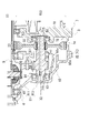
- FIG. 1 is a skeleton diagram showing a state in which the unit is mounted on a vehicle.
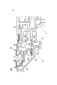
- FIG. 2 is a schematic cross-sectional view of the unit.
- FIG. 3 is a cross-sectional view showing an enlarged view of the unit around the catch tank.
- FIG. 4 is an enlarged cross-sectional view showing the periphery of the idler gear of the unit.
- FIG. 5 is a schematic cross-sectional view of the unit.
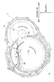
- FIG. 6 is a plan view of the gear case.
- FIG. 6 is a plan view of the gear case.
- FIG. 8 is a plan view of the cover.
- FIG. 9 is a diagram for explaining the flow of oil in the oil catch portion of the cover.
- FIG. 10 is a plan view of the cover.
- FIG. 11 is a perspective view of the intermediate case.
- FIG. 12 is a plan view of the intermediate case.
- FIG. 13 is a schematic diagram illustrating a catch tank.
- FIG. 14 is a diagram for explaining the function of the discharge holes provided in the catch tank.
- FIG. 15 is a cross-sectional view of the intermediate case.
- FIG. 16 is a diagram for explaining the flow of oil in the gear case.
- a motor unit is a unit having at least a motor.
- a power transmission device is a device having at least a power transmission mechanism, and the power transmission device is, for example, a gear mechanism and/or a differential gear mechanism.
- a unit that is a device comprising a motor and a power transmission belongs to the concept of both a motor unit and a power transmission.
- the “housing” contains the motor, gear, and inverter.
- a housing consists of one or more cases.
- "3 in 1” means a form in which a part of the motor case that houses the motor and a part of the inverter case that houses the inverter are integrally formed.
- the cover and the case constitute one case
- the case accommodating the motor and the case accommodating the inverter are integrally formed.
- a "motor” is a rotating electric machine that has a motor function and/or a generator function.
- a second element (part, portion, etc.) connected to the first element (part, portion, etc.); a second element (part, portion, etc.) connected downstream of the first element (part, portion, etc.);
- a second element (part, section, etc.) connected upstream of an element (part, section, etc.)
- the first element and the second element are power-transmittably connected.
- the power input side is upstream, and the power output side is downstream.
- the first element and the second element may be connected via another element (clutch, other gear mechanism, etc.).
- “Overlapping when viewed from a predetermined direction” means that a plurality of elements are arranged in a predetermined direction, and has the same meaning as “overlapping in a predetermined direction”.
- the "predetermined direction” is, for example, an axial direction, a radial direction, a gravitational direction, a vehicle running direction (vehicle forward direction, vehicle backward direction), or the like. If a drawing shows that multiple elements (parts, parts, etc.) are lined up in a predetermined direction, there is a sentence in the description explaining that they overlap when viewed in a predetermined direction. can be regarded as
- not overlapped when viewed from a predetermined direction and “offset when viewed from a predetermined direction” mean that a plurality of elements are not aligned in a predetermined direction, and "not overlapped in a predetermined direction”. , is synonymous with the description of "offset in a predetermined direction".
- the "predetermined direction” is, for example, an axial direction, a radial direction, a gravitational direction, a vehicle running direction (vehicle forward direction, vehicle backward direction), or the like. If a drawing shows that multiple elements (parts, parts, etc.) are not aligned in a predetermined direction, the description of the specification includes a sentence explaining that they do not overlap when viewed in a predetermined direction. can be regarded as
- the first element is located between the second element (part, portion, etc.) and the third element (part, portion, etc.) when viewed from a predetermined direction" In the case it means that the first element can be observed to be between the second and third elements.
- the "predetermined direction” includes an axial direction, a radial direction, a gravity direction, a vehicle running direction (vehicle forward direction, vehicle backward direction), and the like. For example, when the second element, the first element, and the third element are arranged in this order along the axial direction, the first element is between the second element and the third element when viewed in the radial direction.
- the drawing shows that the first element is between the second element and the third element when viewed from a predetermined direction
- the first element is the second element when viewed from a predetermined direction in the description of the specification. It can be considered that there is a sentence explaining what is between the third element.
- Axial direction means the axial direction of the rotation axis of the parts that make up the unit.
- Rotary direction means a direction perpendicular to the rotation axis of the parts that make up the unit.
- the parts are, for example, motors, gear mechanisms, differential gear mechanisms, and the like.
- the “downstream side in the rotational direction” means the downstream side in the rotational direction when the vehicle moves forward or the rotational direction when the vehicle moves backward. It is preferable to set it to the downstream side in the rotational direction when the vehicle moves forward, which occurs frequently.
- a "catch tank” is an element (part, part, etc.) that has the function of a tank (container) into which oil is introduced.
- the term “catch” refers to the fact that oil is supplied to the tank from the outside of the tank.
- the catch tank is provided, for example, using at least part of the housing, or is provided separately from the housing. Integrally forming the catch tank and the housing contributes to a reduction in the number of parts.
- Coolant is a refrigerant.
- it is a liquid (cooling water, etc.), a gas (air, etc.), or the like.
- Coolant is a concept that includes oil, but when both oil and coolant are used in this specification, it means that coolant is composed of a material different from that of oil.
- FIG. 1 is a skeleton diagram showing a state in which the unit 1 is mounted on a vehicle.
- FIG. 2 is a schematic cross-sectional view of the unit 1. As shown in FIG. FIG. 2 shows a section through the unit 1 such that the idler gear 3 and the differential 4 are shown in section.
- FIG. 3 is an enlarged cross-sectional view showing the surroundings of the catch tank CT4 of the unit 1.
- FIG. 4 is an enlarged cross-sectional view showing the periphery of the idler gear 3 of the unit 1.
- FIG. 5 is a cross-sectional view of the unit 1 in the direction of gravity VL when mounted on a vehicle.
- the unit 1 includes a motor 2, an idler gear 3 (reduction gear) that decelerates the output rotation of the motor 2 and inputs it to the differential device 4, drive shafts 5 (5A, 5B), and the motor 2 and an inverter INV, which is a power conversion device.
- a motor 2 an idler gear 3 (reduction gear) that decelerates the output rotation of the motor 2 and inputs it to the differential device 4, drive shafts 5 (5A, 5B), and the motor 2 and an inverter INV, which is a power conversion device.
- an idler gear 3, a differential gear 4, and drive shafts 5 (5A, 5B) are provided along the transmission path of the output rotation of the motor 2. As shown in FIG. The output rotation of the motor 2 is decelerated by the idler gear 3 and input to the differential gear 4, and then through the drive shafts 5 (5A, 5B) to the left and right drive wheels W, W of the vehicle on which the unit 1 is mounted. is transmitted to
- the idler gear 3 is connected downstream of the motor 2.
- the differential gear 4 is connected downstream of the idler gear 3 .
- a drive shaft 5 ( 5 A, 5 B) is connected downstream of the differential gear 4 .
- the housing HS of the unit 1 has a motor case 6 , an intermediate case 7 , a gear case 8 and a cover 9 .
- the housing HS accommodates an oil OL used for cooling and lubrication, and a gear train (idler gear 3, differential gear 4) as a power transmission mechanism.
- the motor 2 is housed in the motor case 6 of the housing HS.
- the gear case 8 accommodates a gear train (idler gear 3, differential gear 4) as a power transmission mechanism.
- Oil OL used for cooling and lubrication is contained in at least one of motor case 6 and gear case 8 .
- the intermediate case 7 has a cylindrical peripheral wall portion 71 and a wall portion 72 .
- the intermediate case 7 is arranged such that the peripheral wall portion 71 is oriented along the rotation axis X1 of the drive shaft 5 (5A, 5B).
- the peripheral wall portion 71 surrounds the rotation axis X1 with a space therebetween.
- the peripheral wall portion 71 is provided with a joint portion 711 with the motor case 6 at one end in the direction of the rotation axis X1.
- a joint portion 712 with the gear case 8 is provided at the other end portion of the peripheral wall portion 71 in the direction of the rotation axis X1.
- a wall portion 72 is provided in a region between the joint portions 711 and 712 of the peripheral wall portion 71 .
- the wall portion 72 extends inward from the inner circumference of the peripheral wall portion 71 .
- the wall portion 72 is provided in a direction orthogonal to the rotation axis X1.
- the wall portion 72 is provided in a range that crosses the rotation axis X1 of the drive shafts 5 (5A, 5B) and the rotation axis X2 of the idler gear 3. As shown in FIG.
- the wall portion 72 corresponds to a wall portion sandwiched between the final gear FG (gear) and the motor 2 in the housing HS.
- a through hole 70 is provided in a region of the wall portion 72 that intersects with the rotation axis X1.
- the through-hole 70 penetrates the wall portion 72 in the thickness direction (rotational axis X1 direction: left-right direction in the figure).
- a cylindrical motor support portion 74 surrounding the through hole 70 is provided on the surface of the wall portion 72 on the side of the motor case 6 (right side in the figure).
- the motor support portion 74 is formed with an inner diameter larger than that of the through hole 70 , and the bearing B ⁇ b>1 is supported on the inner circumference of the motor support portion 74 .
- the motor case 6 has a cylindrical peripheral wall portion 61 and a wall portion 62 .
- the motor case 6 is provided with the peripheral wall portion 61 oriented along the rotation axis X1.
- the peripheral wall portion 61 surrounds the rotation axis X1 with a space therebetween.
- a wall portion 62 is provided at one end in the direction of the rotation axis X1, and a joint portion 611 with the intermediate case 7 is provided at the other end in the direction of the rotation axis X1.
- the wall portion 62 extends radially inward from one end of the peripheral wall portion 61 in the direction of the rotation axis X1.
- the wall portion 62 is provided in a direction orthogonal to the rotation axis X1.
- a through hole 60 is provided in a region of the wall portion 62 that intersects with the rotation axis X1. The through hole 60 penetrates the wall portion 62 in the thickness direction (horizontal direction in the figure).
- a tubular wall portion 63 surrounding the through-hole 60 is provided on the outer surface (the right surface in the drawing) of the wall portion 62 .
- the cylindrical wall portion 63 extends along the rotation axis X to the outside of the housing HS (to the right in the drawing).
- a lip seal RS is provided on the inner circumference of the cylinder wall portion 63 . The lip seal RS seals the gap between the inner periphery of the cylinder wall portion 63 and the outer periphery of the drive shaft 5A.
- a cylindrical motor support portion 64 surrounding the through-hole 60 is provided on the inner side surface (the left side surface in the drawing) of the wall portion 62 .
- the motor support portion 64 extends inside the housing HS (leftward in the drawing) along the rotation axis X1.
- the motor support portion 64 is formed with an inner diameter larger than that of the through hole 60 , and the bearing B ⁇ b>1 is supported on the inner circumference of the motor support portion 64 .
- an oil hole 641 is opened in a region between the bearing B1 and the lip seal RS. Oil OL captured in a catch tank CT2, which will be described later, is supplied to the oil hole 641 through a pipe (not shown) attached to the housing HS.
- the motor case 6 and the intermediate case 7 are assembled with their joint portions 611 and 711 joined together in the direction of the rotation axis X1.
- the space between the wall portions 62 and 72 inside the peripheral wall portion 61 and the peripheral wall portion 71 serves as a motor chamber Sa in which the motor 2 is accommodated.
- the motor 2 has a cylindrical motor shaft 20, a cylindrical rotor core 21 fitted onto the motor shaft 20, and a stator core 22 surrounding the outer circumference of the rotor core 21 with a gap.
- the motor shaft 20 is a tubular member fitted over the drive shaft 5A.
- One end 20a of the motor shaft 20 in the longitudinal direction is a supported portion 201 by the bearing B1, and the other end 20b is a connecting portion 202 to the input gear .
- the inner peripheries of the supported portion 201 and the connecting portion 202 are supported by needle bearings NB, NB externally inserted on the drive shaft 5A. In this state, the motor shaft 20 is rotatable relative to the drive shaft 5A.
- a bearing B1 is externally inserted and positioned on the outer periphery of the supported portion 201 on the side of the end portion 20a. Furthermore, in the motor shaft 20, a bearing B1 is externally inserted and positioned on the outer circumference of the position away from the end 20b toward the end 20a (right side in the drawing).
- the motor shaft 20 is rotatably supported by motor supports 64 and 74 via bearings B1 and B1 at one end 20a and the other end 20b in the longitudinal direction.
- a rotor core 21 is fixed to the motor shaft 20 in a region between the bearings B1, B1 in the direction of the rotation axis X1.
- the rotor core 21 is formed by laminating a plurality of silicon steel plates. Each of the silicon steel plates is fitted over the motor shaft 20 in a state where relative rotation with the motor shaft 20 is restricted.
- the silicon steel plate has a ring shape when viewed from the direction of the rotation axis X1.
- N-pole and S-pole magnets are provided alternately in the circumferential direction around the rotation axis X on the outer peripheral side of the silicon steel plate.
- the end portion 21b of the rotor core 21 in the direction of the rotation axis X1 is positioned by the large diameter portion 203 of the motor shaft 20.
- An end portion 21 a of the rotor core 21 is positioned by a stopper 24 press-fitted onto the motor shaft 20 .
- a stator core 22 is positioned radially outside the rotor core 21 .
- the stator core 22 is formed by laminating a plurality of electromagnetic steel sheets.
- Each of the electromagnetic steel sheets has a ring-shaped yoke portion 221 and teeth portions 222 protruding from the inner circumference of the yoke portion 221 toward the rotor core 21 side.
- the stator core 22 having a configuration in which the windings 223 are distributed over a plurality of teeth 222 is adopted.
- the stator core 22 is longer than the rotor core 21 in the direction of the rotation axis X1 by coil ends 223a and 223b projecting in the direction of the rotation axis X1.
- a stator core in which windings are concentratedly wound may be employed for each of the plurality of tooth portions 222 protruding toward the rotor core 21 side.
- the yoke portion 221 of the stator core 22 is inserted into the inner periphery of the peripheral wall portion 61 of the motor case 6 from the intermediate case 7 side.
- a stepped portion 612 is provided on the inner periphery of the peripheral wall portion 61 .
- the stator core 22 is positioned at a position where the yoke portion 221 is in contact with the stepped portion 612 on the side of the peripheral wall portion 61 .
- the inner circumference 222c of the tooth portion 222 of the stator core 22 faces the outer circumference of the rotor core 21 with a small air gap CL (clearance) between the inner circumference 222c and the outer circumference 21c of the rotor core 21.
- the peripheral wall portion 61 of the motor case 6 is formed with a communication groove 65 on the inner circumference of the lower region in the direction of gravity VL.
- the communication groove 65 is provided in the peripheral wall portion 61 at one location in the circumferential direction around the rotation axis X1.
- the communication groove 65 extends along the rotation axis X direction on the outer diameter side of the yoke portion 221 of the stator core 22 .
- a plurality of communication grooves 65 may be provided.
- a plurality of communication grooves 65 may be provided in a lower region of the peripheral wall portion 61 at intervals in the circumferential direction around the rotation axis X1.
- the lower space of the motor chamber Sa is divided into a space on one side (first space Sa1) and a space on the other side (second space Sa2) with the yoke portion 221 interposed therebetween. Since the stator core 22 is positioned between the first space Sa1 and the second space Sa2, it is difficult for the oil OL to move between the first space Sa1 and the second space Sa2.
- a communication groove 65 is provided in a lower region of the peripheral wall portion 61 in the gravitational direction VL, more preferably in a lowermost region.
- the oil OL can be moved between the first space Sa1 and the second space Sa2 via the communication groove 65. As shown in FIG. Therefore, the oil OL can be easily moved between the first space Sa1 and the second space Sa2.
- the motor support portions 64 and 74 are inserted from the direction of the rotation axis X1 on the inner diameter side (rotation axis X1 side) of the coil ends 223a and 223b of the stator core 22. As shown in FIG.
- the motor support portions 64, 74 are formed with an outer diameter smaller than the inner diameter of the coil ends 223a, 223b. Tip ends 64a and 74a of the motor support portions 64 and 74 face the end portions 21a and 21b of the rotor core 21 with a gap in the direction of the rotation axis X1.
- the other end 20b side of the motor shaft 20 to which the rotor core 21 is externally inserted passes through the through hole 70 of the intermediate case 7 from the motor case 6 side to the gear case 8 side (left side in the drawing).
- the end portion 20b of the motor shaft 20 faces the cylindrical support portion 401 of the differential gear 4 with a gap in the rotation axis X1 direction.
- the input gear 23 is spline-fitted to the outer circumference of the connecting portion 202 on the end portion 20b side.
- the input gear 23 is positioned in the rotation axis X1 direction by a nut N screwed onto the outer periphery of the connecting portion 202 .
- the large gear 33 of the idler gear 3 meshes with the outer periphery of the input gear 23 so as to transmit rotation.
- the large gear 33 in the idler gear 3 is spline-fitted to the outer periphery of the cylindrical shaft portion 31 .
- Bearings B3 and B3 are externally fitted to one end 31a and the other end 31b of the shaft portion 31 in the longitudinal direction.
- the bearing B3 externally fitted on the end portion 31a of the shaft portion 31 is inserted into the cylindrical support portion 75 of the intermediate case 7. As shown in FIG.
- the end portion 31a side of the shaft portion 31 is rotatably supported by the support portion 75 of the intermediate case 7 via the bearing B3.
- the bearing B3 externally inserted on the end portion 31b of the shaft portion 31 is inserted into the cylindrical support portion 84 of the gear case 8.
- An end portion 31b of the shaft portion 31 is rotatably supported by a support portion 84 of the gear case 8 via a bearing B3.
- the shaft portion 31 of the idler gear 3 is provided along the rotation axis X2 parallel to the rotation axis X1.
- the shaft portion 31 of the idler gear 3 rotates around the rotation axis X2 when the output rotation of the motor 2 is input through the large gear 33 .
- a small gear 32 is provided on the shaft portion 31 at a position away from the large gear 33 toward the end portion 31b (left side in the drawing).
- the small gear 32 is formed integrally with the shaft portion 31 and has an outer diameter R32 smaller than the outer diameter R33 of the large gear 33 .
- the small gear 32 meshes with a final gear FG fixed to a differential case 40 of the differential gear 4 so as to transmit rotation.
- the differential case 40 is formed in a hollow shape that accommodates therein a shaft 41, bevel gears 42A and 42B, and side gears 43A and 43B.
- cylindrical support portions 401 and 402 are provided on both sides in the direction of the rotation axis X1 (horizontal direction in the figure). The support portions 401 and 402 extend away from the shaft 41 along the rotation axis X1.
- a bearing B ⁇ b>2 is extrapolated to the support portion 402 of the differential case 40 .
- the bearing B ⁇ b>2 is supported on the inner periphery of the cylindrical support portion 83 of the gear case 8 .
- a support portion 402 of the differential case 40 is rotatably supported by the gear case 8 via a bearing B2.
- the drive shaft 5B passing through the opening 80 of the gear case 8 is inserted into the support portion 402 from the rotation axis X1 direction, and the drive shaft 5B is rotatably supported by the support portion 402 .
- a lip seal RS is fixed to the inner circumference of the opening 80, and the gap between the outer circumference of the drive shaft 5A and the inner circumference of the opening 80 is sealed with the lip seal RS.
- a bearing B2 is externally fitted to the support portion 401 of the differential case 40.
- the bearing B ⁇ b>2 externally inserted on the support portion 401 is supported on the inner periphery of the ring-shaped support portion 92 of the cover 9 .
- a support portion 401 of the differential case 40 is rotatably supported by the cover 9 via a bearing B2.
- the drive shaft 5A passing through the through hole 60 (see FIG. 2) of the motor case 6 is inserted into the support portion 401 of the differential case 40 from the direction of the rotation axis X1.
- the drive shaft 5A is provided across the motor shaft 20 of the motor 2, the inner diameter side of the input gear 23, and the cover 9 in the rotation axis X1 direction. Supported.
- side gears 43A and 43B are spline-fitted to the outer circumferences of the distal end portions of the drive shafts 5A and 5B.
- Two side gears 43A and 43B are provided with their tooth portions facing each other and are spaced apart in the axial direction of the rotation axis X.
- a shaft 41 is positioned between the side gears 43A and 43B.
- a shaft 41 is fixed by a pin P in the differential case 40 .
- Bevel gears 42A and 42B are fitted around the shaft 41 and rotatably supported.
- Two bevel gears 42A and 42B are provided at intervals in the longitudinal direction of the shaft 41 (the axial direction of the axis Y).
- the bevel gears 42A and 42B are arranged with their teeth opposed to each other.
- the bevel gears 42A, 42B and the side gears 43A, 43B are assembled with their teeth meshing with each other.
- the differential case 40 and the idler gear 3 are accommodated in gear chambers Sb (Sb2, Sb1) between the gear case 8 and the intermediate case 7, respectively.
- a gear chamber Sb (see FIG. 5) is provided between the gear case 8 and the intermediate case 7 in the housing HS.
- a gear train for transmitting the output rotation of the motor 2 is accommodated in the gear chamber Sb.
- the gear chamber Sb is divided by a cover 9 fixed to the gear case 8 into a first gear chamber Sb1 on the motor 2 side and a second gear chamber Sb2 on the differential device 4 side.
- FIG. 6 is a plan view of the gear case 8 viewed from the outside in the direction of the rotation axis X1.
- FIG. 7 is a plan view of the gear case 8 viewed from the intermediate case 7 side in the direction of the rotation axis X1. 7 shows the plate 88 attached to the catch tank CT4 together with an enlarged view of the area of the catch tank CT4. Furthermore, in FIG. 7, for convenience of explanation, the area of the joint 82 and the area of the catch guide 85 are hatched.
- the gear case 8 has a tubular peripheral wall portion 81 .
- the peripheral wall portion 81 has a first region 811 surrounding the outer circumference of the differential gear 4 and a second region 812 surrounding the outer circumference of the small gear 32 of the idler gear 3 .
- the peripheral wall portion 81 is shaped to accommodate the differential gear 4 and the small gear 32 of the idler gear 3 .
- a supporting portion 83 for the bearing B2 is provided at the other end of the peripheral wall portion 81 in the direction of the rotation axis X1.
- the support portion 83 has a cylindrical shape surrounding the rotation axis X1 with a gap therebetween, and a bearing B2 is fixed to the inner periphery of the support portion 83 .
- the peripheral wall portion 81 is provided with a joint portion 82 with the intermediate case 7 at one end in the direction of the rotation axis X1.
- the joint portion 82 extends radially outward from the intermediate case 7 side end portion of the gear case 8 in a flange shape. As shown in FIG. 7, the joint 82 surrounds the opening of the gear case 8 on the side of the intermediate case 7 when viewed from the direction of the rotation axis X1.
- a second region 812 is located.
- An opening 80 is provided in the approximate center of the first region 811 . As shown in FIG. 5, the opening 80 communicates between the inside and the outside of the gear case 8, and is formed with an inner diameter that allows the drive shaft 5B to pass therethrough.
- the first region 811 is inclined with respect to the rotation axis X1 in such a direction that the inner diameter increases from the support portion 83 toward the joint portion 82 side.
- the rotation axis X2 of the idler gear 3 when viewed from the direction of the rotation axis X1, the rotation axis X2 of the idler gear 3 is positioned above the direction of gravity VL with respect to the installation state of the unit 1 in the vehicle and behind in the longitudinal direction of the vehicle. doing.
- the second region 812 of the peripheral wall portion 81 is positioned behind the first region 811 and above the horizontal line HL passing through the rotation axis X1.
- the second region 812 is provided with a support portion 84 for the bearing B3.
- the support portion 84 has a tubular shape surrounding the rotation axis X2 with a gap therebetween.
- the support portion 84 extends from the inner surface of the second region 812 toward the intermediate case 7 (right side in the figure) along the rotation axis X2.
- a catch guide 85 is provided at a position on which the support portion 84 extends.
- the catch guide 85 is formed integrally with the gear case 8 and is provided along the rotation axis X2.
- the catch guide 85 extends radially outward of the small gear 32 of the idler gear 3 toward the large gear 33 (rightward in the drawing).
- the catch guide 85 is curved such that the separation distance h1 from the outer circumference of the small gear 32 increases toward the end 85a on the large gear 33 side.
- the end portion 85a of the catch guide 85 reaches the outer diameter side of the cover 9, which will be described later, and when viewed from the radial direction of the rotation axis X1, the end portion 85a of the catch guide 85 and the cover 9 have a positional relationship in which they overlap. . That is, the end portion 85a of the catch guide 85 and the cover 9 overlap when viewed from the radial direction of the rotation axis X1.
- the end portion 85a of the catch guide 85 is located on the same plane as the end surface 82a of the joint portion 82 of the gear case 8.
- the catch guide 85 is formed in an arc shape inside the joint portion 82 (on the rotation axis X2 side) so as to surround the rotation axis X2 with a gap therebetween.
- One end 851 in the circumferential direction around the rotation axis X2 is positioned below the rotation axis X2 in the direction of gravity VL.
- the end 851 is connected to the junction 82 via connecting walls 850 , 850 .
- the other end 852 of the catch guide 85 is below the air breather 86 and reaches almost the same height as the upper end of the support portion 84 .
- the catch guide 85 is formed as one wall continuous from one end 851 to the other end 852 in the circumferential direction around the rotation axis X2.
- the radius of curvature of the end portion 852 side of the catch guide 85 is smaller than the radius of curvature of the end portion 851 side when viewed from the direction of the rotation axis X2. Therefore, the catch guide 85 is positioned not only in the direction of the rotation axis X2 (see FIG. 4), but also in the circumferential direction around the rotation axis X2 (see FIG. 7). is changing.
- the separation distance between the catch guide 85 and the outer circumference of the small gear 32 is greatest in the lower side in the direction of gravity VL, and decreases upward in the direction of gravity.
- VL the direction of gravity
- the oil in the housing HS is raked up by the small gear 32 and the final gear FG.
- the oil OL scraped up by the final gear FG moves upward along the inner circumference of the catch guide 85 (see arrow in FIG. 16).
- the radius of curvature of the end 852 side of the catch guide 85 is made small, and the end 852 side of the catch guide 85 is inserted below the air breather 86 .
- the flow of the oil OL moving toward the air breather 86 is blocked in the region on the end portion 852 side, making it difficult for the oil OL to reach the air breather 86. .
- the catch guide 85 is curved such that the distance h1 from the outer circumference of the small gear 32 increases toward the end 85a on the large gear 33 side in a cross-sectional view along the rotation axis X2. . Therefore, of the oil OL moving upward along the inner circumference of the catch guide 85, at least a portion of the oil OL whose movement toward the air breather 86 is hindered moves in the direction along the rotation axis X2. It is changed so that it moves to the large gear 33 side.
- a rib 841 is provided on the upper side of the support portion 84 in the gravitational direction VL so as to protrude toward the front side of the paper on the side of the first region 811 (right side in the figure) when viewed from the air breather 86.
- the rib 841 extends upward from the outer periphery of the support portion 84 and partitions the first region 811 and the second region 812 .
- a catch tank CT4 is provided above the support portion 83 in the direction of gravity VL.
- the catch tank CT4 has a space 870 inside which protrudes toward the front side and the back side of the page.
- Catch tank CT4 has a cylindrical wall 87 .
- the cylindrical wall 87 is composed of an arcuate inner wall portion 871 surrounding the outer periphery of the support portion 83 , an arcuate outer wall portion 872 having an inner diameter larger than that of the inner wall portion 871 , and side wall portions 873 and 874 .
- the side wall portion 873 connects one end portions of the inner wall portion 871 and the outer wall portion 872 in the circumferential direction.
- the side wall portion 874 connects one end portions of the inner wall portion 871 and the outer wall portion 872 in the circumferential direction.
- the catch tank CT4 is oriented along the rotation axis X1.
- the catch tank CT4 protrudes from the first region 811 of the gear case 8 into and out of the gear case 8 .
- the catch tank CT4 is provided so as to overlap the peripheral wall portion 81 (first region 811) of the gear case 8 when viewed from the radial direction of the rotation axis X1. Further, the catch tank CT4 is provided in a positional relationship that overlaps with the peripheral wall portion 81 (first region 811) when viewed from the direction of the rotation axis X1.
- the first region 811 of the peripheral wall portion 81 is inclined such that the outer diameter decreases in the direction away from the intermediate case 7 (to the left in the drawing). Therefore, in the portion of the first region 811, there is a spatial margin in both the direction of the rotation axis X1 and the radial direction of the rotation axis X1 compared to the motor case 6.
- the catch tank CT4 is provided in the portion of the first region 811 so that the catch tank CT4 does not protrude significantly both in the direction of the rotation axis X1 and in the radial direction of the rotation axis X1.
- the space 870 inside the catch tank CT4 is a bottomed cylindrical space whose one end in the direction of the rotation axis X1 is sealed with a bottom wall portion 875 .
- the space 870 opens to the inside of the gear case 8 (second gear chamber Sb2).
- the opening 870a of the catch tank CT4 is located above the shaft 41 of the differential case 40. As shown in FIG.
- the opening 870a faces the final gear FG fixed to the outer periphery of the differential case 40 from the rotation axis X1 direction.
- the plate 88 has a plate-like body portion 880 .
- the plate 88 is formed in a shape capable of blocking the area of the opening 870a on the rotation axis X1 side (lower side in the drawing).
- An upper side 880a of the body portion 880 is linear, and a guide 881 extending obliquely upward on the front side of the paper is provided in this linear portion.
- Bolt holes 882 , 882 are provided on both sides of the body portion 880 in the width direction.
- the body portion 880 is attached to the tip 87a (see FIG. 3) of the cylindrical wall 87 by bolts B, B passing through bolt holes 882, 882. As shown in FIG.
- the catch tank CT4 is provided above the support portion 83 in the direction of gravity VL and in a range that circumferentially crosses the vertical line V passing through the rotation axis X1.
- the side wall portion 874 of the catch tank CT4 is positioned below the side wall portion 873 in the direction of gravity VL.
- the inner wall portion 871 serving as the bottom surface of the catch tank CT4 is inclined so as to be positioned downward in the direction of gravity toward the front side of the vehicle.
- the opening 870a of the catch tank CT4 faces the side surface of the final gear FG in the direction of the rotation axis X1 (see FIG. 3).
- the catch tank CT4 is arcuate along the outer circumference of the final gear FG. Since the side wall portion 874 of the catch tank CT4 is positioned below the side wall portion 873 in the gravitational direction VL, the oil OL that has flowed into the catch tank CT4 accumulates on the side wall portion 874 side ( See the enlarged view of FIG. 7).
- the plate 88 is provided with an oil OL discharge port 883 .
- the opening diameter of the discharge port 883 is sufficiently narrower than the opening area of the opening 870a of the catch tank CT4. Therefore, the amount of oil OL discharged from the outlet 883 is smaller than the amount of oil OL flowing into the catch tank CT4. Therefore, the oil OL caught in the catch tank CT4 is gradually returned from the discharge port 883 into the gear case 8 (second gear chamber Sb2).
- FIG. 8 is a plan view of the cover 9 viewed from the gear case 8 side.
- the area of the joint 94, which is the mounting surface with the gear case 8, and the partition wall 96 are hatched.
- FIG. 9 is a diagram for explaining the flow of the oil OL in the catch tank CT5 of the cover 9.
- the cover 9 has a disk-shaped base 91. As shown in FIG. The base 91 is provided in a direction orthogonal to the rotation axis X1. A through hole 90 is provided in the central portion of the base portion 91 . The through-hole 90 penetrates the base portion 91 in the thickness direction (rotational axis X1 direction).
- a ring-shaped support portion 92 surrounding the through hole 90 is provided on the gear case 8 side of the base portion 91 (left side surface in the drawing).
- the support portion 92 is formed with an inner diameter larger than that of the through hole 90 .
- a bearing B ⁇ b>2 is supported on the inner periphery of the support portion 92 .
- An inclined portion 93 is provided on the outer diameter side of the base portion 91 .
- the inclined portion 93 is inclined with respect to the rotation axis X1 so as to approach the final gear FG toward the outer diameter side.
- the final gear FG and the inclined portion 93 are provided in an overlapping positional relationship when viewed from the rotation axis X1 direction.
- a flange-shaped joint portion 94 is provided on the outer periphery of the inclined portion 93 .
- the joint portion 94 extends radially outward from the outer circumference of the inclined portion 93 .
- the joint portion 94 is provided in a direction orthogonal to the rotation axis X1. As shown in FIG. 8 , the joint portion 94 surrounds the outer circumference of the inclined portion 93 over substantially the entire circumference.
- the joint portion 94 is provided with a plurality of connecting pieces 95 spaced apart in the circumferential direction around the rotation axis X1.
- the connecting piece 95 extends radially outward from the outer circumference of the joint portion 94 .
- Each of the connecting pieces 95 is provided with a bolt hole 95a.
- the front end face of the connecting piece 95 and the front end face of the joining portion 94 are positioned on the same plane.
- the cover 9 is fixed to the gear case 8 by bolts B passing through bolt holes 95a of the connecting pieces 95.
- a plurality of bolt holes 89 are provided on the inner diameter side of the joint portion 82 at intervals in the circumferential direction around the rotation axis X1.
- the cover 9 is provided with a partition wall 96 in a region on the upper side in the direction of gravity VL when the cover 9 is attached to the gear case 8 .
- the partition wall 96 is positioned above the support portion 92, and is provided across a vertical line V passing through the rotation axis X1 in the vehicle front-rear direction.
- One end 96a and the other end 96b of the partition wall 96 are connected to the inner periphery of the joint portion 94, respectively.
- the partition wall 96 divides the inside of the joint portion 94 into two upper and lower spaces, and forms a space above the support portion 92 that functions as the catch tank CT5.
- the partition wall 96 intersects the vertical line V such that the end portion 96a is positioned lower than the end portion 96b in the gravitational direction VL based on the mounting state of the unit 1 on the vehicle.
- the partition wall 96 is provided in an inclined direction with respect to the rotation axis X1.
- the partition wall 96 is inclined upward in the gravitational direction VL as it approaches the final gear FG from the base portion 91 .
- the tip of the partition wall 96 reaches almost the same height as the tip 87a of the cylindrical wall 87 of the catch tank CT4.
- the catch tank CT5 is provided with an opening facing the final gear FG.
- a discharge hole 971 is provided in a region near the end portion 96a of the inclined portion 93. As shown in FIG. The discharge hole 971 penetrates the inclined portion 93 in the direction of the rotation axis X1.
- the opening 870a of the catch tank CT4 and the opening of the catch tank CT5 are located on one side and the other side with the final gear FG sandwiched therebetween. Therefore, the opening 870a of the catch tank CT4, the catch tank CT5 on the cover 9 side, and the final gear FG are provided in a positional relationship that overlaps when viewed from the rotation axis X1 direction.
- the oil OL that is raked up by the final gear FG collides with the upper wall portion 811a of the gear case 8 (see FIG. 3).
- the oil OL that has collided with the upper wall portion 811a moves toward the catch tank CT4 on one side in the direction of the rotation axis X1 and the catch tank CT5 on the other side.
- the oil that has flowed into the catch tank CT5 flows along the partition wall 96 and is discharged from the discharge hole 971 to the first gear chamber Sb1 side of the gear chamber Sb (see FIGS. 9 and 5).
- the cover 9 is provided with a notch 931 in a region near the end portion 96b of the inclined portion 93. As shown in FIG. The notch 931 is provided to avoid interference with the shaft portion 31 of the idler gear 3 (see FIG. 4).
- the notch 931 in the inclined portion 93 is formed by cutting out an area below the end portion 96b of the partition wall 96 and above the horizontal line HL passing through the rotation axis X1 in an arc shape. In FIG. 8, the notch 931 faces the front side of the paper (toward the gear case 8).
- a discharge hole 98 and a communication hole 99 are provided below the support portion 92 in the base portion 91 .
- the discharge hole 98 is located on the front side of the vehicle with respect to the vertical line V, and penetrates the base portion 91 in the thickness direction.
- the communication hole 99 is located on the rear side of the vehicle with respect to the vertical line V, and is provided in a range spanning the base portion 91 and the inclined portion 93 .
- FIG. 10 is a plan view of the cover 9 viewed from the intermediate case 7 side. 10, the positions of the input gear 23 and the large gear 33 are indicated by imaginary lines.
- a cylindrical wall portion 981 surrounding the discharge hole 98 and a cylindrical wall portion 991 surrounding the communication hole 99 are provided in a region below the through hole 90 on the surface of the cover 9 on the intermediate case 7 side.
- the cylinder wall portion 991 is formed so as to protrude from a region extending over the base portion 91 and the inclined portion 93 toward the front side of the drawing.
- the tubular wall portion 981 extends away from the tubular wall portion 991 .
- the discharge hole 98 opens on the front side of the vehicle when viewed from the communication hole 99 .
- a first rib 910 is provided between the tubular wall portion 981 and the tubular wall portion 991 .
- the first rib 910 is formed so as to protrude toward the front side of the paper and extends substantially linearly in the radial direction of the rotation axis X1.
- An inner diameter side end portion 910 a of the first rib 910 is connected to the outer circumference of a second rib 920 surrounding the through hole 90 .
- a first rib 910 extends from the base portion 91 through the inclined portion 93 to the joint portion 94 .
- An outer diameter side end portion 910 b of the first rib 910 is connected to a fourth rib 940 provided in the joint portion 94 .
- the second rib 920 has an arc shape along the inner periphery of the through hole 90 .
- input gear 23 is arranged on the inner diameter side of second rib 920 . Therefore, the second ribs 920 are provided so as to surround the outer periphery of the input gear 23 with a space therebetween.
- a vehicle front end 920a of the second rib 920 is positioned on the horizontal line HL.
- a vehicle rear end 920b of the second rib 920 is connected to a third rib 930 surrounding the outer periphery of the large gear 33 .
- the end portion 920b is connected to the third rib 930 at a position substantially directly below the meshing portion between the input gear 23 and the large gear 33 in the gravitational direction VL.
- the end portion 920b of the second rib 920 is positioned below the end portion 920a in the gravitational direction VL.
- the third rib 930 extends in the radial direction of the rotation axis X1.
- a third rib 930 extends from the base portion 91 through the inclined portion 93 to the joint portion 94 .
- One end 940a of the fourth rib 940 is connected to the end 910b of the first rib 910 on the front side of the vehicle when viewed from the end 930a.
- the end portion 940a side of the fourth rib 940 bypasses the bolt hole 95a of the connecting piece 95 and curves toward the rotation axis X1 side.
- the end portion 940 a side of the fourth rib 940 is connected to the end portion 910 b of the first rib 910 at its curved tip.
- the fourth rib 940 is provided on the front side of the vehicle with respect to the vertical line V at the joint portion 94 .
- a region of the fourth rib 940 below the horizontal line HL is provided along the outer circumference of the joint portion 94 .
- a region of the fourth rib 940 that intersects the horizontal line HL curves toward the rotation axis X1 side around the bolt hole 95a of the connecting piece 95 .
- the other end 940b of the fourth rib 940 is located above the horizontal line HL.
- the other end 940b of the fourth rib 940 is connected to one end 950a of the fifth rib 950 on the side of the discharge hole 971 described above.
- the other end portion 950b of the fifth rib 950 is positioned near the vertical line V at the boundary portion between the connecting piece 95 and the joint portion 94 .
- a region between the end portions 950 a and 950 b of the fifth rib 950 passes through the region of the inclined portion 93 closer to the rotation axis X ⁇ b>1 than the joint portion 94 .
- a discharge hole 971 communicating with the catch tank CT5 is opened in a region adjacent to the end portion 950a.
- a sixth rib 960 is provided on the rotation axis X1 side when viewed from the fifth rib 950 .
- One end 960a of the sixth rib 960 is connected to the inner periphery of the fourth rib 940. As shown in FIG. The sixth rib 960 is connected to the fourth rib 940 below the discharge hole 971 and above the horizontal line HL.
- the sixth rib 960 extends to the vicinity of the through hole 90, the area beyond the bent portion 960c is formed in an arc shape surrounding the through hole 90 with a gap.
- the other end 960b of the sixth rib 960 is located on the vehicle rear side with respect to the vertical line V.
- An end portion 960b side of the sixth rib 960 is slightly curved in a direction away from the through hole 90 (upward in the figure) in a region on the vehicle rear side of the vertical line V.
- An end portion 960b of the sixth rib 960 is arranged at a position facing the outer periphery of the large gear 33 of the idler gear 3 with a gap therebetween.
- a region from the bent portion 960c of the sixth rib 960 to the vertical line V is formed with a radius of curvature larger than that of the second rib 920 described above. Furthermore, this area is provided along the outer circumference of the input gear 23 . This region is provided so that the distance from the outer circumference of the input gear 23 is larger than the distance between the outer circumference of the input gear 23 and the second rib 920 .
- a seventh rib 970 extending from the tubular wall portion 991 is connected to the surface of the first rib 910 on the vertical line V side.
- the above-described ribs (the first rib 910 to the seventh rib 970) and the end surface of the cylindrical wall portion 991 on the front side of the paper surface are positioned on the same plane.
- the ribs (the first rib 910 to the seventh rib 970) and the end faces of the tube wall portion 991 on the front side of the drawing are formed with grooves to which the sealing material SL can be attached. Note that FIG. 10 shows a state in which the sealing material SL is installed in the groove, and the region of the sealing material SL installed in the groove is shown by being filled.
- the sealing material SL comes into contact with the corresponding portions (ribs, cylinder wall portions) of the intermediate case 7 side, and fills the gaps between the joint surfaces.
- the sealing material SL may be an integral part, or may be composed of a plurality of parts.
- FIG. 11 is a perspective view of the intermediate case 7 viewed from the gear case 8 side, showing the intermediate case 7 together with the cover 9.
- FIG. 11 for convenience of explanation, the jointed portions (ribs, cylindrical wall portions) of the intermediate case 7 and the cover 9 are hatched. Furthermore, illustration of the seal material SL is omitted.
- FIG. 12 is a plan view of the intermediate case 7 viewed from the gear case 8 side. In FIG. 12, for convenience of explanation, the portions (ribs, cylinder wall portions) joined to the cover 9 and the portions joined to the gear case 8 (joint portions 712) are hatched.
- the intermediate case 7 has a wall portion 72 inside the peripheral wall portion 71 .
- the wall portion 72 of the intermediate case 7 has a first area 721 in which the input gear 23 is arranged and a second area 722 in which the large gear 33 of the idler gear 3 is arranged.
- a through hole 70 is opened in the first region 721 .
- the through hole 70 is formed with an inner diameter through which the motor shaft 20 (see FIG. 2) of the motor 2 can pass.
- a communication hole 79 and a cylindrical wall portion 791 surrounding the communication hole 79 are provided in a region below the through hole 70 on the surface of the first region 721 on the gear case 8 side.
- the tubular wall portion 791 is formed so as to protrude forward in the drawing from a region adjacent to the vehicle rear side of the vertical line V in the first region 721 .
- the tubular wall portion 791 is provided at a position where it is joined to the tubular wall portion 991 on the side of the cover 9 attached to the gear case 8 when the gear case 8 and the intermediate case 7 are assembled (see FIG. 5). .
- ribs first rib 710 to sixth rib 760
- ribs first rib 910 to sixth rib 960
- the first rib 710 extends substantially linearly along the vehicle front side of the cylindrical wall portion 791 in the radial direction of the rotation axis X1.
- the first rib 710 is formed in a shape matching the shape of the first rib 910 on the cover 9 side described above.
- An end portion 710a of the first rib 710 on the rotation axis X1 side is connected to the outer circumference of a second rib 720 surrounding the through hole 70 .
- the outer diameter side end portion 710 b of the first rib 710 is positioned further to the outer diameter side than the cylindrical wall portion 791 .
- An end portion 710 b of the first rib 710 is connected to a fourth rib 740 provided inside the joint portion 712 .
- the second rib 720 has an arcuate shape along the inner circumference of the through hole 70 .
- the second rib 720 is formed in a shape matching the shape of the second rib 920 on the cover 9 side described above.
- input gear 23 is arranged on the inner diameter side of second rib 720 . Therefore, the second ribs 720 are provided so as to surround the outer periphery of the input gear 23 with a gap therebetween.
- a vehicle front end portion 720a of the second rib 720 is positioned on the horizontal line HL.
- An end 720 b of the second rib 720 on the vehicle rear side is connected to a third rib 730 surrounding the outer periphery of the large gear 33 .
- the end portion 720b is connected to the third rib 730 at a position substantially directly below the meshing portion between the input gear 23 and the large gear 33 in the gravitational direction VL.
- the position of the end portion 720b of the second rib 720 is lower than the end portion 720a in the gravitational direction VL.
- the second rib 720 When viewed from the rotation axis X1 direction, the second rib 720 has a shape capable of storing the oil OL on the upper surface on the input gear 23 side.
- the third rib 730 extends in the radial direction of the rotation axis X1.
- the third rib 730 is formed in a shape matching the shape of the third rib 930 on the cover 9 side.
- the third rib 730 is formed in an arc shape surrounding the outer circumference of the large gear 33 when viewed from the rotation axis X2 direction.
- a region beyond one end 730 a of the third rib 730 is connected to a wall portion 713 extending from the inner circumference of the joint portion 712 .
- the wall portion 713 is located on the same plane as the joint portion 712 .
- the third rib 730 is arranged at a position closer to the motor 2 than the wall portion 713 (on the back side of the paper surface in FIG. 12).
- the inner periphery of the region of the wall portion 713 functions as an inflow portion into which the oil OL whose movement direction is changed to the direction along the rotation axis X2 by the catch guide 85 described above flows.
- one end portion 740a of the fourth rib 740 is connected to the end portion 710b of the first rib 710 on the vehicle front side of the tubular wall portion 791 described above.
- the fourth rib 740 is provided on the vehicle front side of the vertical line V in the first region 721 .
- a region of the fourth rib 740 below the horizontal line HL is provided along the joint portion 712 .
- a region of the fourth rib 740 that intersects the horizontal line HL is curved so as to detour toward the rotation axis X1 in accordance with the shape of the fourth rib 940 of the cover 9 described above.
- the other end 740b of the fourth rib 740 is located above the horizontal line HL.
- An end portion 740 b of the fourth rib 740 is connected to one end portion 750 a of the fifth rib 750 on the side of the discharge hole 77 .
- the fourth rib 740 is formed in a shape matching the shape of the fourth rib 940 on the cover 9 side described above.
- the other end portion 750b of the fifth rib 750 is connected to the inner periphery of the peripheral wall portion 71 near the vertical line V. As shown in FIG.
- the fifth rib 750 is formed in a shape that matches the shape of the fifth rib 950 on the cover 9 side described above.
- a region between the end portion 750a and the end portion 750b of the fifth rib 750 is curved to match the shape of the fifth rib 950 of the cover 9 so as to detour toward the rotation axis X1.
- a through hole 78 is provided that penetrates the first region 721 in the thickness direction (rotational axis X1 direction).
- the through hole 78 communicates the motor chamber Sa and the first gear chamber Sb1 (see FIG. 5).
- a discharge hole 77 opens between the fifth rib 750 and the sixth rib 760 .
- This discharge hole 77 communicates with a pipe (not shown) provided outside the intermediate case 7 .
- the discharge hole 77 communicates with the oil hole 641 of the motor case 6 via a pipe (not shown) (see FIG. 5).
- a sixth rib 760 is provided on the rotation axis X1 side when viewed from the fifth rib 750 .
- One end 760a of the sixth rib 760 is connected to the inner periphery of the fourth rib 740. As shown in FIG. The sixth rib 760 is connected to the fourth rib 740 below the discharge hole 77 and above the horizontal line HL.
- the discharge hole 77 described above opens near the end 760 a of the sixth rib 760 connected to the fourth rib 740 .
- the discharge hole 77 is surrounded by a region of the fourth rib 740 on the end portion 740b side, a region of the fifth rib 750 on the end portion 750a side, and a region of the sixth rib 760 on the end portion 760a side.
- the sixth rib 760 extends to the vicinity of the through hole 70.
- a region of the sixth rib 760 beyond the bent portion 760c is formed in an arc shape surrounding the through hole 70 with a gap therebetween.
- the other end 760b of the sixth rib 760 is located on the vehicle rear side of the vertical line V.
- the end portion 760b side of the sixth rib 760 is slightly curved in a direction away from the through hole 70 (upward in the drawing) in a region ahead of the vertical line V.
- An end portion 760b of the sixth rib 760 is arranged at a position facing the outer circumference of the large gear 33 of the idler gear 3 with a gap therebetween.
- a region from the bent portion 760c of the sixth rib 760 to the vertical line V is formed with a radius of curvature larger than that of the second rib 720 described above. Furthermore, this region is provided along the outer circumference of the input gear 23 with a space larger than the separation distance between the outer circumference of the input gear 23 and the second rib 720 .
- the sixth rib 760 is formed in a shape matching the shape of the sixth rib 960 on the cover 9 side described above.
- a seventh rib 770 extending from the cylindrical wall portion 791 is connected to the surface of the first rib 710 on the vertical line V side.
- the above-described ribs (the first rib 710 to the seventh rib 770) and the end surface of the cylindrical wall portion 791 on the front side of the paper surface are positioned on the same plane.
- the ribs (the first rib 710 to the seventh rib 770) and the end surface of the cylindrical wall portion 791 on the front side of the paper surface are provided with the cover 9 assembled to the gear case 8 when the gear case 8 and the intermediate case 7 are assembled. of the sealing material SL are pressed against each other.
- an eighth rib 780 is provided above the end portion 760b of the sixth rib 760.
- the eighth rib 780 extends from the inner circumference of the joint portion 712 toward between the sixth rib 760 and the fifth rib 750 .
- the eighth rib 780 is spaced apart from the outer periphery of the large gear 33 .
- the eighth rib 780 is formed at a height lower than that of the fifth rib 750 and the sixth rib 760 described above, and the height of the projection toward the front side of the paper decreases toward the tip side.
- the large gear 33 is spline-fitted to the outer circumference of the shaft portion 31 of the idler gear 3 .
- the bearing B3 externally fitted on the end portion 31a of the shaft portion 31 is supported by the cylindrical support portion 75 of the wall portion 72 of the intermediate case 7.
- ribs 751, 751 are provided on the upper side of the support portion 75 in the direction of gravity VL.
- the ribs 751, 751 are spaced apart in the circumferential direction around the rotation axis X2.
- the ribs 751 , 751 extend linearly in the radial direction of the rotation axis X ⁇ b>2 and are connected to the inner periphery of the peripheral wall portion 71 .
- oil holes 752, 752 are open.
- the oil holes 752 , 752 are open on the inner periphery of the support portion 75 . 12, the hatched areas of the ribs 751, 751 shown in FIG. Therefore, as shown in FIG. 12 , part of the oil OL scraped up by the input gear 23 flows into the inside of the support portion 75 through the oil holes 752 between the ribs 751 , 751 and is supported by the support portion 75 . It is designed to lubricate the bearing B3 (see FIG. 4).
- FIG. 13 is a plan view of the intermediate case 7 viewed from the motor case 6 side.
- the portion (joint portion 711) that is joined to the motor case 6 is shown hatched, and the catch tank CT1 located on the gear case 8 side (back side of the paper surface) when viewed from the intermediate case 7. . . . CT3 and the positions of the catch tanks CT4 and CT5 are indicated by dashed lines.
- the intermediate case 7 has a wall portion 72 on the side of the motor case 6 that has a third region 723 facing the motor 2 , a fourth region 724 behind the idler gear 3 , and have The third region 723 has a substantially circular shape when viewed from the motor case 6 side.
- the third area 723 is positioned on the far side of the paper surface relative to the fourth area 724 .
- the outer circumference 723a of the third region 723 substantially corresponds to the position of the outer circumference of the motor 2 and the position of the outer circumference of the final gear FG. Therefore, it can be said that the catch tanks CT1 to CT5 have a portion that overlaps with the final gear FG when viewed from the direction of the rotation axis X1. Furthermore, it can be said that the catch tanks CT1 to CT5 have a portion that overlaps with the motor 2 when viewed from the direction of the rotation axis X1.
- a ring-shaped motor support portion 74 surrounding the through hole 70 is provided in the center of the third region 723 .
- the through hole 78 is opened.
- the through hole 78 is located on the vehicle front side of the vertical line V passing through the rotation axis X1.
- the communication hole 79 is opened below the motor support portion 74 .
- the communication hole 79 is located on the rear side of the vehicle with respect to the vertical line V passing through the rotation axis X1.
- FIG. 14 is a schematic diagram for explaining catch tanks CT1 to CT3 formed around the input gear 23.
- reference numerals indicating ribs (first rib 710 to sixth rib 760) on the side of the intermediate case 7 are used as the ribs defining the catch tanks CT1 to CT3.
- Catch tanks CT1 to CT3 are formed in the second gear chamber Sb2 in the intermediate case .
- FIG. 15 is a diagram for explaining the function of the discharge hole 98 provided in the third catch tank CT3.
- FIG. 16 is a plan view of the gear case 8 viewed from the intermediate case 7 side.
- first gear chamber Sb1 is formed between the cover 9 and the wall portion 72 of the intermediate case 7, as shown in FIGS.
- the first gear chamber Sb1 is a space separated from the motor chamber Sa and the second gear chamber Sb2.
- a large gear 33 of the idler gear 3 and an input gear 23 with which the large gear 33 meshes are accommodated in the first gear chamber Sb1.
- the ribs first rib 710 to sixth rib 760
- a space capable of storing oil OL is formed around 23 .
- the second rib 720 and the third rib 730 are formed in an arcuate shape in which the central portion in the longitudinal direction is depressed downward in the gravitational direction VL.
- the second rib 720 and the third rib 730 function as a shelf on which the oil OL can be stored. Therefore, the upper surfaces of the second rib 720 and the third rib 730 form a region of the catch tank CT1 capable of storing the oil OL.
- a fifth rib 750 and a sixth rib 760 are arranged with a space therebetween in the vertical direction.
- a space between the fifth rib 750 and the sixth rib 760 serves as a catch tank CT2 whose opening faces the vehicle rear side.
- the catch tank CT2 is a substantially arc-shaped space extending from above the input gear 23 to the front side of the vehicle.
- the catch tank CT2 has an opening facing upward on the rear side of the vehicle, and is capable of receiving the oil OL scraped up by the large gear 33 . Therefore, most of the oil OL scraped up by the large gear 33 can be caught in the catch tank CT2.
- An eighth rib 780 is provided on the opening side of the catch tank CT2, the tip of which faces the inside of the catch tank CT2.
- the eighth rib 780 is provided at a position where the oil OL scraped up by the large gear 33 collides.
- the eighth rib 780 functions as a guide that guides the colliding oil OL into the catch tank CT2.
- the oil OL scraped up by the large gear 33 also reaches the area of the second rib 720 adjacent to the third rib 730 .
- the input gear 23 is positioned above the second rib 720 .
- a sixth rib 760 is positioned above the input gear 23 . Due to the position of the sixth rib 760, most of the oil OL that is raked up by the input gear 23 that rotates when the vehicle is traveling forward is restricted to the upward direction on the rear side of the vehicle and the lateral direction on the front side of the vehicle. be done.
- a support portion 75 for the idler gear 3 is positioned above the input gear 23 on the rear side of the vehicle.
- oil holes 752, 752 are opened between the ribs 751, 751 described above. Therefore, the oil OL sent upward on the rear side of the vehicle passes through the oil holes 752 and lubricates the bearing B3 (see FIG. 4) supported on the inner circumference of the support portion 75 .
- a space surrounded by a first rib 710, a second rib 720, a fourth rib 740, and a sixth rib 760 is provided on the front side of the vehicle when viewed from the input gear 23. formed.
- An end portion 720 a of the second rib 720 is spaced apart from the sixth rib 760 . Therefore, the space surrounded by these ribs serves as a catch tank CT3 whose opening faces the rear side of the vehicle. As a result, the oil OL sent forward by the input gear 23 is caught in the catch tank CT3.
- a discharge hole 98 opens at a position facing the lower part of the catch tank CT3.
- the opening diameter of the discharge hole 98 is sufficiently smaller than the opening diameter of the inlet of the catch tank CT3 (the distance between the end 720a of the second rib 720 and the sixth rib 760 shown in FIG. 14). Therefore, the oil OL caught in the catch tank CT3 is gradually returned to the second gear chamber Sb2.
- a space capable of capturing the oil OL is formed around the input gear 23 in the first gear chamber Sb1.
- these catch tanks CT1 to CT3 are formed within the range of the outer diameter of the motor 2 (within the range of the outer circumference 723a of the third region 723).
- the catch tanks CT1 to CT3, together with the catch tanks CT4 and CT5, are provided so as to overlap the motor 2 when viewed from the rotation axis X1 direction.
- the catch tanks CT1 to CT3 are provided in an overlapping positional relationship when viewed from the radial direction of the rotation axis X1.
- the catch tanks CT1 to CT3 are housed within a limited range (the range of the first gear chamber Sb1) in the direction of the rotation axis X1.
- a cylinder wall portion 791 surrounding the communication hole 79 is joined to a cylinder wall portion 991 surrounding the communication hole 99 of the cover 9 .
- a tunnel that allows direct communication between the motor chamber Sa and the second gear chamber Sb2 of the gear chamber Sb is formed inside the cylindrical wall portion 791 and the cylindrical wall portion 991 that are joined together.
- a through hole 78 is provided in the upper portion of the intermediate case 7 to allow communication between the motor chamber Sa and the gear chamber Sb. Therefore, the height of the oil OL in the motor chamber Sa and the height of the oil OL in the gear chamber Sb can be kept substantially the same.
- a gear train (idler gear 3, final gear FG) and a differential device 4 (bevel gears 42A, 42B, side gear 43A, 43B) are provided.
- the output rotation of the motor 2 is input to the idler gear 3 via the input gear 23 rotating integrally with the motor shaft 20 and the large gear 33 meshing with the input gear 23.
- the small gear 32 rotates together with the large gear 33 around the rotation axis X2.
- the outer diameter R32 of the small gear 32 is smaller than the outer diameter R33 of the large gear 33 (see FIG. 4).
- the large gear 33 serves as an input portion for the output rotation of the motor 2
- the small gear 32 serves as an output portion for the input rotation. Therefore, the rotation input to the idler gear 3 is output to the differential case 40 after being largely decelerated.
- the height of the oil OL in the housing HS is such that the lower portion of the differential case 40 is submerged in the oil OL.
- the differential case 40 to which the output rotation of the motor 2 is transmitted rotates around the rotation axis X1. Then, the differential case 40 and the final gear FG that rotates together with the differential case 40 rake up the oil OL in the second gear chamber Sb2.
- the oil OL that has flowed into the catch tank CT4 stays in the catch tank CT4 because the lower part of the opening 870a of the catch tank CT4 is blocked by the plate 88 .
- a plate 88 that partially closes the opening 870a of the catch tank CT4 is provided with an oil OL discharge port 883 (see FIG. 7).
- the opening diameter of the discharge port 883 is sufficiently narrower than the opening area of the opening 870a of the catch tank CT4. Therefore, the amount of oil OL discharged from the outlet 883 is smaller than the amount of oil OL flowing into the catch tank CT4. Therefore, the oil OL caught in the catch tank CT4 is gradually returned from the discharge port 883 into the gear case 8 (second gear chamber Sb2).
- the differential case 40 is positioned directly below the discharge port 883 . Therefore, part of the oil OL discharged from the discharge port 883 enters the interior of the differential case 40 through the opening of the differential case 40 rotating about the rotation axis X1. This lubricates the meshing portions between the bevel gears 42A, 42B and the side gears 43A, 43B.
- the oil that has flowed into the catch tank CT5 flows along the partition wall 96 and is discharged from the discharge hole 971 to the first It is discharged to the gear chamber Sb1.
- the discharge hole 971 communicates with the catch tank CT2, so the oil captured in the catch tank CT5 flows into the catch tank CT2. Therefore, of the oil OL scraped up by the final gear FG, the amount of the oil OL returned to the second gear chamber Sb2 is reduced by the amount caught in the catch tank CT5.
- a discharge hole 77 is opened in the catch tank CT2.
- the discharge hole 77 communicates with an oil hole 641 on the motor case 6 side via a pipe (not shown) provided along the outer circumference of the housing HS.
- a pipe not shown
- an oil hole 641 is opened in a region between the bearing B1 and the lip seal RS. Therefore, the oil OL discharged from the oil hole 641 lubricates the bearing B1 and then moves downward in the motor chamber Sa. As a result, the motor 2 is cooled by the oil OL flowing into the lower portion of the motor chamber Sa.
- part of the oil OL that is raked up by the final gear FG while the vehicle is running moves upward inside the gear case 8 .
- a catch guide 85 is provided on the vehicle rear side of the final gear FG. When the vehicle travels forward, part of the oil OL that has been scraped up moves upward along the inner circumference of the catch guide 85 .
- the movement of the oil OL that has moved upward along the inner circumference of the catch guide 85 is blocked by the region of the catch guide 85 on the side of the end 852 .
- the catch guide 85 is curved so that the separation distance h1 from the outer periphery of the small gear 32 increases toward the end 85a on the large gear 33 side in a cross-sectional view along the rotation axis X2. doing. Therefore, the moving direction of the oil OL whose movement is blocked by the region of the catch guide 85 on the end portion 852 side is changed from the small gear 32 toward the large gear 33 side.
- the end 85a of the catch guide 85 on the large gear 33 side reaches the outer diameter side of the cover 9.
- the end portion 85a of the catch guide 85 and the cover 9 are positioned to overlap each other. Therefore, most of the oil OL that has moved along the inner circumference of the catch guide 85 toward the large gear 33 flows into the first gear chamber Sb1 (catch tank CT1) where the large gear 33 is located.
- the oil OL that has reached the inside of the first gear chamber Sb1 first flows into the upper surface of the third rib 730 and stays there.
- the oil OL remaining on the third rib 730 is raked up by the large gear 33 rotating around the rotation axis X2, and moves obliquely upward on the front side of the vehicle and the front side of the vehicle.
- the opening of the catch tank CT2 faces upward toward the rear side of the vehicle on the upper side on the front side of the vehicle when viewed from the large gear 33 . Therefore, most of the oil OL scraped up by the large gear 33 is caught in the catch tank CT2. Since the opening diameter of the catch tank CT2 is larger than the opening diameter of the discharge hole 77, the amount of oil OL retained in the catch tank CT2 is larger than the amount of oil OL discharged from the discharge hole 77 when the vehicle is running. becomes more frequent. The oil OL discharged from the discharge hole 77 is discharged into the motor chamber Sa from the oil hole 641 on the side of the motor case 6 and used for cooling the motor 2 .
- the oil OL scraped up by the large gear 33 also reaches the area of the second rib 720 adjacent to the third rib 730 . Then, the input gear 23 that rotates while the vehicle is running will rake up the oil OL that has accumulated on the second ribs 720 .
- the input gear 23 is positioned above the second rib 720
- the sixth rib 760 is positioned above the input gear 23 .
- the input gear 23 rotates counterclockwise in FIG.
- the oil OL that has been scraped up by the input gear 23 moves upward on the rear side of the vehicle and laterally on the front side of the vehicle. become.
- oil holes 752, 752 are opened above the support portion 75 of the idler gear 3 above the input gear 23 on the rear side of the vehicle. Therefore, the oil OL sent upward on the rear side of the vehicle passes through the oil holes 752 and lubricates the bearing B3 (see FIG. 4) supported on the inner circumference of the support portion 75 .
- a catch tank CT3 is positioned on the front side of the vehicle when viewed from the input gear 23.
- the catch tank CT3 is surrounded by a first rib 710, a second rib 720, a fourth rib 740 and a sixth rib 760.
- the opening of the catch tank CT3 faces the rear side of the vehicle. Therefore, the oil OL, which is raked up by the input gear 23 and moves toward the front side of the vehicle, flows into the catch tank CT3.
- a discharge hole 98 opens at a position facing the lower part of the catch tank CT3.
- the opening diameter of the discharge hole 98 is sufficiently smaller than the opening diameter of the inlet of the catch tank CT3 (the distance between the end 720a of the second rib 720 and the sixth rib 760). Furthermore, the opening area is smaller than that of the discharge hole 77 (see FIG. 14).
- the oil OL caught in the catch tank CT3 is gradually returned to the second gear chamber Sb2 of the gear chamber Sb. Furthermore, when the vehicle is running, the amount of oil OL retained in the catch tank CT2 is greater than the amount of oil OL discharged from the discharge hole 77. Further, the amount of oil OL supplied from the discharge hole 77 to the motor chamber Sa side is greater than the amount of oil OL returned from the discharge hole 98 to the second gear chamber Sb2. As a result, the supply of the oil OL to the motor chamber Sa for cooling the motor 2 is prioritized over the return of the oil OL to the second gear chamber Sb2.
- the oil OL scraped up by the rotating final gear FG stays in the catch tanks CT4, CT5 and the catch tanks CT1 to CT3, and enters the second gear chamber Sb2 of the gear chamber Sb.
- the amount of returning oil OL is suppressed. Therefore, the height of the oil OL in the second gear chamber Sb2 is lowered, and the resistance to the rotating final gear FG is reduced.
- a tunnel that directly communicates the motor chamber Sa and the second gear chamber Sb2 of the gear chamber Sb is formed by connecting a tubular wall portion 791 and a tubular wall portion 991 to each other. , the communication hole 79 and the communication hole 99 are connected in series.
- a through hole 78 that serves as an air movement hole is opened in the upper part of the housing HS. Therefore, the tunnel exhibits the function of making the height of the oil in the motor chamber Sa substantially equal to the height of the oil in the second gear chamber Sb2.
- the position of the tunnel is set so that the lower end 791a of the tunnel connecting the communication holes 79 and 99 in series is located below the air gap CL (see also FIG. 2).
- air gap CL is a gap between inner periphery 222 c of tooth portion 222 of stator core 22 and outer periphery 21 c of rotor core 21 . Therefore, when the oil OL is retained in the catch tanks CT4, CT5 and the catch tanks CT1 to CT3 while the vehicle is running, the height of the oil OL in the motor chamber Sa should be lower than the air gap CL. can be done.
- the oil OL acts as resistance to the rotation of the rotor core 21 . Since the resistance to the rotation of the rotor core 21 can be reduced, an improvement in the power consumption (power consumption) of the vehicle in which the unit 1 is mounted can be expected. In the case of an electric vehicle equipped with the unit 1, an improvement in electricity consumption can be expected from an increase in travel distance on a single charge.
- part of the oil OL staying in the catch tank CT2 is supplied into the motor chamber Sa for cooling the motor 2.
- the cooling oil OL is supplied to the motor chamber Sa from the catch tank CT2.
- the stator core 22 of the motor is inserted into the inner periphery of the peripheral wall portion 61 of the motor case 6 from the intermediate case 7 side.
- the lower space of the motor chamber Sa is divided into a space on one side (first space Sa1) and a space on the other side (second space Sa2) with the yoke portion 221 interposed therebetween. Since the stator core 22 is positioned between the first space Sa1 and the second space Sa2, it is difficult for the oil OL to move between the first space Sa1 and the second space Sa2.
- a communication groove 65 is provided in a lower region of the peripheral wall portion 61 in the gravitational direction VL, more preferably in a lowermost region.
- the oil OL can be moved between the first space Sa1 and the second space Sa2 via the communication groove 65. As shown in FIG. Therefore, the oil OL can be easily moved between the first space Sa1 and the second space Sa2.
- the position of the tunnel is set so that the lower limit of the tunnel connecting the communication holes 79 and 99 in series is positioned below the air gap CL, and the height of the oil OL in the motor chamber Sa during running of the vehicle is is below the air gap CL. This reduces the resistance to rotation of the rotor core 21 .
- the oil OL By enabling the movement of the oil OL between the first space Sa1 and the second space Sa2 through the communication groove 65, the oil between the first space Sa1 and the second space Sa2 This makes it easier for the OL to move. As a result, even if the height of the oil OL in the lower portion of the housing HS is lowered while the vehicle is running, the oil OL can smoothly circulate between the motor chamber Sa and the second gear chamber Sb2.
- the unit 1 has the following configuration.
- the unit 1 has a housing HS containing a final gear FG (gear) connected to the motor 2 .
- the housing HS has catch tanks CT1 to CT5.
- the final gear FG rotates integrally with the differential case 40 around the rotation axis X1.
- Catch tanks CT1 to CT5 have portions that overlap the final gear FG when viewed from the direction of the rotation axis X1.
- the catch tanks CT1 to CT5 have portions that overlap the motor 2 when viewed from the direction of the rotation axis X1.
- the catch tanks CT1 to CT5 are arranged on the inner diameter side of the outer circumference 723a of the third region 723.
- the outer circumference 723a substantially corresponds to the position of the outer circumference of the motor 2 and the position of the outer circumference of the final gear FG.
- the final gear FG has a portion located between the differential case 40 and the motor 2 when viewed from the direction of gravity VL.
- the final gear FG has a portion positioned between the catch tank CT4 and the motor 2 when viewed from the direction of gravity VL.
- the motor 2 side (right side in the drawing) of the differential case 40 has a smaller outer diameter in a radial direction perpendicular to the rotation axis X1 toward the motor 2 side. Therefore, there is a space that can be effectively used on the side of the motor 2 when viewed from the differential case 40 .
- the space around the differential case 40 can be effectively utilized. As a result, the layout of the final gear FG and other parts in the unit 1 is improved.
- the catch tanks CT4 and CT5 face the final gear FG in the direction of the rotation axis X1.
- the inner wall portion 871 which is the bottom surface of the catch tank CT4, has a portion that is inclined obliquely so as to be positioned downward in the direction of gravity toward the front side of the vehicle (see FIG. 7).
- the partition wall 96 which is the bottom surface of the catch tank CT5, has a portion that slopes downward in the direction of gravity toward the front of the vehicle (see FIGS. 8 and 9).
- the oil OL that is raked up by the final gear FG scatters with a vector directed forward of the vehicle.
- the inner wall portion 871 and the partition wall 96, which serve as the bottom surfaces of the catch tanks CT4 and CT5, have a portion that is inclined obliquely so that they are positioned downward in the direction of gravity toward the front of the vehicle, so that the scattered oil OL can be collected. Movement to the front side of the vehicle can be promoted. Since the scattered oil can move more smoothly in the catch tanks CT4 and CT5, the oil OL that is raked up while the vehicle is running can be stored smoothly in the catch tanks CT4 and CT5.
- Unit 1 is It has a housing HS that accommodates a final gear FG (gear) connected to the motor 2 . At least two catch tanks capable of storing the oil OL are provided in the housing HS.
- the final gear FG rotates integrally with the differential case 40 around the rotation axis X1.
- the two catch tanks have portions that overlap the motor 2 when viewed from the direction of the rotation axis X1.
- any two catch tanks selected from the catch tanks CT1 to CT5 are provided in a positional relationship overlapping with the final gear FG and the motor 2 when viewed from the rotation axis X1 direction.
- any two catch tanks can be installed without protruding significantly from the motor 2 and the final gear FG in the radial direction of the rotation axis X1. Thereby, the dimensional expansion in the radial direction of the unit 1 can be suppressed.
- the housing HS by providing at least two catch tanks capable of storing oil OL in the housing HS, it is possible to increase the amount of oil OL that can be temporarily caught when the vehicle equipped with the unit 1 is running. As a result, the height of the oil OL in the housing HS can be lowered, so that the degree of friction of the oil in the housing HS against the rotation of the final gear FG and the rotor core 21 rotating about the rotation axis X1 can be suppressed. be able to. That is, the stirring resistance of the rotor can be suppressed. In such a case, the load on the motor 2 can be expected to be reduced, so the electric power consumption of the vehicle equipped with the unit 1 can be expected to be improved. Also, a reduction in energy loss in the output rotation of the motor 2 can be expected.
- the two catch tanks can have different functions, such as capturing oil OL for lubricating the motor 2 and capturing oil OL for lubricating the final gear FG and the idler gear 3 .
- At least two catch tanks capable of storing the oil OL have portions sandwiched between the motor 2 and the final gear FG in the direction of the rotation axis X1.
- the catch tanks CT1 to CT3 are located between the motor 2 and the final gear FG in the direction of the rotation axis X1.
- a small-diameter input gear 23 and a large-diameter large gear 33 are positioned between the motor 2 and the final gear FG, and there is a spatial margin around the input gear 23 .
- Unit 1 is a housing HS containing a final gear FG (gear) connected to the motor 2; A cover 9 having a portion sandwiched between the final gear FG and the motor 2 is provided.
- a catch guide 85 is provided within the housing HS.
- the catch guide 85 has an opening that opens toward the final gear FG.
- the catch guide 85 has a portion that overlaps the radial side surface of the cover 9 when viewed from the radial direction of the rotation axis X1.
- the catch guide 85 is provided so as to surround the outer circumference of the small gear 32 that meshes with the final gear FG.
- the catch guide 85 is provided in a range extending from the rear side of the vehicle to the lower side when viewed from the small gear 32, and the opening faces the front of the vehicle on the final gear FG side.
- the catch guide 85 is formed in an arc shape so as to surround the rotation axis X2 of the small gear 32 with a gap therebetween, and one end 851 in the circumferential direction around the rotation axis X2 is located in the direction of the rotation axis X2 in the direction of gravity VL. It is positioned downward and is curved in a shape capable of storing the oil OL on its upper surface. Therefore, a certain amount of oil OL stays on the surface of the catch guide 85 (the surface facing the small gear 32). Therefore, the portion of the catch guide 85 can be used to lower the height of the oil OL inside the unit 1 when the vehicle equipped with the unit 1 is running. That is, there are more lubrication design options for the purpose of lowering the oil level in the housing HS.
- the bottom surface of the catch guide 85 has a portion that slopes downward toward the end 85a on the cover 9 side.
- the bottom surface of the catch guide 85 facing the small gear 32 is curved so that the distance h1 from the outer periphery of the small gear 32 increases toward the end 85a on the large gear 33 side. doing. Therefore, the oil OL that has reached the catch guide 85 can be guided toward the large gear 33 by moving in the direction of the rotation axis X2.
- the unit 1 has an idler gear 3 having a large gear 33 and a small gear 32 .
- Small gear 32 meshes with final gear FG.
- the catch guide 85 has a portion surrounding the small gear 32 when viewed in the radial direction.
- the small gear 32 has a portion accommodated in the catch guide 85 (a portion covered laterally), which contributes to suppressing the size expansion of the unit 1 .
- the catch guide 85 has a portion positioned above a horizontal plane (horizontal line HL) passing through the rotation axis X1, which is the axis of the motor shaft 20 (output shaft) of the motor 2, and orthogonal to the direction of gravity VL. It has it on the rear side.
- the other end 852 side of the catch guide 85 in the circumferential direction around the rotation axis X2 is located on the rear side of the vehicle when viewed from the small gear 32 and above the horizontal line HL in the direction of gravity VL.
- the region of the catch guide 85 on the side of the end portion 852 moves along the rotation axis X2 from the upward direction in the movement direction of the oil OL moving toward the vehicle rear side along the inner circumference of the catch guide 85. can be changed in the direction
- the oil OL that has reached the catch guide 85 can be promoted to scatter in the rotation axis X2 direction.
- the region of the catch guide 85 on the side of the end portion 852 is arranged above the rotation axis X2 in the direction of gravity VL while reducing the radius of curvature. Therefore, the direction of movement of the oil OL moving along the inner circumference of the catch guide 85 can be changed to the direction of movement along the rotation axis X2 using gravity, and the change of direction can be facilitated. As a result, the oil feeding efficiency in the axial direction is increased.
- ribs (second ribs 720, 920, third ribs 720, 920, third ribs 730, 930) (see FIG. 11).
- Oil OL whose moving direction is changed to the direction of the rotation axis X2 by the catch guide 85 is supplied to the rib functioning as the shelf portion through the area of the wall portion 713 (see FIG. 11) of the intermediate case 7 and stored therein. be.
- the oil OL is supplied to the catch tanks CT2 and CT3 and the bearing B3 (see FIGS. 4, 12 and 14) via above ribs functioning as shelf portions.
- the catch tanks CT2 and CT3 and the bearing B3 are provided between the motor 2 and the final gear FG when viewed from the vehicle running direction (the longitudinal direction of the vehicle).
- the space behind the cover 9 (on the side of the motor 2) can be used to capture the oil OL and use the oil OL.
- the lubrication design makes effective use of the space behind the cover.
- Unit 1 is a motor case 6 that houses the motor 2; a gear case 8 housing a final gear FG connected to the motor 2; and a cover 9 having a portion sandwiched between the final gear FG and the motor 2 .
- the motor case 6 communicates with the gear case 8 through communication holes 79 and 99 that are openings of the cover 9 .
- the opening is positioned below a horizontal plane (horizontal line HL) passing through the rotation axis X1, which is the center of the final gear FG, and orthogonal to the direction of gravity VL.
- the opening serves as an outlet for the oil OL to the gear case 8 side.
- the entrance of the tunnel can be brought closer to the motor 2.
- the oil OL moves through the tunnel between the motor case 6 (motor chamber Sa) and the gear case 8 (second gear chamber Sb2). be smooth.
- the tunnel has a tubular wall portion 991 (cover tunnel: wall protrusion portion) that protrudes from the cover 9 in the direction of the rotation axis X1, and a tubular wall portion 791 (wall tunnel: wall protrusion portion) that protrudes from the wall portion 72 in the direction of the rotation axis X1. and It has a sealing material SL interposed between the joint surfaces of the tubular wall portion 991 and the tubular wall portion 791 .
- the motor 2 has a stator core 22 (stator) and a rotor core 21 (rotor) positioned inside the stator core 22 .
- stator core 22 stator
- rotor core 21 rotor
- a lower end 791a (see FIG. 5) of the tunnel connecting the communication holes 79 and 99 in series is positioned below the air gap CL between the inner circumference 222c of the tooth portion 222 of the stator core 22 and the outer circumference 21c of the rotor core 21.
- the position of the tunnel is set so that When oil enters the air gap CL between the stator core 22 and the rotor core 21 , the oil that has entered acts as friction against the rotation of the rotor core 21 , leading to an increase in rotational resistance of the motor 2 .
- the lower end 791a of the tunnel can be adjusted to a position lower than the air gap CL. This can contribute to reducing the rotation resistance of the motor 2 .
- the motor case 6 has an oil hole 641 to which the oil OL captured in the catch tank CT2 is supplied.
- the motor 2 has a portion (yoke portion 221 of the stator core 22) positioned between the oil hole 641 and the cover 9 when viewed from the direction of gravity Vl.
- the yoke portion 221 of the stator core 22 which is the outer peripheral surface of the motor 2 , has a portion that contacts the inner peripheral surface of the peripheral wall portion 61 of the motor case 6 .
- a communication groove 65 is provided in the inner peripheral surface of the peripheral wall portion 61 of the motor case 6 below the motor 2 in the gravitational direction VL and extends along the rotation axis X1 direction.
- the lower space of the motor chamber Sa is divided into a space on one side (first space Sa1) and a space on the other side (second space Sa2) with the yoke portion 221 interposed therebetween.
- the stator core 22 is positioned between the first space Sa1 and the second space Sa2, and the stator core 22 is in contact with the inner peripheral surface of the peripheral wall portion 61 in order to increase the support stability of the peripheral wall portion 61. . Therefore, it is difficult for the oil OL to move between the first space Sa1 and the second space Sa2.
- the communication groove 65 is provided in the lower region of the peripheral wall portion 61 in the gravitational direction VL, more preferably in the lowermost region, the oil flow between the first space Sa1 and the second space Sa2 is reduced. OL can be moved through the communication groove 65 .
- the communication groove 65 can increase the flow rate of the oil OL between the front and back of the motor 2 (between the first space Sa1 and the second space Sa2). This improves the adjustment accuracy of the oil level on the second space Sa2 side.
- the housing HS (housing member) has a wall portion 72 (wall) having a portion sandwiched between the final gear FG (gear) and the motor 2 (see FIG. 2).
- the cover 9 has a portion sandwiched between the wall portion 72 (wall) and the final gear FG.
- a gear that rotates integrally with the differential case 40 has a large amount of the oil OL.
- the final gear FG that rotates together with the differential case 40 is suitable as the gear.
- a large pinion or the like of a stepped pinion gear of a planetary gear mechanism that rotates (revolves) integrally with the differential case 40 is suitable as the gear.
- the wall portion 72 of the intermediate case 7 has wall projecting portions (first rib 710 to seventh rib 770, cylindrical wall portion 791) projecting along the rotation axis X1 direction.
- the cover 9 has a cover projecting portion (first rib 910 to seventh rib 970, cylindrical wall portion 991) projecting along the rotation axis X1 direction (see FIG. 11).
- the bottom portion of the catch tank CT1 and/or the catch tank CT2 is composed of at least a wall protrusion and a cover protrusion.
- the bottom portion of the catch tank CT1 and/or the catch tank CT2 is composed of at least a cover protrusion. By adding the cover 9, it becomes easier to form a catch tank between the motor 2 and the final gear FG.
- the cover 9 is used to support the bearing B2 in addition to forming the catch tank.
- the cover 9 since the cover 9 is provided with a plurality of functions, it contributes to a reduction in the number of parts.
- the catch tank CT2 has a discharge hole 77 (first hole) directed toward the motor 2 side.
- the discharge hole 77 is connected to an oil passage extending toward the motor 2 side.
- the oil passage extending toward the motor 2 is a pipe (not shown) provided outside the intermediate case 7 .
- the discharge hole 77 communicates with the oil hole 641 of the motor case 6 via a pipe (not shown) (see FIG. 5).
- the catch tank CT3 has a second hole facing the gear side.
- the second hole is a discharge hole 98 that communicates the second gear chamber Sb in which the final gear FG is accommodated and the catch tank CT3.
- a discharge hole 98 is provided in the cover 9 .
- the discharge hole 98 faces the side surface of the final gear FG in the direction of the rotation axis X1.
- the opening area of the discharge hole 98 is smaller than the opening area of the discharge hole 77; This can promote storage of the oil OL in the catch tank CT2.
- the oil can be returned to the second gear chamber Sb2 side in which the final gear FG is arranged.
- the second hole is an orifice.
- the catch tank CT5 of the cover 9 has a discharge hole 971 (third hole) directed to the catch tank CT2.
- the discharge hole 971 communicates the catch tank CT5 and the catch tank CT2.
- the discharge hole 971 (third hole) is located above the discharge hole 77 (first hole) in the direction of gravity when viewed from the direction of the rotation axis X1 (see FIG. 13). The movement of oil from the catch tank CT5 to the motor 2 side via the catch tank CT2 can be promoted.
- the catch tank CT4 has a discharge port 883 (fourth hole) directed toward the final gear FG.
- the discharge port 883 faces, for example, the side surface of the final gear FG in the direction of the rotation axis X1.
- the discharge port 883 (fourth hole) is positioned above the differential case 40 in the gravitational direction VL, for example.
- the outlet 883 (fourth hole) has a function of introducing the oil OL into the differential case 40 .
- the discharge port 883 (fourth hole) is positioned on the vehicle front side of the catch tank CT4 when viewed from the direction of the rotation axis X1.
- the area of the catch tank CT3 is larger than those of the catch tank CT1, the catch tank CT2, and the catch tank CT4. Since the amount of oil OL stored in the catch tank CT3 increases, the oil OL level in the housing HS can be further lowered. This reduces the stirring resistance when the final gear FG rotates.
- the term "shelf” means an element (part, section, etc.) having a portion sandwiched between the cover 9 and the motor 2 .
- it can be formed using part of the cover 9 and/or part of the wall portion 72 (wall) of the housing HS. In such a case, since it has a portion integrally formed with other parts, it is advantageous in terms of cost and the like.
- the ledge it is possible to construct the ledge as a separate part from the cover and/or housing.
- the shelves are second ribs 720 and 920 having a shape that surrounds at least part of the lower side of the input gear 23 that rotates integrally with the motor shaft 20 that is the output shaft of the motor 2 . Since the oil OL stored in the shelf can be scattered in a predetermined direction using the rotation of the input gear 23, it is possible to feed the oil in a desired direction. Therefore, the oil transfer efficiency is enhanced.
- the shelves are third ribs 730 and 930 having a shape that surrounds at least a portion of the lower side of the large gear 33 that meshes with the input gear 23 . Since the rotation of the large gear 33 can be used to feed the oil in a predetermined direction, the oil feeding efficiency is enhanced.
- tunnel herein may be integral with or separate from the cover 9 and/or the wall 72 (wall). Integrating the tunnel with the cover 9 and/or the wall portion 72 (wall) contributes to cost reduction and the like.
- the cover 9 has a cylindrical wall portion 991 (cover tunnel: cover protrusion) that protrudes along the rotation axis X1.
- the wall portion 72 (wall) has a cylindrical wall portion 791 (wall tunnel: wall protrusion portion) that protrudes along the rotation axis X1.
- the tunnel consists of multiple elements (parts, parts, etc.), providing a seal (seal material SL) between the two elements can reduce the amount of leakage.
- the tunnel has a tubular portion, the amount of leakage can be reduced. Reducing the amount of leakage increases the accuracy of adjusting the height of the oil level.
- a "catch guide” is an element (part, part, etc.) that has the function of guiding oil.
- Catch means that oil is supplied to the guide from the outside of the guide.
- a catch tank may also function as a catch guide.
- the catch guide is provided, for example, using at least part of the housing, or provided separately from the housing. Forming it integrally with the housing contributes to a reduction in the number of parts.
- the idler gear 3 and the differential gear 4 are used as the gear train as the power transmission mechanism.
- the power transmission mechanism may have, for example, an annular mechanism, a gear mechanism, or the like.
- the annular mechanism in this case includes, for example, an endless annular component or the like.
- Endless annular parts and the like include, for example, chain sprockets, belts and pulleys, and the like.
- the gear mechanism in this case includes, for example, a reduction gear mechanism, an increase gear mechanism, a differential gear mechanism, and the like.
- the reduction gear mechanism and the acceleration gear mechanism include, for example, a planetary gear mechanism, a parallel gear mechanism, and the like.
- the differential gear mechanism includes, for example, a bevel gear type differential gear, a planetary gear type differential gear, and the like.
- the differential gear mechanism has a differential case that is an input element, two output shafts that are output elements, and a differential gear set that is a differential element.
- the differential gear set In a bevel gear type differential gear, the differential gear set has bevel gears. In a planetary gear type differential gear, the differential gear set has planetary gears.
- the gear that rotates integrally with the differential case is, for example, a final gear (differential ring gear) in a parallel gear mechanism, and the final gear rotates integrally with the differential case.
- a final gear differential ring gear
- the pinion gear rotates (revolves) integrally with the differential case.
- a reduction gear mechanism is connected downstream of the motor.
- a differential gear mechanism is connected downstream of the reduction gear mechanism. That is, a differential gear mechanism is connected downstream of the motor via a reduction gear mechanism.
- a speed increasing gear mechanism may be used instead of the speed reducing gear mechanism.
- a single pinion type planetary gear mechanism can be, for example, a sun gear input, a ring gear fixed, and a carrier output.
- a double-pinion planetary gear mechanism can have, for example, a sun gear input, a ring gear output, and a fixed carrier.
- a stepped pinion gear, a non-stepped pinion gear, or the like can be used as the pinion gear of the single pinion type or double pinion type planetary gear mechanism.
- a stepped pinion gear has a large pinion and a small pinion. For example, it is preferable to mesh the large pinion with the sun gear. For example, it is preferable to fit the small pinion to the ring gear.
- a non-stepped pinion gear is a type that is not a stepped pinion gear.
- the motor When viewed in the axial direction, the motor has a portion that overlaps with the differential gear mechanism. When viewed axially, the motor has a portion that overlaps the reduction gear mechanism. When viewed in the axial direction, the reduction gear mechanism has a portion that overlaps the differential gear mechanism. When viewed axially, the reduction gear mechanism has a portion that overlaps the motor. When viewed in the axial direction, the differential gear mechanism has a portion that overlaps the reduction gear mechanism. When viewed axially, the differential gear mechanism has a portion that overlaps the motor. When viewed in the axial direction, the motor has a portion that overlaps the differential gear mechanism
- layout restrictions are looser in the upper vehicle height direction than in the lower vehicle height direction.
- it has a cover sandwiched between the differential gear mechanism and the motor.
- the cover has a portion encased in the housing.
- the entire cover may be contained within the housing.
Abstract
Description
モータに接続されたギアを収容するハウジングと、
前記ギアと前記モータとに挟まれた部分を有するカバーと、を有し、
前記ハウジング内にキャッチガイドを有し、
前記キャッチガイドは前記ギアに向けて開口する開口部を有し、
径方向視において前記キャッチガイドは前記カバーの径方向側面とオーバーラップする部分を有する、ユニット。 One aspect of the invention is
a housing containing a gear connected to the motor;
a cover having a portion sandwiched between the gear and the motor;
having a catch guide within the housing;
The catch guide has an opening that opens toward the gear,
A unit, wherein the catch guide has a portion that overlaps a radial side surface of the cover when viewed in a radial direction.
図面上において複数の要素(部品、部分等)が所定方向に並んでいることが図示されている場合は、明細書の説明において、所定方向視においてオーバーラップしていることを説明した文章があるとみなして良い。 “Overlapping when viewed from a predetermined direction” means that a plurality of elements are arranged in a predetermined direction, and has the same meaning as “overlapping in a predetermined direction”. The "predetermined direction" is, for example, an axial direction, a radial direction, a gravitational direction, a vehicle running direction (vehicle forward direction, vehicle backward direction), or the like.
If a drawing shows that multiple elements (parts, parts, etc.) are lined up in a predetermined direction, there is a sentence in the description explaining that they overlap when viewed in a predetermined direction. can be regarded as
図面上において複数の要素(部品、部分等)が所定方向に並んでいないことが図示されている場合は、明細書の説明において、所定方向視においてオーバーラップしていないことを説明した文章があるとみなして良い。 "Not overlapped when viewed from a predetermined direction" and "offset when viewed from a predetermined direction" mean that a plurality of elements are not aligned in a predetermined direction, and "not overlapped in a predetermined direction". , is synonymous with the description of "offset in a predetermined direction". The "predetermined direction" is, for example, an axial direction, a radial direction, a gravitational direction, a vehicle running direction (vehicle forward direction, vehicle backward direction), or the like.
If a drawing shows that multiple elements (parts, parts, etc.) are not aligned in a predetermined direction, the description of the specification includes a sentence explaining that they do not overlap when viewed in a predetermined direction. can be regarded as
例えば、第2要素と第1要素と第3要素とが、この順で軸方向に沿って並んでいる場合は、径方向視において、第1要素は第2要素と第3要素との間に位置しているといえる。図面上において、所定方向視において第1要素が第2要素と第3要素との間にあることが図示されている場合は、明細書の説明において所定方向視において第1要素が第2要素と第3要素との間にあることを説明した文章があるとみなして良い。 "The first element (part, portion, etc.) is located between the second element (part, portion, etc.) and the third element (part, portion, etc.) when viewed from a predetermined direction" In the case it means that the first element can be observed to be between the second and third elements. The "predetermined direction" includes an axial direction, a radial direction, a gravity direction, a vehicle running direction (vehicle forward direction, vehicle backward direction), and the like.
For example, when the second element, the first element, and the third element are arranged in this order along the axial direction, the first element is between the second element and the third element when viewed in the radial direction. It can be said that it is located If the drawing shows that the first element is between the second element and the third element when viewed from a predetermined direction, the first element is the second element when viewed from a predetermined direction in the description of the specification. It can be considered that there is a sentence explaining what is between the third element.
図1は、ユニット1を車両に搭載した状態を示すスケルトン図である。
図2は、ユニット1の断面模式図である。図2は、アイドラギア3と差動装置4が断面で示されるようにユニット1を切断した断面を示している。
図3は、ユニット1のキャッチタンクCT4周りを拡大して示す断面図である。
図4は、ユニット1のアイドラギア3周りを拡大して示す断面図である。
図5は、車両に搭載した状態でのユニット1の重力方向VLの断面図である。 Embodiments of the present invention will be described below.
FIG. 1 is a skeleton diagram showing a state in which the unit 1 is mounted on a vehicle.
FIG. 2 is a schematic cross-sectional view of the unit 1. As shown in FIG. FIG. 2 shows a section through the unit 1 such that the
FIG. 3 is an enlarged cross-sectional view showing the surroundings of the catch tank CT4 of the unit 1. As shown in FIG.
FIG. 4 is an enlarged cross-sectional view showing the periphery of the
FIG. 5 is a cross-sectional view of the unit 1 in the direction of gravity VL when mounted on a vehicle.
モータ2の出力回転は、アイドラギア3で減速されて差動装置4に入力された後、ドライブシャフト5(5A、5B)を介して、ユニット1が搭載された車両の左右の駆動輪W、Wに伝達される。 In the unit 1, an
The output rotation of the
ハウジングHSは、冷却および潤滑に用いられるオイルOLと、動力伝達機構としてのギア列(アイドラギア3、差動装置4)を収容する。ハウジングHSのうち、モータケース6にはモータ2が収容される。ギアケース8には、動力伝達機構としてのギア列(アイドラギア3、差動装置4)が収容される。 冷却および潤滑に用いられるオイルOLは、モータケース6とギアケース8のうちの少なくとも一方に収容される。 As shown in FIG. 2 , the housing HS of the unit 1 has a
The housing HS accommodates an oil OL used for cooling and lubrication, and a gear train (
中間ケース7は、周壁部71を、ドライブシャフト5(5A、5B)の回転軸X1に沿わせた向きで配置される。周壁部71は、回転軸X1を、間隔を空けて囲んでいる。
周壁部71では、回転軸X1方向における一方の端部に、モータケース6との接合部711が設けられている。周壁部71では、回転軸X1方向における他方の端部に、ギアケース8との接合部712が設けられている。 The
The
The
この壁部72は、ハウジングHSにおけるファイナルギアFG(ギア)とモータ2とに挟まれた部分であるウォールに相当する。 A
The
モータケース6は、周壁部61を回転軸X1に沿わせた向きで設けられている。周壁部61は、回転軸X1を、間隔を空けて囲んでいる。 The
The
筒壁部63の内周には、リップシールRSが設けられている。リップシールRSは、筒壁部63の内周と、ドライブシャフト5Aの外周との間の隙間を封止している。 A
A lip seal RS is provided on the inner circumference of the
モータ支持部64は、貫通孔60よりも大きい内径で形成されており、モータ支持部64の内周に、ベアリングB1が支持されている。
モータ支持部64では、ベアリングB1とリップシールRSとの間の領域に、油孔641が開口している。油孔641には、後記するキャッチタンクCT2に捕捉されたオイルOLが、ハウジングHSに付設された図示しない配管を介して供給される。 A cylindrical
The
In the
モータシャフト20は、長手方向の一方の端部20a側が、ベアリングB1による被支持部201となっており、他方の端部20b側が、インプットギア23との連結部202となっている。
被支持部201と連結部202の内周は、ドライブシャフト5Aに外挿されたニードルベアリングNB、NBで支持されている。この状態において、モータシャフト20は、ドライブシャフト5Aに対して相対回転可能である。 The
One
The inner peripheries of the supported portion 201 and the connecting
さらに、モータシャフト20では、端部20bから端部20a側(図中、右側)に離れた位置の外周に、ベアリングB1が外挿されて位置決めされている。
モータシャフト20は、長手方向の一方の端部20a側と、他方の端部20b側が、それぞれベアリングB1、B1を介して、モータ支持部64、74で回転可能に支持されている。 In the
Furthermore, in the
The
回転軸X1方向から見て珪素鋼板は、リング状を成している。珪素鋼板の外周側では、図示しないN極とS極の磁石が、回転軸X周りの周方向に交互に設けられている。 A
The silicon steel plate has a ring shape when viewed from the direction of the rotation axis X1. N-pole and S-pole magnets (not shown) are provided alternately in the circumferential direction around the rotation axis X on the outer peripheral side of the silicon steel plate.
本実施形態では、巻線223を、複数のティース部222に跨がって分布巻きした構成のステータコア22を採用している。ステータコア22は、回転軸X1方向に突出するコイルエンド223a、223bの分だけ、ロータコア21よりも回転軸X1方向の長さが長くなっている。 A
In this embodiment, the
連通溝65は、ステータコア22のヨーク部221の外径側を回転軸X方向に沿って延びている。なお、連通溝65は、複数設けられていても良い。例えば連通溝65は、周壁部61の下部となる領域に、回転軸X1周りの周方向に間隔をあけて複数設けられていても良い。 As shown in FIG. 5, the
The
本実施形態では、周壁部61における重力方向VLにおける下部となる領域、より好ましくは最下部となる領域に、連通溝65を設けている。これにより、第1空間Sa1と第2空間Sa2との間でのオイルOLの移動を、連通溝65を介して行える。よって、第1空間Sa1と第2空間Sa2との間でのオイルOLの移動を行いやすくしている。 The lower space of the motor chamber Sa is divided into a space on one side (first space Sa1) and a space on the other side (second space Sa2) with the
In this embodiment, a
モータ支持部64、74は、コイルエンド223a、223bの内径よりも小さい外径で形成されている。モータ支持部64、74の先端64a、74aは、ロータコア21の端部21a、21bに回転軸X1方向の隙間をあけて対向している。 As shown in FIG. 2, the
The
図3に示すように、モータシャフト20の端部20bは、差動装置4の円筒状の支持部401に、回転軸X1方向の隙間をあけて対向している。モータシャフト20では、端部20b側の連結部202の外周に、インプットギア23がスプライン嵌合している。インプットギア23は、連結部202の外周に螺合したナットNにより、回転軸X1方向の位置決めがされている。 The
As shown in FIG. 3, the
スモールギア32は、差動装置4のデファレンシャルケース40に固定されたファイナルギアFGに回転伝達可能に噛合している。 A
The
デファレンシャルケース40では、回転軸X1方向(図中、左右方向)の両側部に、筒状の支持部401、402が設けられている。支持部401、402は、シャフト41から離れる方向に、回転軸X1に沿って延出している。 As shown in FIG. 3, the
In the
開口80の内周には、リップシールRSが固定されており、ドライブシャフト5Aの外周と開口80の内周との隙間が、リップシールRSで封止されている。 The
A lip seal RS is fixed to the inner circumference of the
ドライブシャフト5Aは、モータ2のモータシャフト20と、インプットギア23の内径側と、カバー9を回転軸X1方向に横切って設けられており、ドライブシャフト5Aの先端側が、支持部401で回転可能に支持されている。 The
The
サイドギア43A、43Bは、互いの歯部を対向させた状態で、回転軸Xの軸方向に間隔を空けて2つ設けられており、サイドギア43A、43Bの間には、シャフト41が位置している。 As shown in FIG. 3, inside the
Two side gears 43A and 43B are provided with their tooth portions facing each other and are spaced apart in the axial direction of the rotation axis X. A
シャフト41には、かさ歯車42A、42Bが外挿して回転可能に支持されている。かさ歯車42A、42Bは、シャフト41の長手方向(軸線Yの軸方向)で間隔を空けて2つ設けられている。かさ歯車42A、42Bは、互いの歯部を対向させた状態で配置されている。
デファレンシャルケース40内において、かさ歯車42A、42Bとサイドギア43A、43Bとは、互いの歯部を噛合させた状態で組み付けられている。 One end and the other end of the
Bevel gears 42A and 42B are fitted around the
In the
ハウジングHS内では、ギアケース8と中間ケース7との間がギア室Sb(図5参照)となっている。ギア室Sb内に、モータ2の出力回転を伝達するギア列が収容される。
図5に示すように、ギア室Sbは、ギアケース8に固定されたカバー9により、モータ2側の第1ギア室Sb1と、差動装置4側の第2ギア室Sb2とに区画されている。 As shown in FIG. 2, the
A gear chamber Sb (see FIG. 5) is provided between the
As shown in FIG. 5, the gear chamber Sb is divided by a
図7は、ギアケース8を、回転軸X1方向の中間ケース7側から見た平面図である。
なお、図7では、キャッチタンクCT4の領域の拡大図と共に、キャッチタンクCT4に取り付けられるプレート88を示している。さらに、図7では、説明の便宜上、接合部82の領域と、キャッチガイド85の領域にハッチングを付して示している。 FIG. 6 is a plan view of the
FIG. 7 is a plan view of the
7 shows the
周壁部81は、差動装置4とアイドラギア3のスモールギア32を収容可能な形状に形成されている。 As shown in FIG. 2 , the
The
図7に示すように、回転軸X1方向から見て接合部82は、ギアケース8の中間ケース7側の開口を全周に亘って囲んでおり、接合部82の内側に第1領域811と第2領域812とが位置している。 The
As shown in FIG. 7, the joint 82 surrounds the opening of the
回転軸X1方向から見て、周壁部81の第2領域812は、第1領域811の後方側であって、回転軸X1を通る水平線HLよりも上側に位置している。 As shown in FIG. 6, when viewed from the direction of the rotation axis X1, the rotation axis X2 of the
When viewed from the direction of the rotation axis X1, the
キャッチガイド85の端部85aは、後記するカバー9の外径側まで達しており、回転軸X1の径方向から見ると、キャッチガイド85の端部85aと、カバー9とが重なる位置関係になる。すなわち、回転軸X1の径方向から見て、キャッチガイド85の端部85aと、カバー9とがオーバーラップしている。 In a cross-sectional view along the rotation axis X2, the
The
回転軸X2方向から見て、キャッチガイド85は、接合部82の内側(回転軸X2側)で、回転軸X2を、間隔をあけて囲むよう弧状に形成されている。回転軸X2回りの周方向の一方の端部851は、重力方向VLにおける回転軸X2の下方に位置している。端部851は、接続壁850、850を介して接合部82に接続している。 As shown in FIG. 7, the
When viewed from the rotation axis X2 direction, the
そのため、キャッチガイド85は、回転軸X2方向(図4参照)だけでなく、回転軸X2回りの周方向(図7参照)でも、支持部84で支持されるアイドラギア3のスモールギア32の外周との離間距離が変化している。 The
Therefore, the
ここで、ユニット1を搭載した車両の走行時には、ハウジングHS内のオイルが、スモールギア32やファイナルギアFGにより掻き上げられる。車両の前進走行時には、ギアケース8の内部では、ファイナルギアFGが掻き上げたオイルOLが、キャッチガイド85の内周に沿って上方に移動する(図16、矢印参照)。 In this embodiment, the separation distance between the
Here, when the vehicle equipped with the unit 1 is running, the oil in the housing HS is raked up by the
そのため、キャッチガイド85の内周に沿って上方に移動するオイルOLのうち、エアブリーザ86側への移動が阻害されたオイルOLの少なくとも一部は、その移動方向が回転軸X2方向に沿う方向に変更されて、ラージギア33側に移動するようになっている。 As described above, the
Therefore, of the oil OL moving upward along the inner circumference of the
図7においてキャッチタンクCT4は、紙面手前側と紙面奥側に突出して形成された空間870を内部に有している。キャッチタンクCT4は、筒壁87を有する。筒壁87は、支持部83の外周を囲む弧状の内壁部871と、内壁部871よりも内径が大きい弧状の外壁部872と、側壁部873、874と、から構成される。側壁部873は、内壁部871と外壁部872の周方向の一方の端部同士を接続する。側壁部874は、内壁部871と外壁部872の周方向の一方の端部同士を接続する。 As shown in FIG. 7, in the
In FIG. 7, the catch tank CT4 has a
キャッチタンクCT4は、回転軸X1の径方向から見てギアケース8の周壁部81(第1領域811)と重なる位置関係で設けられている。さらに、回転軸X1方向から見て、キャッチタンクCT4は、周壁部81(第1領域811)と重なる位置関係で設けられている。 As shown in FIG. 3, the catch tank CT4 is oriented along the rotation axis X1. The catch tank CT4 protrudes from the
The catch tank CT4 is provided so as to overlap the peripheral wall portion 81 (first region 811) of the
そのため、第1領域811の部分では、回転軸X1方向と、回転軸X1の径方向の両方に、モータケース6に比べて空間的な余裕がある。本実施形態では、第1領域811の部分にキャッチタンクCT4を設けることで、キャッチタンクCT4が、回転軸X1方向と回転軸X1の径方向の両方に大きく膨出しないようにしている。 As shown in FIG. 3 , the
Therefore, in the portion of the
キャッチタンクCT4の開口870aは、デファレンシャルケース40のシャフト41の上方に位置している。開口870aは、デファレンシャルケース40の外周に固定されたファイナルギアFGに、回転軸X1方向から対向している。 The
The
図7に示すようにプレート88は、板状の本体部880を有している。プレート88は、開口870aの回転軸X1側(図中、下側)の領域を塞ぐことができる形状に形成されている。
本体部880の上辺880aは、直線状を成しており、この直線状の部分に、紙面手前側の斜め上方に延びるガイド881が設けられている。
本体部880の幅方向の両側には、ボルト孔882、882が設けられている。本体部880は、ボルト孔882、882を貫通したボルトB、Bにより、筒壁87の先端87a(図3参照)に取り付けられる。 A portion of the
As shown in FIG. 7, the
An
Bolt holes 882 , 882 are provided on both sides of the
キャッチタンクCT4の側壁部874は、側壁部873よりも重力方向VL下側に位置している。ここで、キャッチタンクCT4の底面となる内壁部871は、車両前方側に向かうほど、重力方向下側に位置するように、斜めに傾斜している。前記したようにキャッチタンクCT4の開口870aは、ファイナルギアFGの側面に回転軸X1方向で対向している(図3参照)。 As shown in FIG. 7, the catch tank CT4 is provided above the
The
図7に示すように、キャッチタンクCT4は、ファイナルギアFGの外周に沿う弧状を成している。そして、キャッチタンクCT4の側壁部874は、側壁部873よりも重力方向VLの下側に位置しているので、キャッチタンクCT4内に流入したオイルOLは、側壁部874側に溜まることになる(図7の拡大図参照)。
ここで、プレート88には、オイルOLの排出口883が設けられている。この排出口883の開口径は、キャッチタンクCT4の開口870aの開口面積よりも十分に狭くなっている。そのため、キャッチタンクCT4へのオイルOLの流入量に比べて、排出口883からのオイルOLの排出量が少なくなる。よって、キャッチタンクCT4に捕捉されたオイルOLは、排出口883から徐々に、ギアケース8(第2ギア室Sb2)内に戻されるようになっている。 When the vehicle equipped with the unit 1 is running, the final gear FG rotating around the rotation axis X1 scrapes up the oil in the housing HS. Then, part of the raked up oil OL flows into the catch tank CT4 through the
As shown in FIG. 7, the catch tank CT4 is arcuate along the outer circumference of the final gear FG. Since the
Here, the
図8は、カバー9をギアケース8側から見た平面図である。図8では、ギアケース8との取付面である接合部94と、仕切壁96の領域にハッチングを付して示している。
図9は、カバー9のキャッチタンクCT5でのオイルOLの流れを説明する図である。 As shown in FIG. 5, within the housing HS, the
FIG. 8 is a plan view of the
FIG. 9 is a diagram for explaining the flow of the oil OL in the catch tank CT5 of the
ファイナルギアFGと傾斜部93は、回転軸X1方向から見て重なる位置関係で設けられている。 An
The final gear FG and the
図8に示すように、接合部94は、傾斜部93の外周を略全周に亘って囲んでいる。 A flange-shaped
As shown in FIG. 8 , the
仕切壁96は、支持部92よりも上側に位置しており、仕切壁96は、回転軸X1を通る鉛直線Vを、車両前後方向に横切って設けられている。仕切壁96の一方の端部96aと他方の端部96bは、それぞれ接合部94の内周に接続している。仕切壁96は、接合部94よりも内側を上下2つの空間に区画して、支持部92の上側にキャッチタンクCT5として機能する空間を形成している。 As shown in FIG. 8 , the
The
図3に示すように、仕切壁96は、回転軸X1に対して傾斜した向きで設けられている。仕切壁96は、基部91からファイナルギアFGに近づくにつれて、重力方向VL上側に位置する向きで傾斜している。仕切壁96の先端は、前記したキャッチタンクCT4の筒壁87の先端87aとほぼ同じ高さに達している。キャッチタンクCT5は、開口をファイナルギアFGに向けて設けられている。
図8に示すように、キャッチタンクCT5の内部では、傾斜部93における端部96aの近傍領域に、排出孔971が設けられている。排出孔971は、傾斜部93を回転軸X1方向に貫通している。 The
As shown in FIG. 3, the
As shown in FIG. 8, inside the catch tank CT5, a
ギアケース8の上部では、キャッチタンクCT4の開口870aと、キャッチタンクCT5の開口とが、ファイナルギアFGを間に挟んだ一方側と他方側に位置している。そのため、キャッチタンクCT4の開口870aと、カバー9側のキャッチタンクCT5と、ファイナルギアFGとが、回転軸X1方向から見て重なる位置関係で設けられている。 Here, when the vehicle equipped with the unit 1 is running, the final gear FG rotating around the rotation axis X1 scrapes up the oil in the housing HS (see FIG. 3).
In the upper part of the
傾斜部93において切欠931は、仕切壁96の端部96bよりも下側であって、回転軸X1を通る水平線HLよりも上側の領域を弧状に切り欠いて形成されている。図8において切欠931は、紙面手前側(ギアケース8側)に開口を向けている。 As shown in FIG. 8, the
The
ギアケース8側から見て排出孔98は、鉛直線Vよりも車両前方側に位置しており、基部91を厚み方向に貫通している。ギアケース8側から見て連通孔99は、鉛直線Vよりも車両後方側に位置しており、基部91と傾斜部93とに跨がる範囲に設けられている。 A
When viewed from the
カバー9の中間ケース7側の面では、貫通孔90よりも下側の領域に、前記した排出孔98を囲む筒壁部981と、連通孔99を囲む筒壁部991が設けられている。筒壁部991は、基部91と傾斜部93とに跨がる領域から、紙面手前側に突出して形成されている。 FIG. 10 is a plan view of the
A
筒壁部981と筒壁部991との間には、第1リブ910が設けられている。第1リブ910は、紙面手前側に突出して形成されていると共に、回転軸X1の径方向に略直線状に延びている。第1リブ910の内径側の端部910aは、貫通孔90を囲む第2リブ920の外周に接続している。第1リブ910は、基部91から傾斜部93を通って接合部94まで及んでいる。第1リブ910の外径側の端部910bは、接合部94に設けられた第4リブ940に接続している。 The
A
第2リブ920の車両前方側の端部920aは、水平線HL上に位置している。 The
A vehicle
第2リブ920の端部920bは、端部920aよりも重力方向VL下側に位置している。第3リブ930は、回転軸X1の径方向に延びている。第3リブ930は、基部91から傾斜部93を通って接合部94まで及んでいる。 A vehicle
The
第4リブ940の他方の端部940bは、水平線HLよりも上側に位置している。第4リブ940の他方の端部940bは、前記した排出孔971の側方で、第5リブ950の一方の端部950aに接続している。 The
The
第5リブ950は、端部950aと端部950bとの間の領域が、接合部94よりも回転軸X1側の傾斜部93の領域を通過している。傾斜部93では、端部950aに隣接する領域に、前記したキャッチタンクCT5(図8参照)に連絡する排出孔971が開口している。 The
A region between the
第6リブ960は、排出孔971よりも下側であって水平線HLよりも上側で、第4リブ940に接続している。 A
The
本実施形態では、上記したリブ(第1リブ910から第7リブ970)と、筒壁部991の紙面手前側の端面が同一平面上に位置している。リブ(第1リブ910から第7リブ970)と筒壁部991の紙面手前側の端面には、シール材SLを取り付け可能な溝が形成されている。なお、図10では、溝にシール材SLが設置された状態を示しており、溝に設置されたシール材SLの領域を塗りつぶして示している。 A
In this embodiment, the above-described ribs (the
シール材SLは、一体部品であっても良いし、複数部品から構成されていても良い。 When the
The sealing material SL may be an integral part, or may be composed of a plurality of parts.
図12は、中間ケース7をギアケース8側から見た平面図である。この図12では、説明の便宜上、カバー9に接合される部位(リブ、筒壁部)と、ギアケース8に接合される部位(接合部712)に、ハッチングを付して示している。 11 is a perspective view of the
FIG. 12 is a plan view of the
図12に示すように、中間ケース7の壁部72は、インプットギア23が配置される第1領域721と、アイドラギア3のラージギア33が配置される第2領域722と、を有する。 As shown in FIG. 2 , the
As shown in FIG. 12, the
筒壁部791は、第1領域721における鉛直線Vよりも車両後方側に隣接した領域から、紙面手前側に突出して形成されている。 A through
The
図11に示すように、中間ケース7では、カバー9との対向面に、カバー9側のリブ(第1リブ910~第6リブ960)に対応するリブ(第1リブ710~第6リブ760)が、それぞれカバー9側に突出して設けられている。 The
As shown in FIG. 11, in the
第1リブ710の回転軸X1側の端部710aは、貫通孔70を囲む第2リブ720の外周に接続している。第1リブ710の外径側の端部710bは、筒壁部791よりも外径側に位置している。第1リブ710の端部710bは、接合部712の内側に設けられた第4リブ740に接続している。 As shown in FIG. 12 , the
An
ユニット1では、第2リブ720の内径側にインプットギア23が配置される。そのため、第2リブ720は、インプットギア23の外周を、間隔を開けて囲むように設けられている。
第2リブ720の車両前方側の端部720aは、水平線HL上に位置している。 The
In unit 1 ,
A vehicle
回転軸X2方向から見て、第3リブ730は、ラージギア33の外周を囲む弧状に形成されている。第3リブ730の一方の端部730aよりも先の領域は、接合部712の内周から延びる壁部713に接続している。壁部713は、接合部712と同一平面上に位置している。第3リブ730は、壁部713よりも、モータ2側の位置(図12における紙面奥側)に配置される。
なお、壁部713の領域の内周は、前記したキャッチガイド85により移動方向が回転軸X2に沿う方向に変更されたオイルOLが流入する流入部として機能する。 The
The
The inner periphery of the region of the
第4リブ740の他方の端部740bは、水平線HLよりも上方に位置している。第4リブ740の端部740bは、排出孔77の側方で、第5リブ750の一方の端部750aに接続している。第4リブ740は、前記したカバー9側の第4リブ940の形状と整合する形状で形成されている。 A region of the
The
第5リブ750は、端部750aと端部750bとの間の領域が、前記したカバー9の第5リブ950の形状に合わせて回転軸X1側に迂回するように湾曲している。 The
A region between the
さらに、第1領域721では、第5リブ750と第6リブ760との間に、排出孔77が開口している。この排出孔77は、中間ケース7の外部に設けた配管(図示せず)に連絡している。排出孔77は、図示しない配管を介して、モータケース6の油孔641に連絡している(図5参照)。 Above the region between the
Furthermore, in the
第6リブ760は、排出孔77よりも下側であって水平線HLよりも上側で、第4リブ740に接続している。 A
The
第6リブ760は、前記したカバー9側の第6リブ960の形状と整合する形状で形成されている。 A region from the
The
上記したリブ(第1リブ710から第7リブ770)と、筒壁部791の紙面手前側の端面が同一平面上に位置している。
リブ(第1リブ710から第7リブ770)と、筒壁部791の紙面手前側の端面には、ギアケース8と中間ケース7とを組み付けた際に、ギアケース8に組み付けられたカバー9のシール材SLが圧接する。これにより、中間ケース7側の第1リブ710から第7リブ770および筒壁部791と、カバー9側の第1リブ910から第7リブ970および筒壁部991との接合面の隙間が封止される。 A
The above-described ribs (the
The ribs (the
図12に示すように、重力方向VLにおける支持部75の上側には、リブ751、751が設けられている。リブ751、751は、回転軸X2周りの周方向に間隔を開けて設けられている。リブ751、751は、回転軸X2の径方向に直線状に延びており、周壁部71の内周に接続している。 As shown in FIG. 4 , the
As shown in FIG. 12,
ここで、図12に示すリブ751、751においてハッチングを示した領域は、図11に示すように回転軸X2方向の高さが、支持部75よりも低くなっている。そのため、図12に示すように、インプットギア23が掻き上げたオイルOLの一部が、リブ751、751の間の油孔752、752から支持部75の内側に流入し、支持部75で支持されたベアリングB3(図4参照)を潤滑できるようになっている。 Between the
12, the hatched areas of the
モータケース6側から見て第3領域723は、略円形を成している。第3領域723は、第4領域724よりも紙面奥側に位置している。第3領域723の外周723aは、モータ2の外周の位置、ファイナルギアFGの外周の位置に略相当する。
そのため、回転軸X1方向から見て、キャッチタンクCT1~CT5は、ファイナルギアFGとオーバーラップする部分を有するといえる。さらに、回転軸X1方向から見て、キャッチタンクCT1~CT5は、モータ2とオーバーラップする部分を有するといえる。 As shown in FIG. 13 , the
The
Therefore, it can be said that the catch tanks CT1 to CT5 have a portion that overlaps with the final gear FG when viewed from the direction of the rotation axis X1. Furthermore, it can be said that the catch tanks CT1 to CT5 have a portion that overlaps with the
モータ支持部74の上側には、前記した貫通孔78が開口している。貫通孔78は、回転軸X1を通る鉛直線Vよりも車両前方側に位置している。
モータ支持部74の下側には、前記した連通孔79が開口している。連通孔79は、回転軸X1を通る鉛直線Vよりも車両後方側に位置している。 A ring-shaped
Above the
The
なお、実際のユニット1では、カバー9側のリブ(第1リブ910~第6リブ960)と、中間ケース7側のリブ(第1リブ710~第6リブ760)とを接合したリブにより、中間ケース7内の第2ギア室Sb2内にキャッチタンクCT1~CT3が形成される。 FIG. 14 is a schematic diagram for explaining catch tanks CT1 to CT3 formed around the
In the actual unit 1, the ribs joining the ribs on the
図16は、ギアケース8を中間ケース7側から見た平面図である。 FIG. 15 is a diagram for explaining the function of the
FIG. 16 is a plan view of the
そうすると、図2および図5に示すように、カバー9と中間ケース7の壁部72との間に、第1ギア室Sb1が形成される。この第1ギア室Sb1は、モータ室Saや第2ギア室Sb2から区画された空間である。 When the
As a result, a first gear chamber Sb1 is formed between the
図14に示すように、第1ギア室Sb1をギアケース8側から見ると、ラージギア33およびインプットギア23の周囲に配置された各リブ(第1リブ710~第6リブ760)が、インプットギア23の周りにオイルOLを貯留可能な空間(キャッチタンクCT1~CT3)を形成する。 A
As shown in FIG. 14, when the first gear chamber Sb1 is viewed from the
キャッチタンクCT2は、インプットギア23の上方から車両前方側まで及ぶ略弧状の空間である。ユニット1を搭載した車両の前進走行時に、インプットギア23とラージギア33は、図中白抜き矢印方向に回転する。回転するラージギア33は、第3リブ730に貯留されたオイルOLを車両前方側の上方に向けて掻き上げる。 Furthermore, above the
The catch tank CT2 is a substantially arc-shaped space extending from above the
キャッチタンクCT2の開口側には、先端をキャッチタンクCT2内に向けた第8リブ780が設けられている。この第8リブ780は、ラージギア33が掻き上げたオイルOLが衝突する位置に設けられている。第8リブ780は、衝突したオイルOLを、キャッチタンクCT2内に誘導するガイドとして機能するようになっている。 The catch tank CT2 has an opening facing upward on the rear side of the vehicle, and is capable of receiving the oil OL scraped up by the
An
そのため、車両後方側の上方に送り出されたオイルOLは、油孔752、752を通って支持部75の内周で支持されたベアリングB3(図4参照)を潤滑することになる。 As shown in FIG. 12, a
Therefore, the oil OL sent upward on the rear side of the vehicle passes through the oil holes 752 and lubricates the bearing B3 (see FIG. 4) supported on the inner circumference of the
図13に示すように、これらキャッチタンクCT1~CT3は、モータ2の外径の範囲内(第3領域723の外周723aの範囲内)内に形成されている。キャッチタンクCT1~CT3は、前記したキャッチタンクCT4、CT5と共に、回転軸X1方向から見てモータ2と重なる位置関係で設けられている。
さらに、キャッチタンクCT1~CT3は、回転軸X1の径方向から見て重なる位置関係で設けられてる。キャッチタンクCT1~CT3は、回転軸X1方向の限られた範囲(第1ギア室Sb1の範囲)内に納められている。 Thus, a space (catch tanks CT1 to CT3) capable of capturing the oil OL is formed around the
As shown in FIG. 13, these catch tanks CT1 to CT3 are formed within the range of the outer diameter of the motor 2 (within the range of the
Furthermore, the catch tanks CT1 to CT3 are provided in an overlapping positional relationship when viewed from the radial direction of the rotation axis X1. The catch tanks CT1 to CT3 are housed within a limited range (the range of the first gear chamber Sb1) in the direction of the rotation axis X1.
そして、中間ケース7の上部には、モータ室Saと、ギア室Sbとを連通させる貫通孔78が設けられている。そのため、モータ室Sa内のオイルOLの高さと、ギア室Sb内のオイルOLの高さを略同じ高さに保つことができるようになっている。 As shown in FIG. 5 , a
A through
図1および図2に示すように、ユニット1では、モータ2の出力回転の伝達経路上に、ギア列(アイドラギア3、ファイナルギアFG)と差動装置4(かさ歯車42A、42B、サイドギア43A、43B)が設けられている。
ユニット1を搭載した車両の走行時には、モータ2の出力回転が、モータシャフト20と一体に回転するインプットギア23と、インプットギア23に噛合したラージギア33とを介して、アイドラギア3に入力される。
モータ2の出力回転が、ラージギア33を介してアイドラギア3に入力されると、スモールギア32が、ラージギア33と共に回転軸X2回りに回転する。 The operation of the unit 1 of this embodiment will be described.
As shown in FIGS. 1 and 2, in the unit 1, a gear train (
When the vehicle equipped with the unit 1 is running, the output rotation of the
When the output rotation of the
そのため、アイドラギア3に入力された回転は、大きく減速されたのちに、デファレンシャルケース40に出力される。 Here, in the
Therefore, the rotation input to the
車両が走行を開始すると、モータ2の出力回転が伝達されたデファレンシャルケース40が、回転軸X1回りに回転する。そうすると、デファレンシャルケース40と、このデファレンシャルケース40と一体に回転するファイナルギアFGが、第2ギア室Sb2内のオイルOLを掻き上げることになる。 As shown in FIG. 5, when the vehicle equipped with the unit 1 is not running, the height of the oil OL in the housing HS is such that the lower portion of the
When the vehicle starts running, the
図3に示すように、ギアケース8の上部では、キャッチタンクCT4の開口870aと、カバー9側のキャッチタンクCT5とが、ファイナルギアFGを間に挟んだ一方側と他方側に位置している。
そのため、ファイナルギアFGが掻き上げられて、ギアケース8の上壁部811aに衝突したオイルOLは、回転軸X1方向の一方側のキャッチタンクCT4側と、他方側のオキャッチタンクCT5に向けて移動する。 When the vehicle is traveling forward, the oil OL scraped up by the final gear FG moves upward from the rear side of the vehicle.
As shown in FIG. 3, in the upper part of the
Therefore, the final gear FG is raked up and the oil OL that collides with the
キャッチタンクCT4の開口870aの一部を塞ぐプレート88には、オイルOLの排出口883(図7参照)が設けられている。この排出口883の開口径は、キャッチタンクCT4の開口870aの開口面積よりも十分に狭くなっている。そのため、キャッチタンクCT4へのオイルOLの流入量に比べて、排出口883からのオイルOLの排出量が少なくなる。
よって、キャッチタンクCT4に捕捉されたオイルOLは、排出口883から徐々に、ギアケース8(第2ギア室Sb2)内に戻される。
すなわち、車両の走行時には、ファイナルギアFGで掻き上げられたオイルOLがキャッチタンクCT4内に滞留して、ギア室Sbの第2ギア室Sb2に戻されるオイルOLの量が少なくなる。
さらに、図3に示すように、排出口883の直下となる位置に、デファレンシャルケース40が位置している。そのため、排出口883から排出されたオイルOLの一部は、回転軸X1回りに回転するデファレンシャルケース40の開口から、デファレンシャルケース40の内部に侵入する。これにより、かさ歯車42A、42Bと、サイドギア43A、43Bとの噛み合い部分を潤滑する。 The oil OL that has flowed into the catch tank CT4 stays in the catch tank CT4 because the lower part of the
A
Therefore, the oil OL caught in the catch tank CT4 is gradually returned from the
That is, when the vehicle is running, the oil OL scraped up by the final gear FG stays in the catch tank CT4, and the amount of the oil OL returned to the second gear chamber Sb2 of the gear chamber Sb is reduced.
Furthermore, as shown in FIG. 3 , the
モータ支持部64では、ベアリングB1とリップシールRSとの間の領域に、油孔641が開口している。そのため、油孔641から排出されたオイルOLは、ベアリングB1を潤滑したのち、モータ室Sa内の下部に向けて移動する。これにより、モータ2が、モータ室Saの下部に流入されるオイルOLで冷却される。 In addition, as shown in FIG. 14, a
In the
ファイナルギアFGの車両後方側には、キャッチガイド85が設けられている。車両の前進走行時には、掻き上げられたオイルOLの一部が、キャッチガイド85の内周に沿って上方に移動する。 As shown in FIG. 16 , part of the oil OL that is raked up by the final gear FG while the vehicle is running moves upward inside the
A
ここで、図4に示すようにキャッチガイド85は、回転軸X2に沿う断面視において、スモールギア32の外周との離間距離h1が、ラージギア33側の端部85aに向かうにつれて大きくなるように湾曲している。
そのため、キャッチガイド85の端部852側の領域により移動が妨げられたオイルOLの移動方向は、スモールギア32からラージギア33側に向かう方向に変更される。 The movement of the oil OL that has moved upward along the inner circumference of the
Here, as shown in FIG. 4, the
Therefore, the moving direction of the oil OL whose movement is blocked by the region of the
そのため、キャッチガイド85の内周に沿ってラージギア33側に移動したオイルOLの多くが、ラージギア33が位置する第1ギア室Sb1(キャッチタンクCT1)内に流入する。 Here, as shown in FIG. 4, the
Therefore, most of the oil OL that has moved along the inner circumference of the
第3リブ730に滞留したオイルOLは、回転軸X2回りに回転するラージギア33により掻き上げられて、車両前方側と車両前方側の斜め上方に向けて移動する。 As shown in FIG. 14, the oil OL that has reached the inside of the first gear chamber Sb1 first flows into the upper surface of the
The oil OL remaining on the
なお、排出孔77から排出されるオイルOLは、前記したモータケース6側の油孔641から、モータ室Sa内に排出されて、モータ2の冷却に用いられることになる。 The opening of the catch tank CT2 faces upward toward the rear side of the vehicle on the upper side on the front side of the vehicle when viewed from the
The oil OL discharged from the
ここで、第2リブ720の上方にはインプットギア23が位置しており、インプットギア23の上方には、第6リブ760が位置している。
車両の前進走行時には、インプットギア23は、図14における反時計回り方向に回転する。この際にインプットギア23の上方に、第6リブ760が位置することにより、インプットギア23が掻き上げたオイルOLは、車両後方側の上方と、車両前方側の側方に向けて移動することになる。 The oil OL scraped up by the
Here, the
When the vehicle is traveling forward, the
さらに、車両の走行時には、排出孔77から排出されるオイルOLの量よりも、キャッチタンクCT2に滞留するオイルOLの量の方が多くなる。さらに、排出孔77からモータ室Sa側に供給されるオイルOLの方が、排出孔98から第2ギア室Sb2に戻されるオイルOLよりも多くなる。
これにより、第2ギア室Sb2へのオイルOLの戻しよりも、モータ2の冷却のためのモータ室SaへのオイルOLの供給の方が優先されることになる。 Therefore, the oil OL caught in the catch tank CT3 is gradually returned to the second gear chamber Sb2 of the gear chamber Sb.
Furthermore, when the vehicle is running, the amount of oil OL retained in the catch tank CT2 is greater than the amount of oil OL discharged from the
As a result, the supply of the oil OL to the motor chamber Sa for cooling the
そのため、第2ギア室Sb2内のオイルOLの高さが低くなって、回転するファイナルギアFGに対する抵抗が小さくなる。 As described above, when the vehicle is running, the oil OL scraped up by the rotating final gear FG stays in the catch tanks CT4, CT5 and the catch tanks CT1 to CT3, and enters the second gear chamber Sb2 of the gear chamber Sb. The amount of returning oil OL is suppressed.
Therefore, the height of the oil OL in the second gear chamber Sb2 is lowered, and the resistance to the rotating final gear FG is reduced.
そのため、車両の走行時に、キャッチタンクCT4、CT5やキャッチタンクCT1~CT3にオイルOLを滞留させている際に、モータ室Sa内のオイルOLの高さを、エアギャップCLよりも下方にすることができる。 In this embodiment, the position of the tunnel is set so that the
Therefore, when the oil OL is retained in the catch tanks CT4, CT5 and the catch tanks CT1 to CT3 while the vehicle is running, the height of the oil OL in the motor chamber Sa should be lower than the air gap CL. can be done.
電費の改善は、ユニット1を搭載した電気車両の場合、一回の充電での走行距離の増加に期待できる。 If the oil OL exists up to the air gap CL, the oil OL acts as resistance to the rotation of the
In the case of an electric vehicle equipped with the unit 1, an improvement in electricity consumption can be expected from an increase in travel distance on a single charge.
モータ室Sa下部空間は、ヨーク部221を間に挟んだ一方側の空間(第1空間Sa1)と、他方側の空間(第2空間Sa2)とに分かれている。第1空間Sa1と第2空間Sa2との間に、ステータコア22が位置しているので、第1空間Sa1と第2空間Sa2との間でのオイルOLの移動が行われ難くなっている。
周壁部61における重力方向VLにおける下部となる領域、より好ましくは最下部となる領域に、連通溝65を設けている。これにより、第1空間Sa1と第2空間Sa2との間でのオイルOLの移動を、連通溝65を介して行える。よって、第1空間Sa1と第2空間Sa2との間でのオイルOLの移動を行いやすくしている。 As described above, the cooling oil OL is supplied to the motor chamber Sa from the catch tank CT2. In the motor chamber Sa, the
The lower space of the motor chamber Sa is divided into a space on one side (first space Sa1) and a space on the other side (second space Sa2) with the
A
さらに、エアギャップCLよりも下方に、連通孔79、99を直列に繋いだトンネルの下限が位置するようにトンネルの位置を設定して、車両の走行時にモータ室Sa内のオイルOLの高さを、エアギャップCLよりも下方にしている。これにより、ロータコア21の回転に対する抵抗を低減させる。 In this manner, by causing the oil OL to remain in the catch tanks CT4, CT5 and the catch tanks CT1 to CT3 during vehicle running, the height of the oil OL in the second gear chamber Sb2 is lowered, and the final gear FG is operated. Reduces resistance to rotation.
Furthermore, the position of the tunnel is set so that the lower limit of the tunnel connecting the communication holes 79 and 99 in series is positioned below the air gap CL, and the height of the oil OL in the motor chamber Sa during running of the vehicle is is below the air gap CL. This reduces the resistance to rotation of the
これにより、車両の走行時に、ハウジングHSの下部におけるオイルOLの高さを低くしても、モータ室Saと第2ギア室Sb2との間でのオイルOLの循環をスムーズに行える。 By enabling the movement of the oil OL between the first space Sa1 and the second space Sa2 through the
As a result, even if the height of the oil OL in the lower portion of the housing HS is lowered while the vehicle is running, the oil OL can smoothly circulate between the motor chamber Sa and the second gear chamber Sb2.
(a)ユニット1は、モータ2と接続するファイナルギアFG(ギア)を収容するハウジングHSを有する。
ハウジングHS内に、キャッチタンクCT1~CT5を有する。 ファイナルギアFGは、デファレンシャルケース40と一体に回転軸X1回りに回転する。
回転軸X1方向から見て、キャッチタンクCT1~CT5は、ファイナルギアFGとオーバーラップする部分を有する。
回転軸X1方向から見て、キャッチタンクCT1~CT5は、モータ2とオーバーラップする部分を有する。 As described above, the unit 1 according to this embodiment has the following configuration.
(a) The unit 1 has a housing HS containing a final gear FG (gear) connected to the
The housing HS has catch tanks CT1 to CT5. The final gear FG rotates integrally with the
Catch tanks CT1 to CT5 have portions that overlap the final gear FG when viewed from the direction of the rotation axis X1.
The catch tanks CT1 to CT5 have portions that overlap the
これにより、キャッチタンクCT1~CT5を、回転軸X1の径方向で、モータ2やファイナルギアFGから大きくはみ出すことなく設置できる。
これにより、ユニット1における径方向への寸法拡大を抑制できる。 With this configuration, for example, as shown in FIG. 13, the catch tanks CT1 to CT5 are arranged on the inner diameter side of the
Thereby, the catch tanks CT1 to CT5 can be installed without protruding significantly from the
Thereby, the dimensional expansion in the radial direction of the unit 1 can be suppressed.
重力方向VLから見て、ファイナルギアFGは、キャッチタンクCT4と、モータ2との間に位置する部分を有する。 (b) The final gear FG has a portion located between the
The final gear FG has a portion positioned between the catch tank CT4 and the
そのため、デファレンシャルケース40からみてモータ2側に有効活用できる空間がある。この空間にファイナルギアFGを配置することで、デファレンシャルケース40周りの空間を有効に活用できる。これにより、ユニット1におけるファイナルギアFGや、他の部品のレイアウト性が高まることになる。 As shown in FIG. 2, the
Therefore, there is a space that can be effectively used on the side of the
キャッチタンクCT4の底面となる内壁部871は、車両前方側に向かうほど、重力方向下側に位置するように、斜めに傾斜する部分を有する(図7参照)。
キャッチタンクCT5の底面となる仕切壁96は、車両前方側に向かうほど、重力方向下側に位置するように、斜めに傾斜する部分を有する(図8、図9参照)。 (c) The catch tanks CT4 and CT5 face the final gear FG in the direction of the rotation axis X1.
The
The
キャッチタンクCT4、CT5の底面となる内壁部871や仕切壁96が、車両前方側に向かうほど、重力方向下側に位置するように、斜めに傾斜する部分を持つことで、飛散したオイルOLの車両前方側への移動を促進できる。
飛散したオイルのキャッチタンクCT4、CT5内での移動をよりスムーズに行うことができるので、車両の走行時に掻き上げられたオイルOLをキャッチタンクCT4、CT5にスムーズに貯留できる。 Considering the direction of rotation of the final gear FG when the vehicle equipped with the unit 1 is traveling forward, the oil OL that is raked up by the final gear FG scatters with a vector directed forward of the vehicle.
The
Since the scattered oil can move more smoothly in the catch tanks CT4 and CT5, the oil OL that is raked up while the vehicle is running can be stored smoothly in the catch tanks CT4 and CT5.
モータ2と接続するファイナルギアFG(ギア)を収容するハウジングHSを有する。
ハウジングHS内に、オイルOLを貯留可能なキャッチタンクを少なくとも2つ有する。
ファイナルギアFGは、デファレンシャルケース40と一体に回転軸X1回りに回転する。
回転軸X1方向から見て、2つのキャッチタンクは、モータ2とオーバーラップする部分を有する。 (d) Unit 1 is
It has a housing HS that accommodates a final gear FG (gear) connected to the
At least two catch tanks capable of storing the oil OL are provided in the housing HS.
The final gear FG rotates integrally with the
The two catch tanks have portions that overlap the
このように構成すると、任意の2つのキャッチタンクを、回転軸X1の径方向で、モータ2やファイナルギアFGから大きくはみ出すことなく設置できる。
これにより、ユニット1における径方向への寸法拡大を抑制できる。 For example, any two catch tanks selected from the catch tanks CT1 to CT5 are provided in a positional relationship overlapping with the final gear FG and the
With this configuration, any two catch tanks can be installed without protruding significantly from the
Thereby, the dimensional expansion in the radial direction of the unit 1 can be suppressed.
すなわち、回転体の攪拌抵抗を抑えることができる。かかる場合、モータ2への負荷の低減が期待できるので、ユニット1を搭載した車両での電費の向上が期待できる。
また、モータ2の出力回転におけるエネルギーロスの低減が期待できる。 Further, by providing at least two catch tanks capable of storing oil OL in the housing HS, it is possible to increase the amount of oil OL that can be temporarily caught when the vehicle equipped with the unit 1 is running. As a result, the height of the oil OL in the housing HS can be lowered, so that the degree of friction of the oil in the housing HS against the rotation of the final gear FG and the
That is, the stirring resistance of the rotor can be suppressed. In such a case, the load on the
Also, a reduction in energy loss in the output rotation of the
モータ2とファイナルギアFGとの間には、小径のインプットギア23と大径のラージギア33とが位置しており、インプットギア23の周りに空間的な余裕がある。
上記のように構成することで、ファイナルギアFGとモータ2との間の回転軸X1方向の空間を有効に利用でき、レイアウト性が高まることになる。 For example, the catch tanks CT1 to CT3 are located between the
A small-
By configuring as described above, the space in the direction of the rotation axis X1 between the final gear FG and the
モータ2と接続されたファイナルギアFG(ギア)を収容するハウジングHSと、
ファイナルギアFGとモータ2とに挟まれた部分を有するカバー9を、有する。
ハウジングHS内に、キャッチガイド85を有する。
キャッチガイド85は、ファイナルギアFGに向けて開口する開口部を有する。
回転軸X1の径方向から見て、キャッチガイド85は、カバー9の径方向の側面とオーバーラップする部分を有する。 (1) Unit 1 is
a housing HS containing a final gear FG (gear) connected to the
A
A
The
The
ユニット1を搭載した車両の前進走行時には、ファイナルギアFGで掻き上げられたオイルOLが、カバー9とファイナルギアFGとの回転軸X1方向の間の領域を通って、キャッチガイド85に向けて移動する。そのため、例えば、キャッチガイド85の形状を調整することで、キャッチガイド85部分でオイルOLの移動方向を制御できる。これにより、ユニット1における潤滑設計の自由度が向上する。 As shown in FIG. 16, the
When the vehicle equipped with the unit 1 is traveling forward, the oil OL that has been scraped up by the final gear FG moves toward the
キャッチガイド85は、スモールギア32の回転軸X2を、間隔をあけて囲むよう弧状に形成されており、回転軸X2回りの周方向の一方の端部851は、重力方向VLにおける回転軸X2の下方に位置すると共に、上面にオイルOLを貯留可能な形状で湾曲している。そのため、キャッチガイド85の表面(スモールギア32との対向面)には一定量のオイルOLが滞留した状態となる。そのため、ユニット1を搭載した車両の走行時に、ユニット1内でのオイルOLの高さを下げるために、このキャッチガイド85の部分を利用できる。すなわち、ハウジングHS内のオイルレベルを下げることを目的とした潤滑設計の選択肢が増えることになる。 For example, when the vehicle on which the unit 1 is mounted is traveling forward, the oil OL scraped up by the final gear FG is continuously supplied toward the
The
スモールギア32は、ファイナルギアFGと噛合する。
径方向視において、キャッチガイド85は、スモールギア32を囲う部分を有する。 (3) The unit 1 has an
The
これにより、キャッチガイド85の端部852側の領域が、キャッチガイド85の内周に沿って車両後方側に移動するオイルOLの移動方向を、上方に向かう方向から、回転軸X2に沿って移動する方向に変更できる。
これにより、キャッチガイド85に到達したオイルOLの回転軸X2方向への飛散を促進できる。また、キャッチガイド85の端部852側の領域を、曲率半径を小さくしつつ、回転軸X2よりも重力方向VLの上側に配置している。そのため、キャッチガイド85の内周に沿って移動するオイルOLの移動方向を、重力を利用して、回転軸X2に沿って移動する方向に変更でき、この方向の変更を促進できる。これにより、軸方向への油送効率が高まることになる。 The
As a result, the region of the
As a result, the oil OL that has reached the
棚部として機能するリブには、キャッチガイド85により移動方向が回転軸X2方向に変更されたオイルOLが、中間ケース7の壁部713の領域(図11参照)を通って供給されて貯留される。
ハウジングHS内では、棚部として機能するリブの上方を経由して、キャッチタンクCT2、CT3、ベアリングB3(図4、図12、図14参照)にオイルOLが供給される。
キャッチタンクCT2、CT3、ベアリングB3は、車両走行方向(車両の前後方向)から見て、モータ2とファイナルギアFGとの間に設けられている。 (5) In the housing HS, ribs (
Oil OL whose moving direction is changed to the direction of the rotation axis X2 by the
Inside the housing HS, the oil OL is supplied to the catch tanks CT2 and CT3 and the bearing B3 (see FIGS. 4, 12 and 14) via above ribs functioning as shelf portions.
The catch tanks CT2 and CT3 and the bearing B3 are provided between the
モータ2を収容するモータケース6と、
モータ2に接続されたファイナルギアFGを収容するギアケース8と、
ファイナルギアFGとモータ2との間に挟まれた部分を有するカバー9と、を有する。
モータケース6は、カバー9の開口部である連通孔79、99を介して、ギアケース8と連絡する。
開口部は、ファイナルギアFGの軸心である回転軸X1を通り、かつ重力方向VLに直交する水平面(水平線HL)よりも下方に位置する。 (k) Unit 1 is
a
a
and a
The
The opening is positioned below a horizontal plane (horizontal line HL) passing through the rotation axis X1, which is the center of the final gear FG, and orthogonal to the direction of gravity VL.
図5に示すように、モータケース6内のモータ室Saと、ギアケース8内の第2ギア室Sb2とを、開口部である連通孔79、99を介して連絡すると、モータ室Sa内のオイルが開口部を通って第2ギア室Sb2内に流入する。すなわち、ギアケース8内のオイルレベルの低下に連動して、モータケース6(モータ室Sa)内のオイルレベルもまた、低下する。すなわち、モータケース6(モータ室Sa)内のオイルレベルを調整できる機構が提供される。 When the vehicle equipped with the unit 1 is running, the final gear FG rotating around the rotation axis X1 scrapes up the oil in the gear case 8 (second gear chamber Sb2), so the oil level in the second gear chamber Sb2 drops. do.
As shown in FIG. 5, when the motor chamber Sa in the
トンネルは、カバー9から回転軸X1方向に突出する筒壁部991(カバートンネル:ウォール突出部)と、壁部72から回転軸X1方向に突出する筒壁部791(ウォールトンネル:ウォール突出部)とを有する。
筒壁部991と筒壁部791との接合面に介在するシール材SLを有する。 (m) having a wall portion 72 (wall) having a portion located between the
The tunnel has a tubular wall portion 991 (cover tunnel: wall protrusion portion) that protrudes from the
It has a sealing material SL interposed between the joint surfaces of the
モータ2の回転軸X1方向から見て、開口部の下端(トンネルの下端791a)は、ステータコア22の内周222cよりも外周側に位置する(図5参照)。 (n) The
When viewed from the rotation axis X1 direction of the
ステータコア22とロータコア21との間のエアギャップCLにオイルが浸入すると、浸入したオイルがロータコア21の回転に対するフリクションとなり、モータ2の回転抵抗の増加に繋がる。
上記のような位置にトンネルの下端791aを設定すると、モータ室Sa内でのオイルレベルをエアギャップCLよりも低い位置に調整できる。これにより、モータ2の回転抵抗の低減に寄与できる。 A
When oil enters the air gap CL between the
By setting the
重力方向Vlから見てモータ2は、油孔641とカバー9との間に位置する部分(ステータコア22のヨーク部221)を有する。
モータ2の外周面であるステータコア22のヨーク部221は、モータケース6の周壁部61の内周面と接触する部分を有する。
モータケース6の周壁部61の内周面には、モータ2の重力方向VL下方に、回転軸X1方向に沿う連通溝65が設けられている。 (o) The
The
The
A
そのため、第1空間Sa1と第2空間Sa2との間でのオイルOLの移動が行われ難くなっている。 The lower space of the motor chamber Sa is divided into a space on one side (first space Sa1) and a space on the other side (second space Sa2) with the
Therefore, it is difficult for the oil OL to move between the first space Sa1 and the second space Sa2.
上記のように、周壁部61における重力方向VLにおける下部となる領域、より好ましくは最下部となる領域に、連通溝65を設けると、第1空間Sa1と第2空間Sa2との間でのオイルOLの移動を、連通溝65を介して行える。
連通溝65によりモータ2の表裏の間(第1空間Sa1と第2空間Sa2との間)でのオイルOLの通流量を増加することができる。これにより、第2空間Sa2側でのオイルレベルの調整精度が向上する。 If the oil OL for cooling the
As described above, when the
The
例えば、デファレンシャルケース40と一体回転するギアは、オイルOLの掻き上げ量が多い。例えば、上記した実施形態の場合には、デファレンシャルケース40と一体回転するファイナルギアFGが、ギアとして好適である。
また、アイドラギア3に代えて、遊星歯車機構を採用する場合には、
デファレンシャルケース40と一体回転(公転)する遊星歯車機構のステップドピニオンギアのラージピニオン等は、ギアとして好適である。 (q) The
For example, a gear that rotates integrally with the
Further, when a planetary gear mechanism is adopted instead of the
A large pinion or the like of a stepped pinion gear of a planetary gear mechanism that rotates (revolves) integrally with the
カバー9は、回転軸X1方向に沿って突出するカバー突出部(第1リブ910~第7リブ970、筒壁部991)を有する(図11参照)。 (r) The
The
カバー9を追加することで、モータ2とファイナルギアFGとの間に、キャッチタンクを構成しやすくなる。 (t) The bottom portion of the catch tank CT1 and/or the catch tank CT2 is composed of at least a cover protrusion.
By adding the
これにより、キャッチタンクCT2へのオイルOLの貯留を促進できる。ユニット1を搭載した車両の停車時には、ファイナルギアFGが配置された第2ギア室Sb2側へオイルを戻すことが可能である。例えば、第2孔はオリフィスである。 (x) the opening area of the
This can promote storage of the oil OL in the catch tank CT2. When the vehicle equipped with the unit 1 is stopped, the oil can be returned to the second gear chamber Sb2 side in which the final gear FG is arranged. For example, the second hole is an orifice.
キャッチタンクCT5からキャッチタンクCT2を介したモータ2側へのオイルの移動を促進できる。 (y) The catch tank CT5 of the
The movement of oil from the catch tank CT5 to the
排出口883(第4孔)は、例えば、デファレンシャルケース40の重力方向VLの上方に位置する。
排出口883(第4孔)は、デファレンシャルケース40内にオイルOLを導入する機能を有する。回転軸X1方向から見て排出口883(第4孔)は、キャッチタンクCT4における車両前方側に位置する。 (z) The catch tank CT4 has a discharge port 883 (fourth hole) directed toward the final gear FG. The
The discharge port 883 (fourth hole) is positioned above the
The outlet 883 (fourth hole) has a function of introducing the oil OL into the
キャッチタンクCT3でのオイルOLの貯留量が増えるので、ハウジングHS内でのオイルOLレベルを、より下げることができる。これにより、ファイナルギアFGが回転する際の攪拌抵抗が低下する。 (aa) When viewed in the axial direction, the area of the catch tank CT3 is larger than those of the catch tank CT1, the catch tank CT2, and the catch tank CT4.
Since the amount of oil OL stored in the catch tank CT3 increases, the oil OL level in the housing HS can be further lowered. This reduces the stirring resistance when the final gear FG rotates.
かかる場合、他部品と一体形成された部分を有することになるので、コスト等に有利である。例えば、棚部を、カバー及び/又はハウジングと別体の部品で構成することも可能である。 As used herein, the term "shelf" means an element (part, section, etc.) having a portion sandwiched between the
In such a case, since it has a portion integrally formed with other parts, it is advantageous in terms of cost and the like. For example, it is possible to construct the ledge as a separate part from the cover and/or housing.
棚部に貯留されたオイルOLを、インプットギア23の回転を利用して所定方向に飛散させることができるので、所望の方向への油送が可能となる。よって、油送効率が高まる。 For example, the shelves are
Since the oil OL stored in the shelf can be scattered in a predetermined direction using the rotation of the
ラージギア33の回転を利用した所定方向への油送が可能となるので、油送効率が高まる。 For example, the shelves are
Since the rotation of the
トンネルを、カバー9及び/又は壁部72(ウォール)と一体とするとコスト低減等に寄与する。
例えば、カバー9は、回転軸X1に沿って突出する筒壁部991(カバートンネル:カバー突出部)を有する。
例えば、壁部72(ウォール)は、回転軸X1に沿って突出する筒壁部791(ウォールトンネル:ウォール突出部)を有する。
トンネルが複数の要素(部品、部分等)から構成される場合、2つの要素の間にシール(シール材SL)を設けるとリーク量を減らすことができる。
トンネルは、筒状部分を有するとリーク量を減らすことができる。リーク量が減るとオイルレベルの高さ調整の精度が高まる。 The term "tunnel" herein may be integral with or separate from the
Integrating the tunnel with the
For example, the
For example, the wall portion 72 (wall) has a cylindrical wall portion 791 (wall tunnel: wall protrusion portion) that protrudes along the rotation axis X1.
If the tunnel consists of multiple elements (parts, parts, etc.), providing a seal (seal material SL) between the two elements can reduce the amount of leakage.
If the tunnel has a tubular portion, the amount of leakage can be reduced. Reducing the amount of leakage increases the accuracy of adjusting the height of the oil level.
ガイドの外側からガイドにオイルが供給されることをキャッチと表現している。キャッチタンクがキャッチガイドとしての機能を有する場合もある。キャッチガイドは、例えばハウジングの少なくとも一部を利用して設けられるか、ハウジングと別体で設けられる。ハウジングと一体形成すると、部品点数の削減に寄与する。 Here, the term "communication" as used herein means that a plurality of spaces are connected. A "catch guide" is an element (part, part, etc.) that has the function of guiding oil.
Catch means that oil is supplied to the guide from the outside of the guide. A catch tank may also function as a catch guide. The catch guide is provided, for example, using at least part of the housing, or provided separately from the housing. Forming it integrally with the housing contributes to a reduction in the number of parts.
無端環状部品等には、例えば、チェーンスプロケット、ベルト&プーリ等が含まれる。 The annular mechanism in this case includes, for example, an endless annular component or the like.
Endless annular parts and the like include, for example, chain sprockets, belts and pulleys, and the like.
減速歯車機構及び増速歯車機構には、例えば、遊星歯車機構、平行歯車機構等が含まれる。
差動歯車機構には、例えば、傘歯車式のデファレンシャルギア、遊星歯車式のデファレンシャルギア等が含まれる。 The gear mechanism in this case includes, for example, a reduction gear mechanism, an increase gear mechanism, a differential gear mechanism, and the like.
The reduction gear mechanism and the acceleration gear mechanism include, for example, a planetary gear mechanism, a parallel gear mechanism, and the like.
The differential gear mechanism includes, for example, a bevel gear type differential gear, a planetary gear type differential gear, and the like.
遊星歯車式のデファレンシャルギアにおいて、差動歯車セットは遊星歯車を有する。 In a bevel gear type differential gear, the differential gear set has bevel gears.
In a planetary gear type differential gear, the differential gear set has planetary gears.
例えば、遊星歯車機構のキャリアとデファレンシャルケースとが一体に形成されている場合、ピニオンギアがデファレンシャルケースと一体に回転(公転)する。 The gear that rotates integrally with the differential case is, for example, a final gear (differential ring gear) in a parallel gear mechanism, and the final gear rotates integrally with the differential case.
For example, when the carrier of the planetary gear mechanism and the differential case are integrally formed, the pinion gear rotates (revolves) integrally with the differential case.
ダブルピニオン型の遊星歯車機構は、例えば、サンギア入力、リングギア出力、キャリア固定とすることができる。 A single pinion type planetary gear mechanism can be, for example, a sun gear input, a ring gear fixed, and a carrier output.
A double-pinion planetary gear mechanism can have, for example, a sun gear input, a ring gear output, and a fixed carrier.
ステップドピニオンギアは、ラージピニオンとスモールピニオンとを有する。例えば、ラージピニオンをサンギアに噛合させると好適である。例えば、スモールピニオンをリングギアに嵌合させると好適である。 For example, a stepped pinion gear, a non-stepped pinion gear, or the like can be used as the pinion gear of the single pinion type or double pinion type planetary gear mechanism.
A stepped pinion gear has a large pinion and a small pinion. For example, it is preferable to mesh the large pinion with the sun gear. For example, it is preferable to fit the small pinion to the ring gear.
軸方向視において、モータは差動歯車機構とオーバーラップする部分を有する。
軸方向視において、モータは減速歯車機構にオーバーラップする部分を有する。
軸方向視において、減速歯車機構は差動歯車機構にオーバーラップする部分を有する。
軸方向視において、減速歯車機構はモータにオーバーラップする部分を有する。
軸方向視において、差動歯車機構は減速歯車機構にオーバーラップする部分を有する。
軸方向視において、差動歯車機構はモータにオーバーラップする部分を有する。
軸方向視において、モータは差動歯車機構とオーバーラップする部分を有する A non-stepped pinion gear is a type that is not a stepped pinion gear.
When viewed in the axial direction, the motor has a portion that overlaps with the differential gear mechanism.
When viewed axially, the motor has a portion that overlaps the reduction gear mechanism.
When viewed in the axial direction, the reduction gear mechanism has a portion that overlaps the differential gear mechanism.
When viewed axially, the reduction gear mechanism has a portion that overlaps the motor.
When viewed in the axial direction, the differential gear mechanism has a portion that overlaps the reduction gear mechanism.
When viewed axially, the differential gear mechanism has a portion that overlaps the motor.
When viewed in the axial direction, the motor has a portion that overlaps the differential gear mechanism
例えば、差動歯車機構とモータに挟まれたカバーを有する。
カバーはハウジングに収容された部分を有する。例えば、カバー全体がハウジング内に収容される場合がある。例えば、ハウジングの有する2つのケースにカバーを挟んで固定する場合がある。後者の場合はカバーの一部はハウジング外に露出する。 In a unit in which the motor and the differential gear mechanism are coaxial, layout restrictions are looser in the upper vehicle height direction than in the lower vehicle height direction.
For example, it has a cover sandwiched between the differential gear mechanism and the motor.
The cover has a portion encased in the housing. For example, the entire cover may be contained within the housing. For example, there is a case where a cover is sandwiched between two cases of a housing and fixed. In the latter case, part of the cover is exposed outside the housing.
2:モータ
20:モータシャフト
3:アイドラギア
32:スモールギア
33:ラージギア
4:差動装置
5(5A、5B):ドライブシャフト
6:モータケース
7:中間ケース
720:第2リブ(棚部)
730:第3リブ(棚部)
8:ギアケース
85:キャッチガイド
9:カバー
920:第2リブ(棚部)
930:第3リブ(棚部)
CL:エアギャップ(隙間)
CT1~CT5:キャッチタンク
FG:ファイナルギア(ギア)
HS:ハウジング
B3:ベアリング 1: Unit 2: Motor 20: Motor shaft 3: Idler gear 32: Small gear 33: Large gear 4: Differential gear 5 (5A, 5B): Drive shaft 6: Motor case 7: Intermediate case 720: Second rib (shelf )
730: Third rib (shelf)
8: Gear case 85: Catch guide 9: Cover 920: Second rib (shelf)
930: Third rib (shelf)
CL: Air gap (clearance)
CT1-CT5: Catch tank FG: Final gear (gear)
HS: Housing B3: Bearing
Claims (5)
- モータに接続されたギアを収容するハウジングと、
前記ギアと前記モータとに挟まれた部分を有するカバーと、を有し、
前記ハウジング内にキャッチガイドを有し、
前記キャッチガイドは前記ギアに向けて開口する開口部を有し、
径方向視において前記キャッチガイドは前記カバーの径方向側面とオーバーラップする部分を有する、ユニット。 a housing containing a gear connected to the motor;
a cover having a portion sandwiched between the gear and the motor;
having a catch guide within the housing;
The catch guide has an opening that opens toward the gear,
The unit according to claim 1, wherein the catch guide has a portion that overlaps a radial side surface of the cover when viewed in a radial direction. - 請求項1において、
前記キャッチガイドの底面は前記カバー側に向かうほど下方に傾斜する部分を有する、ユニット。 In claim 1,
The unit according to claim 1, wherein a bottom surface of the catch guide has a portion that slopes downward toward the cover. - 請求項1又は請求項2において、
ラージギアとスモールギアとを有するアイドラギアを有し、
前記スモールギアは前記ギアと噛合し、
軸方向視において、前記キャッチガイドは前記スモールギアを囲う部分を有する、ユニット。 In claim 1 or claim 2,
having an idler gear having a large gear and a small gear;
the small gear meshes with the gear,
A unit, wherein the catch guide has a portion surrounding the small gear when viewed in the axial direction. - 請求項1乃至請求項3のいずれか一において、
前記キャッチガイドは前記モータの出力軸の軸心を通り且つ重力方向に直交する水平面よりも上方に位置する部分を車両後方側に有する、ユニット。 In any one of claims 1 to 3,
A unit, wherein the catch guide has a portion on the vehicle rear side above a horizontal plane passing through the axis of the output shaft of the motor and perpendicular to the direction of gravity. - 請求項1乃至請求項4のいずれか一において、
前記カバーと前記モータとの間に挟まれた部分を有する棚部を有し、
前記キャッチガイドから前記棚部の上方を経由してオイルが供給されるキャッチタンク及び/又はベアリングを、車両走行方向視における前記モータと前記ギアとの間に有する、ユニット。 In any one of claims 1 to 4,
a shelf having a portion sandwiched between the cover and the motor;
A unit having a catch tank to which oil is supplied from the catch guide via above the shelf and/or a bearing between the motor and the gear when viewed in the vehicle traveling direction.
Priority Applications (2)
| Application Number | Priority Date | Filing Date | Title |
|---|---|---|---|
| CN202280044900.9A CN117545945A (en) | 2021-06-26 | 2022-03-18 | Assembly |
| JP2023529570A JP7471762B2 (en) | 2021-06-26 | 2022-03-18 | unit |
Applications Claiming Priority (2)
| Application Number | Priority Date | Filing Date | Title |
|---|---|---|---|
| JP2021-106197 | 2021-06-26 | ||
| JP2021106197 | 2021-06-26 |
Publications (1)
| Publication Number | Publication Date |
|---|---|
| WO2022270060A1 true WO2022270060A1 (en) | 2022-12-29 |
Family
ID=84545617
Family Applications (1)
| Application Number | Title | Priority Date | Filing Date |
|---|---|---|---|
| PCT/JP2022/012847 WO2022270060A1 (en) | 2021-06-26 | 2022-03-18 | Unit |
Country Status (2)
| Country | Link |
|---|---|
| CN (1) | CN117545945A (en) |
| WO (1) | WO2022270060A1 (en) |
Citations (3)
| Publication number | Priority date | Publication date | Assignee | Title |
|---|---|---|---|---|
| JP2012154375A (en) * | 2011-01-24 | 2012-08-16 | Kanzaki Kokyukoki Manufacturing Co Ltd | Axle driving device for working vehicle |
| JP2016102502A (en) | 2014-11-27 | 2016-06-02 | アイシン精機株式会社 | Lubrication structure for speed reducer |
| JP2020128789A (en) * | 2019-02-08 | 2020-08-27 | ジヤトコ株式会社 | Power transmission apparatus |
-
2022
- 2022-03-18 WO PCT/JP2022/012847 patent/WO2022270060A1/en active Application Filing
- 2022-03-18 CN CN202280044900.9A patent/CN117545945A/en active Pending
Patent Citations (3)
| Publication number | Priority date | Publication date | Assignee | Title |
|---|---|---|---|---|
| JP2012154375A (en) * | 2011-01-24 | 2012-08-16 | Kanzaki Kokyukoki Manufacturing Co Ltd | Axle driving device for working vehicle |
| JP2016102502A (en) | 2014-11-27 | 2016-06-02 | アイシン精機株式会社 | Lubrication structure for speed reducer |
| JP2020128789A (en) * | 2019-02-08 | 2020-08-27 | ジヤトコ株式会社 | Power transmission apparatus |
Also Published As
| Publication number | Publication date |
|---|---|
| JPWO2022270060A1 (en) | 2022-12-29 |
| CN117545945A (en) | 2024-02-09 |
Similar Documents
| Publication | Publication Date | Title |
|---|---|---|
| JP5365880B2 (en) | Vehicle drive device | |
| JP7456382B2 (en) | motor unit | |
| WO2022270060A1 (en) | Unit | |
| WO2022270059A1 (en) | Unit | |
| WO2022270061A1 (en) | Unit | |
| JP7471763B2 (en) | unit | |
| JP7471762B2 (en) | unit | |
| JP7471761B2 (en) | unit | |
| JP7210115B2 (en) | power transmission device | |
| JP2021124185A (en) | Power transmission device | |
| JP7418940B2 (en) | unit | |
| JP2013060976A (en) | Lubrication structure of final reduction gear | |
| JP7237429B2 (en) | power transmission device | |
| CN114901971A (en) | Power transmission device | |
| JP7321950B2 (en) | power transmission device | |
| WO2022270212A1 (en) | Unit | |
| WO2022270217A1 (en) | Unit | |
| WO2022270213A1 (en) | Unit | |
| JP7451069B2 (en) | unit | |
| WO2022270101A1 (en) | Unit | |
| US20230313877A1 (en) | Power transmission device | |
| JP2021124184A (en) | Power transmission device | |
| WO2022270214A1 (en) | Unit | |
| WO2022270215A1 (en) | Vehicle | |
| WO2024004840A1 (en) | Drive device for vehicle |
Legal Events
| Date | Code | Title | Description |
|---|---|---|---|
| 121 | Ep: the epo has been informed by wipo that ep was designated in this application |
Ref document number: 22827980 Country of ref document: EP Kind code of ref document: A1 |
|
| DPE1 | Request for preliminary examination filed after expiration of 19th month from priority date (pct application filed from 20040101) | ||
| WWE | Wipo information: entry into national phase |
Ref document number: 2023529570 Country of ref document: JP |
|
| WWE | Wipo information: entry into national phase |
Ref document number: 2022827980 Country of ref document: EP |
|
| NENP | Non-entry into the national phase |
Ref country code: DE |
|
| ENP | Entry into the national phase |
Ref document number: 2022827980 Country of ref document: EP Effective date: 20240126 |