WO2023182219A1 - 複合型熱交換器 - Google Patents
複合型熱交換器 Download PDFInfo
- Publication number
- WO2023182219A1 WO2023182219A1 PCT/JP2023/010646 JP2023010646W WO2023182219A1 WO 2023182219 A1 WO2023182219 A1 WO 2023182219A1 JP 2023010646 W JP2023010646 W JP 2023010646W WO 2023182219 A1 WO2023182219 A1 WO 2023182219A1
- Authority
- WO
- WIPO (PCT)
- Prior art keywords
- section
- heat exchange
- pressure
- refrigerant
- supercooling
- Prior art date
- Legal status (The legal status is an assumption and is not a legal conclusion. Google has not performed a legal analysis and makes no representation as to the accuracy of the status listed.)
- Ceased
Links
Images


Classifications
-
- F—MECHANICAL ENGINEERING; LIGHTING; HEATING; WEAPONS; BLASTING
- F28—HEAT EXCHANGE IN GENERAL
- F28F—DETAILS OF HEAT-EXCHANGE AND HEAT-TRANSFER APPARATUS, OF GENERAL APPLICATION
- F28F3/00—Plate-like or laminated elements; Assemblies of plate-like or laminated elements
- F28F3/08—Elements constructed for building-up into stacks, e.g. capable of being taken apart for cleaning
-
- F—MECHANICAL ENGINEERING; LIGHTING; HEATING; WEAPONS; BLASTING
- F28—HEAT EXCHANGE IN GENERAL
- F28D—HEAT-EXCHANGE APPARATUS, NOT PROVIDED FOR IN ANOTHER SUBCLASS, IN WHICH THE HEAT-EXCHANGE MEDIA DO NOT COME INTO DIRECT CONTACT
- F28D9/00—Heat-exchange apparatus having stationary plate-like or laminated conduit assemblies for both heat-exchange media, the media being in contact with different sides of a conduit wall
- F28D9/0031—Heat-exchange apparatus having stationary plate-like or laminated conduit assemblies for both heat-exchange media, the media being in contact with different sides of a conduit wall the conduits for one heat-exchange medium being formed by paired plates touching each other
- F28D9/0043—Heat-exchange apparatus having stationary plate-like or laminated conduit assemblies for both heat-exchange media, the media being in contact with different sides of a conduit wall the conduits for one heat-exchange medium being formed by paired plates touching each other the plates having openings therein for circulation of at least one heat-exchange medium from one conduit to another
- F28D9/005—Heat-exchange apparatus having stationary plate-like or laminated conduit assemblies for both heat-exchange media, the media being in contact with different sides of a conduit wall the conduits for one heat-exchange medium being formed by paired plates touching each other the plates having openings therein for circulation of at least one heat-exchange medium from one conduit to another the plates having openings therein for both heat-exchange media
-
- F—MECHANICAL ENGINEERING; LIGHTING; HEATING; WEAPONS; BLASTING
- F25—REFRIGERATION OR COOLING; COMBINED HEATING AND REFRIGERATION SYSTEMS; HEAT PUMP SYSTEMS; MANUFACTURE OR STORAGE OF ICE; LIQUEFACTION SOLIDIFICATION OF GASES
- F25B—REFRIGERATION MACHINES, PLANTS OR SYSTEMS; COMBINED HEATING AND REFRIGERATION SYSTEMS; HEAT PUMP SYSTEMS
- F25B1/00—Compression machines, plants or systems with non-reversible cycle
-
- F—MECHANICAL ENGINEERING; LIGHTING; HEATING; WEAPONS; BLASTING
- F25—REFRIGERATION OR COOLING; COMBINED HEATING AND REFRIGERATION SYSTEMS; HEAT PUMP SYSTEMS; MANUFACTURE OR STORAGE OF ICE; LIQUEFACTION SOLIDIFICATION OF GASES
- F25B—REFRIGERATION MACHINES, PLANTS OR SYSTEMS; COMBINED HEATING AND REFRIGERATION SYSTEMS; HEAT PUMP SYSTEMS
- F25B39/00—Evaporators; Condensers
- F25B39/04—Condensers
-
- F—MECHANICAL ENGINEERING; LIGHTING; HEATING; WEAPONS; BLASTING
- F25—REFRIGERATION OR COOLING; COMBINED HEATING AND REFRIGERATION SYSTEMS; HEAT PUMP SYSTEMS; MANUFACTURE OR STORAGE OF ICE; LIQUEFACTION SOLIDIFICATION OF GASES
- F25B—REFRIGERATION MACHINES, PLANTS OR SYSTEMS; COMBINED HEATING AND REFRIGERATION SYSTEMS; HEAT PUMP SYSTEMS
- F25B40/00—Subcoolers, desuperheaters or superheaters
- F25B40/02—Subcoolers
-
- F—MECHANICAL ENGINEERING; LIGHTING; HEATING; WEAPONS; BLASTING
- F28—HEAT EXCHANGE IN GENERAL
- F28D—HEAT-EXCHANGE APPARATUS, NOT PROVIDED FOR IN ANOTHER SUBCLASS, IN WHICH THE HEAT-EXCHANGE MEDIA DO NOT COME INTO DIRECT CONTACT
- F28D9/00—Heat-exchange apparatus having stationary plate-like or laminated conduit assemblies for both heat-exchange media, the media being in contact with different sides of a conduit wall
- F28D9/0093—Multi-circuit heat-exchangers, e.g. integrating different heat exchange sections in the same unit or heat-exchangers for more than two fluids
-
- F—MECHANICAL ENGINEERING; LIGHTING; HEATING; WEAPONS; BLASTING
- F25—REFRIGERATION OR COOLING; COMBINED HEATING AND REFRIGERATION SYSTEMS; HEAT PUMP SYSTEMS; MANUFACTURE OR STORAGE OF ICE; LIQUEFACTION SOLIDIFICATION OF GASES
- F25B—REFRIGERATION MACHINES, PLANTS OR SYSTEMS; COMBINED HEATING AND REFRIGERATION SYSTEMS; HEAT PUMP SYSTEMS
- F25B2339/00—Details of evaporators; Details of condensers
- F25B2339/04—Details of condensers
- F25B2339/044—Condensers with an integrated receiver
-
- F—MECHANICAL ENGINEERING; LIGHTING; HEATING; WEAPONS; BLASTING
- F25—REFRIGERATION OR COOLING; COMBINED HEATING AND REFRIGERATION SYSTEMS; HEAT PUMP SYSTEMS; MANUFACTURE OR STORAGE OF ICE; LIQUEFACTION SOLIDIFICATION OF GASES
- F25B—REFRIGERATION MACHINES, PLANTS OR SYSTEMS; COMBINED HEATING AND REFRIGERATION SYSTEMS; HEAT PUMP SYSTEMS
- F25B2339/00—Details of evaporators; Details of condensers
- F25B2339/04—Details of condensers
- F25B2339/047—Water-cooled condensers
-
- F—MECHANICAL ENGINEERING; LIGHTING; HEATING; WEAPONS; BLASTING
- F28—HEAT EXCHANGE IN GENERAL
- F28F—DETAILS OF HEAT-EXCHANGE AND HEAT-TRANSFER APPARATUS, OF GENERAL APPLICATION
- F28F21/00—Constructions of heat-exchange apparatus characterised by the selection of particular materials
- F28F21/08—Constructions of heat-exchange apparatus characterised by the selection of particular materials of metal
- F28F21/081—Heat exchange elements made from metals or metal alloys
- F28F21/084—Heat exchange elements made from metals or metal alloys from aluminium or aluminium alloys
-
- F—MECHANICAL ENGINEERING; LIGHTING; HEATING; WEAPONS; BLASTING
- F28—HEAT EXCHANGE IN GENERAL
- F28F—DETAILS OF HEAT-EXCHANGE AND HEAT-TRANSFER APPARATUS, OF GENERAL APPLICATION
- F28F21/00—Constructions of heat-exchange apparatus characterised by the selection of particular materials
- F28F21/08—Constructions of heat-exchange apparatus characterised by the selection of particular materials of metal
- F28F21/089—Coatings, claddings or bonding layers made from metals or metal alloys
-
- F—MECHANICAL ENGINEERING; LIGHTING; HEATING; WEAPONS; BLASTING
- F28—HEAT EXCHANGE IN GENERAL
- F28F—DETAILS OF HEAT-EXCHANGE AND HEAT-TRANSFER APPARATUS, OF GENERAL APPLICATION
- F28F2275/00—Fastening; Joining
- F28F2275/04—Fastening; Joining by brazing
-
- F—MECHANICAL ENGINEERING; LIGHTING; HEATING; WEAPONS; BLASTING
- F28—HEAT EXCHANGE IN GENERAL
- F28F—DETAILS OF HEAT-EXCHANGE AND HEAT-TRANSFER APPARATUS, OF GENERAL APPLICATION
- F28F3/00—Plate-like or laminated elements; Assemblies of plate-like or laminated elements
- F28F3/02—Elements or assemblies thereof with means for increasing heat-transfer area, e.g. with fins, with recesses, with corrugations
- F28F3/025—Elements or assemblies thereof with means for increasing heat-transfer area, e.g. with fins, with recesses, with corrugations the means being corrugated, plate-like elements
- F28F3/027—Elements or assemblies thereof with means for increasing heat-transfer area, e.g. with fins, with recesses, with corrugations the means being corrugated, plate-like elements with openings, e.g. louvered corrugated fins; Assemblies of corrugated strips
Definitions
- the present disclosure relates to a composite heat exchanger.
- a refrigerant radiator Conventionally, a refrigerant radiator, a liquid storage device that stores the high-pressure liquid refrigerant contained in the high-pressure refrigerant after passing through the radiator, and an internal heat exchanger that exchanges heat between the high-pressure liquid refrigerant and the low-pressure refrigerant sucked into the compressor.
- a compact integrated heat exchanger is known (for example, see Patent Document 1).
- the composite heat exchanger described in Patent Document 1 includes an internal heat exchanger, the amount of heat released by the refrigerant in the radiator is not sufficient, and it is difficult to sufficiently reduce the enthalpy of the high-pressure refrigerant. be.
- the present disclosure aims to realize a composite heat exchanger capable of sufficiently reducing the enthalpy of high-pressure refrigerant in a compact manner.
- the composite heat exchanger is It is applied to a vapor compression type refrigeration cycle that includes a compressor, a pressure reducing section that reduces the pressure of high-pressure refrigerant discharged from the compressor, and an evaporator that evaporates the low-pressure refrigerant reduced in pressure in the pressure reducing section by exchanging heat with the first heat medium.
- a condensing section that condenses the high-pressure refrigerant by exchanging heat with the second heat medium
- a liquid storage section that temporarily stores high-pressure liquid refrigerant contained in the high-pressure refrigerant that has passed through the condensing section
- a supercooling section that subcools the high-pressure liquid refrigerant stored in the liquid storage section by exchanging heat with a second heat medium
- an internal heat exchange part that exchanges heat with the high pressure liquid refrigerant that has passed through the supercooling part and the low pressure refrigerant that has flowed out from the evaporator
- the condensing section, supercooling section, and internal heat exchange section are configured as an integrated structure by being connected by predetermined connecting elements.
- the composite heat exchanger configured in this way, the high-pressure liquid refrigerant stored in the liquid storage section is subcooled by exchanging heat with the second heat medium in the supercooling section, and then is further cooled at low pressure in the internal heat exchange section. Supercools by exchanging heat with refrigerant. Therefore, the enthalpy of the high-pressure refrigerant can be sufficiently reduced in a single heat exchanger.
- the composite heat exchanger of the present disclosure has a condensing section, a subcooling section, and an internal heat exchange section configured as an integrated structure. Therefore, a composite heat exchanger capable of sufficiently reducing the enthalpy of high-pressure refrigerant can be realized in a compact manner.
- FIG. 1 is a schematic configuration diagram of a refrigeration cycle device including a composite heat exchanger according to a first embodiment.
- FIG. 1 is a schematic front view of a composite heat exchanger according to a first embodiment.
- FIG. 1 is a schematic perspective view of a composite heat exchanger according to a first embodiment.
- FIG. 1 is a schematic exploded perspective view of a composite heat exchanger according to a first embodiment.
- FIG. 3 is an explanatory diagram for explaining an example of a plate-like member used in the composite heat exchanger according to the first embodiment. It is an explanatory view for explaining the internal structure of a condensation part. It is an explanatory view for explaining the internal structure of an internal heat exchange part. It is an explanatory view for explaining the 1st heat exchange fin.
- FIG. 1 is a schematic front view of a composite heat exchanger according to a first embodiment.
- FIG. 1 is a schematic perspective view of a composite heat exchanger according to a first embodiment.
- FIG. 1 is a schematic
- FIG. 7 is a schematic front view of a composite heat exchanger according to a second embodiment.
- FIG. 7 is a schematic front view of a composite heat exchanger according to a third embodiment.
- FIG. 7 is a schematic plan view of a composite heat exchanger according to a third embodiment.
- FIG. 7 is a schematic front view of a composite heat exchanger according to a fourth embodiment.
- FIG. 7 is a schematic front view of a composite heat exchanger that is a modification of the fourth embodiment.
- FIG. 7 is a schematic front view of a composite heat exchanger according to a fifth embodiment. It is an explanatory view for explaining a compound type heat exchanger concerning a 6th embodiment.
- FIG. 7 is a schematic front view of a composite heat exchanger according to an eighth embodiment.
- FIG. 7 is a schematic front view of a composite heat exchanger according to a ninth embodiment.
- FIG. 7 is a schematic plan view of a composite heat exchanger according to a ninth embodiment.
- It is a schematic block diagram of the refrigeration cycle apparatus containing the composite heat exchanger based on 10th Embodiment.
- It is an explanatory view for explaining a compound type heat exchanger concerning a 10th embodiment.
- It is a schematic block diagram of the refrigeration cycle apparatus containing the composite heat exchanger based on 11th Embodiment.
- FIGS. 1 to 9 This embodiment will be described with reference to FIGS. 1 to 9.
- the refrigeration cycle device 1 is mounted, for example, on an electric vehicle that obtains driving force for vehicle travel from an electric motor for travel.
- the refrigeration cycle device 1 includes a vapor compression type refrigeration cycle 10, a high temperature side circuit 50, a low temperature side circuit 60, and a control section 100.
- the refrigeration cycle device 1 causes the refrigerant flowing through the refrigeration cycle 10 to exchange heat with the high temperature side heat medium flowing through the high temperature side circuit 50 and the low temperature side heat medium flowing through the low temperature side circuit 60.
- the low temperature side heat medium corresponds to the "first heat medium”
- the high temperature side heat medium corresponds to the "second heat medium”.
- the refrigeration cycle 10 includes a compressor 11, a condensing section 12, a liquid storage section 13, a subcooling section 14, an internal heat exchange section 15, a pressure reducing valve 16, and an evaporator 17.
- the refrigeration cycle 10 uses a refrigerant with a low global warming potential, such as HFO-1234yf.
- the refrigerant includes refrigeration oil for lubricating the compressor 11.
- As the refrigerating machine oil one that is compatible with a liquid phase refrigerant, such as PAG oil, is used. A portion of the refrigeration oil circulates within the refrigeration cycle 10 together with the refrigerant.
- the compressor 11 is a device that compresses and discharges refrigerant.
- the compressor 11 is an electric compressor driven by electric power supplied from a battery (not shown).
- the operation of the compressor 11 is controlled by a control signal output from the control unit 100.
- a condensing section 12 is connected to the refrigerant discharge side of the compressor 11.
- the condensing unit 12 exchanges heat between the high-temperature, high-pressure refrigerant (hereinafter also referred to as high-pressure refrigerant) discharged from the compressor 11 and the high-temperature side heat medium flowing through the high-temperature side circuit 50, and converts the heat of the high-pressure refrigerant into high-temperature side heat. It is a radiator that radiates heat to a medium.
- the high-pressure refrigerant passes through the condensing section 12, it radiates heat to the high-temperature side heat medium and condenses.
- the condensing section 12 has a first condensing channel 121 through which the high-pressure refrigerant discharged from the compressor 11 passes, and a second condensing channel 122 through which the high-temperature side heat medium passes.
- the high temperature side heat medium is a fluid flowing through the high temperature side circuit 50.
- a liquid containing ethylene glycol or an antifreeze liquid is used as the high temperature side heat medium.
- the high-temperature side circuit 50 is a circuit for radiating heat from the high-temperature side heat medium to the outside and for heating the interior of the vehicle using the high-temperature side heat medium.
- the high temperature side circuit 50 is provided with a high temperature side pump, an electric heater, a high temperature side radiator, a heater core, and the like.
- a liquid storage section 13 is connected to the refrigerant outlet side of the condensing section 12.
- the liquid storage section 13 stores surplus refrigerant in the refrigeration cycle 10.
- the liquid storage section 13 separates the gas-liquid high-pressure refrigerant flowing out from the condensing section 12 and temporarily stores the separated high-pressure liquid refrigerant.
- the liquid storage section 13 is composed of a receiver tank RT in which a refrigerant inlet and outlet is provided above.
- the receiver tank RT is configured such that the high-pressure liquid refrigerant stored therein can flow out from the upper side.
- a subcooling section 14 is connected to the refrigerant outlet side of the liquid storage section 13.
- the supercooling section 14 subcools the high-pressure liquid refrigerant by exchanging heat with the high-temperature side heat medium before flowing into the condensing section 12 with the high-pressure liquid refrigerant flowing out from the liquid storage section 13 .
- the supercooling section 14 has a first supercooling channel 141 through which the high-pressure liquid refrigerant flowing out from the liquid storage section 13 passes, and a second supercooling channel 142 through which the high temperature side heat medium passes.
- the condensing section 12 and the subcooling section 14 constitute a radiator that radiates heat from the high-pressure refrigerant discharged from the compressor 11.
- An internal heat exchange section 15 is connected to the refrigerant outlet side of the supercooling section 14.
- the internal heat exchange section 15 exchanges heat between the high-pressure liquid refrigerant that has passed through the subcooling section 14 and the low-pressure refrigerant that has passed through the evaporator 17 (described later).
- the internal heat exchange section 15 has a first heat exchange channel 151 through which the high-pressure liquid refrigerant that has passed through the subcooling section 14 passes, and a second heat exchange channel 152 through which the low-pressure refrigerant that has passed through the evaporator 17 passes. .
- a pressure reducing valve 16 is connected to the refrigerant outlet side of the first heat exchange channel 151 of the internal heat exchange section 15.
- the pressure reducing valve 16 is a pressure reducing section that reduces the pressure of the high-pressure liquid refrigerant that has passed through the internal heat exchange section 15.
- the pressure reducing valve 16 is an electric variable throttle whose operation is controlled by a control signal output from the control unit 100, and includes a valve body and an electric actuator.
- An evaporator 17 is connected to the refrigerant outlet side of the pressure reducing valve 16.
- the evaporator 17 is a chiller that evaporates the low-pressure refrigerant whose pressure has been reduced by the pressure reducing valve 16 by exchanging heat with the low-temperature side heat medium.
- the evaporator 17 has a first evaporation channel 171 through which the low-pressure refrigerant whose pressure has been reduced by the pressure reducing valve 16 passes, and a second evaporation channel 172 through which the low-temperature side heat medium passes.
- the low temperature side heat medium is a fluid flowing through the low temperature side circuit 60.
- a liquid containing ethylene glycol or an antifreeze liquid is used as the low temperature side heat medium.
- the low-temperature side circuit 60 is a circuit for absorbing heat from the outside via a low-temperature heat medium and cooling the inside of the vehicle using the low-temperature heat medium.
- the low temperature side circuit 60 is provided with a low temperature side pump, a low temperature side radiator, a cooler core, and the like.
- a second heat exchange flow path 152 of the internal heat exchange section 15 is connected to the refrigerant outlet side of the evaporator 17.
- the low-pressure refrigerant that has passed through the evaporator 17 flows into the second heat exchange channel 152 of the internal heat exchange section 15 .
- the refrigerant outlet side of the second heat exchange channel 152 of the internal heat exchange section 15 is connected to the refrigerant suction side of the compressor 11. Thereby, the low-pressure refrigerant that has passed through the internal heat exchange section 15 is sucked into the compressor 11 and then compressed again.
- the condensing section 12, liquid storage section 13, subcooling section 14, and internal heat exchange section 15 are integrated as a composite heat exchanger HEX.
- the composite heat exchanger HEX will be explained below with reference to FIGS. 2 to 9. Note that the arrows indicating up and down in FIGS. 2 to 4 and the like indicate the up and down direction Dg when the composite heat exchanger HEX is mounted on a vehicle.
- the composite heat exchanger HEX has a condensing section 12, a subcooling section 14, and an internal heat exchange section 15 that are connected by a predetermined connecting element (brazing material in this example) to form a single unit. It is configured as a structure ST.
- the condensing section 12, the subcooling section 14, and the internal heat exchange section 15 are arranged in a line along a predetermined direction.
- a supercooling section 14 is arranged between the condensing section 12 and the internal heat exchange section 15.
- the structure ST has a structure in which heat transfer between the condensing section 12 and the internal heat exchange section 15 is suppressed.
- the liquid storage section 13 is arranged outside the structure ST.
- the liquid storage section 13 of this embodiment is arranged adjacent to a portion of the structure ST that constitutes the internal heat exchange section 15.
- the condensing section 12, the supercooling section 14, and the internal heat exchange section 15 are each constructed by stacking and joining a plurality of plate-like members 30.
- the condensing section 12, the supercooling section 14, and the internal heat exchange section 15 are configured as a plate-stacked heat exchange section.
- the structure ST is entirely formed by stacking and joining a plurality of plate-like members 30.
- the structure ST is mounted on a vehicle in such a manner that the stacking direction Dst of the plurality of plate-like members 30 intersects the vertical direction Dg.
- the plurality of plate members 30 constituting the condensing part 12, the supercooling part 14, and the internal heat exchange part 15 are made of plate materials having at least the same thickness and outer dimensions.
- the plurality of plate members 30 are composed of elongated, substantially rectangular plates.
- the plurality of plate-like members 30 are provided with an overhang portion protruding to one side in the stacking direction Dst on the edge portion that is the outer periphery thereof.
- the plurality of plate members 30 are stacked one on top of the other, and their overhanging portions are joined by brazing.
- the structure ST includes a first condensing channel 121, a second condensing channel 122, a first supercooled channel, and a first condensing channel 121, a second condensing channel 122, and a first supercooled channel.
- a passage 141, a second supercooling passage 142, a first heat exchange passage 151, and a second heat exchange passage 152 are formed.
- the first condensation channel 121 and the second condensation channel 122 are formed between a plurality of plate members 30 stacked on one side in the stacking direction Dst.
- the first condensing channels 121 and the second condensing channels 122 are arranged alternately one by one.
- the condensing section 12 is configured by the first condensing channel 121 and the second condensing channel 122 being arranged alternately in the stacking direction Dst.
- a first condensation hole 123 and a second condensation hole 124 are formed in the plurality of plate-like members 30 constituting the condensation section 12 to allow the high-pressure refrigerant to pass in the stacking direction Dst. Furthermore, first heat medium holes 125 and second heat medium holes 126 are formed in the plurality of plate members 30 constituting the condensing section 12 for allowing the high temperature side heat medium to pass in the stacking direction Dst.
- a first condensation hole 123 and a second condensation hole 124 are formed in two diagonal corners among the four corners of the plurality of plate members 30 constituting the condensation section 12, and the second condensation hole 124 is formed in the remaining two corners.
- a first heat medium hole 125 and a second heat medium hole 126 are formed. Specifically, the first condensation hole 123 and the second heat medium hole 126 are formed on the upper side of the plate-like member 30, and the second condensation hole 124 and the first heat medium hole 125 are formed on the lower side of the plate-like member 30. It is formed.
- the first condensation hole 123 and the second condensation hole 124 form a tank space in which high-pressure refrigerant is distributed to the first condensation flow path 121 and high-pressure refrigerant that has passed through the first condensation flow path 121 is collected.
- the first end member 31 and the first intermediate member 32 located at both ends in the stacking direction Dst have a first condensing hole 123, a first heat medium hole 125, The second heat medium hole 126 is formed, but the second condensation hole 124 is not formed.
- the second intermediate member 33 located in the middle in the stacking direction Dst has a second condensing hole 124, a first heat medium hole 125, a second heat medium hole Holes 126 are formed, and first condensation holes 123 are not formed.
- the high-pressure refrigerant flow path in the condensing section 12 becomes a U-turn flow path.
- the first end member 31 is provided with a high-pressure connector CHi for connecting a refrigerant pipe, an introduction connector CNi for introducing a high-temperature side heat medium, and an outlet connector CNo for leading out a high-temperature side heat medium.
- the first heat medium hole 125 forms a distribution space that distributes the high temperature side heat medium to the second condensation flow path 122. Further, the second heat medium hole 126 forms a gathering space in which the high temperature side heat medium that has passed through the second condensing flow path 122 is gathered.
- the upstream flow path for high-pressure refrigerant is a downflow flow path
- the downstream flow path for high-pressure refrigerant is an upflow flow path
- the flow path of the high temperature side heat medium in the condensing section 12 is an upflow flow path.
- the high-pressure refrigerant and the high-temperature side heating medium flow in opposite directions on one side in the stacking direction Dst, and the high-pressure refrigerant and the high-temperature side heating medium flow in parallel on the other side in the stacking direction Dst.
- the downflow channel is a channel through which fluid flows downward.
- the upflow channel is a channel through which fluid flows upward.
- the first supercooling channel 141 and the second supercooling channel 142 that constitute the supercooling section 14 will be explained.
- the first supercooling channel 141 and the second supercooling channel 142 are formed between the plurality of plate members 30 located between the condensing section 12 and the internal heat exchange section 15 in the stacking direction Dst. .
- the first supercooling channels 141 and the second supercooling channels 142 are arranged alternately one by one.
- the first supercooling channel 141 and the second supercooling channel 142 are arranged alternately in the stacking direction Dst, thereby forming the supercooling section 1 (FIG. 24).
- the condensing section 12 and the supercooling section 14 are separated by the first intermediate member 32 .
- a first supercooling hole 143 and a second supercooling hole 144 are formed in the plurality of plate-shaped members 30 constituting the supercooling section 14 in the stacking direction Dst for allowing the high-pressure liquid refrigerant to pass through in the stacking direction Dst.
- third heat medium holes 145 and fourth heat medium holes 146 are formed in the plurality of plate-shaped members 30 constituting the supercooling section 14 in order to allow the high temperature side heat medium to pass in the stacking direction Dst. has been done.
- first communication holes 147 are formed in the plurality of plate-like members 30 constituting the subcooling section 14 to form a high-pressure introduction path HPi for guiding the high-pressure refrigerant that has passed through the condensing section 12 to the liquid storage section 13. ing.
- First supercooling holes 143 and first communication holes 147 are formed in two diagonally located corners among the four corners of the plurality of plate members 30 constituting the supercooling section 14, and the remaining two corners A third heat medium hole 145 and a fourth heat medium hole 146 are formed in the portion. Further, the second supercooling hole 144 is formed between the first communication hole 147 and the fourth heat medium hole 146. Specifically, the second supercooling hole 144, the fourth heat medium hole 146, and the first communication hole 147 are formed on the upper side of the plate member 30, and the first supercooling hole 143 and the third heat medium hole 145 are formed on the upper side of the plate member 30. It is formed on the lower side of the plate member 30.
- the first subcooling hole 143 forms a distribution space that distributes the high-pressure liquid refrigerant to the first subcooling flow path 141. Further, the second subcooling hole 144 forms a collection space in which the high-pressure liquid refrigerant that has passed through the first subcooling channel 141 is collected.
- the first supercooling hole 143 is formed at a position overlapping the second condensation hole 124 in the stacking direction Dst.
- the third heat medium hole 145 forms a distribution space that distributes the high temperature side heat medium to the second supercooling flow path 142. Further, the fourth heat medium hole 146 forms a collection space in which the high temperature side heat medium that has passed through the second supercooling flow path 142 is collected.
- the third heat medium hole 145 is formed at a position overlapping with the first heat medium hole 125 in the stacking direction Dst so as to communicate with the first heat medium hole 125. Further, the fourth heat medium hole 146 is formed at a position overlapping with the second heat medium hole 126 in the stacking direction Dst so as to communicate with the second heat medium hole 126.
- the first communication hole 147 is located at a position overlapping with the first condensation hole 123 in the stacking direction Dst so as to communicate with the first condensation hole 123 formed in the plate member 30 near the supercooling section 14 in the condensation section 12. is formed.
- the third intermediate member 34 located at the other end in the stacking direction Dst has a first supercooling hole 143, a second supercooling hole 144, and a third supercooling hole 143.
- One communication hole 147 is formed, and the third heat medium hole 145 and the fourth heat medium hole 146 are not formed.
- both the high-pressure liquid refrigerant flow path and the high-temperature side heat medium flow path are upflow flow paths.
- the high-pressure liquid refrigerant and the high-temperature side heat medium flow in parallel.
- the first heat exchange channel 151 and the second heat exchange channel 152 that constitute the internal heat exchange section 15 will be explained.
- the first heat exchange channel 151 and the second heat exchange channel 152 are formed between the plurality of plate members 30 stacked on the other side in the stacking direction Dst.
- the first heat exchange channels 151 and the second heat exchange channels 152 are arranged alternately one by one.
- the internal heat exchange section 15 is configured by arranging the first heat exchange channels 151 and the second heat exchange channels 152 alternately in the stacking direction Dst.
- the subcooling section 14 and the internal heat exchange section 15 are partitioned off by the third intermediate member 34 .
- the plurality of plate-like members 30 constituting the internal heat exchange section 15 have first heat exchange holes 153 and second heat exchange holes 154 for passing the high-pressure liquid refrigerant that has passed through the subcooling section 14 in the stacking direction Dst. It is formed. Furthermore, first low pressure holes 155 and second low pressure holes 156 are formed in the plurality of plate members 30 constituting the internal heat exchange section 15 for allowing the low pressure refrigerant to pass in the stacking direction Dst.
- the plurality of plate-like members 30 constituting the internal heat exchange section 15 are formed with second communication holes 157 that form high-pressure introduction paths HPi for guiding the high-pressure refrigerant that has passed through the subcooling section 14 to the liquid storage section 13. ing.
- the second communication hole 157 is formed at a position overlapping the first communication hole 147 in the stacking direction Dst so as to communicate with the first communication hole 147.
- third communication holes forming a high pressure outlet path HPo for guiding the high pressure liquid refrigerant stored in the liquid storage section 13 to the subcooling section 14 are provided. 158 is formed. The third communication hole 158 is formed at a position overlapping the first supercooling hole 143 in the stacking direction Dst so as to communicate with the first supercooling hole 143 .
- a second communication hole 157 and a third communication hole 158 are formed in two diagonal corners among the four corners of the plurality of plate members 30 constituting the internal heat exchange section 15, and the remaining two corners
- a first low pressure hole 155 and a second low pressure hole 156 are formed in the portion. Further, the first heat exchange hole 153 is formed between the second communication hole 157 and the second low pressure hole 156.
- the second heat exchange hole 154 is formed between the third communication hole 158 and the first low pressure hole 155.
- a first heat exchange hole 153, a second low pressure hole 156, and a second communication hole 157 are formed on the upper side of the plate member 30, and a second heat exchange hole 154, a first low pressure hole 155, and a third A communication hole 158 is formed on the lower side of the plate member 30.
- the first heat exchange hole 153 forms a distribution space that distributes the high-pressure liquid refrigerant that has passed through the subcooling section 14 to the first heat exchange flow path 151.
- the first heat exchange hole 153 is formed at a position overlapping with the second supercooling hole 144 in the stacking direction Dst so as to communicate with the second supercooling hole 144 .
- the second heat exchange hole 154 forms a collection space in which the high-pressure liquid refrigerant that has passed through the first heat exchange channel 151 is collected.
- the first low pressure hole 155 forms a distribution space that distributes the low pressure refrigerant to the second heat exchange flow path 152. Further, the second low pressure hole 156 forms a collection space in which the low pressure refrigerant that has passed through the second heat exchange flow path 152 is collected.
- the fourth intermediate member 35 located on the other side in the stacking direction Dst has a second heat exchange hole 154, each low pressure hole 155, 156, and a second A communication hole 157 and a third communication hole 158 are formed, but the first heat exchange hole 153 is not formed.
- the high-pressure liquid refrigerant flow path is a downflow flow path
- the low-pressure refrigerant flow path is an upflow flow path.
- the receiver tank RT which is the liquid storage section 13 is arranged adjacent to a portion that constitutes the internal heat exchange section 15. As described above, since the second communication hole 157 is formed in the upper part of the internal heat exchange part 15 and the third communication hole 158 is formed in the lower part, the receiver tank RT cannot be directly connected to the internal heat exchange part 15.
- a portion of the internal heat exchange section 15 adjacent to the liquid storage section 13 guides the high-pressure refrigerant flowing through the high-pressure introduction path HPi to the liquid storage section 13.
- the high-pressure liquid refrigerant stored in the refrigerant 13 is guided to the high-pressure outlet path HPo.
- a second end member 36 located at the other end in the stacking direction Dst is connected to the refrigerant outlet of the liquid storage section 13 .
- a fourth communication hole 159 is formed.
- a side passage SP is formed between the second end member 36 and the fourth intermediate member 35 to guide the high-pressure liquid refrigerant that has passed through the fourth communication hole 159 to the third communication hole 158.
- the second end member 36 is a portion of the internal heat exchange section 15 adjacent to the liquid storage section 13 .
- the fourth communication hole 159 is formed at a position overlapping the first heat exchange hole 153 in the stacking direction Dst.
- the receiver tank RT which is the liquid storage section 13 is integrally joined to the internal heat exchange section 15 by brazing. That is, the composite heat exchanger HEX is integrally constructed by connecting the condensing section 12, the liquid storage section 13, the subcooling section 14, and the internal heat exchange section 15 with a brazing material.
- the liquid storage section 13 is connected to the second end member 36 of the internal heat exchange section 15.
- the second end member 36 is connected to a high-voltage connector CHo, a low-pressure introduction connector CLi communicating with the first low-pressure hole 155 , a low-pressure outlet connector CLo communicating with the second low-pressure hole 156 , and the like.
- the liquid storage section 13 is connected to the second end member 36 of the internal heat exchange section 15 so as not to interfere with the high pressure connector CHo, the low pressure introduction connector CLi, and the low pressure output connector CLo.
- the plurality of plate members 30 are formed with two or more high-temperature side passage holes HL1 through which high-pressure refrigerant including high-pressure liquid refrigerant passes, and low-temperature side flow passages through which high-temperature side heat medium passes.
- a porous member in which at least one hole HL2 is formed is included. This porous member is formed such that the flow passage hole through which the high-pressure liquid refrigerant passes in the high temperature side flow passage hole HL1 is adjacent to the low temperature side flow passage hole HL2.
- the porous member includes a large diameter hole as a high temperature side flow path hole HL1 through which a high pressure refrigerant in a gas phase state or a high pressure liquid refrigerant passes, and a hole through which a high pressure liquid refrigerant passes and is smaller in diameter than the large diameter hole.
- a small diameter hole is formed.
- a small diameter hole is formed at a position adjacent to the low temperature side flow path hole HL2.
- the plurality of plate-like members 30 that make up the supercooling section 14 include the first plate-like member 30A that makes up the above-mentioned porous member.
- a first supercooling hole 143, a second supercooling hole 144, and a first communication hole 147 are formed as a high temperature side flow path hole HL1, and as a low temperature side flow path hole HL2, A third heat medium hole 145 and a fourth heat medium hole 146 are formed.
- the first supercooling hole 143 and the first communication hole 147 are flow passage holes through which a high-pressure refrigerant passes, and are large diameter holes that have a larger diameter than the second supercooling hole 144 .
- the second subcooling hole 144 is a passage hole through which a high-pressure liquid refrigerant passes, and is a small diameter hole that is smaller in diameter than the first subcooling hole 143 and the first communication hole 147.
- a second subcooling hole 144, which is a small diameter hole, is formed in the first plate member 30A so as to be adjacent to a fourth heat medium hole 146 through which the high temperature side heat medium passes.
- the plurality of plate-like members 30 that make up the internal heat exchange section 15 include the second plate-like member 30B that makes up the above-mentioned porous member.
- the second plate member 30B has a first heat exchange hole 153, a second heat exchange hole 154, a second communication hole 157, and a third communication hole 158 as the high temperature side flow path hole HL1.
- a first low pressure hole 155 and a second low pressure hole 156 are formed as the low temperature side flow path hole HL2.
- the second communication hole 157 and the third communication hole 158 are flow passage holes through which the high-pressure refrigerant passes, and are large diameter holes that are larger in diameter than the first heat exchange hole 153 and the second heat exchange hole 154. .
- the first heat exchange hole 153 and the second heat exchange hole 154 are flow passage holes through which the high-pressure liquid refrigerant passes, and are small diameter holes that are smaller in diameter than the second communication hole 157 and the third communication hole 158. .
- first heat exchange holes 153 which are small diameter holes are formed adjacent to second low pressure holes 156 through which a low pressure refrigerant passes, and second heat exchange holes 154 which are small diameter holes are formed. is formed adjacent to the first low pressure hole 155 through which the low pressure refrigerant passes.
- FIG. 6 is an explanatory diagram for explaining the internal structure of the condensing section 12.
- FIG. 7 is an explanatory diagram for explaining the internal structure of the internal heat exchange section 15. Note that the internal structure of the supercooling section 14 is substantially the same as that of the condensing section 12, so illustration thereof is omitted.
- the plurality of plate-like members 30 constituting the condensing section 12, supercooling section 14, and internal heat exchange section 15 are made of a metal core material CM made of aluminum alloy or the like, and both sides of which are clad with brazing material. There is.
- each of the plurality of plate members 30 is provided with a sacrificial layer SL on one side of a core material CM made of an aluminum alloy.
- the plurality of plate-like members 30 are joined so that one side on which the sacrificial layer SL is provided is in contact with each other, and the other sides on which the sacrificial layer SL is not provided are in contact with each other.
- the sacrificial layer SL is made of an aluminum alloy containing a predetermined proportion of a material (for example, Zn) that is more base in potential than the core material CM.
- the plurality of plate-shaped members 30 constituting the condensing section 12 have a first condensing flow path 121 through which a high-pressure refrigerant passes between the other surfaces without the sacrificial layer SL, and the sacrificial layer SL
- a second condensing flow path 122 is formed between the two surfaces to allow the high temperature side heat medium to pass therethrough.
- a first supercooling channel 141 through which a high-pressure refrigerant passes is formed between the other surfaces of the plurality of plate-like members 30 constituting the supercooling section 14, where the sacrifice layer SL is not provided.
- a second supercooling channel 142 is formed between certain surfaces to allow the high temperature side heat medium to pass therethrough.
- the plurality of plate-like members 30 constituting the internal heat exchange section 15 have a first heat exchange channel 151 formed between the other surfaces without the sacrificial layer SL, through which the high-pressure liquid refrigerant passes.
- a second heat exchange flow path 152 through which a low-pressure refrigerant passes is formed between one side of the sacrificial layer SL.
- the sacrificial layer SL corrodes preferentially than the core material CM. Therefore, corrosion of the core material CM becomes difficult to progress. That is, the corrosion resistance of the structure ST is improved.
- a first heat exchange fin F1 that promotes heat exchange between the high-pressure refrigerant and the high-temperature side heat medium is arranged between the plurality of plate-like members 30 that constitute the condensing section 12 and the supercooling section 14. Further, second heat exchange fins F2 are arranged between the plurality of plate members 30 constituting the internal heat exchange section 15 to promote heat exchange between the high pressure refrigerant and the low pressure refrigerant.
- the first heat exchange fin F1 and the second heat exchange fin F2 are composed of offset fins F, for example, as shown in FIG. 8.
- the offset fin F has a plurality of louvers R cut and raised on a corrugated base material SU.
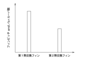
- the second heat exchange fins F2 have a different shape from the first heat exchange fins F1 so that the pressure loss of the refrigerant in the internal heat exchange section 15 is reduced.
- the second heat exchange fins F2 have at least one of the fin pitch, which is the distance between the top portions of the base material SU, and the number of louvers R, compared to the first heat exchange fins F1. It's getting smaller.
- the refrigeration cycle device 1 including the composite heat exchanger HEX configured as described above includes a control unit 100 for controlling various component devices.
- the control unit 100 is composed of a microcomputer including a processor and a memory, and its peripheral circuits.
- the control unit 100 performs various calculations and processes based on a control program stored in a memory.
- the memory of the control unit 100 is composed of a non-transitional physical storage medium.
- a compressor 11, a pressure reducing valve 16, etc. are connected to the output side of the control unit 100.
- a sensor group for air conditioning control and a sensor group for equipment temperature control are connected to the input side of the control unit 100.
- various operation switches are connected to the input side of the control unit 100, and operation signals of the various operation switches are inputted.
- Various operation switches include air conditioner switch, room temperature adjustment switch, etc.
- the air conditioner switch is a switch for setting whether or not the air conditioning unit 40 cools the air.
- the room temperature adjustment switch is a switch that sets a set temperature in the vehicle interior.
- the control unit 100 operates the refrigeration cycle device 1 based on sensor outputs from a sensor group for air conditioning control and a sensor group for equipment temperature control, operation signals from various operation switches, and the like. For example, the control unit 100 drives the compressor 11 and controls the pressure reducing valve 16 to a throttled state. For example, regarding the control signal output to the pressure reducing valve 16, the control unit 100 determines the degree of superheat on the refrigerant suction side of the compressor 11 to be a predetermined target degree of superheat.
- the high-pressure refrigerant discharged from the compressor 11 flows into the condensing section 12 of the composite heat exchanger HEX.
- the high-pressure refrigerant that has flowed into the condensing section 12 radiates heat to the high-temperature side heat medium flowing through the high-temperature side circuit 50 .
- the high-pressure refrigerant flowing through the condensing section 12 is cooled and condensed.
- the high-pressure refrigerant that flows into the condensing section 12 from one side in the stacking direction Dst flows through the condensing section 12 in a U-turn, and then passes through the supercooling section 14 and the internal heat exchange section 15 for high-pressure introduction. It flows into the liquid storage section 13 via the path HPi.
- the high-pressure refrigerant is separated into gas and liquid in the liquid storage part 13, and the surplus high-pressure liquid refrigerant in the cycle is stored inside the liquid storage part 13.
- the high-pressure liquid refrigerant stored in the liquid storage section 13 flows into the subcooling section 14 via a side flow path SP provided in the internal heat exchange section 15 and a high-pressure outlet path HPo that penetrates the internal heat exchange section 15 .
- the high-pressure liquid refrigerant that has flowed into the supercooling section 14 is supercooled by exchanging heat with the high temperature side heat medium.
- the high-pressure liquid refrigerant that has passed through the supercooling section 14 flows into the first heat exchange channel 151 of the internal heat exchange section 15 .
- the high-pressure liquid refrigerant that has flowed into the first heat exchange channel 151 of the internal heat exchange section 15 exchanges heat with the low-pressure refrigerant that has passed through the evaporator 17 in the internal heat exchange section 15 and is subcooled.
- the high-pressure liquid refrigerant that has passed through the first heat exchange channel 151 of the internal heat exchange section 15 is reduced in pressure by the pressure reduction valve 16.
- the low-pressure refrigerant that has passed through the evaporator 17 flows into the second heat exchange channel 152 of the internal heat exchange section 15 and absorbs heat from the high-pressure liquid refrigerant.
- the low-pressure refrigerant that has passed through the second heat exchange channel 152 of the internal heat exchange section 15 flows to the suction side of the compressor 11 and is compressed by the compressor 11 again.
- the composite heat exchanger HEX described above includes a condensing section 12, a liquid storage section 13, a subcooling section 14, and an internal heat exchange section 15.
- the portions 15 are connected by predetermined connecting elements to form an integral structure ST.
- the composite heat exchanger HEX configured as described above, the high-pressure liquid refrigerant stored in the liquid storage section 13 is supercooled by exchanging heat with the high-pressure side heat medium in the subcooling section 14, and then further internal heat exchange is performed. In section 15, heat is exchanged with a low-pressure refrigerant for supercooling. Therefore, the enthalpy of the high-pressure refrigerant can be sufficiently reduced in a single heat exchanger.
- the composite heat exchanger HEX of the present disclosure includes a condensing section 12, a subcooling section 14, and an internal heat exchange section 15 configured as an integrated structure ST. Therefore, the composite heat exchanger HEX capable of sufficiently reducing the enthalpy of high-pressure refrigerant can be realized in a compact manner.
- the liquid storage section 13 is arranged on the side of the structure ST. According to this, interference between the structure ST and the liquid storage section 13 is less likely to occur, and the degree of freedom in designing the liquid storage section 13 is increased. Therefore, sufficient gas-liquid separation performance of the high-pressure refrigerant in the liquid storage section 13 can be ensured.
- the composite heat exchanger HEX of this embodiment has the following features.
- the structure ST has a structure in which heat transfer between the condensing section 12 and the internal heat exchange section 15 is suppressed. According to this, unintended heat transfer between the condensing section 12 and the internal heat exchange section 15 is suppressed, so that the enthalpy of the high-pressure refrigerant can be sufficiently reduced in the internal heat exchange section 15.
- the supercooling section 14 is arranged between the condensing section 12 and the internal heat exchange section 15.
- the subcooling part 14 is interposed between the condensing part 12 and the internal heat exchange part 15, the condensing part 12 and the internal heat exchange part Unintended heat transfer between the two can be suppressed. That is, it is possible to realize a structure that suppresses unintended heat transfer between the condensing section 12 and the internal heat exchange section 15 in a compact manner.
- the heat exchange performance of the internal heat exchange section 15 is improved, and the enthalpy of the high-pressure refrigerant can be sufficiently reduced in the internal heat exchange section 15.
- the liquid storage section 13 is arranged adjacent to a portion of the structure ST that constitutes the internal heat exchange section 15.
- a high-pressure introduction path HPi for guiding the high-pressure refrigerant that has passed through the condensing section 12 to the liquid storage section 13 is formed in the structure ST so as to penetrate the supercooling section 14 and the internal heat exchange section 15.
- a high-pressure outlet path HPo for guiding the high-pressure liquid refrigerant stored in the liquid storage section 13 to the supercooling section 14 is formed in the structure ST so as to penetrate through the internal heat exchange section 15.
- a portion of the internal heat exchange section 15 adjacent to the liquid storage section 13 guides the high-pressure refrigerant flowing through the high-pressure introduction path HPi to the liquid storage section 13, and the high-pressure liquid stored in the liquid storage section 13. It has a structure that guides the refrigerant to the high pressure outlet path HPo.
- the high-pressure introduction path HPi that guides the high-pressure refrigerant that has passed through the condensing section 12 to the liquid storage section 13 and the high-pressure outlet path HPo that leads the high-pressure liquid refrigerant stored in the liquid storage section 13 to the supercooling section 14 are connected to the structure. It can be configured inside the ST. Therefore, the composite heat exchanger HEX in which the subcooling section 14 is disposed between the condensing section 12 and the internal heat exchange section 15 can be realized in a compact manner.
- the liquid storage section 13 is directly joined to a portion of the structure ST that constitutes the internal heat exchange section 15. In this way, by integrally configuring the liquid storage section 13 and the internal heat exchange section 15, the composite heat exchanger HEX can be realized in a compact manner.
- the condensing section 12, the supercooling section 14, and the internal heat exchange section 15 are constructed by stacking and joining a plurality of plate-like members 30. This makes it easier to realize the composite heat exchanger HEX with excellent heat exchange efficiency in a compact manner.
- the plurality of plate members 30 are formed with at least two high-temperature side passage holes HL1 for passing high-pressure refrigerant including high-pressure liquid refrigerant, and for passing high-temperature side heat medium or low-pressure refrigerant.
- the porous member includes at least one low-temperature side channel hole HL2 formed therein.
- the porous member is formed such that the flow path hole through which the high-pressure liquid refrigerant passes in the high temperature side flow path hole HL1 is adjacent to the low temperature side flow path hole HL2. According to this, it becomes easier to radiate heat from the high-pressure liquid refrigerant to the high-temperature side heat medium and the low-pressure refrigerant, so it becomes possible to sufficiently reduce the enthalpy of the high-pressure liquid refrigerant in the composite heat exchanger HEX. In other words, it is possible to suppress heat damage caused by unintended heat reception of the high-pressure liquid refrigerant.
- the porous member includes a large diameter hole as a high temperature side flow path hole HL1 through which a high pressure refrigerant in a gaseous state or a high pressure liquid refrigerant passes, and a hole with a smaller diameter than the large diameter hole through which a high pressure liquid refrigerant passes.
- a small diameter hole is formed at a position adjacent to the low temperature side flow path hole HL2.
- the plurality of plate-like members 30 are each provided with a sacrificial layer SL on one surface side, and are joined so that the one surfaces provided with the sacrificial layer SL are in contact with each other, and the plate-like members 30 are joined such that the sacrificial layer SL is not provided.
- the surfaces are joined so that they touch each other.
- a first heat exchange flow path 151 is formed through which the high-pressure liquid refrigerant that has passed through the cooling section 14 passes.
- a second condensing flow path 122 through which a high-temperature side heat medium passes
- a second subcooling flow path 142 through which a high-temperature side heat medium passes
- a second condensation flow path 142 through which a low-pressure refrigerant passes.
- a heat exchange channel 152 is formed.
- a flow path for passing the high-temperature heat medium and low-pressure refrigerant is formed between the surfaces on which the sacrificial layer SL is provided, and a flow path for passing the high-pressure refrigerant between the other surfaces on which the sacrificial layer SL is not provided.
- a flow path that allows the corrosion resistance to increase it is possible to ensure both corrosion resistance and pressure resistance.
- the configuration of the plate-like member 30 used in the internal heat exchange section 15 is changed from that of the plate member 30 used in the condensing section 12 and the supercooling section 14.
- the configuration can be made common to the configuration of the shaped member 30. This makes it easier to design a structure ST in which the condensing section 12, the supercooling section 14, and the internal heat exchange section 15 are integrated.
- the plurality of plate members 30 constituting each of the condensing section 12, the supercooling section 14, and the internal heat exchange section 15 are made of plate materials having at least the same thickness and outer dimensions. According to this, the configuration of the plate member 30 used in the internal heat exchange section 15 can be made common to the configuration of the plate member 30 used in the condensation section 12 and the supercooling section 14, and the condensation section 12, supercooling section 14, It becomes easier to design a structure ST in which the section 14 and the internal heat exchange section 15 are integrated.
- the condensing section 12 and the supercooling section 14 include first heat exchange fins F1 that promote heat exchange between the high-pressure refrigerant and the high-temperature side heat medium.
- the internal heat exchange section 15 includes second heat exchange fins F2 that promote heat exchange between the high-pressure liquid refrigerant and the low-pressure refrigerant.
- the second heat exchange fins F2 have a different shape from the first heat exchange fins F1 so that the pressure loss of the refrigerant in the internal heat exchange section 15 is reduced.
- the second heat exchange fins F2 included in the internal heat exchange section 15 have a shape that can suppress the pressure loss of the refrigerant in the internal heat exchange section 15, the heat exchange performance of the internal heat exchange section 15 can be improved.
- the pressure loss of the low-pressure refrigerant in the internal heat exchange section 15 can be suppressed while ensuring the same. Therefore, deterioration of the coefficient of performance COP of the refrigeration cycle 10 can be suppressed.
- the plate-like member 30 of the first embodiment has large-diameter holes formed at the four corners of the plate-like member 30 and small-diameter holes formed between the large-diameter holes, the present invention is not limited thereto.
- the plate-like member 30 may have, for example, a large-diameter hole and a small-diameter hole formed at the four corners of the plate-like member 30, and a large-diameter hole formed between the large-diameter hole and the small-diameter hole. In this case, it is desirable that the small diameter hole be formed at a position adjacent to the low temperature side flow path hole HL2.
- the liquid storage section 13 of this embodiment is configured not of a receiver tank RT but of a modulator tank MT in which a refrigerant inlet and outlet is provided below.
- the modulator tank MT is configured such that the high-pressure liquid refrigerant stored therein can flow out from the lower side.
- the liquid storage section 13 is arranged outside the structure ST.
- the liquid storage section 13 of this embodiment is arranged adjacent to a portion of the structure ST that constitutes the internal heat exchange section 15.
- the second communication hole 157 is formed in the upper part, and the third communication hole 158 is formed in the lower part. Therefore, it is not possible to directly connect the internal heat exchange section 15 to the modulator tank MT.
- a portion of the internal heat exchange section 15 adjacent to the liquid storage section 13 guides the high-pressure refrigerant flowing through the high-pressure introduction path HPi to the liquid storage section 13.
- the high-pressure liquid refrigerant stored in the refrigerant 13 is guided to the high-pressure outlet path HPo.
- the second end member 36 located at the other end in the stacking direction Dst is connected to the refrigerant inlet of the modulator tank MT.
- a communicating hole is formed.
- a side flow path SP is formed by the second end member 36 to guide the high-pressure liquid refrigerant that has passed through the second communication hole 157 to the communication hole.
- the modulator tank MT which is the liquid storage section 13 is integrally joined to the internal heat exchange section 15 by brazing. That is, the composite heat exchanger HEX is integrally constructed by connecting the condensing section 12, the liquid storage section 13, the subcooling section 14, and the internal heat exchange section 15 with a brazing material.
- the composite heat exchanger HEX of the present embodiment can obtain the same effects as the first embodiment from the same configuration or equivalent configuration as the first embodiment.
- the liquid storage section 13 is connected to a portion of the structure ST that constitutes the internal heat exchange section 15 via a tank connector CNt.
- the tank connector CNt is formed with an introduction hole for introducing high-pressure refrigerant into the liquid storage section 13 and a discharge hole for introducing the high-pressure liquid refrigerant from the liquid storage section 13.
- the tank connector CNt is connected to the second end member 36 of the internal heat exchange section 15 so as not to interfere with the low pressure inlet connector CLi and the low pressure outlet connector CLo.
- the liquid storage section 13 is configured such that the center position CT of the liquid storage section 13 does not overlap with the central plane CP along the direction in which the condensation section 12, supercooling section 14, and internal heat exchange section 15 in the structure ST are arranged. It is located. Specifically, the liquid storage section 13 is arranged such that the center position CT of the liquid storage section 13 is located on the opposite side of the low pressure introduction connector CLi and the low pressure output connector CLo with respect to the above-mentioned central plane CP. ing. Note that the direction in which the condensing section 12, the supercooling section 14, and the internal heat exchange section 15 are arranged is a direction that corresponds to the stacking direction Dst.
- the central plane CP is a plane formed by connecting the centers of a pair of outer surfaces of the internal heat exchanger 15 along the stacking direction Dst and the vertical direction Dg, respectively.
- the composite heat exchanger HEX of the present embodiment can obtain the same effects as the first embodiment from the same configuration or equivalent configuration as the first embodiment.
- the composite heat exchanger HEX of this embodiment has the following features.
- the liquid storage section 13 is arranged so that its center position CT does not overlap the center plane CP along the direction in which the condensing section 12, supercooling section 14, and internal heat exchange section 15 in the structure ST are arranged. has been done. According to this, the parts constituting the structure ST and the liquid storage section 13 are less likely to interfere with each other, making it easier to design the composite heat exchanger HEX.
- liquid storage section 13 of the third embodiment is connected to the structure ST via the tank connector CNt
- the present invention is not limited to this, and for example, as in the first embodiment, the liquid storage section 13 is directly connected to the internal heat exchange section 15. It may be joined to.
- the liquid storage section 13 may be connected to a portion of the structure ST on the other side in the stacking direction Dst by a refrigerant introduction pipe TBi and a refrigerant outlet pipe TBo.
- the side passage SP is omitted, the refrigerant introduction pipe TBi is connected to the second communication hole 157, and the refrigerant outlet pipe TBo is connected to the third communication hole 158. connected like this.
- the composite heat exchanger HEX of the present embodiment can obtain the same effects as the first embodiment from the same configuration or equivalent configuration as the first embodiment.
- the liquid storage section 13 of the fourth embodiment is connected to the other side of the structure ST in the stacking direction Dst by a refrigerant introduction pipe TBi and a refrigerant outlet pipe TBo, but is not limited thereto.
- the liquid storage section 13 is connected to the other side of the structure ST in the stacking direction Dst by a refrigerant introduction pipe TBi, and connected to one side of the structure ST in the stacking direction Dst by a refrigerant outlet pipe TBo. It may be connected to the side part.
- the internal heat exchange section 15 is spaced apart from one of the condensing section 12 and the supercooling section 14, and They are connected to each other via fastening parts.
- the structure ST has a structure in which heat transfer between the condensing section 12 and the internal heat exchange section 15 is suppressed.
- the supercooling section 14 is arranged between the condensing section 12 and the internal heat exchange section 15.
- the internal heat exchange section 15 is coupled to the supercooling section 14 by a first intermediate connector CNc1 and a second intermediate connector CNc2 that constitute fastening parts.
- the liquid storage section 13 is directly joined to a portion of the structure ST that constitutes the internal heat exchange section 15.
- the internal heat exchange section 15 is connected to the supercooling section 14 with a gap between the first intermediate connector CNc1 and the second intermediate connector CNc2.
- the internal heat exchange section 15 and the supercooling section 14 are separated from each other except for the portions connected to the first intermediate connector CNc1 and the second intermediate connector CNc2.
- the first intermediate connector CNc1 includes a connection flow path connecting the first communication hole 147 and the second communication hole 157 and a connection flow path connecting the second supercooling flow path 142 and the first heat exchange flow path 151.
- a road is formed.
- a connection flow path connecting the third communication hole 158 and the first supercooling flow path 141 is formed in the second intermediate connector CNc2.
- the composite heat exchanger HEX of the present embodiment can obtain the same effects as the first embodiment from the same configuration or equivalent configuration as the first embodiment.
- the composite heat exchanger HEX of this embodiment has the following features.
- the internal heat exchange section 15 is connected to one of the condensing section 12 and the subcooling section 14 via a fastening part, with a space between the internal heat exchange section 15 and one of the heat exchange sections. ing.
- one of the heat exchange parts of the condensing part 12 and the supercooling part 14 is coupled to the internal heat exchange part 15 with a gap between them, one of the heat exchange parts and the internal heat exchange part 15 Unintended heat transfer between the two can be suppressed. That is, it is possible to realize a structure that suppresses unintended heat transfer between one heat exchange section and the internal heat exchange section 15 in a compact manner. Thereby, the heat exchange performance of the internal heat exchange section 15 is improved, and it becomes possible to sufficiently reduce the enthalpy of the high-pressure refrigerant in the internal heat exchange section 15.
- the internal heat exchange part 15 is configured to be connected to one heat exchange part by a fastening part, by removing the internal heat exchange part 15, a heat exchanger without an internal heat exchange function can be obtained. be able to. According to this, it becomes easy to design the addition and deletion of internal heat exchange functions, and it becomes possible to easily increase the variations of the composite heat exchanger HEX.
- the internal heat exchange section 15 is connected to one heat exchange section using a fastening component, the internal heat exchange section 15 and one heat exchange section will be It is possible to alleviate the effects of thermal strain on the bonded parts.
- the supercooling section 14 is arranged between the condensing section 12 and the internal heat exchange section 15.
- the internal heat exchange section 15 is connected to the supercooling section 14 with a space therebetween. In this way, if the subcooling part 14 is interposed between the condensing part 12 and the internal heat exchange part 15, the condensing part 12 and the internal heat exchange part Unintended heat transfer between the two can be suppressed.
- the liquid storage section 13 is directly joined to a portion of the structure ST that constitutes the internal heat exchange section 15. In this way, by integrally configuring the liquid storage section 13 and the internal heat exchange section 15, the composite heat exchanger HEX can be realized in a compact manner.
- the internal heat exchange section 15 is connected to the condensing section 12 via a fastening component with a space provided therebetween.
- the structure ST has a structure in which heat transfer between the condensing section 12 and the internal heat exchange section 15 is suppressed.
- the condensing section 12 is arranged between the supercooling section 14 and the internal heat exchange section 15.
- the internal heat exchange section 15 is coupled to the condensing section 12 by a first intermediate connector CNc1 and a second intermediate connector CNc2 that constitute fastening parts.
- the liquid storage portion 13 is directly joined to a portion of the structure ST that constitutes the supercooled portion 14 .
- a first condensation hole 123 and a second condensation hole 124 are formed in the plurality of plate-like members 30 constituting the condensation section 12 to allow the high-pressure refrigerant to pass in the stacking direction Dst. Furthermore, first heat medium holes 125 and second heat medium holes 126 are formed in the plurality of plate members 30 constituting the condensing section 12 for allowing the high temperature side heat medium to pass in the stacking direction Dst. Furthermore, supercooling communication holes 127 are formed in the plurality of plate members 30 constituting the condensing section 12, through which the high-pressure liquid refrigerant that has passed through the supercooling section 14 passes.
- a first condensation hole 123 and a second condensation hole 124 are formed in two diagonal corners among the four corners of the plurality of plate members 30 constituting the condensation section 12, and the second condensation hole 124 is formed in the remaining two corners.
- a first heat medium hole 125 and a second heat medium hole 126 are formed. Specifically, the first condensation hole 123 and the second heat medium hole 126 are formed in the upper side of the plate-shaped member 30, and the second condensation hole 124, the first heat medium hole 125, and the supercooling communication hole 127 are formed in the plate-shaped member 30. It is formed on the lower side of the member 30.
- the supercooling communication hole 127 is formed between the second condensation hole 124 and the first heat medium hole 125.
- the supercooling communication hole 127 has a smaller diameter than the first condensation hole 123 and the second condensation hole 124.
- the first condensation hole 123, the second condensation hole 124, and the supercooling communication hole 127 constitute the high temperature side flow path hole HL1
- the first heat medium hole 125 and the second heat medium hole 126 constitute the low temperature side flow path hole HL1. It constitutes the passage hole HL2.
- the first condensation hole 123 and the second condensation hole 124 constitute a large diameter hole
- the supercooling communication hole 127 constitutes a small diameter hole.
- the second intermediate member 33 located in the middle in the stacking direction Dst has a second condensing hole 124, a first heat medium hole 125, and a second heat medium hole 126.
- the supercooling communication hole 127 is formed, and the first condensation hole 123 is not formed.
- the high-pressure refrigerant flow path in the condensing section 12 becomes a U-turn flow path.
- the first end member 31 located at the other end in the stacking direction Dst is provided with a first intermediate connector CNc1 and a second intermediate connector CNc2.
- the first intermediate connector CNc1 and the second intermediate connector CNc2 also function as connectors that introduce high-pressure refrigerant and introduce and extract high-temperature side heat medium.
- the upstream flow path for high-pressure refrigerant is a downflow flow path
- the downstream flow path for high-pressure refrigerant is an upflow flow path
- the flow path of the high temperature side heat medium in the condensing section 12 is an upflow flow path.
- the plurality of plate-like members 30 constituting the supercooling section 14 have first supercooling holes 143 and second supercooling holes 144 formed therein. Further, third heat medium holes 145 and fourth heat medium holes 146 are formed in the plurality of plate-shaped members 30 constituting the supercooling section 14 in order to allow the high temperature side heat medium to pass in the stacking direction Dst. has been done. Furthermore, first communication holes 147 are formed in the plurality of plate-like members 30 constituting the subcooling section 14 to form a high-pressure introduction path HPi for guiding the high-pressure refrigerant that has passed through the condensing section 12 to the liquid storage section 13. ing.
- a third heat medium hole 145 and a fourth heat medium hole 146 are formed in two diagonally located corners among the four corners of the plurality of plate members 30 constituting the supercooling section 14, and the remaining two A first communication hole 147 is formed in one of the corners. Further, the first supercooling hole 143 is formed between the first communication hole 147 and the fourth heat medium hole 146. The second supercooling hole 144 is formed at a position adjacent to the third heat medium hole 145. Specifically, the first supercooling hole 143, the fourth heat medium hole 146, and the first communication hole 147 are formed on the upper side of the plate member 30, and the second supercooling hole 144 and the third heat medium hole 145 are formed on the upper side of the plate member 30. It is formed on the lower side of the plate member 30.
- the third heat medium hole 145 is formed at a position overlapping with the first heat medium hole 125 in the stacking direction Dst so as to communicate with the first heat medium hole 125.
- the fourth heat medium hole 146 is formed at a position overlapping with the second heat medium hole 126 in the stacking direction Dst so as to communicate with the second heat medium hole 126.
- the second subcooling hole 144 is formed at a position overlapping with the subcooling communication hole 127 in the stacking direction Dst so as to communicate with the subcooling communication hole 127.
- the first supercooling hole 143, the second supercooling hole 144, and the first communication hole 147 constitute the high temperature side flow path hole HL1
- the third heat medium hole 145 and the fourth heat medium hole 146 constitute the low temperature side flow path hole HL1. It constitutes a side passage hole HL2.
- the first communication hole 147 constitutes a large diameter hole
- the first supercooling hole 143 and the second supercooling hole 144 constitute a small diameter hole.
- the high-pressure liquid refrigerant flow path is a downflow flow path
- the high temperature side heat medium flow path is an upflow flow path.
- the plurality of plate-like members 30 constituting the internal heat exchange section 15 have first heat exchange holes 153 and second heat exchange holes 154 for passing the high-pressure liquid refrigerant that has passed through the subcooling section 14 in the stacking direction Dst. It is formed. Furthermore, first low pressure holes 155 and second low pressure holes 156 are formed in the plurality of plate members 30 constituting the internal heat exchange section 15 for allowing the low pressure refrigerant to pass in the stacking direction Dst.
- First heat exchange holes 153 and second heat exchange holes 154 are formed at two diagonal corners among the four corners of the plurality of plate members 30 constituting the internal heat exchange section 15, and the remaining two A first low pressure hole 155 and a second low pressure hole 156 are formed at each corner.
- the second heat exchange hole 154 and the first low pressure hole 155 are formed on the upper side of the plate-like member 30, and the first heat exchange hole 153 and the second low-pressure hole 156 are formed on the lower side of the plate-like member 30. It is formed.
- the second end member 36 located at the other end in the stacking direction Dst has a low pressure hole communicating with the first low pressure hole 155.
- a low voltage outlet connector CLo communicating with the introduction connector CLi and the second low pressure hole 156 is connected.
- the high-pressure liquid refrigerant flow path is an upflow flow path
- the low-pressure refrigerant flow path is a downflow flow path.
- the receiver tank RT which is the liquid storage section 13 is arranged adjacent to a portion that constitutes the supercooling section 14.
- a first supercooling hole 143 and a first communication hole 147 are formed on the upper side of the plate member 30 . Therefore, the receiver tank RT can be connected to the supercooling section 14 without providing the side flow path SP described in the first embodiment.
- the composite heat exchanger HEX of the present embodiment can obtain the same effects as the first embodiment from the same configuration or equivalent configuration as the first embodiment.
- the composite heat exchanger HEX of this embodiment has the following features.
- the condensing section 12 is arranged between the supercooling section 14 and the internal heat exchange section 15.
- the internal heat exchange section 15 is connected to the condensing section 12 with a space therebetween. In this way, if the condensing section 12 and the internal heat exchange section 15 are coupled with a space between them, the connection between the condensing section 12 and the internal heat exchange section 15 can be made without adding separate parts such as a heat insulating material. It is possible to suppress unintended heat transfer.
- the liquid storage portion 13 is directly joined to a portion of the structure ST that constitutes the supercooling portion 14. In this way, by configuring the liquid storage section 13 and the supercooling section 14 integrally, the composite heat exchanger HEX can be realized in a compact manner.
- the liquid storage section 13 is connected to a portion of the structure ST that constitutes the supercooling section 14 via a connector CNs.
- the liquid storage part 13 may be joined directly to the site
- a condensing section 12 is arranged between an internal heat exchange section 15 and a supercooling section 14, and an evaporator 17 is connected to the internal heat exchange section 15 via a connector. is connected.
- the evaporator 17 is connected to the other end of the internal heat exchange section 15 in the stacking direction Dst via the first connection connector CNe1 and the second connection connector CNe2.
- the first connecting connector CNe1 and the second connecting connector CNe2 are connectors that connect the internal heat exchange section 15 and the evaporator 17.
- the first connection connector CNe1 also functions as a connector for introducing low-pressure refrigerant from the evaporator 17 to the internal heat exchange section 15.
- a pressure reducing valve 16 that reduces the pressure of the high-pressure liquid refrigerant that has passed through the internal heat exchange section 15 is integrally formed in the first connection connector CNe1.
- the second connection connector CNe2 may be omitted since there is no flow path for circulating the refrigerant.
- a first evaporation channel 171 and a second evaporation channel 172 are formed by joining a plurality of plate-like members 30 in a stacked state.
- the first evaporation channels 171 and the second evaporation channels 172 are arranged alternately one by one.
- a first evaporation hole 173 and a second evaporation hole 174 are formed in the plurality of plate-like members 30 constituting the evaporator 17 to allow the low-pressure refrigerant to pass in the stacking direction Dst. Further, first low temperature holes 175 and second low temperature holes 176 are formed in the plurality of plate members 30 constituting the evaporator 17 for allowing the low temperature side heat medium to pass in the stacking direction Dst.
- a first evaporation hole 173 and a second evaporation hole 174 are formed in two diagonally located corners among the four corners of the plurality of plate members 30 constituting the evaporator 17, and the second evaporation hole 174 is formed in the remaining two corners.
- a first cold hole 175 and a second cold hole 176 are formed. Specifically, the first evaporation hole 173 and the first low temperature hole 175 are formed on the upper side of the plate-like member 30, and the second evaporation hole 174 and the second low-temperature hole 176 are formed on the lower side of the plate-like member 30. ing.
- the other end member 37 located at the other end in the stacking direction Dst is provided with a first cold hole 175 and a second cold hole 176. Evaporation holes 173 and second evaporation holes 174 are not provided.
- one end member 38 located at one end in the stacking direction Dst is provided with a first evaporation hole 173 and a second evaporation hole 174, and a first low temperature Hole 175 and second cold hole 176 are not provided.
- the one end member 38 is formed with an evaporation communication hole 177 that communicates with the first low-pressure hole 155 of the internal heat exchange section 15.
- a guide channel GP is formed in the evaporator 17 adjacent to the one end member 38 to guide the refrigerant that has passed through the second evaporation hole 174 to the evaporation communication hole 177.
- both the low-pressure refrigerant flow path and the low-temperature side heat medium flow path are downflow flow paths. Thereby, in the evaporator 17, the low-pressure refrigerant and the low-temperature side heat medium flow in parallel.
- the composite heat exchanger HEX of this embodiment can obtain the same effects as the sixth embodiment from the same configuration or equivalent configuration as the sixth embodiment.
- the composite heat exchanger HEX of this embodiment has the following features.
- the evaporator 17 is connected to the internal heat exchange section 15 via the first connection connector CNe1 and the second connection connector CNe2. According to this, the condensing section 12, the supercooling section 14, the internal heat exchange section 15, and the evaporator 17 can be configured with a single heat exchanger. As a result, it becomes easier to reduce the cost of the refrigeration cycle 10 and realize the refrigeration cycle 10 in a compact manner by reducing the number of parts.
- either the vertical or horizontal dimension in front of the internal heat exchange section 15 is the larger of the vertical or horizontal dimension in front of the condensing section 12 and the subcooling section 14. It is smaller than.
- the front surface is a surface connecting the top surface and the bottom surface, and is a surface along the direction in which the condensing section 12, the supercooling section 14, and the internal heat exchange section 15 are arranged.
- the vertical direction Dg is vertical, and the direction in which the condensing section 12, the supercooling section 14, and the internal heat exchange section 15 are arranged (that is, the horizontal direction) is horizontal.
- the vertical dimension Lv is a dimension in the vertical direction Dg.
- the lateral dimension Lh is a dimension in the horizontal direction.
- the horizontal dimension Lhc at the front is larger than the vertical dimension Lvc.
- the supercooled section 14 has a vertical dimension Lvs larger than a horizontal dimension Lhs in the front.
- the vertical dimension Lvc of the condensing section 12 and the vertical dimension Lvs of the supercooling section 14 are approximately equal.
- the internal heat exchange section 15 has a vertical dimension Lvi larger than a lateral dimension Lhi at the front.
- the vertical dimension Lvi of the internal heat exchange section 15 is smaller than the vertical dimension Lvc of the condensing section 12 and the vertical dimension Lvs of the supercooling section 14.
- the horizontal dimension Lhi of the internal heat exchange section 15 is smaller than the vertical dimension Lvc of the condensing section 12 and the vertical dimension Lvs of the supercooling section 14.
- the depth dimension of the internal heat exchange section 15 is approximately equal to the depth dimension of the condensing section 12 and the depth dimension of the subcooling section 14.
- the vertical dimension Lvi of the internal heat exchange section 15 is such that the internal heat exchange section 15 can be arranged between the first connection connector CNe1 and the second connection connector CNe2.
- the distance is less than or equal to the distance between the first connecting connector CNe1 and the second connecting connector CNe2.
- the composite heat exchanger HEX is configured such that the internal heat exchanger 15 is arranged such that the first connecting connector CNe1 and the first intermediate connector CNc1 are close to each other, and the second connecting connector CNe2 and the second intermediate connector CNc2 are close to each other.
- a lateral dimension Lhi is set. Note that each of the connecting connectors CNe1 and CNe2 may be in contact with each of the intermediate connectors CNc1 and CNc2, or may be separate from each other.
- the plurality of plate-like members 30 constituting the internal heat exchange section 15 and the plurality of plate-like members 30 constituting the condensing section 12 and the supercooling section 14 are composed of plate materials having at least different external dimensions.
- the composite heat exchanger HEX of this embodiment can obtain the same effects as the seventh embodiment from the common configuration or equivalent configuration.
- the composite heat exchanger HEX of this embodiment has the following features.
- one of the vertical and horizontal dimensions at the front is smaller than the larger of the vertical and horizontal dimensions at the front of the condensing section 12 and the supercooling section 14. In this way, by configuring the internal heat exchange section 15 in a small size, it becomes easier to realize the composite heat exchanger HEX in a compact manner. Further, pressure loss in the internal heat exchange section 15 can be suppressed, and deterioration of the coefficient of performance COP of the refrigeration cycle 10 can be suppressed.
- the larger of the vertical and horizontal dimensions at the front is smaller than the larger of the vertical and horizontal dimensions of the condensing section 12 and the supercooling section 14. ing. According to this, it is possible to make the composite heat exchanger HEX compact, suppress pressure loss in the internal heat exchange section 15, and improve the coefficient of performance COP of the refrigeration cycle 10.
- the composite heat exchanger HEX of the eighth embodiment has the evaporator 17 connected to the internal heat exchange section 15, the structure is not limited to this, and the structure is such that the evaporator 17 is not connected to the internal heat exchange section 15. It may be.
- the vertical dimension Lvc of the condensing section 12 and the vertical dimension Lvs of the supercooling section 14 are approximately equal.
- the vertical dimension Lvi and the horizontal dimension Lhi of the internal heat exchange section 15 are smaller than the vertical dimension Lvc of the condensing section 12 and the vertical dimension Lvs of the supercooling section 14.
- the depth Lwc of the condensing section 12 and the depth Lws of the supercooling section 14 are approximately equal.
- the depth Lwi of the internal heat exchange section 15 is smaller than the depth Lwc of the condensing section 12 and the depth Lws of the supercooling section 14.
- the composite heat exchanger HEX of this embodiment can obtain the same effects as the eighth embodiment from the same configuration or equivalent configuration as the eighth embodiment.
- the composite heat exchanger HEX of this embodiment has the following features.
- the internal heat exchange section 15 has a larger depth than the condensing section 12 and the supercooling section 14. According to this, it is possible to secure the heat exchange area between the high pressure liquid refrigerant and the low pressure refrigerant in the internal heat exchange section 15, so that the performance of the internal heat exchange section 15 can be secured and the composite heat exchanger HEX can be made more compact. It becomes possible to aim for.
- a first three-way valve 18 that branches the flow of refrigerant is arranged between the first heat exchange channel 151 of the internal heat exchange section 15 and the pressure reducing valve 16.
- the first three-way valve 18 has one refrigerant inlet and two refrigerant outlets.
- a first heat exchange channel 151 of the internal heat exchange section 15 is connected to the refrigerant inlet side of the first three-way valve 18 .
- a pressure reducing valve 16 is connected to one refrigerant outlet side of the first three-way valve 18 .
- An air conditioning pressure reducing valve 19 is connected to the other refrigerant outlet side of the first three-way valve 18 .
- the air conditioning pressure reducing valve 19 is a pressure reducing section that reduces the pressure of the high-pressure liquid refrigerant that has passed through the internal heat exchange section 15.
- the air conditioning pressure reducing valve 19 is an electric variable throttle whose operation is controlled by a control signal output from the control unit 100, and includes a valve body and an electric actuator.
- An air conditioning evaporator 20 is connected to the refrigerant outlet side of the air conditioning pressure reducing valve 19.
- the air conditioning evaporator 20 is a heat absorber that evaporates the low-pressure refrigerant whose pressure has been reduced by the air conditioning pressure reducing valve 19 by exchanging heat with the air blown into the vehicle interior.
- the air conditioning evaporator 20 has a first evaporation channel 171 through which the low-pressure refrigerant whose pressure has been reduced by the pressure reducing valve 16 passes, and a second evaporation channel 172 through which the low-temperature side heat medium passes.
- the air conditioning evaporator 20 is comprised of a fin-and-tube type heat exchanger.
- An evaporation pressure regulating valve 21 is connected to the refrigerant outlet side of the air conditioning evaporator 20.
- the evaporation pressure regulating valve 21 is a regulating valve that regulates the pressure on the refrigerant outlet side of the air conditioning evaporator 20 to be equal to or higher than a predetermined pressure.
- a second three-way valve 22 is arranged on the refrigerant outlet side of the evaporation pressure adjustment valve 21 to allow the low-pressure refrigerant that has passed through the evaporation pressure adjustment valve 21 and the low-pressure refrigerant that has passed through the evaporator 17 to join together.
- the second three-way valve 22 has two refrigerant inlets and one refrigerant outlet.
- An evaporation pressure regulating valve 21 is connected to one refrigerant inlet side of the second three-way valve 22 .
- the evaporator 17 is connected to the other refrigerant inlet side of the second three-way valve 22 .
- the compressor 11 is connected to the refrigerant outlet side of the second three-way valve 22 .
- the low-pressure refrigerant that has passed through the evaporation pressure regulating valve 21 and the low-pressure refrigerant that has passed through the evaporator 17 are sucked into the compressor 11 and then compressed again.
- the condensing section 12, liquid storage section 13, subcooling section 14, internal heat exchange section 15, pressure reducing valve 16, and evaporator 17 are of a composite type. Integrated as heat exchanger HEX.
- the composite heat exchanger HEX will be described below with reference to FIG. 22.
- the composite heat exchanger HEX has a configuration similar to that of the seventh embodiment, including a condensing section 12, a liquid storage section 13, a subcooling section 14, an internal heat exchange section 15, a pressure reducing valve 16, An evaporator 17 is integrated.
- the composite heat exchanger HEX of this embodiment is different from that described in the seventh embodiment in the structure of the internal heat exchange section 15, the structure of the evaporator 17, and the like.
- a first heat exchange hole 153, a second heat exchange hole 154, a first low pressure hole 155, and a second low pressure hole 156 are formed in the plurality of plate members 30 constituting the internal heat exchange section 15.
- a second heat exchange hole 154 and a first low pressure hole 155 are formed on the upper side of the plate-like member 30, and a first heat exchange hole 153 and a second low-pressure hole 156 are formed on the lower side of the plate-like member 30.
- the first heat exchange hole 153 and the second heat exchange hole 154 are tanks that distribute high pressure liquid refrigerant to the first heat exchange flow path 151 or collect the high pressure liquid refrigerant that has passed through the first heat exchange flow path 151. form a space.
- the internal member 39 located in the middle in the stacking direction Dst has a second heat exchange hole 154, a first low pressure hole 155, and a second low pressure hole 156.
- the first heat exchange hole 153 is not formed. Thereby, the flow path of the high-pressure liquid refrigerant in the internal heat exchange section 15 becomes a U-turn flow path.
- the upstream flow path for the high-pressure liquid refrigerant is an upflow flow path
- the downstream flow path for the high-pressure liquid refrigerant is a downflow flow path
- the flow path of the low-pressure refrigerant in the internal heat exchange section 15 is a downflow flow path.
- the evaporator 17 is connected to the other end in the stacking direction Dst via the first connection connector CNe1 and the second connection connector CNe2.
- the first connecting connector CNe1 and the second connecting connector CNe2 are connectors that connect the internal heat exchange section 15 and the evaporator 17.
- the first connection connector CNe1 also functions as a connector for introducing low-pressure refrigerant from the evaporator 17 to the internal heat exchange section 15.
- the first connecting connector CNe1 is configured to function as the second three-way valve 22.
- an evaporation pressure regulating valve 21 is integrally formed with the first connection connector CNe1.
- a pressure reducing valve 16 that reduces the pressure of the high-pressure liquid refrigerant that has passed through the internal heat exchange section 15 is integrally formed in the second connection connector CNe2. As a result, the low-pressure refrigerant whose pressure has been reduced by the pressure reducing valve 16 flows into the evaporator 17 .
- a first evaporation hole 173, a second evaporation hole 174, a first low temperature hole 175, and a second low temperature hole 176 are formed in the plurality of plate members 30 constituting the evaporator 17.
- a second evaporation hole 174 and a first low temperature hole 175 are formed on the upper side of the plate-like member 30, and a first evaporation hole 173 and a second low-temperature hole 176 are formed on the lower side of the plate-like member 30.
- the low-pressure refrigerant flow path is an upflow flow path
- the low-temperature side heat medium flow path is a downflow flow path.
- the composite heat exchanger HEX of this embodiment can obtain the same effects as the seventh embodiment from the common configuration or equivalent configuration.
- a branching part BR that branches the flow of refrigerant is arranged between the first condensing channel 121 of the condensing part 12 and the liquid storage part 13. Thereby, the refrigerant that has passed through the condensing section 12 is distributed to the liquid storage section 13 and the air conditioning pressure reducing valve 19.
- the condensing section 12, liquid storage section 13, subcooling section 14, and internal heat exchange section 15 are integrated as a composite heat exchanger HEX. There is.
- the composite heat exchanger HEX will be described below with reference to FIG. 24.
- the condensing section 12, supercooling section 14, and internal heat exchange section 15 are configured as an integrated structure ST by being connected by a predetermined connecting element.
- the condensing section 12 is provided with a branch connector CHd for flowing a part of the refrigerant that has passed through the condensing section 12 to the air conditioning pressure reducing valve 19.
- This branch connector CHd is provided at the other end of the condensing section 12 in the stacking direction Dst.
- some of the heat exchange sections have either vertical or horizontal dimensions at the front. It is smaller than the maximum vertical and horizontal dimensions at the front of the other heat exchange parts.
- the vertical dimension Lvc at the front of the condensing section 12 is the largest dimension.
- the vertical dimension Lvs of the supercooling section 14 at the front thereof is smaller than the vertical dimension Lvc of the condensing section 12.
- the vertical dimension Lvi of the internal heat exchange section 15 at the front thereof is approximately the same as the vertical dimension Lvs of the supercooling section 14 and smaller than the vertical dimension Lvc of the condensing section 12 .
- the vertical dimension Lvs of the supercooling section 14 and the vertical dimension Lvi of the internal heat exchange section 15 are smaller than the vertical dimension Lvc of the condensing section 12, so that the supercooling section 14 and the branch connector CHd are configured so as not to interfere with each other.
- the composite heat exchanger HEX can be realized in a compact manner.
- the composite heat exchanger HEX of the present embodiment can obtain the same effects as the first embodiment from the same configuration or equivalent configuration as the first embodiment.
- a branch section BR that branches the flow of refrigerant is arranged between the subcooling section 14 and the internal heat exchange section 15. Thereby, the refrigerant that has passed through the subcooling section 14 is distributed to the internal heat exchange section 15 and the air conditioning pressure reducing valve 19.
- the condensing section 12, liquid storage section 13, subcooling section 14, and internal heat exchange section 15 are integrated as a composite heat exchanger HEX. There is.
- the composite heat exchanger HEX will be described below with reference to FIG. 26.
- the condensing section 12, the supercooling section 14, and the internal heat exchange section 15 are configured as an integrated structure ST by being connected by a predetermined connecting element.
- the supercooling section 14 is provided with a branch connector CHd for causing a part of the refrigerant that has passed through the supercooling section 14 to flow to the air conditioning pressure reducing valve 19 .
- This branch connector CHd is provided at the other end of the supercooling section 14 in the stacking direction Dst.
- the vertical dimension Lvc at the front of the condensing section 12 and the vertical dimension at the front of the supercooling section 14 Lvs has the largest dimension.
- the vertical dimension Lvi at the front thereof is smaller than the vertical dimension Lvc of the condensing section 12 and the vertical dimension Lvs of the supercooling section 14.
- the vertical dimension Lvi of the internal heat exchange section 15 is smaller than the vertical dimension Lvc of the condensing section 12 and the vertical dimension Lv of the subcooling section 14, so that the internal heat exchanger The upper part of the portion 15 and the branch connector CHd are configured not to interfere with each other. With such a configuration, the composite heat exchanger HEX can be realized in a compact manner.
- the composite heat exchanger HEX of the present embodiment can obtain the same effects as the first embodiment from the same configuration or equivalent configuration as the first embodiment.
- either the vertical or horizontal dimension in front of the condensing section 12 is larger than the maximum dimension of the vertical or horizontal dimension in the front of the supercooling section 14 and the internal heat exchange section 15. It may be smaller.
- the composite heat exchanger HEX may include an evaporator 17 in addition to the condensing section 12, the supercooling section 14, and the internal heat exchange section 15.
- the composite heat exchanger HEX is provided with a flow path box BX for flowing the refrigerant in the order of the condensing section 12, the liquid storage section 13, the subcooling section 14, and the internal heat exchange section 15. .
- the flow path box BX can be realized by forming flow path holes in a metal block, for example, instead of using refrigerant piping.
- the flow path box BX is arranged on the side surface of the composite heat exchanger HEX. Note that the flow path box BX may be arranged on the top surface or the bottom surface of the composite heat exchanger HEX.
- the composite heat exchanger HEX of the present embodiment can obtain the same effects as the first embodiment from the same configuration or equivalent configuration as the first embodiment.
- the flow path box BX is connected to the structure ST in which the subcooling section 14 is arranged between the condensing section 12 and the internal heat exchange section 15, but the composite heat exchanger HEX is It is not limited to this.
- the composite heat exchanger HEX has a structure in which a flow path box BX is connected to a structure ST in which a condensing section 12 is arranged between a subcooling section 14 and an internal heat exchange section 15. Good too.
- the composite heat exchanger HEX has a structure in which the flow path box BX is connected to the structure ST including the condensing section 12, the subcooling section 14, the internal heat exchange section 15, and the evaporator 17, good.
- the plurality of plate members 30 constituting the condensing section 12, the supercooling section 14, and the internal heat exchange section 15 have at least the same thickness and external dimensions. Although it is made up of a board made of wood, it is not limited to this. For example, at least a portion of the plurality of plate-like members 30 constituting the condensing section 12, the supercooling section 14, and the internal heat exchange section 15 may be composed of plate materials having different thicknesses or external dimensions. Further, the internal heat exchange section 15 may be configured by stacking and joining a plurality of plate-like members 30 on which the sacrificial layer SL is not provided.
- the second heat exchange fins F2 have a different shape from the first heat exchange fins F1 so that the pressure loss of the refrigerant in the internal heat exchange section 15 is reduced, but the shape is not limited thereto.
- the first heat exchange fins F1 and the second heat exchange fins F2 may have the same shape.
- the structure ST has a structure that suppresses heat transfer between the condensing section 12 and the internal heat exchange section 15, but the present invention is not limited thereto.
- the condensing part 12 and the internal heat exchange part 15 may be directly joined to each other so that heat transfer occurs between the condensing part 12 and the internal heat exchange part 15.
- the structure ST may have an internal heat exchange section 15 disposed between the condensing section 12 and the supercooling section 14.
- the evaporator 17 is integrated with the structure ST in which the condensing section 12 is arranged between the internal heat exchange section 15 and the subcooling section 14.
- the evaporator 17 may be configured integrally with the structure ST in which the subcooling section 14 is arranged between the condensing section 12 and the internal heat exchange section 15. .
- the above-described composite heat exchanger HEX is configured as a plate-stacked heat exchanger in which the condensing section 12, supercooling section 14, and internal heat exchange section 15 are formed by stacking a plurality of plate members 30.
- the composite heat exchanger HEX may be configured, for example, as a shell-and-tube heat exchanger having a shell and a large number of heat exchanger tubes.
- the condensing section 12, the subcooling section 14, and the internal heat exchange section 15 may be connected to each other via a connector.
- the composite heat exchanger HEX of the above-described embodiment has the condensing section 12, the subcooling section 14, and the internal heat exchange section 15 arranged in a line along a predetermined direction
- the present invention is not limited thereto.
- the composite heat exchanger HEX even if one of the heat exchange parts of the condensing part 12, the supercooling part 14, and the internal heat exchange part 15 is arranged face-to-face with another heat exchange part, good.
- the liquid storage section 13 is desirably arranged so that the center position CT of the liquid storage section 13 does not overlap the central plane CP of the structure ST, but the present invention is not limited thereto.
- the liquid storage portion 13 may be arranged such that the center position CT of the liquid storage portion 13 overlaps the center plane CP of the structure ST.
- the composite heat exchanger HEX is applied to the refrigeration cycle device 1 for a vehicle, but the composite heat exchanger HEX is not limited to a system for a mobile object, It is also applicable to other systems or portable systems.
- the cycle configuration of the refrigeration cycle 10 and the device configuration of the refrigeration cycle device 1 to which the composite heat exchanger HEX is applied may be different from those described above.
Landscapes
- Engineering & Computer Science (AREA)
- Physics & Mathematics (AREA)
- Mechanical Engineering (AREA)
- Thermal Sciences (AREA)
- General Engineering & Computer Science (AREA)
- Heat-Exchange Devices With Radiators And Conduit Assemblies (AREA)
- Details Of Heat-Exchange And Heat-Transfer (AREA)
Priority Applications (3)
| Application Number | Priority Date | Filing Date | Title |
|---|---|---|---|
| CN202380028736.7A CN118900979A (zh) | 2022-03-23 | 2023-03-17 | 复合型热交换器 |
| DE112023001517.1T DE112023001517T5 (de) | 2022-03-23 | 2023-03-17 | Verbundwärmetauscher |
| US18/886,515 US20250012518A1 (en) | 2022-03-23 | 2024-09-16 | Composite heat exchanger |
Applications Claiming Priority (2)
| Application Number | Priority Date | Filing Date | Title |
|---|---|---|---|
| JP2022047473A JP7826778B2 (ja) | 2022-03-23 | 2022-03-23 | 複合型熱交換器 |
| JP2022-047473 | 2022-03-23 |
Related Child Applications (1)
| Application Number | Title | Priority Date | Filing Date |
|---|---|---|---|
| US18/886,515 Continuation US20250012518A1 (en) | 2022-03-23 | 2024-09-16 | Composite heat exchanger |
Publications (1)
| Publication Number | Publication Date |
|---|---|
| WO2023182219A1 true WO2023182219A1 (ja) | 2023-09-28 |
Family
ID=88100948
Family Applications (1)
| Application Number | Title | Priority Date | Filing Date |
|---|---|---|---|
| PCT/JP2023/010646 Ceased WO2023182219A1 (ja) | 2022-03-23 | 2023-03-17 | 複合型熱交換器 |
Country Status (5)
| Country | Link |
|---|---|
| US (1) | US20250012518A1 (https=) |
| JP (1) | JP7826778B2 (https=) |
| CN (1) | CN118900979A (https=) |
| DE (1) | DE112023001517T5 (https=) |
| WO (1) | WO2023182219A1 (https=) |
Families Citing this family (2)
| Publication number | Priority date | Publication date | Assignee | Title |
|---|---|---|---|---|
| JP2025161166A (ja) * | 2024-04-11 | 2025-10-24 | 株式会社デンソー | 熱交換器および減圧器 |
| WO2026053608A1 (ja) * | 2024-09-05 | 2026-03-12 | 株式会社デンソー | ヒートポンプ機能集合体、およびヒートポンプモジュール |
Citations (6)
| Publication number | Priority date | Publication date | Assignee | Title |
|---|---|---|---|---|
| JP2002228299A (ja) * | 2001-02-05 | 2002-08-14 | Showa Denko Kk | 複合型熱交換器 |
| JP2004190875A (ja) * | 2002-12-06 | 2004-07-08 | Denso Corp | 冷凍サイクル装置 |
| JP2005249376A (ja) * | 2004-02-03 | 2005-09-15 | Showa Denko Kk | 熱交換器および一体型熱交換器 |
| JP2016003828A (ja) * | 2014-06-18 | 2016-01-12 | 株式会社デンソー | 冷凍サイクル装置 |
| JP2020076566A (ja) * | 2018-11-02 | 2020-05-21 | 株式会社デンソー | 冷凍サイクル装置 |
| WO2021100409A1 (ja) * | 2019-11-22 | 2021-05-27 | 株式会社デンソー | 冷凍サイクル装置 |
Family Cites Families (2)
| Publication number | Priority date | Publication date | Assignee | Title |
|---|---|---|---|---|
| JP2008163828A (ja) | 2006-12-28 | 2008-07-17 | Suzuki Motor Corp | 筒内直接噴射エンジンの燃料噴射装置 |
| CN114173465A (zh) | 2020-09-11 | 2022-03-11 | 天材创新材料科技(厦门)有限公司 | 堆叠结构及触控感测器 |
-
2022
- 2022-03-23 JP JP2022047473A patent/JP7826778B2/ja active Active
-
2023
- 2023-03-17 CN CN202380028736.7A patent/CN118900979A/zh active Pending
- 2023-03-17 DE DE112023001517.1T patent/DE112023001517T5/de active Pending
- 2023-03-17 WO PCT/JP2023/010646 patent/WO2023182219A1/ja not_active Ceased
-
2024
- 2024-09-16 US US18/886,515 patent/US20250012518A1/en active Pending
Patent Citations (6)
| Publication number | Priority date | Publication date | Assignee | Title |
|---|---|---|---|---|
| JP2002228299A (ja) * | 2001-02-05 | 2002-08-14 | Showa Denko Kk | 複合型熱交換器 |
| JP2004190875A (ja) * | 2002-12-06 | 2004-07-08 | Denso Corp | 冷凍サイクル装置 |
| JP2005249376A (ja) * | 2004-02-03 | 2005-09-15 | Showa Denko Kk | 熱交換器および一体型熱交換器 |
| JP2016003828A (ja) * | 2014-06-18 | 2016-01-12 | 株式会社デンソー | 冷凍サイクル装置 |
| JP2020076566A (ja) * | 2018-11-02 | 2020-05-21 | 株式会社デンソー | 冷凍サイクル装置 |
| WO2021100409A1 (ja) * | 2019-11-22 | 2021-05-27 | 株式会社デンソー | 冷凍サイクル装置 |
Also Published As
| Publication number | Publication date |
|---|---|
| US20250012518A1 (en) | 2025-01-09 |
| JP2023141253A (ja) | 2023-10-05 |
| CN118900979A (zh) | 2024-11-05 |
| DE112023001517T5 (de) | 2025-02-13 |
| JP7826778B2 (ja) | 2026-03-10 |
Similar Documents
| Publication | Publication Date | Title |
|---|---|---|
| US8099978B2 (en) | Evaporator unit | |
| US20250012518A1 (en) | Composite heat exchanger | |
| CN114110816B (zh) | 换热器、电控盒以及空调系统 | |
| KR20140002774A (ko) | 열교환기 | |
| US20110056667A1 (en) | Integrated multi-circuit microchannel heat exchanger | |
| WO2014132602A1 (ja) | 積層型熱交換器 | |
| JP6497262B2 (ja) | 積層型熱交換器 | |
| JP7278430B2 (ja) | 熱交換器及び冷凍サイクル装置 | |
| JP4254015B2 (ja) | 熱交換器 | |
| JP2026053755A (ja) | マニホールド | |
| JP6521116B1 (ja) | 熱交換器又は熱交換器を有する冷凍装置 | |
| JP2014163639A (ja) | 積層型熱交換器 | |
| WO2015049727A1 (ja) | 積層型ヘッダー、熱交換器、及び、空気調和装置 | |
| US20230106747A1 (en) | Heat exchanger or refrigeration apparatus including heat exchanger | |
| WO2014068842A1 (ja) | 冷媒蒸発器 | |
| JP5062066B2 (ja) | エジェクタ式冷凍サイクル用蒸発器ユニット | |
| TW200303973A (en) | Heat exchanger with receiver tank, receiver tank connecting member, receiver tank mounting structure of heat exchanger and refrigeration system | |
| JP2004239598A (ja) | 熱交換器 | |
| JP3633030B2 (ja) | 冷房装置用蒸発器 | |
| US11820199B2 (en) | Heat exchanger | |
| JP2002228299A (ja) | 複合型熱交換器 | |
| KR102161475B1 (ko) | 차량용 에어컨 시스템 | |
| JP2008138895A (ja) | 蒸発器ユニット | |
| WO2016067551A1 (ja) | 積層型熱交換器 | |
| CN216347190U (zh) | 过冷器、电控盒以及空调系统 |
Legal Events
| Date | Code | Title | Description |
|---|---|---|---|
| 121 | Ep: the epo has been informed by wipo that ep was designated in this application |
Ref document number: 23774814 Country of ref document: EP Kind code of ref document: A1 |
|
| WWE | Wipo information: entry into national phase |
Ref document number: 202380028736.7 Country of ref document: CN |
|
| WWE | Wipo information: entry into national phase |
Ref document number: 112023001517 Country of ref document: DE |
|
| WWP | Wipo information: published in national office |
Ref document number: 112023001517 Country of ref document: DE |
|
| 122 | Ep: pct application non-entry in european phase |
Ref document number: 23774814 Country of ref document: EP Kind code of ref document: A1 |