WO2023182004A1 - フラットケーブル - Google Patents
フラットケーブル Download PDFInfo
- Publication number
- WO2023182004A1 WO2023182004A1 PCT/JP2023/009386 JP2023009386W WO2023182004A1 WO 2023182004 A1 WO2023182004 A1 WO 2023182004A1 JP 2023009386 W JP2023009386 W JP 2023009386W WO 2023182004 A1 WO2023182004 A1 WO 2023182004A1
- Authority
- WO
- WIPO (PCT)
- Prior art keywords
- sheet
- type electrodes
- type
- type electrode
- flat cable
- Prior art date
- Legal status (The legal status is an assumption and is not a legal conclusion. Google has not performed a legal analysis and makes no representation as to the accuracy of the status listed.)
- Ceased
Links
Images






Classifications
-
- H—ELECTRICITY
- H01—ELECTRIC ELEMENTS
- H01B—CABLES; CONDUCTORS; INSULATORS; SELECTION OF MATERIALS FOR THEIR CONDUCTIVE, INSULATING OR DIELECTRIC PROPERTIES
- H01B7/00—Insulated conductors or cables characterised by their form
- H01B7/08—Flat or ribbon cables
Definitions
- the present invention relates to a flat cable.
- Patent Document 1 discloses a flat cable in which two sheet-type electrodes formed in a band shape are stacked and fixed in the thickness direction of the sheet-type electrodes.
- the present invention has been made in view of the above-mentioned circumstances, and an object of the present invention is to provide a flat cable that can suppress separation of two sheet-type electrodes even when bent.
- One aspect of the present invention includes at least two sheet-type electrodes formed in a band shape, and the sheet-type electrode has a first portion, a second portion, and a third portion arranged in order in the longitudinal direction of the sheet-type electrode.
- the two sheet-type electrodes are stacked and fixed in the thickness direction of the sheet-type electrode, and in the second part, the two sheet-type electrodes are fixed to each other in the thickness direction of the sheet-type electrode.
- separation of two sheet-type electrodes can be suppressed even when the flat cable is bent.
- FIG. 1 is a plan view of a flat cable according to an embodiment of the present invention, viewed from the thickness direction of a sheet-type electrode.
- FIG. 2 is an enlarged plan view showing a second portion of the sheet-type electrode and its vicinity in the flat cable of FIG. 1;
- FIG. 2 is a plan view showing a state where the flat cable of FIG. 1 is disassembled into two sheet-type electrodes.
- 2 is a sectional view taken along the line IV-IV in FIG. 1.
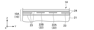
- FIG. FIG. 2 is a sectional view taken along the line VV in FIG. 1.
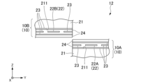
- 2 is a sectional view taken along the line VI-VI in FIG. 1.
- FIG. 2 is a sectional view taken along the line VII-VII in FIG. 1.
- FIG. 1 is a perspective view showing an example of a stringed instrument to which a flat cable according to the present invention is applied.
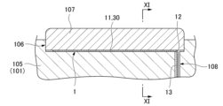
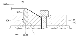
- FIG. 2 is a sectional view showing essential parts of the stringed instrument shown in FIG. 1.
- FIG. 3 is a sectional view taken along the line XI-XI in FIG. 2.
- FIG. 7 is a plan view of a flat cable according to another embodiment of the present invention, showing a state before two sheet-type electrodes overlap.
- the flat cable 1 includes two sheet-type electrodes 10 (10A, 10B) formed in a band shape.
- one of the two sheet-type electrodes 10A may be referred to as a first sheet-type electrode 10A
- the other sheet-type electrode 10B may be referred to as a second sheet-type electrode 10B.
- Each sheet-type electrode 10 is bendable in its thickness direction.
- Each sheet-type electrode 10 has a first portion 11, a second portion 12, and a third portion 13 arranged in order in the longitudinal direction of the sheet-type electrode 10. Further, the first sheet-type electrode 10A has an extension portion 14 that further extends from the third portion 13 in the longitudinal direction.
- two sheet-type electrodes 10 are fixed in an overlapping manner in the thickness direction of the sheet-type electrodes 10. As shown in FIGS.
- two sheet-type electrodes 10 are arranged adjacent to each other in the width direction of the sheet-type electrodes 10, and the two sheet-type electrodes 10 are arranged side by side in the width direction of the sheet-type electrodes 10. Do not overlap.
- the longitudinal direction of the sheet-type electrode 10 is shown as the X-axis direction
- the width direction of the sheet-type electrode 10 is shown as the Y-axis direction
- the thickness direction of the sheet-type electrode 10 is shown as the Z-axis direction.
- the Y-axis positive direction side (+Y side) may be referred to as the right side
- the Y-axis negative direction side (-Y side) may be referred to as the left side
- the Z-axis positive direction side (+Z side) may be called the upper side
- the Z-axis negative direction side (-Z side) may be called the lower side.
- the first sheet-type electrode 10A is arranged on the lower side
- the second sheet-type electrode 10B is arranged on the upper side of the first sheet-type electrode 10A.
- the total width W2t of the two sheet-type electrodes 10 in the second portion 12 is less than or equal to the width dimensions W1, W3 of the sheet-type electrodes 10 in the first portion 11 and third portion 13. There is.
- the sheet-type electrode 10 in the second portion 12 does not protrude outward from the widthwise ends of the sheet-type electrode 10 in the first portion 11 and the third portion 13 .
- the width dimensions W1 and W3 of the two sheet-type electrodes 10 in the first portion 11 and the third portion 13 are equal to each other.
- the width dimension of the extension portion 14 of the first sheet-type electrode 10A is equal to the width dimension W3 of the sheet-type electrode 10 in the third portion 13.
- each width of the two sheet-type electrodes 10 in the second portion 12 is approximately half the width W1, W3 of the sheet-type electrode 10 in the first and third portions 11, 13, respectively.
- the total width W2t of the two sheet-type electrodes 10 in the second portion 12 is equal to the width dimensions W1 and W3 of the sheet-type electrodes 10 in the first portion 11 and the third portion 13.
- the second portion 12 is arranged closer to the right end of the first portion 11 and the third portion 13. Furthermore, in the first sheet-type electrode 10A, the second portion 12 does not protrude outward from the right end of the first portion 11 and third portion 13. On the other hand, in the second sheet-type electrode 10B, the second portion 12 is arranged closer to the left end of the first portion 11 and the third portion 13. Further, in the second sheet-type electrode 10B, the second portion 12 thereof does not protrude outward from the left end of the first portion 11 and the third portion 13. As a result, when the two sheet-type electrodes 10 are overlapped in the thickness direction, the second portion 12 does not protrude outward from the ends of the first portion 11 and the third portion 13 in the width direction.
- the flat cable 1 of this embodiment is used for a piezoelectric sensor 30 having a piezoelectric element 25.
- the piezoelectric element 25 is arranged between the two sheet-type electrodes 10 in the first part 11 .
- the piezoelectric sensor 30 includes two sheet-type electrodes 10 and a piezoelectric element 25, and converts pressure fluctuations such as vibrations into electrical signals.
- the two sheet-type electrodes 10 constituting the flat cable 1 each include a sheet base material 21, an electric wiring 22, a ground wiring 23, and a resist 24.
- the sheet base material 21 is a flexible, belt-shaped sheet material extending in the longitudinal direction.
- the sheet base material 21 may be made of an electrically insulating material such as polyethylene terephthalate (PET).
- PET polyethylene terephthalate
- the planar shape of the sheet base material 21 viewed from the thickness direction corresponds to the planar shape of each sheet-type electrode 10 (the shape shown in FIGS. 1 to 3) when viewed from the thickness direction.
- the electrical wiring 22 is made of a conductive material, is provided on the first surface 211 side in the thickness direction of the sheet base material 21, and extends in the longitudinal direction.
- the electrical wiring 22 functions as an electrode connected to the piezoelectric element 25 in the first portion 11 . In this embodiment, the electrical signal output from the piezoelectric element 25 flows through the electrical wiring 22 .
- the ground wiring 23 is provided on the first surface 211 side of the sheet base material 21 and functions as a shield that electromagnetically protects the electric wiring 22.
- the ground wiring 23 prevents or suppresses, for example, electromagnetic noise from reaching the electrical wiring 22 from the outside.
- the resist 24 is provided on the first surface 211 side of the sheet base material 21, and mainly electrically insulates the electrical wiring 22 and the ground wiring 23 provided on the same sheet-type electrode 10. Further, the resist 24 electrically insulates the ground wirings 23 provided on the same sheet-type electrode 10 or the electrical wirings 22 from each other.
- the arrangement of the electrical wiring 22 and the ground wiring 23 on the first surface 211 of the sheet base material 21 differs depending on the position of the sheet-type electrode 10 in the longitudinal direction, and also differs between the two sheet-type electrodes 10. This point will be mainly explained below.
- each sheet-type electrode 10 a ground wiring 23 and an electric wiring 22 are laminated in order on the first surface 211 of the sheet base material 21.
- the ground wiring 23 and the electric wiring 22 are electrically insulated by a resist 24 interposed between them.
- the width dimension of the electric wiring 22 in the first portion 11 is smaller than the width dimension of the sheet base material 21 and the ground wiring 23. Both ends of the electrical wiring 22 in the width direction are located inside of both ends of the sheet base material 21 and the ground wiring 23 in the width direction.
- the first surfaces 211 of the sheet base materials 21 of the two sheet-type electrodes 10 face each other, and the electrical wiring 22 of the two sheet-type electrodes 10 is electrically insulated.
- Two sheet-type electrodes 10 are fixed to each other.
- two sheet-type electrodes 10 are fixed to each other with a piezoelectric element 25 sandwiched between them.
- the electrical wiring 22 and piezoelectric element 25 of each sheet-type electrode 10 are adhesively fixed with an adhesive 26 having anisotropic conductivity.
- a piezoelectric sensor 30 is constituted by these piezoelectric elements 25 and the electrical wiring 22 of the two sheet-type electrodes 10.
- each sheet-type electrode 10 As shown in FIG. 5, in the second portion 12 of each sheet-type electrode 10, a first ground wiring 23, an electric wiring 22, and a second ground wiring 23 are arranged on the first surface 211 of the sheet base material 21. They are stacked in order. Furthermore, ground wiring 23 is arranged on both sides of the electric wiring 22 in the width direction. Thereby, the electrical wiring 22 of each sheet-type electrode 10 is surrounded by the ground wiring 23. These plurality of ground wirings 23 and electric wirings 22 are electrically insulated by a resist 24 interposed between them. Further, the resist 24 is also laminated on the second ground wiring 23 to prevent the second ground wiring 23 from being exposed to the outside.
- the width of the electrical wiring 22 in the second portion 12 is smaller than the width of the sheet base material 21 and the width of the ground wiring 23 that overlaps the electrical wiring 22 in the thickness direction. Both ends of the electrical wiring 22 in the width direction are located inside of both ends of the sheet base material 21 and the ground wiring 23 in the width direction.
- the two sheet electrodes 10 are positioned shifted in the width direction with the first surfaces 211 of the sheet base materials 21 of the two sheet electrodes 10 facing oppositely to each other in the thickness direction. do.
- the first surfaces 211 of the sheet base materials 21 of the two sheet-type electrodes 10 face each other, as in the first portion 11.
- Two sheet-type electrodes 10 are fixed to each other.
- the two sheet-type electrodes 10 are directly fixed with adhesive 27.
- the adhesive 27 has electrical insulation properties.
- the third portion 13 is configured such that the electrical wiring 22 and ground wiring 23 of the two sheet-type electrodes 10 are integrated into the first sheet-type electrode 10A.
- the third portion 13 of the two sheet-type electrodes 10 includes a portion where the second electrical wiring 22B of the second sheet-type electrode 10B is transferred to the first sheet-type electrode 10A as shown in FIG. There is a portion where the ground wiring 23 of the second sheet-type electrode 10B is transferred to the first sheet-type electrode 10A.
- the first sheet The first electrical wiring 22A of the mold electrode 10A is surrounded by the ground wiring 23.
- the second electrical wiring 22B of the second sheet-type electrode 10B is arranged so as to be surrounded by the ground wiring 23, but is exposed on the first sheet-type electrode 10A side in the thickness direction.
- an electric wiring 22 (second electric wiring 22B) connected to the second electric wiring 22B of the second sheet-type electrode 10B is formed in the same layer as the first electric wiring 22A. ing.
- the second electrical wiring 22B formed on the first sheet electrode 10A is exposed on the second sheet electrode 10B side so as to face the second electrical wiring 22B of the second sheet electrode 10B in the thickness direction.
- Second electrical wiring 22B formed on the opposing first and second sheet-type electrodes 10A and 10B is electrically connected by a connecting member 28. Thereby, the second electrical wiring 22B of the second sheet-type electrode 10B is transferred to the first sheet-type electrode 10A. That is, the first and second electrical wirings 22A, 22B are integrated into the first sheet-type electrode 10A.
- FIG. 7 shows a portion of the third portion 13 where the ground wiring 23 of the second sheet-type electrode 10B is transferred to the first sheet-type electrode 10A. This portion is located further away from the second portion 12 in the longitudinal direction than the portion that transfers the second electrical wiring 22B from the second sheet-type electrode 10B to the first sheet-type electrode 10A (see FIG. 1). As shown in FIG. 7, in the part where the ground wiring 23 of the second sheet-type electrode 10B is transferred to the first sheet-type electrode 10A, the first electric wiring 22A and the second electric wiring provided on the first sheet-type electrode 10A are 22B are lined up in the width direction in a state where they are electrically insulated from each other.
- first electric wiring 22A and second electric wiring 22B are surrounded by the ground wiring 23 and are not exposed to the outside of the first sheet-type electrode 10A.
- first ground wiring 23, the first electrical wiring 22A, the second electrical wiring 22B, and the second ground wiring 23 are laminated in order on the first surface 211 of the sheet base material 21. ing.
- ground wiring 23 is also arranged on both sides of the first electric wiring 22A and the second electric wiring 22B in the width direction. Only the ground wiring 23 remains in the second sheet-type electrode 10B.
- the ground wiring 23 of the first sheet-type electrode 10A is exposed toward the second sheet-type electrode 10B in the thickness direction.
- the ground wiring 23 of the second sheet-type electrode 10B is exposed on the first sheet-type electrode 10A side so as to face the ground wiring 23 of the first sheet-type electrode 10A in the thickness direction.
- the ground wires 23 of the opposing first and second sheet-type electrodes 10A and 10B are electrically connected by a connecting member 29. Thereby, the ground wiring 23 of the second sheet-type electrode 10B is transferred to the first sheet-type electrode 10A. That is, the ground wiring 23 is integrated into the first sheet-type electrode 10A.
- the first electrical connection lines and Second electric wirings 22B each extend in the longitudinal direction. That is, the extension portion 14 includes a first electrical wiring 22A and a second electrical wiring 22B.
- the first electrical wiring 22A, the second electrical wiring 22B, and the ground wiring 23 are arranged similarly to the third portion 13 of the first sheet-type electrode 10A. That is, in the extension portion 14 as well, the first electrical wiring 22A and the second electrical wiring 22B are surrounded by the ground wiring 23.
- the first electrical wiring 22A, the second electrical wiring 22B, and the plurality of ground wirings 23 are electrically insulated by a resist 24 interposed between them. Further, in the extension portion 14, the resist 24 covers the ground wiring 23 so that the ground wiring 23 is not exposed to the outside.
- connection terminal 15 for connecting the first electrical wiring 22A, the second electrical wiring 22B, and the ground wiring 23 to a device is provided at the tip of the extension portion 14 in the extending direction. It is provided.
- the two sheet-type electrodes 10 are not fixed to each other in the second portion 12 and are arranged adjacent to each other in the width direction of the sheet-type electrodes 10. Therefore, when the flat cable 1 is bent in the thickness direction of the sheet-type electrode 10 at the second portion 12, the two sheet-type electrodes 10 are bent independently so as not to interfere with each other. Thereby, stress can be suppressed from being generated between the two sheet-type electrodes 10 fixed to each other in the first portion 11 and the third portion 13 based on the bending of the flat cable 1. Therefore, even if the flat cable 1 is bent, separation of the two sheet-type electrodes 10 at the first portion 11 and the third portion 13 can be suppressed.
- the total width W2t of the two sheet-type electrodes 10 in the second portion 12 is equal to the width W1 of each of the two sheet-type electrodes 10 in the first portion 11 and the third portion 13. , W3 or lower.
- the width dimension W2t of the flat cable 1 in the second portion 12 can be prevented from becoming larger than the width dimensions W1 and W3 of the flat cable 1 in the first portion 11 and the third portion 13.
- the ease of handling of the flat cable 1 can be improved compared to the case where the width dimension W2t of the second portion 12 is larger than the width dimensions W1 and W3 of the first portion 11 and the third portion 13.
- the electrical wiring 22 of the two sheet-type electrodes 10 is integrated into the first sheet-type electrode 10A in the third portion 13, and the first sheet-type electrode 10A further extends from the third portion 13.
- the extension 14 includes the consolidated electrical wiring 22 .
- the thickness of the flat cable 1 further extending from the third portion 13 can be reduced.
- the thickness of the flat cable 1 further extending from the third portion 13 can be made equal to the thickness of one sheet-type electrode 10.
- the two sheet-type electrodes 10 are not fixed in an overlapping manner as in the first part 11 and the third part 13, so compared to the first part 11 and the third part 13, The flat cable 1 has excellent flexibility.
- the flat cable 1 of this embodiment includes a piezoelectric element 25 disposed between the two sheet-type electrodes 10 in the first portion 11.
- the two sheet-type electrodes 10 and the piezoelectric element 25 can constitute a piezoelectric sensor 30 that converts pressure fluctuations such as vibrations into electrical signals.
- a piezoelectric sensor 30 including two sheet-type electrodes 10 can be used, for example, in a guitar 100 (stringed instrument) shown in FIGS. 9 to 11. Specifically, the piezoelectric sensor 30 can be used as a guitar pickup that detects vibrations of the strings 103. This point will be explained below.
- the guitar 100 shown in FIG. 9 has a body 101, a neck 102 extending from the body 101, and strings 103 stretched between the body 101 and the tip of the neck 102.
- a first end of the string 103 is fixed to the bridge 105 of the body 101, and a second end of the string 103 is wound up by a winder 104 provided at the tip of the neck 102.
- the strings 103 are supported by saddles 107 that fit into grooves 106 formed in the bridge 105 of the body 101.
- the saddle 107 supports the string 103 on the first end side of the string 103.
- the first portion 11 of the flat cable 1 configured as the piezoelectric sensor 30 is arranged between the bottom surface of the groove 106 of the body 101 and the saddle 107. Furthermore, the flat cable 1 is pulled out to the outside of the groove 106 in order to connect the piezoelectric sensor 30 to a device (not shown) placed outside the groove 106. Specifically, the third portion 13 of the flat cable 1 is inserted into the hole 108 that opens and extends from the bottom of the groove 106, so that the third portion 13 and the extension portion 14 (see FIGS. 1 and 3) are inserted into the groove. 106. Then, the connection terminal 15 of the extension part 14 is connected to a device (not shown).
- the flat cable 1 is bent at the second portion 12 located between the first portion 11 and the third portion 13 of the flat cable 1.
- stress is suppressed from being generated in the first portion 11 based on the bending. Therefore, peeling of the sheet-type electrode 10 from the piezoelectric element 25 (see FIG. 4) at the first portion 11 can be suppressed. That is, it is possible to prevent problems from occurring in the piezoelectric sensor 30 due to bending of the flat cable 1.
- the piezoelectric sensor 30 including the flat cable 1 is attached to the guitar 100, the vibration of the string 103 is transmitted to the piezoelectric sensor 30 via the saddle 107 and converted into an electrical signal.
- the electrical signal is transmitted by the electrical wiring 22 of the flat cable 1 to a device (not shown) placed outside the groove 106.
- the two sheet-type electrodes 10 are not limited to being formed separately as in the above embodiment, but may be formed integrally, for example, as shown in FIG. 12.
- the two sheet-type electrodes 10 are integrally formed, the two sheet-type electrodes 10 are folded at the first portion 11 and the third portion 13 by bending the two sheet-type electrodes 10 at the boundary line 17. Can be stacked. Further, the two sheet-type electrodes 10 can be placed adjacent to each other in the width direction in the second portion 12. In FIG. 12, the ends of the two sheet-type electrodes 10 in the width direction are connected to each other, but for example, the ends of the two sheet-type electrodes 10 in the longitudinal direction may be connected to each other.
- the width dimensions of the two sheet-type electrodes 10 in the second portion 12 may be different from each other, for example.
- the total width W2t of the two sheet-type electrodes 10 in the second portion 12 is, for example, less than or equal to the width dimension of the sheet-type electrode 10 in one of the first portion 11 and the third portion 13, and It may be larger than the width dimension of the sheet-type electrode 10 at the other of the portion 11 and the third portion 13.
- the width dimension W2t of the two sheet-type electrodes 10 in the second portion 12 may be larger than the width dimensions W1 and W3 of the sheet-type electrodes 10 in both the first portion 11 and the third portion 13, for example.
- the sheet-type electrode 10 in the second portion 12 may protrude outward from the end of the sheet-type electrode 10 in the first portion 11 and/or the third portion 13 in the width direction.
- the electrical wiring 22 of the two sheet-type electrodes 10 does not need to be integrated into the first sheet-type electrode 10A in the third portion 13, for example.
- a connection terminal for connecting the electrical wiring 22 to a device may be provided at the ends of the two sheet-type electrodes 10 in the extending direction.
- the number of sheet-type electrodes included in the flat cable is not limited to two, but may be a plurality. Therefore, in the first portion and the third portion of the sheet-type electrode, a plurality of sheet-type electrodes may be stacked and fixed in the thickness direction thereof. Moreover, in the second portion of the sheet-type electrode, a plurality of sheet-type electrodes may be arranged adjacent to each other in the width direction of the sheet-type electrode.
Landscapes
- Insulated Conductors (AREA)
Abstract
フラットケーブル1は、帯状に形成された二つのシート型電極10を備える。シート型電極10は、シート型電極10の長手方向に順番に並ぶ第一部分11、第二部分12及び第三部分13を有する。第一部分11及び第三部分13では、二つのシート型電極10がシート型電極10の厚さ方向に重ねて固定され、第二部分12では、二つのシート型電極10がシート型電極10の幅方向に隣り合わせて配置されている。
Description
本発明は、フラットケーブルに関する。
特許文献1には、帯状に形成された二つのシート型電極を、シート型電極の厚さ方向に重ねて固定したフラットケーブルが開示されている。
しかしながら、このようなフラットケーブルをシート型電極の厚さ方向に屈曲すると、フラットケーブルの屈曲部分では、二つのシート型電極のうち屈曲部分の径方向内側に位置するシート型電極が圧縮され、径方向外側に位置するシート型電極が伸長する。このため、互いに固定された二つのシート型電極の間に応力が生じ、これら二つのシート型電極が剥離してしまう、という問題がある。なお、フラットケーブルが、二つのシート型電極の間に圧電素子を設けた振動センサ(ピックアップ)を含む場合、フラットケーブルの屈曲に伴ってシート型電極が圧電素子から剥離する虞がある。
本発明は、上述した事情に鑑みてなされたものであって、屈曲しても二つのシート型電極の剥離を抑制することが可能なフラットケーブルを提供することを目的とする。
本発明の一態様は、帯状に形成された少なくとも二つのシート型電極を備え、前記シート型電極は、前記シート型電極の長手方向に順番に並ぶ第一部分、第二部分及び第三部分を有し、前記第一部分及び前記第三部分では、二つの前記シート型電極が前記シート型電極の厚さ方向に重ねて固定され、前記第二部分では、二つの前記シート型電極が前記シート型電極の幅方向に隣り合わせて配置されているフラットケーブルである。
本発明によれば、フラットケーブルを屈曲しても二つのシート型電極の剥離を抑制することができる。
以下、図1~11を参照して本発明の一実施形態について説明する。
図1~3に示すように、フラットケーブル1は、帯状に形成された二つのシート型電極10(10A,10B)を備える。以下の説明では、二つのシート型電極10Aの一方を第一シート型電極10Aと呼び、他方のシート型電極10Bを第二シート型電極10Bと呼ぶことがある。
図1~3に示すように、フラットケーブル1は、帯状に形成された二つのシート型電極10(10A,10B)を備える。以下の説明では、二つのシート型電極10Aの一方を第一シート型電極10Aと呼び、他方のシート型電極10Bを第二シート型電極10Bと呼ぶことがある。
各シート型電極10は、その厚さ方向に屈曲可能である。各シート型電極10は、シート型電極10の長手方向に順番に並ぶ第一部分11、第二部分12及び第三部分13を有する。また、第一シート型電極10Aは、第三部分13からさらに長手方向に延びる延長部14を有する。図4,6,7に示すように、第一部分11及び第三部分13においては、二つのシート型電極10が当該シート型電極10の厚さ方向に重ねて固定されている。図2,5に示すように、第二部分12においては、二つのシート型電極10が当該シート型電極10の幅方向に隣り合わせて配置され、二つのシート型電極10はこれらの厚さ方向に重ならない。
図1~8においては、シート型電極10の長手方向がX軸方向で示されており、シート型電極10の幅方向がY軸方向で示されている。また、シート型電極10の厚さ方向がZ軸方向で示されている。以下の説明では、Y軸正方向側(+Y側)を右側と呼び、Y軸負方向側(-Y側)を左側と呼ぶことがある。また、Z軸正方向側(+Z側)を上側と呼び、Z軸負方向側(-Z側)を下側と呼ぶことがある。
本実施形態では、第一シート型電極10Aが下側に配置され、第二シート型電極10Bが第一シート型電極10Aの上側に配置される。
本実施形態では、第一シート型電極10Aが下側に配置され、第二シート型電極10Bが第一シート型電極10Aの上側に配置される。
図2に示すように、第二部分12における二つのシート型電極10の各幅寸法の合計W2tは、第一部分11及び第三部分13におけるシート型電極10の幅寸法W1,W3以下となっている。第二部分12におけるシート型電極10は、第一部分11及び第三部分13におけるシート型電極10の幅方向の端から外側に張り出さない。
具体的に説明すれば、第一部分11及び第三部分13における二つのシート型電極10の幅寸法W1,W3は、互いに等しい。また、第一シート型電極10Aの延長部14の幅寸法は、第三部分13におけるシート型電極10の幅寸法W3と等しい。一方、第二部分12における二つのシート型電極10の各幅寸法は、それぞれ第一、第三部分11,13におけるシート型電極10の幅寸法W1,W3の略半分となっている。これにより、第二部分12における二つのシート型電極10の幅寸法の合計W2tが、第一部分11及び第三部分13におけるシート型電極10の幅寸法W1,W3と等しくなっている。
また、第一シート型電極10Aでは、その第二部分12が、第一部分11及び第三部分13の右側の端に寄せて配置されている。また、第一シート型電極10Aでは、その第二部分12が、第一部分11及び第三部分13の右側の端から外側に張り出さない。一方、第二シート型電極10Bでは、その第二部分12が、第一部分11及び第三部分13の左側の端に寄せて配置されている。また、第二シート型電極10Bでは、その第二部分12が、第一部分11及び第三部分13の左側の端から外側に張り出さない。これにより、二つのシート型電極10を厚さ方向に重ねた状態では、第二部分12が、幅方向における第一部分11及び第三部分13の端から外側に張り出さない。
図4に示すように、本実施形態のフラットケーブル1は、圧電素子25を有する圧電センサ30に用いられる。圧電素子25は、第一部分11において二つのシート型電極10の間に配置される。圧電センサ30は、二つのシート型電極10及び圧電素子25によって構成され、振動などの圧力変動を電気信号に変換する。
以下、本実施形態のフラットケーブル1について、より具体的に説明する。
図4~8に示すように、フラットケーブル1を構成する二つのシート型電極10は、それぞれ、シート基材21と、電気配線22と、グランド配線23と、レジスト24と、を備える。
図4~8に示すように、フラットケーブル1を構成する二つのシート型電極10は、それぞれ、シート基材21と、電気配線22と、グランド配線23と、レジスト24と、を備える。
シート基材21は、可撓性を有し、長手方向に延びる帯状のシート材である。シート基材21は、例えばポリエチレンテレフタレート(PET)などのように電気的な絶縁性を有する材料によって構成されてよい。厚さ方向から見たシート基材21の平面視形状は、厚さ方向から見た各シート型電極10の平面視形状(図1~3に示した形状)に対応している。
電気配線22は、導電性材料からなり、シート基材21の厚さ方向の第一面211側に設けられて長手方向に延びる。電気配線22は、第一部分11において圧電素子25に接続される電極として機能する。本実施形態において、電気配線22には、圧電素子25から出力された電気信号が流れる。
電気配線22は、導電性材料からなり、シート基材21の厚さ方向の第一面211側に設けられて長手方向に延びる。電気配線22は、第一部分11において圧電素子25に接続される電極として機能する。本実施形態において、電気配線22には、圧電素子25から出力された電気信号が流れる。
グランド配線23は、シート基材21の第一面211側に設けられ、電気配線22を電磁気的に保護するシールドとして機能する。グランド配線23は、例えば電磁気的なノイズが外部から電気配線22に到達することを防止又は抑制する。
レジスト24は、シート基材21の第一面211側に設けられ、主に同一のシート型電極10に設けられた電気配線22とグランド配線23とを電気的に絶縁する。また、レジスト24は、同一のシート型電極10に設けられたグランド配線23同士、あるいは、電気配線22同士を電気的に絶縁する。
レジスト24は、シート基材21の第一面211側に設けられ、主に同一のシート型電極10に設けられた電気配線22とグランド配線23とを電気的に絶縁する。また、レジスト24は、同一のシート型電極10に設けられたグランド配線23同士、あるいは、電気配線22同士を電気的に絶縁する。
シート基材21の第一面211上における電気配線22及びグランド配線23の配置は、長手方向におけるシート型電極10の位置に応じて異なり、また、二つのシート型電極10の間でも異なる。以下、主にこの点について説明する。
図4に示すように、各シート型電極10の第一部分11においては、シート基材21の第一面211にグランド配線23と電気配線22とが順番に積層されている。グランド配線23と電気配線22とは、これらの間に介在するレジスト24によって電気的に絶縁されている。第一部分11における電気配線22の幅寸法は、シート基材21、グランド配線23の幅寸法よりも小さい。幅方向における電気配線22の両端は、幅方向におけるシート基材21、グランド配線23の両端よりも内側に位置する。
第一部分11においては、二つのシート型電極10のシート基材21の第一面211が対向するように、かつ、二つのシート型電極10の電気配線22が電気的に絶縁されるように、二つのシート型電極10が互いに固定される。本実施形態では、二つのシート型電極10は、これらの間に圧電素子25を挟んで互いに固定される。各シート型電極10の電気配線22と圧電素子25とは、異方導電性を有する接着剤26によって接着固定される。これら圧電素子25及び二つのシート型電極10の電気配線22によって、圧電センサ30が構成される。
図5に示すように、各シート型電極10の第二部分12においては、シート基材21の第一面211に一つ目のグランド配線23と電気配線22と二つ目のグランド配線23が順番に積層されている。また、幅方向における電気配線22の両側にもグランド配線23が配置されている。これにより、各シート型電極10の電気配線22は、グランド配線23によって囲まれている。これら複数のグランド配線23及び電気配線22は、これらの間に介在するレジスト24によって電気的に絶縁されている。また、レジスト24は、二つ目のグランド配線23の上にも積層され、二つ目のグランド配線23が外部に露出することを抑制している。第二部分12における電気配線22の幅寸法は、シート基材21の幅寸法、及び、電気配線22と厚さ方向に重なるグランド配線23の幅寸法よりも小さい。幅方向における電気配線22の両端は、幅方向におけるシート基材21及びグランド配線23の両端よりも内側に位置する。
第二部分12においては、二つのシート型電極10のシート基材21の第一面211を厚さ方向において互いに逆側に向けた状態で、二つのシート型電極10が幅方向にずれて位置する。
第二部分12においては、二つのシート型電極10のシート基材21の第一面211を厚さ方向において互いに逆側に向けた状態で、二つのシート型電極10が幅方向にずれて位置する。
図6,7に示すように、二つのシート型電極10の第三部分13においては、第一部分11と同様に、二つのシート型電極10のシート基材21の第一面211が対向するように二つのシート型電極10が互いに固定される。ただし、第三部分13においては、二つのシート型電極10が接着剤27によって直接固定される。当該接着剤27は、電気的な絶縁性を有する。
第三部分13は、二つのシート型電極10の電気配線22及びグランド配線23が、第一シート型電極10Aに集約されるように構成されている。二つのシート型電極10の第三部分13には、図6に示すように第二シート型電極10Bの第二電気配線22Bを第一シート型電極10Aに移す部分と、図7に示すように第二シート型電極10Bのグランド配線23を第一シート型電極10Aに移す部分とがある。これら二つの部分は、互いに長手方向にずれて位置する。
第三部分13は、二つのシート型電極10の電気配線22及びグランド配線23が、第一シート型電極10Aに集約されるように構成されている。二つのシート型電極10の第三部分13には、図6に示すように第二シート型電極10Bの第二電気配線22Bを第一シート型電極10Aに移す部分と、図7に示すように第二シート型電極10Bのグランド配線23を第一シート型電極10Aに移す部分とがある。これら二つの部分は、互いに長手方向にずれて位置する。
図6に示すように、第三部分13のうち、第二シート型電極10Bの第二電気配線22Bを第一シート型電極10Aに移す部分においては、第二部分12と同様に、第一シート型電極10Aの第一電気配線22Aがグランド配線23によって囲まれるように配置されている。第二シート型電極10Bの第二電気配線22Bは、グランド配線23によって囲まれるように配置されているが、厚さ方向において第一シート型電極10A側に露出している。また、第一シート型電極10Aには、第一電気配線22Aと同じ層に、第二シート型電極10Bの第二電気配線22Bに接続される電気配線22(第二電気配線22B)が形成されている。第一シート型電極10Aに形成された第二電気配線22Bは、厚さ方向において第二シート型電極10Bの第二電気配線22Bに対向するように第二シート型電極10B側に露出している。そして、対向する第一、第二シート型電極10A,10Bに形成された第二電気配線22Bが接続部材28によって電気的に接続されている。これにより、第二シート型電極10Bの第二電気配線22Bが第一シート型電極10Aに移される。すなわち、第一、第二電気配線22A,22Bが第一シート型電極10Aに集約される。
図7は、第三部分13のうち、第二シート型電極10Bのグランド配線23を第一シート型電極10Aに移す部分を示している。当該部分は、第二電気配線22Bを第二シート型電極10Bから第一シート型電極10Aに移す部分よりも第二部分12から長手方向に離れて位置する(図1参照)。図7に示すように、第二シート型電極10Bのグランド配線23を第一シート型電極10Aに移す部分においては、第一シート型電極10Aに設けられた第一電気配線22A及び第二電気配線22Bが互いに電気的に絶縁された状態で幅方向に並んでいる。また、これら第一電気配線22A及び第二電気配線22Bは、グランド配線23によって囲まれ、第一シート型電極10Aの外側に露出しない。具体的には、シート基材21の第一面211に一つ目のグランド配線23と、第一電気配線22A及び第二電気配線22Bと、二つ目のグランド配線23とが順番に積層されている。また、幅方向における第一電気配線22A及び第二電気配線22Bの両側にもグランド配線23が配置されている。第二シート型電極10Bには、グランド配線23のみが残っている。
さらに、図7に示す部分においては、第一シート型電極10Aのグランド配線23が厚さ方向において第二シート型電極10B側に露出している。また、第二シート型電極10Bのグランド配線23が厚さ方向において第一シート型電極10Aのグランド配線23に対向するように第一シート型電極10A側に露出している。そして、対向する第一、第二シート型電極10A,10Bのグランド配線23が接続部材29によって電気的に接続されている。これにより、第二シート型電極10Bのグランド配線23が第一シート型電極10Aに移される。すなわち、グランド配線23が第一シート型電極10Aに集約される。
図8に示すように、第一シート型電極10Aの第三部分13からさらに長手方向に延びる延長部14では、第三部分13において第一シート型電極10Aに集約された第一電気接続線及び第二電気配線22Bが、それぞれ長手方向に延びている。すなわち、延長部14は、第一電気配線22A及び第二電気配線22Bを含む。当該延長部14においては、第一シート型電極10Aの第三部分13と同様に、第一電気配線22A、第二電気配線22B及びグランド配線23が配置されている。すなわち、延長部14においても、第一電気配線22A及び第二電気配線22Bが、グランド配線23によって囲まれている。これら第一電気配線22A、第二電気配線22B及び複数のグランド配線23は、これらの間に介在するレジスト24によって電気的に絶縁されている。また、延長部14において、レジスト24は、グランド配線23が外部に露出しないようにグランド配線23を覆っている。
図1,3に示すように、延長部14の延長方向の先端には、第一電気配線22A、第二電気配線22B、グランド配線23を、不図示の機器に接続するための接続端子15が設けられている。
以上のように構成される本実施形態のフラットケーブル1では、二つのシート型電極10が、第二部分12において互いに固定されず、かつ、シート型電極10の幅方向に隣り合わせて配置される。このため、第二部分12においてフラットケーブル1をシート型電極10の厚さ方向に屈曲した際、二つのシート型電極10は互いに干渉しないように各々独立して屈曲する。これにより、フラットケーブル1の屈曲に基づいて、第一部分11及び第三部分13において互いに固定された二つのシート型電極10の間に応力が発生することを抑制できる。したがって、フラットケーブル1を屈曲しても、二つのシート型電極10が第一部分11及び第三部分13において剥離することを抑制することができる。
また、本実施形態のフラットケーブル1では、第二部分12における二つのシート型電極10の幅寸法の合計W2tが、第一部分11及び第三部分13における二つのシート型電極10の各幅寸法W1,W3以下となっている。このため、第二部分12におけるフラットケーブル1の幅寸法W2tが、第一部分11及び第三部分13におけるフラットケーブル1の幅寸法W1,W3よりも大きくなることを防ぐことができる。これにより、第二部分12の幅寸法W2tが、第一部分11及び第三部分13の幅寸法W1,W3よりも大きい場合と比較して、フラットケーブル1の取り扱い性の向上を図ることができる。
また、本実施形態のフラットケーブル1では、第三部分13において二つのシート型電極10の電気配線22が第一シート型電極10Aに集約され、第三部分13からさらに延びる第一シート型電極10Aの延長部14が、集約された電気配線22を含んでいる。これにより、第三部分13からさらに延びるフラットケーブル1の厚さを薄くすることができる。具体的に、第三部分13からさらに延びるフラットケーブル1の厚さを一つのシート型電極10の厚さとすることができる。また、フラットケーブル1の延長部14においては、第一部分11及び第三部分13のように二つのシート型電極10が重ねて固定されていないため、第一部分11及び第三部分13と比較してフラットケーブル1の屈曲性に優れる。
また、本実施形態のフラットケーブル1は、第一部分11において二つのシート型電極10の間に配置される圧電素子25を備える。これにより、二つのシート型電極10及び圧電素子25によって、振動などの圧力変動を電気信号に変換する圧電センサ30を構成することができる。
二つのシート型電極10(すなわちフラットケーブル1)を含む圧電センサ30は、例えば図9~11に示すギター100(弦楽器)に利用することができる。具体的には、圧電センサ30を、弦103の振動を検出するギターピックアップとして利用することができる。以下、この点について説明する。
図9に示すギター100は、胴部101と、胴部101から延びるネック102と、胴部101とネック102の先端との間で張られる弦103と、を有する。弦103の第一端部は、胴部101のブリッジ105に固定され、弦103の第二端部は、ネック102の先端に設けられた巻き取り器104によって巻き取られる。図10,11に示すように、弦103は、胴部101のブリッジ105に形成された溝106に嵌まるサドル107によって支持される。サドル107は、弦103の第一端部側において弦103を支持する。
圧電センサ30として構成されるフラットケーブル1の第一部分11は、胴部101の溝106の底面とサドル107との間に配置される。また、フラットケーブル1は、圧電センサ30を溝106の外側に配置された不図示の機器に接続するために、溝106の外側に引き出される。具体的には、フラットケーブル1の第三部分13が、溝106の底面に開口して延びる孔108に挿入されることで、第三部分13及び延長部14(図1,3参照)が溝106の外側に引き出される。そして、延長部14の接続端子15が不図示の機器に接続される。
ここで、溝106の底面が延びる方向と、溝106に連なる孔108が延びる方向とは、互いに異なっている。このため、フラットケーブル1の第一部分11と第三部分13との間に位置する第二部分12において、フラットケーブル1が屈曲する。ただし、前述したように、第二部分12においてフラットケーブル1が屈曲しても、当該屈曲に基づいて第一部分11に応力が発生することは抑制される。このため、第一部分11においてシート型電極10が圧電素子25(図4参照)から剥離することを抑制できる。すなわち、フラットケーブル1の屈曲に基づいて圧電センサ30に不具合が生じることを抑制することができる。
そして、上記したようにフラットケーブル1を含む圧電センサ30がギター100に装着された状態では、弦103の振動が、サドル107を介して圧電センサ30に伝わることで、電気信号に変換される。当該電気信号は、フラットケーブル1の電気配線22により、溝106の外側に配置された不図示の機器に伝達される。
以上、本発明について詳細に説明したが、本発明は上記実施形態に限定されるものではなく、本発明の趣旨を逸脱しない範囲において種々の変更を加えることが可能である。
本発明において、二つのシート型電極10は、上記実施形態のように別個に形成されることに限らず、例えば図12に示すように、一体に形成されてもよい。二つのシート型電極10が一体に形成される場合には、これら二つのシート型電極10をこれらの境界線17において折り曲げることで、二つのシート型電極10を第一部分11及び第三部分13において重ねることができる。また、二つのシート型電極10を第二部分12において幅方向に隣り合わせることができる。
図12においては、二つのシート型電極10の幅方向の端部同士が接続されているが、例えば、二つのシート型電極10の長手方向の端部同士が接続されてもよい。
図12においては、二つのシート型電極10の幅方向の端部同士が接続されているが、例えば、二つのシート型電極10の長手方向の端部同士が接続されてもよい。
本発明において、第二部分12における二つのシート型電極10の幅寸法は、例えば互いに異なっていてもよい。
また、本発明において、第二部分12における二つのシート型電極10の各幅寸法の合計W2tは、例えば第一部分11及び第三部分13の一方におけるシート型電極10の幅寸法以下であり、第一部分11及び第三部分13の他方におけるシート型電極10の幅寸法よりも大きくてもよい。また、第二部分12における二つのシート型電極10の幅寸法W2tは、例えば第一部分11及び第三部分13の両方におけるシート型電極10の幅寸法W1,W3よりも大きくてもよい。また、第二部分12におけるシート型電極10が、幅方向において、第一部分11及び/又は第三部分13におけるシート型電極10の端から外側に張り出してもよい。
また、本発明において、第二部分12における二つのシート型電極10の各幅寸法の合計W2tは、例えば第一部分11及び第三部分13の一方におけるシート型電極10の幅寸法以下であり、第一部分11及び第三部分13の他方におけるシート型電極10の幅寸法よりも大きくてもよい。また、第二部分12における二つのシート型電極10の幅寸法W2tは、例えば第一部分11及び第三部分13の両方におけるシート型電極10の幅寸法W1,W3よりも大きくてもよい。また、第二部分12におけるシート型電極10が、幅方向において、第一部分11及び/又は第三部分13におけるシート型電極10の端から外側に張り出してもよい。
本発明において、二つのシート型電極10の電気配線22は、例えば第三部分13において第一シート型電極10Aに集約されなくてもよい。この場合、二つのシート型電極10の延長方向の先端に、電気配線22を不図示の機器に接続するための接続端子が設けられてよい。
本発明において、フラットケーブルが備えるシート型電極の数は、二つに限らず、複数であればよい。このため、シート型電極の第一部分及び第三部分では、複数のシート型電極がこれらの厚さ方向に重ねて固定されればよい。また、シート型電極の第二部分では、複数のシート型電極がシート型電極の幅方向に隣り合わせて配置されていればよい。
1…フラットケーブル、10…シート型電極、10A…第一シート型電極、10B…第二シート型電極、11…第一部分、12…第二部分、13…第三部分、14…延長部、21…シート基材、211…シート基材21の第一面、22…電気配線、25…圧電素子
Claims (4)
- 帯状に形成された少なくとも二つのシート型電極を備え、
前記シート型電極は、前記シート型電極の長手方向に順番に並ぶ第一部分、第二部分及び第三部分を有し、
前記第一部分及び前記第三部分では、二つの前記シート型電極が前記シート型電極の厚さ方向に重ねて固定され、
前記第二部分では、二つの前記シート型電極が前記シート型電極の幅方向に隣り合わせて配置されているフラットケーブル。 - 前記第二部分における二つの前記シート型電極の各幅寸法の合計は、前記第一部分及び前記第三部分のうち少なくとも一方における二つの前記シート型電極の各幅寸法以下である請求項1に記載のフラットケーブル。
- 二つの前記シート型電極は、それぞれ、前記長手方向に延びる帯状のシート基材と、前記シート基材の厚さ方向の第一面側に設けられて前記長手方向に延びる電気配線と、を有し、
前記第一部分においては、二つの前記シート型電極の前記シート基材の第一面が対向するように、かつ、二つの前記シート型電極の前記電気配線が互いに電気的に絶縁されるように、二つの前記シート型電極が互いに固定され、
前記第三部分においては、二つの前記シート型電極の前記シート基材の第一面が対向するように二つの前記シート型電極が互いに固定され、かつ、二つの前記シート型電極の前記電気配線が、二つの前記シート型電極のうち第一シート型電極に集約され、
前記第一シート型電極は、集約された二つの前記電気配線を含んで前記第三部分からさらに延びる延長部を有する請求項1又は請求項2に記載のフラットケーブル。 - 前記第一部分において二つの前記シート型電極の間には、圧電素子が配置される請求項1から請求項3のいずれか一項に記載のフラットケーブル。
Priority Applications (1)
| Application Number | Priority Date | Filing Date | Title |
|---|---|---|---|
| CN202380030005.6A CN119054030A (zh) | 2022-03-24 | 2023-03-10 | 扁平电缆 |
Applications Claiming Priority (2)
| Application Number | Priority Date | Filing Date | Title |
|---|---|---|---|
| JP2022047734A JP7715067B2 (ja) | 2022-03-24 | 2022-03-24 | フラットケーブル |
| JP2022-047734 | 2022-03-24 |
Publications (1)
| Publication Number | Publication Date |
|---|---|
| WO2023182004A1 true WO2023182004A1 (ja) | 2023-09-28 |
Family
ID=88101328
Family Applications (1)
| Application Number | Title | Priority Date | Filing Date |
|---|---|---|---|
| PCT/JP2023/009386 Ceased WO2023182004A1 (ja) | 2022-03-24 | 2023-03-10 | フラットケーブル |
Country Status (3)
| Country | Link |
|---|---|
| JP (1) | JP7715067B2 (ja) |
| CN (1) | CN119054030A (ja) |
| WO (1) | WO2023182004A1 (ja) |
Citations (4)
| Publication number | Priority date | Publication date | Assignee | Title |
|---|---|---|---|---|
| US6162992A (en) * | 1999-03-23 | 2000-12-19 | Cable Design Technologies, Inc. | Shifted-plane core geometry cable |
| US6242683B1 (en) * | 1996-04-17 | 2001-06-05 | Emf Acoustics Oy Ltd. | Stringed musical instrument transducer and method for forming a stringed musical instrument transducer |
| JP2002325325A (ja) * | 2001-04-25 | 2002-11-08 | Auto Network Gijutsu Kenkyusho:Kk | 配線材及びその製造方法 |
| EP1349182A2 (de) * | 2002-03-27 | 2003-10-01 | Nexans | Verfahren zur Herstellung einer Flachleiter-Bandleitung |
Family Cites Families (1)
| Publication number | Priority date | Publication date | Assignee | Title |
|---|---|---|---|---|
| US5900572A (en) | 1996-07-15 | 1999-05-04 | Donald Dean Markley | Pliable pickup for stringed instrument |
-
2022
- 2022-03-24 JP JP2022047734A patent/JP7715067B2/ja active Active
-
2023
- 2023-03-10 CN CN202380030005.6A patent/CN119054030A/zh active Pending
- 2023-03-10 WO PCT/JP2023/009386 patent/WO2023182004A1/ja not_active Ceased
Patent Citations (4)
| Publication number | Priority date | Publication date | Assignee | Title |
|---|---|---|---|---|
| US6242683B1 (en) * | 1996-04-17 | 2001-06-05 | Emf Acoustics Oy Ltd. | Stringed musical instrument transducer and method for forming a stringed musical instrument transducer |
| US6162992A (en) * | 1999-03-23 | 2000-12-19 | Cable Design Technologies, Inc. | Shifted-plane core geometry cable |
| JP2002325325A (ja) * | 2001-04-25 | 2002-11-08 | Auto Network Gijutsu Kenkyusho:Kk | 配線材及びその製造方法 |
| EP1349182A2 (de) * | 2002-03-27 | 2003-10-01 | Nexans | Verfahren zur Herstellung einer Flachleiter-Bandleitung |
Also Published As
| Publication number | Publication date |
|---|---|
| CN119054030A (zh) | 2024-11-29 |
| JP2023141416A (ja) | 2023-10-05 |
| JP7715067B2 (ja) | 2025-07-30 |
Similar Documents
| Publication | Publication Date | Title |
|---|---|---|
| JP2020202060A (ja) | 配線材及びバッテリモジュール | |
| JP5293661B2 (ja) | フラットケーブル | |
| CN112005322A (zh) | 屏蔽扁平电缆 | |
| CN107449350B (zh) | 应变仪 | |
| CN101784874A (zh) | 压电薄膜传感器 | |
| TWI794487B (zh) | 屏蔽扁平電纜 | |
| WO2021131265A1 (ja) | フレキシブル基板及び電子機器 | |
| US20200020917A1 (en) | Structure of connection among circuit body, bus bar and electronic element | |
| CN202076032U (zh) | 屏蔽扁平电缆 | |
| JP2023141416A (ja) | フラットケーブル | |
| CN106030910A (zh) | 布线构件 | |
| US20240373549A1 (en) | Multilayer substrate | |
| JP2018152736A (ja) | センサーユニット | |
| WO2018128045A1 (ja) | 多層基板 | |
| US20250071899A1 (en) | Printed wiring board and coil device | |
| KR20160073860A (ko) | 연성케이블 및 그 제조방법 | |
| JPWO2024009727A5 (ja) | ||
| JP6635142B2 (ja) | 配線部材 | |
| JP2012225685A (ja) | 歪ゲージ用fpc基板 | |
| CN108020156A (zh) | 弯曲传感器 | |
| JP2008010310A (ja) | フレキシブルフラットケーブル | |
| WO2021125014A1 (ja) | フォースセンサ | |
| JP7863259B2 (ja) | センサシート | |
| TWI859879B (zh) | 平面壓電振動模組 | |
| US20250391586A1 (en) | Combined Cable |
Legal Events
| Date | Code | Title | Description |
|---|---|---|---|
| 121 | Ep: the epo has been informed by wipo that ep was designated in this application |
Ref document number: 23774603 Country of ref document: EP Kind code of ref document: A1 |
|
| WWE | Wipo information: entry into national phase |
Ref document number: 202380030005.6 Country of ref document: CN |
|
| NENP | Non-entry into the national phase |
Ref country code: DE |
|
| 122 | Ep: pct application non-entry in european phase |
Ref document number: 23774603 Country of ref document: EP Kind code of ref document: A1 |