WO2023181771A1 - R-t-b系焼結磁石の製造方法 - Google Patents
R-t-b系焼結磁石の製造方法 Download PDFInfo
- Publication number
- WO2023181771A1 WO2023181771A1 PCT/JP2023/006576 JP2023006576W WO2023181771A1 WO 2023181771 A1 WO2023181771 A1 WO 2023181771A1 JP 2023006576 W JP2023006576 W JP 2023006576W WO 2023181771 A1 WO2023181771 A1 WO 2023181771A1
- Authority
- WO
- WIPO (PCT)
- Prior art keywords
- rtb
- molded body
- alloy powder
- powder
- sintered magnet
- Prior art date
- Legal status (The legal status is an assumption and is not a legal conclusion. Google has not performed a legal analysis and makes no representation as to the accuracy of the status listed.)
- Ceased
Links
Images
Classifications
-
- B—PERFORMING OPERATIONS; TRANSPORTING
- B22—CASTING; POWDER METALLURGY
- B22F—WORKING METALLIC POWDER; MANUFACTURE OF ARTICLES FROM METALLIC POWDER; MAKING METALLIC POWDER; APPARATUS OR DEVICES SPECIALLY ADAPTED FOR METALLIC POWDER
- B22F3/00—Manufacture of workpieces or articles from metallic powder characterised by the manner of compacting or sintering; Apparatus specially adapted therefor ; Presses and furnaces
-
- C—CHEMISTRY; METALLURGY
- C22—METALLURGY; FERROUS OR NON-FERROUS ALLOYS; TREATMENT OF ALLOYS OR NON-FERROUS METALS
- C22C—ALLOYS
- C22C33/00—Making ferrous alloys
- C22C33/02—Making ferrous alloys by powder metallurgy
-
- H—ELECTRICITY
- H01—ELECTRIC ELEMENTS
- H01F—MAGNETS; INDUCTANCES; TRANSFORMERS; SELECTION OF MATERIALS FOR THEIR MAGNETIC PROPERTIES
- H01F1/00—Magnets or magnetic bodies characterised by the magnetic materials therefor; Selection of materials for their magnetic properties
- H01F1/01—Magnets or magnetic bodies characterised by the magnetic materials therefor; Selection of materials for their magnetic properties of inorganic materials
- H01F1/03—Magnets or magnetic bodies characterised by the magnetic materials therefor; Selection of materials for their magnetic properties of inorganic materials characterised by their coercivity
- H01F1/032—Magnets or magnetic bodies characterised by the magnetic materials therefor; Selection of materials for their magnetic properties of inorganic materials characterised by their coercivity of hard-magnetic materials
- H01F1/04—Magnets or magnetic bodies characterised by the magnetic materials therefor; Selection of materials for their magnetic properties of inorganic materials characterised by their coercivity of hard-magnetic materials metals or alloys
- H01F1/047—Alloys characterised by their composition
- H01F1/053—Alloys characterised by their composition containing rare earth metals
- H01F1/055—Alloys characterised by their composition containing rare earth metals and magnetic transition metals, e.g. SmCo5
- H01F1/057—Alloys characterised by their composition containing rare earth metals and magnetic transition metals, e.g. SmCo5 and IIIa elements, e.g. Nd2Fe14B
-
- H—ELECTRICITY
- H01—ELECTRIC ELEMENTS
- H01F—MAGNETS; INDUCTANCES; TRANSFORMERS; SELECTION OF MATERIALS FOR THEIR MAGNETIC PROPERTIES
- H01F41/00—Apparatus or processes specially adapted for manufacturing or assembling magnets, inductances or transformers; Apparatus or processes specially adapted for manufacturing materials characterised by their magnetic properties
- H01F41/02—Apparatus or processes specially adapted for manufacturing or assembling magnets, inductances or transformers; Apparatus or processes specially adapted for manufacturing materials characterised by their magnetic properties for manufacturing cores, coils, or magnets
Definitions
- the present invention relates to a method for manufacturing an RTB-based sintered magnet.
- RTB system sintered magnet (R is a rare earth element and always contains at least one selected from the group consisting of Nd, Pr, and Ce, and T is composed of Fe, Co, Al, Mn, and Si) At least one selected from the group, always containing Fe, B is boron) is located in the main phase of the compound having the R 2 Fe 14 B type crystal structure and in the grain boundary part of this main phase. It is composed of a grain boundary phase and a compound phase generated due to the influence of trace additive elements and impurities.
- RTB-based sintered magnets have a high residual magnetic flux density Br (hereinafter sometimes simply referred to as " Br ") and a high coercive force H cJ (hereinafter simply referred to as "H cJ "). ) and is known as the highest performance permanent magnet.
- RTB-based sintered magnets are used in various motors in the automotive field such as electric vehicles (EV, HV, PHV), renewable energy fields such as wind power generation, home appliances fields, industrial fields, etc. ing.
- RTB-based sintered magnets are essential materials for making these motors smaller, lighter, more efficient, and more energy-saving (improving energy efficiency).
- RTB-based sintered magnets are used in drive motors for electric vehicles, and by replacing internal combustion engine vehicles with electric vehicles, they can reduce greenhouse gases such as carbon dioxide (fuel ⁇ It also contributes to the prevention of global warming by reducing exhaust gas. In this way, RTB-based sintered magnets are greatly contributing to the realization of a clean energy society.
- RTB-based sintered magnets are generally produced by pulverizing RTB-based sintered alloys, followed by molding, sintering, and the like.
- B r can be improved by increasing the abundance ratio of the tetragonal compound of R 2 T 14 B, which is the main phase.
- a minimum amount of grain boundary phase (for example, R-rich phase) is required for liquid phase sintering, but R reacts with oxygen in the atmosphere and generates oxides such as R 2 O 3 .
- a portion of R is consumed in a portion that is not useful for sintering. For this reason, when a large amount of oxide is generated, R necessary for sintering becomes insufficient, and the density of the RTB-based sintered magnet obtained after sintering may decrease.
- H cJ decreased. Furthermore, insufficient R may cause shrinkage failure, which may cause deformation of the RTB based sintered magnet.
- the generation of oxides becomes particularly noticeable as the oxygen concentration in a compact obtained by compression molding the RTB-based sintered alloy powder or the RTB-based alloy powder before sintering is higher. Therefore, it is required to reduce the oxygen concentration in RTB alloy powders and compacts.
- Patent Document 1 describes mixing rare earth sintered magnet raw material powder (corresponding to RTB alloy powder) with mineral oil, etc., and wet-forming the mixture.
- RTB alloy powder corresponding to RTB alloy powder
- Patent Document 1 describes mixing rare earth sintered magnet raw material powder (corresponding to RTB alloy powder) with mineral oil, etc., and wet-forming the mixture.
- Patent Documents 2 and 3 propose that after molding an alloy powder (corresponding to RTB alloy powder), the resulting molded body is placed in an organic solvent in a tank. By placing the obtained molded body in an organic solvent, the molded body is covered with the organic solvent, which prevents the molded body from coming into direct contact with oxygen in the atmosphere, thereby reducing the oxygen concentration in the molded body. can.
- the embodiments of the present disclosure further reduce the oxygen concentration in the RTB alloy powder and compact, thereby reducing the density, H cJ , and R of the RTB sintered magnet.
- the method for manufacturing an RTB-based sintered magnet of the present disclosure includes grinding an RTB-based alloy to produce an RTB-based alloy powder (R is a rare earth element). , Nd, Pr and Ce, T is Fe or Fe and Co, and B is boron); and the R-T-B system.
- a powder storage step of storing the R-T-B alloy powder by immersing the alloy powder in a solution tank containing an oil agent, and compression molding and shaping of the R-T-B alloy powder after the powder storage step.
- a molding step for producing a molded body and a sintering step for sintering the molded body, and when Do is the amount of dissolved oxygen in the oil agent in the solution tank in the powder storage step, Do ⁇ 2.5 mg. /l is satisfied.
- Do ⁇ 1.0 mg/l is satisfied.
- an RTB alloy powder (R is a rare earth element and always contains at least one selected from the group consisting of Nd, Pr, and Ce, T is Fe or Fe and Co, B is boron)) is compression molded to produce a molded body; a molded body storage step in which the molded body is immersed in a solution tank containing an oil agent and the molded body is stored; and the molded body storage and a sintering step of sintering the molded body after the step, and when Do is the amount of dissolved oxygen in the oil agent in the solution tank in the molded body storage step, Do ⁇ 2.5 mg/l is satisfied.
- Do ⁇ 1.0 mg/l is satisfied.
- the method for producing an RTB-based sintered magnet of the present disclosure includes grinding an RTB-based alloy to obtain an RTB-based alloy powder (R is a rare earth element). and always contains at least one selected from the group consisting of Nd, Pr, and Ce, T is Fe or Fe and Co, and B is boron); A powder storage step of storing the R-T-B-based alloy powder by immersing the B-based alloy powder in a first solution tank containing a first oil agent, and the R-T-B alloy powder after the powder storage step.
- R is a rare earth element
- T Fe or Fe and Co
- B is boron
- a molding step of producing a molded body by compression molding a molding step of producing a molded body by compression molding; a molded body storage step of immersing the molded body in a second solution tank containing a second oil agent and storing the molded body; and a molded body storage step after the molded body storage step.
- a sintering step of sintering a compact the amount of dissolved oxygen in the first solution tank in the first solution tank in the powder storage step, and the amount of dissolved oxygen in the second solution tank in the compact storage step.
- the amount of dissolved oxygen in each oil agent is less than 2.5 mg/l.
- the oxygen concentration in the RTB alloy powder and the compact is further reduced to reduce the density, H cJ , and R-T-B sintered magnet. It is possible to provide a method for manufacturing an RTB-based sintered magnet that suppresses deformation of the TB-based sintered magnet.
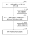
- FIG. 1 is a flowchart illustrating an example of a process for manufacturing a RTB-based sintered magnet according to the present disclosure.
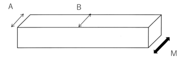
- FIG. 2 is an explanatory diagram illustrating a method for measuring the amount of deformation.
- the present inventors have conducted detailed studies on the causes of oxidation of RTB alloy powders and compacts. As a result, it was found that after producing RTB alloy powders and compacts, oxidation (increase in oxygen concentration) progressed while waiting for the next process after the process in which they were produced.
- the next step after the step of producing the RTB alloy powder is a molding step. Further, the next step after the step of producing the molded body is a sintering step.
- a method can be considered in which, after producing the RTB alloy powder or compact, it is immediately immersed in a solution bath filled with an oil agent for storage.
- the oxygen concentration of the R-T-B alloy powder or compact is not higher than when it is not immersed in the oil, but The oxygen concentration was found to increase during storage. This means that the oxidation of the RTB alloy particles is progressing even during immersion in the oil agent.
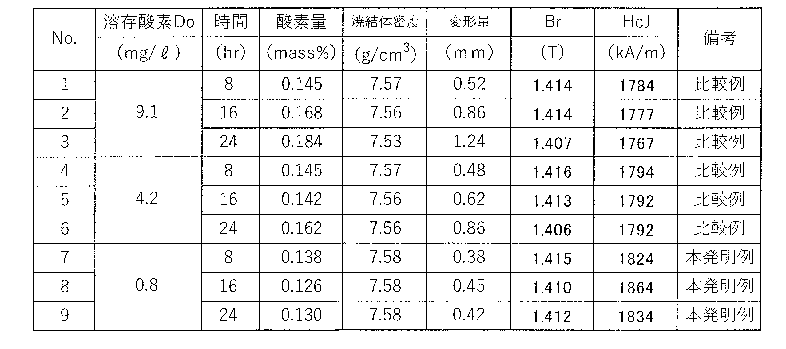
- the inventor found that by setting the amount of dissolved oxygen in the oil in the solution bath to a specific amount or less, the oxygen concentration in the RTB alloy powder and compacts could be increased. We found that it is possible to significantly reduce the Generally, a small amount of oxygen is dissolved in any type of oil.
- the amount of dissolved oxygen is extremely small, and even if the oxidation of the RTB alloy powder or molded body progresses due to the dissolved oxygen, the increase in oxygen concentration will be on the order of several tens of ppm. However, once the oxygen dissolved in the oil is consumed, new oxygen is taken in from the contact surface between the oil and the atmosphere, so oxidation continues and the oxygen in the RTB alloy powder and compact It was found that the concentration increased.
- the progress of oxidation can be suppressed by blocking the contact with oxygen by storing the RTB alloy powder and compacts in a nitrogen atmosphere instead of storing them in an oil solution.
- a nitrogen atmosphere in order to create a nitrogen atmosphere in the entire device, it is necessary to cover the entire device with a stream of nitrogen, making the equipment large and complicated.
- problems arise such as difficulty in handling the equipment itself and poor maintainability.
- the RTB alloy powder or compact is molded and sintered in a short time without storage, the contact with oxygen is short, and therefore it is possible to suppress the progress of oxidation.
- a certain amount of compacts are sintered at one time, so there is inevitably a waiting time until a certain amount of compacts are completed.
- the present inventor considered suppressing the progress of oxidation by reducing the amount of oxygen dissolved in the oil agent.
- the oxidation of the RTB alloy powder and molded body progresses by reducing the amount of dissolved oxygen Do of the oil agent in which the RTB alloy powder and molded body are immersed to 2.5 mg/l or less. It is possible to suppress the decrease in density, decrease in H cJ , and deformation of the sintered body after sintering.
- the oxygen dissolved in the oil depends on the liquid temperature of the oil and the oxygen partial pressure of the atmosphere with which it comes into contact.
- dissolved oxygen can be reduced by lowering the oxygen partial pressure around the oil (solvent) by, for example, inserting a hose into the solvent and introducing nitrogen gas through the hose. According to this method, oxygen can be blocked more easily than in a method of placing the entire apparatus under a nitrogen atmosphere.
- the RTB-based sintered magnet of the present disclosure has, for example, the following composition.
- R 27-35 mass%
- B 0.80 to 1.20 mass%
- Ga 0 to 1.0 mass%
- Cu 0 to 0.5 mass%
- T Contains 60 mass% or more.
- R is a rare earth element and always contains at least one selected from the group consisting of Nd, Pr, and Ce. If R is less than 27 mass%, a liquid phase will not be sufficiently generated during the sintering process, and it may be difficult to sufficiently densify the sintered body. On the other hand, if R exceeds 35 mass%, grain growth may occur during sintering and H cJ may decrease.
- the content of R is preferably 29.5 to 33.0 mass%. If R is within this range, higher B r can be obtained.
- heavy rare earth elements RH such as Tb, Dy, and Ho may be contained.
- B (B:0.80 ⁇ 1.20mass%) If B is less than 0.80 mass%, Br may decrease. On the other hand, if B exceeds 1.20 mass%, H cJ may decrease.
- the content of B is preferably 0.88 to 0.90 mass%. If B is within this range, higher H cJ can be obtained.
- Ga 0 to 1.0 mass%
- the Ga content is preferably 0 to 1.0 mass%, more preferably 0.2 to 0.7 mass%. If Ga is within this range, higher H cJ can be obtained.
- Cu 0 to 0.50 mass%
- the content of Cu is preferably 0 to 0.50 mass%, more preferably 0.05 to 0.30 mass%. If Cu is within this range, higher H cJ can be obtained.
- T 60mass% or more
- T is Fe or Fe and Co.
- the content of T in the sintered magnet is preferably 61.5 to 69.5% by mass. Furthermore, when the total amount of T is 100% by mass, 10% by mass or less may be replaced with Co. For example, 90% by weight of the total amount of T may be Fe and 10% by weight Co. Further, the entire amount of T (100% by mass) may be Fe. Corrosion resistance can be improved by containing Co, but if the amount of Co substitution exceeds 10% by mass of Fe, high Br may not be obtained.
- the RTB-based sintered magnet of the present disclosure may further contain any other element.
- FIG. 1 is a flowchart illustrating an example of a process for manufacturing a RTB-based sintered magnet according to the present disclosure. As shown in the flowchart of FIG.
- the method for manufacturing the RTB-based sintered magnet of the present disclosure includes: ⁇ Crushing step (S10) for producing RTB alloy powder; ⁇ A molding step (S20) of compression molding the RTB alloy powder to produce a compact; ⁇ Includes a sintering step (S30) of sintering the molded body, - Powder storage step (S100) and/or between the crushing step (S10) and the molding step (S20) - A molded body storage step (S200) is included between the molding step (S20) and the sintering step (S30).
- both of the powder storage step (S100) and the compact storage step (S200) may be performed, or only one of them may be performed. That is, the embodiment of the method for manufacturing an RTB-based sintered magnet according to the present disclosure includes a crushing step (S10), a powder storage step (S100), a molding step (S20), and a sintering step (S30).
- the manufacturing method of an RTB-based sintered magnet may include a crushing step (S10), a molding step (S20), a molded body storage step (S200), and a sintering step (S30). ), or may include a pulverization step (S10), a powder storage step (S100), a molding step (S20), and a molded body storage step ( S200) and a sintering step (S30) may be employed.
- RTB alloy powder (2) Grinding process to produce RTB alloy powder Prepare metals or alloys of each element so as to have the target composition, and use strip casting method etc. to Manufacture alloys.
- the obtained RTB alloy is subjected to hydrogen pulverization, and the size of the coarsely pulverized powder is, for example, 1.0 mm or less.
- finely pulverized powder having a median diameter d50 (value obtained by laser diffraction using an air dispersion method) of 2.0 ⁇ m ⁇ d50 ⁇ 8.0 ⁇ m, for example.
- RTB alloy powder is obtained.
- the diameter d50 of the RTB alloy powder is 2.0 ⁇ m ⁇ d50 ⁇ 5.0 ⁇ m.
- the magnetic properties can be further improved.
- the particle size is made smaller, the RTB alloy powder becomes more easily oxidized. Therefore, it is particularly effective to use the method of the present disclosure to suppress oxidation of RTB alloy powder and compacts using the same, which have a diameter d50 in the range of 2.0 ⁇ m ⁇ d50 ⁇ 5.0 ⁇ m.
- a known lubricant may be used as an auxiliary agent in the coarsely pulverized powder before jet mill pulverization, the RTB alloy powder during jet mill pulverization, and after jet mill pulverization.
- d50 can be measured by an air dispersion laser diffraction method (based on JIS Z 8825: 2013 revised edition). That is, in the present disclosure, d50 means a particle size (median diameter) at which the cumulative particle size distribution (volume basis) from the small particle size side is 50%.
- the obtained RTB alloy powder is stored by immersing it in a solution bath containing an oil agent.
- the solution tank refers to a tank containing an oil agent, and the shape and size of the solution tank are not particularly limited. Any shape and size may be used as long as the RTB alloy powder can be immersed therein.
- the oil agent petroleum solvents such as mineral oil and isoparaffin, naphthenic solvents, etc. can be used.
- a characteristic feature of the present disclosure is that in a solution tank in which the RTB alloy powder is immersed, Do ⁇ 2.5 mg/l is satisfied, where Do is the amount of dissolved oxygen in the oil agent in the solution tank. At the point. It is possible to suppress the progress of oxidation of the RTB alloy powder, and it is possible to suppress the decrease in density, decrease in H cj and deformation of the sintered body after sintering. Preferably, the amount of dissolved oxygen in the oil agent in the solution tank satisfies Do ⁇ 1.0 mg/l. It is possible to more reliably suppress the progress of oxidation of the RTB alloy powder.
- a known inert gas such as argon can be used.
- a known method can be used to measure the amount of dissolved oxygen in the oil agent.
- a dissolved oxygen analyzer using a nuclear membrane type galvanic cell type oxygen sensor can be used.
- dissolved oxygen in the solvent may be periodically monitored using an oxygen sensor, and when the amount of dissolved oxygen reaches a reference value (eg, 1.0 mg/l), nitrogen gas may be introduced into the solvent.
- Molding process The RTB alloy powder after the powder storage process is compression molded to produce a molded body. Molding is performed in a magnetic field using RTB alloy powder to obtain a molded body. Molding in a magnetic field is a dry molding method in which dry alloy powder is inserted into the cavity of a mold and molded while applying a magnetic field, and a slurry in which the alloy powder is dispersed is injected into the cavity of the mold. Any known magnetic field molding method may be used, including a wet molding method in which the slurry is molded while discharging the dispersion medium.
- the molded object is stored by immersing it in a solution bath containing an oil agent.
- the shape and size of the solution tank are not particularly limited. Any shape and size that allows the molded body to be immersed may be used.
- the oil agent the same type of solvent as used in the powder storage process described above can be used.
- a characteristic feature of the present disclosure is that in the solution tank in which the molded article is immersed, Do ⁇ 2.5 mg/l is satisfied, where Do is the amount of dissolved oxygen in the oil agent in the solution tank. It is possible to suppress the progress of oxidation of the molded body, and it is possible to suppress the decrease in density, decrease in H cJ , and deformation of the sintered body after sintering.
- the amount of dissolved oxygen in the oil agent in the solution tank satisfies Do ⁇ 1.0 mg/l.
- the progress of oxidation of the molded article can be suppressed more reliably.
- a method for reducing dissolved oxygen in the solvent in the solution bath a method similar to the above-mentioned powder storage process can be used. Note that separate solution tanks or the same solution tank may be used in the powder storage step and the compact storage step. If separate solution vessels are used, different solvents may be used.
- the solution tank used in the powder storage process can be called the first solution tank, and the solution tank used in the compact storage process can be called the second solution tank, but the first solution tank and the second solution tank are of the same structure. It's okay.
- the molded body after the molded body storage process is sintered.
- Sintering of the compact is preferably carried out at a temperature in the range of 950°C to 1150°C.
- residual gases in the atmosphere may be replaced by inert gases such as helium, argon, etc.
- Heat treatment can improve magnetic properties. Heat treatment conditions such as heat treatment temperature and heat treatment time can employ known conditions.
- the thus obtained RTB-based sintered magnet is then subjected to grinding/polishing, surface treatment, magnetization, etc., as necessary, to finally create an RTB-based sintered magnet.
- a crystallized magnet may also be obtained.
- the method for manufacturing an RTB-based sintered magnet of the present disclosure includes an alloy containing a heavy rare earth element RH (RH is at least one of Tb, Dy, and Ho), and an alloy containing R and M ( M is at least one member selected from the group consisting of Ga, Cu, Zn, Al, and Si (RM alloy) is diffused into the interior from the surface of the sintered body. Including further. By diffusing heavy rare earth elements RH, R, M (Ga, Cu, etc.) from the surface of the sintered body into the interior, the coercive force can be efficiently increased.
- RH is at least one of Tb, Dy, and Ho
- M is at least one member selected from the group consisting of Ga, Cu, Zn, Al, and Si
- Dry pulverization was performed in a flowing air to obtain finely pulverized powder (RTB alloy powder) with a particle size D50 of 4.5 ⁇ m.
- the particle size D50 is a volume center value (volume-based median diameter) obtained by a laser diffraction method using an air flow dispersion method.
- the amount of dissolved oxygen in the oil agent was measured using a dissolved oxygen analyzer using a diaphragm type galvanic cell oxygen sensor (organic solvent compatible dissolved oxygen amount meter B-506S manufactured by Iijima Electronics Co., Ltd.).
- a dissolved oxygen analyzer using a diaphragm type galvanic cell oxygen sensor (organic solvent compatible dissolved oxygen amount meter B-506S manufactured by Iijima Electronics Co., Ltd.).
- the finely pulverized powder was stored in an oil solution for 0 to 24 hours while the amount of dissolved oxygen was kept constant.
- the RTB alloy powder was compacted in a magnetic field to obtain a compact.
- the forming apparatus used was a so-called right-angle magnetic field forming apparatus (transverse magnetic field forming apparatus) in which the magnetic field application direction and the pressing direction were perpendicular to each other.
- the obtained compact was sintered at 1050° C. for 4 hours in an Ar flow and then rapidly cooled to obtain an RTB-based sintered magnet.
- Table 1 shows the composition of the RTB sintered magnet (before the diffusion process). The dimensions of the RTB-based sintered magnet were approximately 18 mm in the magnetic field application direction during molding, approximately 10 mm in the pressing direction, and approximately 48 mm in other directions.
- Each of the obtained RTB-based sintered magnets was machined to produce a sample measuring 7.2 mm long, 7.2 mm wide, and 7.2 mm thick.
- the obtained sample was coated with 2.0% by mass of Pr-Ga alloy powder prepared by the atomization method having the composition shown in Table 2 based on 100% by mass of the RTB sintered magnet, and Ar flow gas was applied.
- FIG. 2 is an explanatory diagram illustrating a method for measuring the amount of deformation.
- the amount of deformation was determined by measuring the dimensions of the center part A and end part B in the magnetic field application direction M during molding in the RTB sintered magnet before machining shown in Figure 2, and the difference was taken as the deformation amount. .
- the heat-treated RTB-based sintered magnets (No. 1 to 9) were machined to prepare samples measuring 7.0 mm in length, 7.0 mm in width, and 7.0 mm in thickness. The magnetic properties of each sample were measured by The measurement results are shown in Table 3.
- 0.08% by mass of a hydrocarbon lubricant was added to the obtained coarsely pulverized powder based on 100% by mass of the coarsely pulverized powder, and after mixing, using an air flow pulverizer (jet mill device), Dry pulverization was performed in a nitrogen stream to obtain finely pulverized powder (RTB alloy powder) with a particle size D50 of 3.0 ⁇ m.
- RTB alloy powder finely pulverized powder with a particle size D50 of 3.0 ⁇ m.
- the particle size D50 is the volume center (volume-based median diameter) obtained by a laser diffraction method using an air flow dispersion method.
- a magnetic field was applied. Compression molding was performed in a molded body to obtain a molded product. Note that a so-called right-angle magnetic field forming apparatus (transverse magnetic field forming apparatus) in which the magnetic field application direction and the pressing direction are perpendicular to each other was used as the forming apparatus.
- the obtained molded body was designated as No. Nos. 10 to 13 were left in the atmosphere; Nos. 14 to 22 were immersed in a solution bath containing an oil solution, and the molded bodies were stored in the oil solution.
- a hose was inserted into the solvent, nitrogen gas was introduced through the hose, and the amount of dissolved oxygen in the oil was controlled to 0 to 8.4 mg/l by controlling the flow rate of the introduced nitrogen.
- the compact after storage was sintered at 1040° C. for 4 hours in an Ar flow, and then rapidly cooled to obtain an RTB-based sintered magnet. Table 4 shows the composition of the RTB sintered magnet (before the diffusion process). No.
- Table 4 shows the composition of the RTB sintered magnet (before the diffusion process).
- the amount of oxygen was measured using a gas analyzer based on gas melting/infrared absorption method.
- the amount of deformation was measured by measuring the dimensions of the center and end portions of the sintered magnet, and the difference therebetween was taken as the amount of deformation.
- RTB based sintered magnets Nos. 14 to 22 were machined to prepare samples measuring 7.0 mm in length, 7.0 mm in width, and 7.0 mm in thickness. The magnetic properties of each sample were measured by The measurement results are shown in Table 6.
Landscapes
- Engineering & Computer Science (AREA)
- Power Engineering (AREA)
- Chemical & Material Sciences (AREA)
- Manufacturing & Machinery (AREA)
- Mechanical Engineering (AREA)
- Crystallography & Structural Chemistry (AREA)
- Inorganic Chemistry (AREA)
- Materials Engineering (AREA)
- Metallurgy (AREA)
- Organic Chemistry (AREA)
- Powder Metallurgy (AREA)
- Hard Magnetic Materials (AREA)
Abstract
Description
本開示のR-T-B系焼結磁石は、例えば以下の組成を有する。
R:27~35mass%、
B:0.80~1.20mass%、
Ga:0~1.0mass%、
Cu:0~0.5mass%、
T:60mass%以上を含有する。
Rは希土類元素であり、Nd、PrおよびCeからなる群から選択された少なくとも1つを必ず含む。Rが27mass%未満では焼結過程で液相が十分に生成せず、焼結体を充分に緻密化することが困難になる可能性がある。一方、Rが35mass%を超えると焼結時に粒成長が起こり、HcJが低下する可能性がある。Rの含有量は、好ましくは29.5~33.0mass%である。Rがこのような範囲であれば、より高いBrを得ることができる。RとしてTb、Dy、Ho等の重希土類元素RHを含有してもよい。
Bが0.80mass%未満であると、Brが低下する可能性がある。一方、Bが1.20mass%を超えるとHcJが低下する可能性がある。Bの含有量は、好ましくは0.88~0.90mass%である。Bがこのような範囲であれば、より高いHcJが得られる。
Gaの含有量は、0~1.0mass%が好ましく、より好ましくは、0.2~0.7mass%である。Gaがこのような範囲であれば、より高いHcJが得られる。
Cuの含有量は、0~0.50mass%が好ましく、より好ましくは0.05~0.30mass%である。Cuがこのような範囲であれば、より高いHcJが得られる。
TはFeまたはFeとCoである。
・R-T-B系合金粉末を作製する粉砕工程(S10)と、
・R-T-B系合金粉末を圧縮成形して成形体を作製する成形工程(S20)と、
・成形体を焼結する焼結工程(S30)と、を含み、
・前記粉砕工程(S10)と前記成形工程(S20)の間に粉末保管工程(S100)および/または、
・前記成形工程(S20)と前記焼結工程(S30)の間に成形体保管工程(S200)を含む。
目標組成となるようにそれぞれの元素の金属または合金を準備し、これらに対してストリップキャスティング法等を用いてR-T-B系合金を製造する。得られたR-T-B系合金を水素粉砕し、粗粉砕粉のサイズを例えば1.0mm以下とする。次に、粗粉砕粉をジェットミル等により微粉砕することで、例えばメジアン径d50(気流分散法によるレーザー回折法で得られた値)が2.0μm≦d50≦8.0μmの微粉砕粉(R-T-B系合金粉末)を得る。好ましくは、R-T-B系合金粉末の径d50は、2.0μm≦d50≦5.0μmである。このような範囲にすることにより、より磁気特性を向上させることができる。粒径を小さくするとR-T-B系合金粉末は酸化しやすくなる。よって、径d50が2.0μm≦d50≦5.0μmの範囲にあるR-T-B合金粉末およびそれをもちいた成形体の酸化を抑えるために、本開示の方法を用いることは特に有効である。なお、ジェットミル粉砕前の粗粉砕粉、ジェットミル粉砕中およびジェットミル粉砕後のR-T-B系合金粉末に、助剤として公知の潤滑剤を使用してもよい。d50は、気流分散式レーザー回折法(JIS Z 8825:2013年改訂版に準拠する)により測定することができる。すなわち、本開示において、d50は、小粒径側からの積算粒度分布(体積基準)が50%となる粒径(メジアン径)を意味する。
得られたR-T-B系合金粉末を油剤の入った溶液槽に浸漬して前記R-T-B系合金粉末を保管する。溶液槽は、油剤の入った槽のことをいい、溶液槽の形状や大きさは特に問わない。R-T-B系合金粉末を浸漬することのできる形状・大きさであればよい。油剤は、鉱物油やイソパラフィンに代表される石油系溶剤、ナフテン系溶剤などを使用できる。
粉末保管工程後のR-T-B系合金粉末を圧縮成形して成形体を作製する。R-T-B系合金粉末を用いて磁界中成形を行い、成形体を得る。磁界中成形は、金型のキャビティー内に乾燥した合金粉末を挿入し、磁界を印加しながら成形する乾式成形法、金型のキャビティー内に該合金粉末を分散させたスラリーを注入し、スラリーの分散媒を排出しながら成形する湿式成形法を含む既知の任意の磁界中成形方法を用いてよい。
成形体を油剤の入った溶液槽に浸漬して前記成形体を保管する。溶液槽の形状や大きさは特に問わない。成形体を浸漬することのできる形状・大きさであればよい。油剤は、上述した粉末保管工程で使用するものと同じ種類の溶剤を使用できる。本開示の特徴的な点は、成形体が浸漬された溶液槽において、溶液槽中の油剤の溶存酸素量をDoとしたとき、Do<2.5mg/lを満足する点にある。成形体の酸化が進行するのを抑制でき、焼結後の焼結体の密度低下、HcJの低下および変形を抑制することができる。好ましくは、溶液槽中の油剤の溶存酸素量は、Do<1.0mg/lを満足する。より確実に成形体の酸化の進行を抑制することができる。溶液槽中の溶剤の溶存酸素を低減する方法は、上述した粉末保管工程と同様な方法を用いることができる。なお、粉末保管工程と成形体保管工程とで、別々の溶液漕を用いてもよいし、同一の溶液漕を用いてもよい。別々の溶液漕を用いる場合、異なる溶剤を使用してもよい。粉末保管工程で用いる溶液漕を第1溶液漕、成形体保管工程で用いる溶液漕を第2溶液漕と呼ぶことができるが、第1溶液漕と第2溶液漕とは同一の構造物であってもよい。
成形体保管工程後の成形体を焼結する。成形体の焼結は、好ましくは、温度950℃~1150℃の範囲で行う。焼結による酸化を防止するために、雰囲気の残留ガスは、ヘリウム、アルゴンなどの不活性ガスにより置換され得る。得られた焼結体に対しては、熱処理を行うことが好ましい。熱処理により、磁気特性を向上させることができる。熱処理温度、熱処理時間などの熱処理条件は、公知の条件を採用することができる。こうして得たR-T-B系焼結磁石に対して、必要に応じて、研削・研磨工程、表面処理工程、および着磁工程等を施すことで、最終的にR-T-B系焼結磁石を得ても良い。
R-T-B系焼結磁石がおよそ表1に示す組成となるように、各元素を秤量し、ストリップキャスト法により鋳造し、フレーク状の合金を得た。得られた合金を水素粉砕した後、550℃まで真空中で加熱冷却する脱水素処理を施し、粗粉砕粉を得た。次に得られた粗粉砕紛に、潤滑剤としてステアリン酸亜鉛を粗粉砕粉100質量%に対して0.05質量%添加、混合した後、気流式粉砕機(ジェットミル装置)を用いて窒素流気中で乾式粉砕し粒径D50が4.5μmの微粉砕紛(R-T-B系合金粉末)を得た。なお、粒径D50は気流分散法によるレーザー回折法で得られた体積中心値(体積基準メジアン径)である。


R-T-B系焼結磁石がおよそ表4に示す組成となるように,各元素を秤量し,ストリップキャスト法により鋳造し、フレーク状の合金を得た。得られた合金を水素粉砕した後、550℃まで真空中で加熱冷却する脱水素処理を施して粗粉砕粉を得た。次に、得られた粗粉砕紛に、炭化水素系潤滑剤を粗粉砕粉100質量%に対して0.08質量%添加、混合した後、気流式粉砕機(ジェットミル装置)を用いて、窒素流気中で乾式粉砕し、粒径D50が3.0μmの微粉砕紛(R-T-B系合金粉末)を得た。なお、粒径D50は気流分散法によるレーザー回折法で得られた体積中心地(体積基準メジアン径)である。



Claims (5)
- R-T-B系合金を粉砕してR-T-B系合金粉末(Rは希土類元素であり、Nd、PrおよびCeからなる群から選択された少なくとも1つを必ず含み、TはFeまたはFeとCoであり、Bは硼素である)を作製する粉砕工程と、
前記R-T-B系合金粉末を油剤の入った溶液槽に浸漬して前記R-T-B系合金粉末を保管する粉末保管工程と、
前記粉末保管工程後のR-T-B系合金粉末を圧縮成形して成形体を作製する成形工程と、
前記成形体を焼結する焼結工程と、
を含み、
前記粉末保管工程における、前記溶液槽中の油剤の溶存酸素量をDoとしたとき、Do<2.5mg/lを満足する、
R-T-B系焼結磁石の製造方法。 - Do<1.0mg/lを満足する、請求項1に記載のR-T-B系焼結磁石の製造方法。
- R-T-B系合金粉末(Rは希土類元素であり、Nd、PrおよびCeからなる群から選択された少なくとも1つを必ず含み、TはFeまたはFeとCoであり、Bは硼素である)を圧縮成形して成形体を作製する成形工程と、
前記成形体を油剤の入った溶液槽に浸漬して前記成形体を保管する成形体保管工程と、
前記成形体保管工程後の成形体を焼結する焼結工程と、を含み、
前記成形体保管工程における、溶液槽中の油剤の溶存酸素量をDoとしたとき、Do<2.5mg/lを満足する、
R-T-B系焼結磁石の製造方法。 - Do<1.0mg/lを満足する、請求項3に記載のR-T-B系焼結磁石の製造方法。
- R-T-B系合金を粉砕してR-T-B系合金粉末(Rは希土類元素であり、Nd、PrおよびCeからなる群から選択された少なくとも1つを必ず含み、TはFeまたはFeとCoであり、Bは硼素である)を作製する粉砕工程と、
前記R-T-B系合金粉末を第1油剤の入った第1溶液槽に浸漬して前記R-T-B系合金粉末を保管する粉末保管工程と、
前記粉末保管工程後のR-T-B系合金粉末を圧縮成形して成形体を作製する成形工程と、
前記成形体を第2油剤の入った第2溶液槽に浸漬して前記成形体を保管する成形体保管工程と、
前記成形体保管工程後の成形体を焼結する焼結工程と、を含み、
前記粉末保管工程における前記第1溶液槽中の第1油剤の溶存酸素量、および前記成形体保管工程における前記第2溶液槽中の第1油剤の溶存酸素量は、いずれも2.5mg/l未満である、R-T-B系焼結磁石の製造方法。
Priority Applications (2)
| Application Number | Priority Date | Filing Date | Title |
|---|---|---|---|
| JP2024509867A JPWO2023181771A1 (ja) | 2022-03-24 | 2023-02-22 | |
| CN202380029841.2A CN118974858A (zh) | 2022-03-24 | 2023-02-22 | R-t-b系烧结磁体的制造方法 |
Applications Claiming Priority (2)
| Application Number | Priority Date | Filing Date | Title |
|---|---|---|---|
| JP2022-047885 | 2022-03-24 | ||
| JP2022047885 | 2022-03-24 |
Publications (1)
| Publication Number | Publication Date |
|---|---|
| WO2023181771A1 true WO2023181771A1 (ja) | 2023-09-28 |
Family
ID=88100570
Family Applications (1)
| Application Number | Title | Priority Date | Filing Date |
|---|---|---|---|
| PCT/JP2023/006576 Ceased WO2023181771A1 (ja) | 2022-03-24 | 2023-02-22 | R-t-b系焼結磁石の製造方法 |
Country Status (3)
| Country | Link |
|---|---|
| JP (1) | JPWO2023181771A1 (ja) |
| CN (1) | CN118974858A (ja) |
| WO (1) | WO2023181771A1 (ja) |
Citations (4)
| Publication number | Priority date | Publication date | Assignee | Title |
|---|---|---|---|---|
| JPH0259055A (ja) * | 1988-08-26 | 1990-02-28 | Shin Etsu Chem Co Ltd | 希土類永久磁石合金の湿式粉砕用溶媒 |
| JPH04143206A (ja) * | 1990-10-05 | 1992-05-18 | Seiko Epson Corp | 希土類磁石の製造方法 |
| JPH1097937A (ja) * | 1996-09-20 | 1998-04-14 | Hitachi Metals Ltd | 希土類永久磁石の製造方法 |
| JP2008156739A (ja) * | 2006-12-26 | 2008-07-10 | Sumitomo Metal Mining Co Ltd | ボンド磁石用希土類−鉄−窒素系磁石粉末およびその製造方法 |
-
2023
- 2023-02-22 WO PCT/JP2023/006576 patent/WO2023181771A1/ja not_active Ceased
- 2023-02-22 JP JP2024509867A patent/JPWO2023181771A1/ja active Pending
- 2023-02-22 CN CN202380029841.2A patent/CN118974858A/zh active Pending
Patent Citations (4)
| Publication number | Priority date | Publication date | Assignee | Title |
|---|---|---|---|---|
| JPH0259055A (ja) * | 1988-08-26 | 1990-02-28 | Shin Etsu Chem Co Ltd | 希土類永久磁石合金の湿式粉砕用溶媒 |
| JPH04143206A (ja) * | 1990-10-05 | 1992-05-18 | Seiko Epson Corp | 希土類磁石の製造方法 |
| JPH1097937A (ja) * | 1996-09-20 | 1998-04-14 | Hitachi Metals Ltd | 希土類永久磁石の製造方法 |
| JP2008156739A (ja) * | 2006-12-26 | 2008-07-10 | Sumitomo Metal Mining Co Ltd | ボンド磁石用希土類−鉄−窒素系磁石粉末およびその製造方法 |
Also Published As
| Publication number | Publication date |
|---|---|
| JPWO2023181771A1 (ja) | 2023-09-28 |
| CN118974858A (zh) | 2024-11-15 |
Similar Documents
| Publication | Publication Date | Title |
|---|---|---|
| JP6555170B2 (ja) | R−Fe−B系焼結磁石及びその製造方法 | |
| JP5561170B2 (ja) | R−t−b系焼結磁石の製造方法 | |
| JP6051892B2 (ja) | R−t−b系焼結磁石の製造方法 | |
| WO2013008756A1 (ja) | R-t-b系希土類焼結磁石用合金、r-t-b系希土類焼結磁石用合金の製造方法、r-t-b系希土類焼結磁石用合金材料、r-t-b系希土類焼結磁石、r-t-b系希土類焼結磁石の製造方法およびモーター | |
| JP6521391B2 (ja) | R−t−b系焼結磁石の製造方法 | |
| JP7730311B2 (ja) | R-t-b系永久磁石およびその製造方法、モータおよび自動車 | |
| JP6733398B2 (ja) | R−t−b系焼結磁石の製造方法 | |
| JP2019160949A (ja) | R−t−b系永久磁石 | |
| EP4394810A1 (en) | Sintered r-t-b based magnet | |
| US20250197977A1 (en) | R-t-b sintered magnet | |
| JP7396148B2 (ja) | R-t-b系焼結磁石の製造方法 | |
| US20240321490A1 (en) | R-t-b based permanent magnet | |
| JP7687167B2 (ja) | R-t-b系焼結磁石の製造方法 | |
| CN118692769A (zh) | R-t-b系永久磁铁 | |
| JP6623998B2 (ja) | R−t−b系焼結磁石の製造方法 | |
| CN118974858A (zh) | R-t-b系烧结磁体的制造方法 | |
| JP7831045B2 (ja) | R-t-b系焼結磁石 | |
| US20240363272A1 (en) | R-t-b based sintered magnet | |
| WO2024257745A1 (ja) | 希土類焼結磁石 | |
| EP4704121A1 (en) | R-t-b sintered magnet | |
| WO2025248990A1 (ja) | 希土類焼結磁石及びその製造方法 | |
| JP2024159586A (ja) | R-t-b系焼結磁石 | |
| JP2023139581A (ja) | R-t-b系焼結磁石の製造方法および組成決定方法 | |
| JP2025150315A (ja) | R-t-b系焼結磁石の製造方法、及びr-t-b系焼結磁石 | |
| JP2022133926A (ja) | R-t-b系焼結磁石の製造方法 |
Legal Events
| Date | Code | Title | Description |
|---|---|---|---|
| 121 | Ep: the epo has been informed by wipo that ep was designated in this application |
Ref document number: 23774370 Country of ref document: EP Kind code of ref document: A1 |
|
| ENP | Entry into the national phase |
Ref document number: 2024509867 Country of ref document: JP Kind code of ref document: A |
|
| WWE | Wipo information: entry into national phase |
Ref document number: 202380029841.2 Country of ref document: CN |
|
| NENP | Non-entry into the national phase |
Ref country code: DE |
|
| 122 | Ep: pct application non-entry in european phase |
Ref document number: 23774370 Country of ref document: EP Kind code of ref document: A1 |