WO2023181647A1 - 時計およびバンド - Google Patents
時計およびバンド Download PDFInfo
- Publication number
- WO2023181647A1 WO2023181647A1 PCT/JP2023/003064 JP2023003064W WO2023181647A1 WO 2023181647 A1 WO2023181647 A1 WO 2023181647A1 JP 2023003064 W JP2023003064 W JP 2023003064W WO 2023181647 A1 WO2023181647 A1 WO 2023181647A1
- Authority
- WO
- WIPO (PCT)
- Prior art keywords
- pin
- cover member
- groove
- band
- connecting piece
- Prior art date
Links
- 238000003780 insertion Methods 0.000 claims abstract description 30
- 230000037431 insertion Effects 0.000 claims abstract description 30
- 238000004904 shortening Methods 0.000 claims abstract description 8
- 230000000717 retained effect Effects 0.000 abstract 2
- 230000007423 decrease Effects 0.000 abstract 1
- 230000006866 deterioration Effects 0.000 description 3
- 239000000853 adhesive Substances 0.000 description 2
- 230000001070 adhesive effect Effects 0.000 description 2
- 239000002390 adhesive tape Substances 0.000 description 2
- 238000012986 modification Methods 0.000 description 2
- 230000004048 modification Effects 0.000 description 2
- 239000010453 quartz Substances 0.000 description 1
- VYPSYNLAJGMNEJ-UHFFFAOYSA-N silicon dioxide Inorganic materials O=[Si]=O VYPSYNLAJGMNEJ-UHFFFAOYSA-N 0.000 description 1
- 238000006467 substitution reaction Methods 0.000 description 1
- 210000000707 wrist Anatomy 0.000 description 1
Images


Classifications
-
- A—HUMAN NECESSITIES
- A44—HABERDASHERY; JEWELLERY
- A44C—PERSONAL ADORNMENTS, e.g. JEWELLERY; COINS
- A44C5/00—Bracelets; Wrist-watch straps; Fastenings for bracelets or wrist-watch straps
- A44C5/14—Bracelets; Wrist-watch straps; Fastenings for bracelets or wrist-watch straps characterised by the way of fastening to a wrist-watch or the like
Definitions
- the present invention relates to a watch and a band.
- both ends of a pin also called a spring rod, housed in a connecting piece placed at the end of the band, are held in hole holes formed in the band attachment part of the watch's exterior case.
- the band is connected to the outer case.
- the pin includes a spring and a pair of sliding bodies placed at both ends of the spring and pressed by the springs, and can be expanded and contracted by pressing the sliding bodies against the spring.
- a user who wants to replace the band removes the band from the outer case by shortening the pin and removing both ends from the ring holes.
- Patent Document 1 describes a pin in which a slider is formed with a knob that can be operated from the outside. A user replacing the band can easily shorten the pin by pulling the knob toward the center of the pin.
- the watch and band according to the embodiments improve maintainability and prevent deterioration in appearance quality in a watch whose band can be replaced.
- the watch according to the embodiment includes an exterior case having a pair of band attachment parts in which insertion holes are formed so as to face each other, and ends on both sides inserted into the insertion holes of the pair of band attachment parts.
- a connecting piece that has a pin held in the band attachment part and a groove placed at one end of the band and formed on the bottom, and the groove connects the band to the exterior case by accommodating the pin held in the band attachment part.
- a cover member that covers a groove in which the pin is housed, and the pin has an elastic body that presses the end so that the end can move in parallel in the axial direction.
- An operation part is formed on the side surface of the cover member to receive an operation for moving the end part in parallel toward the center of the pin so that the pin can be removed from the band attachment part.
- the position facing the operating section is opened so that the operating section can be operated from the outside in the state.
- the cover member covers the entire groove in the extending direction, and that the cover member has an opening formed at a position facing the operating section.
- the operating section protrudes from the opening to the outside of the cover member.
- the pin is accommodated in the groove so as to be rotatable in the circumferential direction
- the opening is formed with a notch in the rotational direction of the pin
- the cover member is configured such that the operating portion is located in the notch. It is preferable to restrict the operation of shortening the pin with respect to the operating portion in the state where the pin is located.
- the pin is accommodated in the groove so as to be rotatable in the circumferential direction
- the opening is formed with a notch in the rotational direction of the pin
- the cover member is configured such that the operating portion is located in the notch. It is preferable to restrict the pin from expanding from the shortened state in the housed state.
- the cover member is formed separately from the connecting piece, and has an extending portion extending to a side surface of the connecting piece, and the extending portion has a pin housed in the groove. It is preferable that an insertion hole is formed, and the cover member is held by the connecting piece while covering the groove by inserting a pin into the insertion hole.
- the cover member is coupled to the connecting piece and covers a portion of the groove in the extending direction so as to prevent the pin housed in the groove from falling off.
- the band according to the embodiment includes a pin that is held in the band attachment part by inserting both ends into insertion holes formed in a pair of band attachment parts of the exterior case, and a pin that is arranged at one end of the band and has a bottom surface.
- a connecting piece having a groove formed therein, the connecting piece connecting the band to the exterior case by accommodating the pin held in the band attachment part; and a cover member covering the groove in which the pin is housed;
- the pin has an elastic body that presses the end so that the end can be moved in parallel in the axial direction, and a side surface of the pin has an elastic body that presses the end so that the end can be moved in parallel in the axial direction.
- an operating section is formed that accepts an operation of moving the end portion in parallel toward the center of the pin, and the cover member is attached to the operating section so that the operating section can be operated from the outside with the pin housed in the groove. Open the opposing position.
- FIG. 1 is a perspective view of a timepiece 1.
- FIG. 3 is an exploded perspective view showing the connection relationship between the band attachment part 112 and the connection piece 13.
- FIG. 3 is a perspective view of the connecting piece 13.
- FIG. 3 is a sectional view of the connecting piece 13.
- FIG. 2 is a perspective view of a connecting piece 23; 3 is a perspective view of a connecting piece 33.
- FIG. FIG. 4 is a perspective view of a connecting piece 43;
- FIG. 4 is a cross-sectional view of a connecting piece 43.
- FIG. 1 is a perspective view of a watch 1 according to an embodiment.
- the watch 1 includes a main body 11, a pair of bands 12, and the like.
- the main body 11 is a mechanical watch, a quartz watch, or the like having a timekeeping function.
- the main body 11 includes a pointer, a dial, a movement, etc., and an outer case 111 containing them.
- the exterior case 111 has a pair of band attachment parts 112 on the 12 o'clock side and the 6 o'clock side, respectively, to which bands are attached.
- the pair of bands 12 are formed by connecting a plurality of pieces arranged in a predetermined direction.
- a connecting piece 13 also called an end piece, a tip piece, or a bow tube, which connects the band 12 to the exterior case 111, is arranged.
- One ends of the pair of bands 12 are connected to band attachment portions 112 on the 12 o'clock side and the 6 o'clock side of the exterior case 111 via connection pieces 13, respectively.
- the other ends of the pair of bands 12 are connected to each other via a clasp (not shown), and the band 12 is formed into an annular shape.
- a user wears the watch 1 by passing his or her wrist through the ring-shaped band 12.
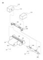
- FIG. 2 is an exploded perspective view showing the connection structure between the connecting piece 13 and the band attachment part 112
- FIG. 3 is a perspective view of the connecting piece 13
- FIG. 4 is a state in which the band 12 is attached to the band attachment part 112. It is a sectional view of connection piece 13 in . 2 to 4 are illustrated with the bottom surface (lower surface in FIG. 1) of the connecting piece 13 facing upward.
- FIG. 4 is a sectional view taken along the line IV-IV in FIG. 3.
- the pair of band attachment parts 112 are formed with insertion holes 113, also called ring holes, so as to face each other.
- the pin 14 is held in the band attachment part 112 by having both ends inserted into the pair of insertion holes 113, respectively.
- the connecting piece 13 connects the band 12 to the exterior case 111 by accommodating the pin 14 held by the band attaching part 112 in a groove 131 on the bottom surface.
- the cover member 15 covers the groove 131 in which the pin 14 is accommodated.
- the pin 14 includes a cylindrical body 141, an elastic body 142 built into the cylindrical body 141, and an axis of the cylindrical body 141. It has a pair of sliding bodies 143 that can be moved in parallel in the direction.
- the cylindrical body 141 is formed into a cylindrical shape.
- First openings 144 are formed in both end surfaces of the cylindrical body 141, respectively.
- a pair of second openings 145 extending in the axial direction are formed on the side surface of the cylindrical body 141 .
- Each of the sliding bodies 143 is formed with an end portion 146 that projects from the first opening 144 to the outside of the cylindrical body 141 .
- the pin 14 is held in the band attachment part 112 by inserting the ends 146 of the pin 14 into the insertion holes 113 of the band attachment part 112.
- the elastic body 142 is a coil spring.
- the elastic body 142 contacts a pair of sliding bodies 143 at both ends, and presses the sliding bodies 143 so that the end portions 146 can move in parallel in the axial direction.
- each of the sliding bodies 143 is formed with an operating portion 147 that protrudes from the second opening 145 to the outside of the cylindrical body 141 . By pulling the operating portions 147 toward the center of the pin 14 in the axial direction, the end portion 146 is moved in parallel toward the center of the pin 14, shortening the pin 14, and removing the pin 14 from the band attachment portion 112. It becomes possible.
- a groove 131 (see FIG. 2) for accommodating the pin 14 is formed on the bottom surface of the connecting piece 13.
- the groove portion 131 extends from one end of the bottom surface of the connecting piece 13 in the axial direction of the pin 14 to the other end so that the pin 14 can be inserted from the side surface of the connecting piece 13.
- the groove portion 131 is formed so that its maximum width is the same as the outer diameter of the cylindrical body 141 of the pin 14 or slightly larger than the outer diameter of the cylindrical body 141.
- a narrow portion 132 is formed at the connection portion between the groove portion 131 and the bottom surface of the connecting piece 13 so that the width of the groove portion 131 is partially smaller than the outer diameter of the cylindrical body 141. Thereby, the pin 14 is accommodated in the groove 131 without falling off.
- the operating portion 147 extends from between the narrowed portions 132 and can be operated from the outside. Further, since the cylindrical body 141 is formed in a cylindrical shape, the pin 14 can rotate in the circumferential direction while being accommodated in the groove 131 within a range where the operating portion 147 does not come into contact with the narrowed portion 132.
- the cover member 15 is a member that covers the groove portion 131, and is formed separately from the connection piece 13.
- the cover member 15 is a flat member extending in the extending direction of the groove 131 so as to cover the groove 131 from one end to the other end in the extending direction, that is, to cover the entire groove 131 in the extending direction.
- the cover member 15 opens a position facing the operating portion 147 so that the operating portion 147 can be operated from the outside with the groove portion 131 covered by the cover member 15.
- rectangular openings 151 extending in the sliding direction of the operating section 147 are formed in positions facing the operating section 147 of the cover member 15, so that the operating section 147 The opposing position is open, and the operating section 147 can be operated from the outside.
- the operating portion 147 is formed to have such a length that it protrudes from the opening 151 to the outside of the cover member 15 while the groove portion 131 in which the pin 14 is accommodated is covered by the cover member 15. This allows the user to grasp and operate the portion of the operating section 147 that protrudes from the cover member 15 with his or her fingers.
- the cover member 15 has extending portions 152 at both ends in the extending direction that extend to the side surfaces of the connecting piece 13 so as to cover both ends of the groove portion 131.
- the extension portion 152 is formed with an insertion hole 153 through which the end portion 146 of the pin 14 accommodated in the groove portion 131 is inserted. By inserting the end portion 146 into the insertion hole 153, the cover member 15 is held by the connecting piece 13 while covering the groove portion 131.
- the narrowed portion 132 of the groove portion 131 is recessed by a distance corresponding to the thickness of the cover member 15 with respect to the bottom and side surfaces of the connecting piece 13.
- a connecting portion 16 that connects the connecting piece 13 with a piece of the band 12 is formed at the end of the connecting piece 13 on the band 12 side.
- the connecting portion 16 has a through hole 161 passing through a pair of side surfaces. With a connecting pin (not shown) inserted into the through hole 161, both ends of the connecting pin are held by pieces of the band 12, thereby connecting the connecting piece 13 with the band 12.
- the pin 14 When attaching the band 12 to the exterior case 111, the pin 14 is first accommodated in the groove 131.
- the pin 14 is accommodated in the groove 131 of the connecting piece 13 from the side surface of the connecting piece 13 connected to the band 12 .
- the cover member 15 is placed so as to cover the groove 131 in which the pin 14 is accommodated.
- the cover member 15 is placed above the groove 131 so that the tip of the operating section 147 protrudes from the opening 151 when the operating section 147 is not operated.
- the tip of the extending portion 152 interferes with the end portion 146 of the pin 14, both ends of the groove portion 131 are not covered by the extending portion 152 and are open.
- the user grasps the tips of the operating parts 147 protruding from the opening 151 and draws the operating parts 147 toward each other.
- the pin 14 is shortened until the tip of the end portion 146 is located inside the extension portion 152 in the axial direction, and the tip of the extension portion 152 no longer interferes with the end portion 146.
- the extending portion 152 is inserted to a position covering both ends of the groove portion 131. Thereby, the groove portion 131 is covered by the cover member 15.
- the cover member 15 After the groove portion 131 is covered by the cover member 15, the user releases the operating portion 147. As a result, the pin 14 is extended, and the end portion 146 is inserted into the insertion hole 153. In this way, the cover member 15 is held on the connecting piece 13 while covering the groove portion 131.
- the connecting piece 13 is connected to the band attachment part 112.
- the user grasps the operation parts 147 and pulls them toward each other.
- the pin is shortened until the tip of the end portion 146 is located inside the extension portion 152.
- the connecting piece 13 is placed between the pair of band attachment parts 112 of the exterior case 111.
- the pin 14 expands, and the end portion 146 is inserted into the insertion hole 153 and inserted into the insertion hole 113 of the band attachment portion 112. In this way, the pin 14 is held by the band attachment part 112, and the band 12 is attached to the outer case 111.
- the user grasps the operating parts 147 and pulls them toward each other. As a result, the pin 14 is shortened until the tip of the end portion 146 comes out of the insertion hole 113. In this state, the connecting piece 13 is removed from between the band attachment parts 112, and the band 12 is removed from the outer case 111.
- the user releases the operating part 147.
- the pin 14 expands and the end portion 146 is inserted into the insertion hole 153 again.
- the cover member 15 is held on the connecting piece 13 while covering the groove 131. Therefore, even when the band 12 is not attached to the outer case 111, the pin 14 is prevented from falling out of the groove 131, and the possibility of losing the pin 14 is reduced.
- the cover member 15 is removed first.
- the user grasps the tips of the operating parts 147 and pulls them toward each other.
- the pin is shortened until the tip of the end portion 146 is located inside the extension portion 152.
- the cover member 15 is pulled up until the insertion hole 153 moves to a position where it does not oppose the end portion 146 of the pin 14.
- the user releases the tip of the operating section 147 to release the operation on the operating section 147.
- the cover member 15 is further pulled up and removed from the groove portion 131. In this way, the cover member 15 is removed from the connecting piece 13.
- the pin 14 is removed from the groove 131.
- the pin 14 is removed by being pulled out laterally from the groove 131. In this way, the pin 14 can be easily removed from the connecting piece 13 without using a special tool, so even if the pin 14 is damaged, it can be easily replaced, improving maintainability.
- the watch 1 includes the outer case 111, the pin 14, the connecting piece 13, and the cover member 15.
- the exterior case 111 has a pair of band attachment parts 112 in which insertion holes 113 are formed so as to face each other.
- the pin 14 is formed to be expandable and retractable by a built-in elastic body 142, and is held by the band attachment portions 112 by having both ends inserted into the insertion holes 113 of the pair of band attachment portions 112, respectively.
- the connecting piece 13 is arranged at one end of the band 12, and a groove 131 is formed on the bottom surface.
- the connecting piece 13 connects the band 12 to the exterior case 111 by accommodating the pin 14 held by the band attaching part 112 in the groove part 131 .
- an operating portion 147 is formed on the side surface of the pin 14 to accept an operation for shortening the pin 14 so that the pin 14 can be removed from the band attachment portion 112.
- the cover member 15 has a position facing the operating section 147 open so that the operating section 147 can be operated from the outside with the pin 14 housed in the groove 131.
- the watch 1 is a watch with a replaceable band that can improve maintainability and prevent deterioration in appearance quality.
- the cover member 15 covers the entire groove portion 131 in the extending direction.
- An opening is formed in the cover member 15 at a position facing the operating section 147. As a result, the entire groove portion 131 is no longer visible from below, improving the appearance quality.
- the operating portion 147 protrudes from the opening 151 to the outside of the cover member 15. This allows the user to grasp and operate the operating section 147 with his or her fingers, making it easier to remove the band 12.
- the cover member 15 is formed separately from the connection piece 13 and has an extension portion 152 that extends to the side surface of the connection piece 13.
- the extending portion 152 is formed with an insertion hole 153 into which the pin 14 accommodated in the groove portion 131 is inserted.
- the cover member 15 is held by the connecting piece 13 while covering the groove portion 131 by inserting the pin 14 into the insertion hole 153 . Thereby, the groove portion 131 is no longer visible from the side, and the appearance quality is further improved.
- the operating portion 147 was assumed to protrude from the opening 151 to the outside of the cover member 15, but the present invention is not limited to such an example.
- the operating portion 147 may be formed in such a length that it does not protrude outside the cover member 15. That is, the operating portion 147 may be formed shorter than the distance between the pin 14 and the opening 151 of the cover member 15.
- the user can insert a tool such as tweezers into the opening 151 to operate the operating section 147 and remove the band 12.
- the operating section 147 is less likely to be visually recognized from the outside, so that the appearance quality is further improved.
- FIG. 5 is a perspective view of a connecting piece 23 of a watch according to another embodiment.
- the connection piece 23 differs from the connection piece 13 in that it has a cover member 25 instead of the cover member 15.
- the cover member 25 differs from the cover member 15 in that an opening 251 is formed instead of the opening 151.
- the other configurations of the cover member 25 are the same as the corresponding configurations of the cover member 15, so the same reference numerals are given and the explanation will be omitted.
- the opening 251 is formed in a rectangular shape extending in the sliding direction of the operating section 147, and a notch 254 is formed at the position of the operating section 147 when it is not operated.
- the cutout portion 254 is formed in a direction perpendicular to the rotating direction of the pin 14 accommodated in the groove portion 131, that is, the extending direction of the pin 14.
- the cutout portion 254 is formed in the same direction for each of the plurality of openings 251.
- the operating portion 147 when not being operated, the operating portion 147 is located at the outer end of the rectangle of the opening 251 in the axial direction of the pin 14. Therefore, the notch 254 is formed at the outer end of the rectangle, and the opening 251 is formed in an L shape.
- the user rotates the pin 14 housed in the groove 131 in the circumferential direction (direction A in FIG. 5).
- the operating section 147 is accommodated in the notch 254.
- the operating portion 147 accommodated in the notch 254 interferes with the cover member 25 and cannot move toward the center of the pin 14 in the axial direction. That is, the cover member 25 restricts the operation of shortening the pin 14 by drawing the operating parts 147 toward each other when the operating parts 147 are housed in the notch 254 .
- the pin 14 is accommodated in the groove 131 so as to be rotatable in the circumferential direction.
- a notch 254 is formed in the opening 251 of the cover member 25 in the direction in which the pin 14 rotates.
- the cover member 25 restricts the operation of shortening the pin 14 relative to the operating portion 147 when the operating portion 147 is housed in the notch 254 . This prevents the band 12 from detaching from the outer case 111 due to the operation of the operating section 147 while the user is using the watch 1.
- FIG. 6 is a perspective view of a connecting piece 33 of a timepiece according to another embodiment.
- the connection piece 33 differs from the connection piece 13 in that it has a cover member 35 instead of the cover member 15.
- the cover member 35 differs from the cover member 15 in that an opening 351 is formed instead of the opening 151.
- the other configurations of the cover member 35 are the same as the corresponding configurations of the cover member 15, so the same reference numerals are given and the explanation will be omitted.
- the opening 351 is formed in a rectangular shape extending in the sliding direction of the operating section 147, and a notch 354 is formed at the position of the operating section 147 when the pin 14 is shortened.
- the cutout portion 354 is formed in a direction perpendicular to the rotating direction of the pin 14 accommodated in the groove portion 131, that is, the extending direction of the pin 14.
- the cutout portion 354 is formed in the same direction for each of the plurality of openings 351.
- the notch 354 is formed at the inner end of the rectangle, which is the position when the pin 14 is shortened, and the opening 351 is formed in an L-shape.
- the user grasps the tips of the operating parts 147 protruding from the opening 351, draws the operating parts 147 toward each other, and rotates the pin 14 in the circumferential direction A.
- the end portion 146 moves in parallel toward the center in the axial direction until the tip of the end portion 146 is located inside the extension portion 152, and the pin 14 is shortened. be accommodated in.
- the operating section 147 accommodated in the notch 354 interferes with the cover member 35 and cannot move toward the outside in the axial direction of the pin 14 .
- the cover member 35 prevents the pin 14 from expanding in a state where the operating portion 147 is accommodated in the notch 354. Therefore, even if the user removes his/her hand from the operating section 147, the pin 14 remains in the shortened state.
- the extending portion 152 of the cover member 35 is inserted to a position covering both ends of the groove portion 131.
- the groove portion 131 is covered by the cover member 35.
- the cover member 35 can be easily attached.
- the connecting piece 33 is connected to the band attaching part 112
- the connecting piece 13 is placed between the pair of band attaching parts 112 of the exterior case 111 while the operating part 147 is housed in the notch 354. Ru.
- the user rotates the pin 14 in the circumferential direction B.
- the operating portion 147 is detached from the cutout portion 354, and the end portion 146 is translated in a direction away from the center of the pin 14 in the axial direction and is inserted into the insertion hole 153. inserted into.
- the pin 14 is held by the band attachment part 112, and the band 12 is attached to the band attachment part 112.
- the pin 14 is accommodated in the groove 131 so as to be rotatable in the circumferential direction.
- a notch 354 is formed in the opening 351 of the cover member 35 in the direction in which the pin 14 rotates.
- the cover member 35 restricts the pin 14 from expanding in a state where the operating portion 147 is housed in the notch 354. This allows the pin 14 to maintain its shortened state even if the user takes his hand off the operating section 147, making it easier to replace the band.
- cutouts may be formed at both the position of the operating part 147 when it is not operated and the position of the operating part 147 when the pin 14 is shortened.
- the shapes of the openings are not limited to the examples of the openings 151, 251, and 351 described above.
- the cover member may be formed with an opening having any shape, such as an oval shape or a cross shape, which allows the operating portion 147 to be operated from the outside.
- FIG. 7 is a perspective view of a connecting piece 43 of a timepiece according to another embodiment
- FIG. 8 is a sectional view of the connecting piece 43.
- FIG. 8 is a cross-sectional view similar to FIG. 4.
- the connecting piece 43 differs from the connecting piece 13 in that it has a pin 44 and a cover member 45 instead of the pin 14 and the cover member 15.
- the other configurations of the connecting piece 43 are similar to the corresponding configurations of the connecting piece 13, so the same reference numerals are given and the explanation will be omitted.
- the pin 44 includes a cylindrical body 141, an elastic body 142 built into the cylindrical body 141, a first sliding body 443, and a second sliding body 448.
- the first sliding body 443 contacts one end of the elastic body 142.
- the first sliding body 443 is formed with an end portion 146 that projects from the first opening 144 to the outside of the cylindrical body 141, and also extends from the second opening 145 to the outside of the cylindrical body 141.
- a protruding operating portion 147 is formed.
- the second sliding body 448 abuts the other end of the elastic body 142.
- the second sliding body 448 is formed with an end portion 146 that projects from the first opening 144 to the outside of the cylindrical body 141 , and a recessed portion 449 is formed so as to face the second opening 145 .
- the operating section 447 fits into the recess 449.
- the recessed portion 449 and the operating portion 447 are fitted together by screwing together using a screw structure.
- the cover member 45 is formed coupled to the connecting piece 43. In the example shown in FIG. 7, the cover member 45 is formed integrally with the connection piece 43. The cover member 45 covers a portion of the groove portion 131 in the extending direction. In the example shown in FIGS. 7 and 8, the cover member 45 covers the space between the operating portion 147 and the operating portion 447 of the groove portion 131, leaving the positions of the operating portion 147 and the operating portion 447 open.
- the operating portion 147 is formed to have a length such that the upper end of the operating portion 147 is higher than the lower end of the cover member 45 when the pin 14 is housed in the groove 131.
- the operating portion 447 is formed to a length such that the upper end of the operating portion 447 is higher than the lower end of the cover member 45 when the pin 14 is accommodated in the groove 131 and the operating portion 447 is fitted into the recess 449. Ru.
- the operating portion 147 or 447 interferes with the cover member 45, so that the pin 14 is prevented from falling out of the groove 131.
- the pin 44 with the operation part 447 removed is accommodated in the groove 131 of the connection piece 43 from the side surface of the connection piece 43.
- the pin 44 is accommodated in the groove 131 from the side where the second sliding body 448 is disposed, as shown in direction C in FIG.
- the operating portion 447 is fitted into the recess 449.
- the operating parts 147 and 447 are operated to shorten the pin 44, and the connecting piece 43 is placed between the pair of band attachment parts 112 of the exterior case 111. .
- the cover member 45 is coupled to the connecting piece 43 and covers a portion of the groove 131 in the extending direction so as to prevent the pin 44 housed in the groove 131 from falling out of the groove 131. This eliminates the need to use a separate cover member, so the appearance quality is improved with a reduced number of parts, and the pin 44 is prevented from falling out of the groove 131.
- the operating portion 447 is fitted into the recessed portion 449 by screwing, but the present invention is not limited to such an example.
- the operating portion 447 may be fitted into the recess 449 via adhesive, adhesive tape, or the like.
- cover member 45 is formed integrally with the connecting piece 43, but the present invention is not limited to such an example.
- Cover member 45 may be coupled to cover member 45 in any manner such that it cannot be removed by a user.
- the cover member 45 may be bonded to the connecting piece 43 using an adhesive, adhesive tape, or the like.
Landscapes
- Electric Clocks (AREA)
Abstract
実施形態に係る時計は、バンドの交換が可能な時計において、保守性を向上させ、かつ外観品質の低下を防止することを可能とする。実施形態に係る時計は、相互に対向するように挿入孔が形成された一対のバンド取付部を有する外装ケースと、内蔵される弾性体により伸縮可能に形成され、両端が一対のバンド取付部の挿入孔に挿入されることによりバンド取付部に保持されるピンと、バンドの一端に配置され、底面に溝部が形成された接続駒であって、溝部がバンド取付部に保持されたピンを収容することによりバンドを外装ケースに接続する接続駒と、ピンが収容された溝部を覆うカバー部材と、を有し、ピンの側面には、ピンがバンド取付部から取外し可能となるようにピンの両端を短縮する操作を受け付ける操作部が形成され、カバー部材は、ピンが溝部に収容された状態で操作部を外部から操作可能となるように、操作部に対向する位置を開放する。
Description
本発明は、時計およびバンドに関する。
従来、バンドを交換可能な時計が知られている。このような時計においては、バンドの端部に配置された接続駒に収容された、ばね棒とも称されるピンの両端が、時計の外装ケースのバンド取付部に形成されたカン穴に保持されることにより、バンドが外装ケースに接続される。ピンはばねとばねの両端に配置されてばねにそれぞれ押圧される一対の摺動体とを内蔵し、摺動体をばねに抗して押圧することにより伸縮可能である。バンドを交換する利用者は、ピンを短縮して両端をカン穴から取り外すことにより、バンドを外装ケースから取り外す。
特許文献1には、摺動体に外部から操作可能なつまみをそれぞれ形成したピンが記載されている。バンドを交換する利用者は、つまみをピンの中央に引き寄せることにより、簡易にピンを短縮することができる。
上述したようなピンの交換を容易にして保守性を向上させるために、このようなピンはバンドの接続駒の底面に形成された溝部に収容されることがある。しかしながら、この場合、ピンが下方から視認され、外観品質が低下するという問題点があった。
実施形態に係る時計およびバンドは、バンドの交換が可能な時計において、保守性を向上させ、かつ外観品質の低下を防止することを可能とする。
実施形態に係る時計は、相互に対向するように挿入孔が形成された一対のバンド取付部を有する外装ケースと、両側の端部が一対のバンド取付部の挿入孔にそれぞれ挿入されることによりバンド取付部に保持されるピンと、バンドの一端に配置され、底面に溝部が形成された接続駒であって、溝部がバンド取付部に保持されたピンを収容することによりバンドを外装ケースに接続する接続駒と、ピンが収容された溝部を覆うカバー部材と、を有し、ピンは、端部が軸方向に平行移動可能となるように、端部を押圧する弾性体を有し、ピンの側面には、ピンがバンド取付部から取外し可能となるように、端部をピンの中央に向かって平行移動させる操作を受け付ける操作部が形成され、カバー部材は、ピンが溝部に収容された状態で操作部を外部から操作可能となるように、操作部に対向する位置を開放する。
また、実施形態に係る時計において、カバー部材は、溝部の延伸方向における全部を覆い、カバー部材には、操作部に対向する位置に開口が形成されることが好ましい。
また、実施形態に係る時計において、操作部は、開口からカバー部材の外側に突出することが好ましい。
また、実施形態に係る時計において、ピンは、周方向に回動可能に溝部に収容され、開口には、ピンの回動方向に切欠部が形成され、カバー部材は、操作部が切欠部に位置する状態で、操作部に対するピンを短縮する操作を規制することが好ましい。
また、実施形態に係る時計において、ピンは、周方向に回動可能に溝部に収容され、開口には、ピンの回動方向に切欠部が形成され、カバー部材は、操作部が切欠部に収容された状態で、ピンが短縮された状態から伸長することを規制することが好ましい。
また、実施形態に係る時計において、カバー部材は、接続駒とは別体として形成され、接続駒の側面に延出する延出部を有し、延出部には、溝部に収容されたピンが挿通される挿通孔が形成され、カバー部材は、挿通孔にピンが挿通されることにより、溝部を覆った状態で接続駒に保持されることが好ましい。
また、実施形態に係る時計において、カバー部材は、接続駒に結合され、溝部に収容されたピンが脱落することを規制するように、溝部の延伸方向における一部を覆うことが好ましい。
実施形態に係るバンドは、外装ケースが有する一対のバンド取付部に形成された挿入孔に両側の端部が挿入されることによりバンド取付部に保持されるピンと、バンドの一端に配置され、底面に溝部が形成された接続駒であって、溝部がバンド取付部に保持されたピンを収容することによりバンドを外装ケースに接続する接続駒と、ピンが収容された溝部を覆うカバー部材と、を有し、ピンは、端部が軸方向に平行移動可能となるように、端部を押圧する弾性体を有し、ピンの側面には、ピンがバンド取付部から取外し可能となるように、端部をピンの中央に向かって平行移動させる操作を受け付ける操作部が形成され、カバー部材は、ピンが溝部に収容された状態で操作部を外部から操作可能となるように、操作部に対向する位置を開放する。
本発明の目的および効果は、特に請求項に記載される構成要素およびその組み合わせを用いることによって認識され、および達成される。前述の一般的な説明および後述の詳細な説明の両方は、例示的かつ説明的なものであり、特許請求の範囲に記載されている発明を限定するものではない。
以下、図面を参照しつつ、本発明の様々な実施形態について説明する。本発明の技術的範囲はそれらの実施形態に限定されず、特許請求の範囲に記載された発明およびその均等物に及ぶ点に留意されたい。
図1は、実施形態に係る時計1の斜視図である。時計1は、本体部11、一対のバンド12等を有する。
本体部11は、計時機能を有する機械式時計、クォーツ式時計等である。本体部11は、指針、文字板、ムーブメント等およびそれらを内蔵する外装ケース111を有する。外装ケース111は、12時側および6時側に、バンドが取り付けられる一対のバンド取付部112をそれぞれ有する。
一対のバンド12は、所定方向に配列された複数の駒が連結されて形成される。一対のバンド12の一端には、バンド12を外装ケース111に接続する、エンドピース、先カンまたは弓管とも称される接続駒13がそれぞれ配置される。一対のバンド12の一端は、接続駒13を介して外装ケース111の12時側および6時側のバンド取付部112にそれぞれ接続される。一対のバンド12の他端は、不図示の中留めを介して相互に接続され、バンド12が環状に形成される。利用者は、環状に形成されたバンド12に腕等を通すことで、時計1を装着する。
図2は接続駒13とバンド取付部112との接続構造を示す分解斜視図であり、図3は接続駒13の斜視図であり、図4はバンド12がバンド取付部112に取り付けられた状態における接続駒13の断面図である。図2-図4は、接続駒13の底面(図1における下側の面)が上側となるように図示されている。図4は、図3のIV-IV断面の断面図である。
図2に示すように、一対のバンド取付部112には、相互に対向するようにカン穴とも称される挿入孔113が形成される。ピン14は、両端が一対の挿入孔113にそれぞれ挿入されることにより、バンド取付部112に保持される。接続駒13は、底面の溝部131がバンド取付部112に保持されたピン14を収容することにより、バンド12を外装ケース111に接続する。カバー部材15は、ピン14が収容された溝部131を覆う。
図4に示すように、ピン14は、筒状体141、筒状体141に内蔵される弾性体142、および弾性体142を挟むように筒状体141に内蔵され、筒状体141の軸方向に平行移動可能な一対の摺動体143を有する。
筒状体141は、円筒状に形成される。筒状体141の両端面には、第1開口144がそれぞれ形成される。筒状体141の側面には、軸方向に延伸する一対の第2開口145が形成される。摺動体143のそれぞれには、第1開口144から筒状体141の外部に突出する端部146が形成される。ピン14の両側の端部146がバンド取付部112の挿入孔113に挿入されることにより、ピン14がバンド取付部112に保持される。
弾性体142はコイルばねである。弾性体142は、両端において一対の摺動体143とそれぞれ当接し、端部146が軸方向に平行移動可能となるように摺動体143を押圧する。また、摺動体143のそれぞれには、第2開口145から筒状体141の外部に突出する操作部147が形成される。操作部147をピン14の軸方向における中央に向けて相互に引き寄せる操作により、端部146がピン14の中央に向かって平行移動されてピン14が短縮され、ピン14がバンド取付部112から取外し可能となる。
接続駒13の底面には、ピン14を収容する溝部131(図2参照)が形成される。溝部131は、ピン14を接続駒13の側面から挿入可能となるように、接続駒13の底面の、ピン14の軸方向における一端から他端にわたって延伸する。溝部131は、最大幅がピン14の筒状体141の外径と同一になるように、または筒状体141の外径よりもわずかに大きくなるように形成される。溝部131と接続駒13の底面との接続部分には、溝部131の幅が部分的に筒状体141の外径よりも小さくなるように狭窄部132が形成される。これにより、ピン14は、脱落することなく溝部131に収容される。
ピン14が溝部131に収容された状態で、操作部147は狭窄部132の間から延出し、外部から操作可能である。また、筒状体141が円筒状に形成されるため、ピン14は、溝部131に収容された状態で、操作部147が狭窄部132と接触しない範囲で周方向に回動可能である。
カバー部材15は、溝部131を覆う部材であり、接続駒13とは別体として形成される。カバー部材15は、溝部131をその延伸方向の一端から他端にわたって覆うように、すなわち溝部131の延伸方向における全部を覆うように、溝部131の延伸方向に延伸する平板状の部材である。
カバー部材15は、溝部131がカバー部材15に覆われた状態で操作部147を外部から操作可能となるように、操作部147に対向する位置を開放する。図3および図4に示す例では、カバー部材15の操作部147に対向する位置に、操作部147の摺動方向に延伸する矩形状の開口151がそれぞれ形成されることにより、操作部147に対向する位置が開放され、操作部147が外部から操作可能となっている。カバー部材15が溝部131を覆うことにより、溝部131が下方から視認されなくなり、外観品質の低下が防止される。
操作部147は、ピン14が収容された溝部131がカバー部材15に覆われた状態で、開口151からカバー部材15の外側に突出するような長さに形成される。これにより、利用者が操作部147のカバー部材15から突出した部分を指で把持して操作することが可能となる。
カバー部材15は、その延伸方向における両端に、溝部131の両端を覆うように接続駒13の側面に延出する延出部152を有する。延出部152には、溝部131に収容されたピン14の端部146が挿通される挿通孔153が形成される。挿通孔153に端部146が挿通されることにより、カバー部材15は、溝部131を覆った状態で接続駒13に保持される。
溝部131の狭窄部132は、接続駒13の底面および側面に対して、カバー部材15の厚さに相当する距離だけ窪んで形成される。これにより、カバー部材15が溝部131を覆った状態で、カバー部材15が接続駒13の底面および側面とそれぞれ同一平面を形成するため、外観品質が向上する。
接続駒13のバンド12の側の端部には、接続駒13をバンド12の駒と連結する連結部16が形成される。連結部16は、一対の側面を貫通する貫通孔161を有する。貫通孔161に不図示の連結ピンが挿通された状態で、連結ピンの両端がバンド12の駒によって保持されることにより、接続駒13がバンド12と連結される。
バンド12を外装ケース111に取り付けるときには、最初に、ピン14が溝部131に収容される。ピン14は、バンド12と連結された接続駒13の側面から接続駒13の溝部131に収容される。
次に、ピン14が収容された溝部131を覆うようにカバー部材15が配置される。まず、操作部147が操作されていない状態で、操作部147の先端が開口151から突出するように、カバー部材15が溝部131の上方に配置される。この状態では、延出部152の先端がピン14の端部146と干渉するため、溝部131の両端は延出部152に覆われることなく開放されている。
次に、利用者は、開口151から突出した操作部147の先端を把持して、操作部147を相互に引き寄せる。これにより、端部146の先端が延出部152よりも軸方向の内側に位置するまでピン14が短縮され、延出部152の先端が端部146と干渉しなくなる。この状態を維持したまま、延出部152が溝部131の両端を覆う位置まで挿入される。これにより、溝部131がカバー部材15によって覆われる。
溝部131がカバー部材15によって覆われた後、利用者は、操作部147から手を離す。これにより、ピン14が伸長し、端部146は挿通孔153に挿通される。このようにして、カバー部材15が溝部131を覆った状態で接続駒13に保持される。
次に、接続駒13がバンド取付部112に接続される。利用者は、操作部147を把持して相互に引き寄せる。これにより、端部146の先端が延出部152よりも内側に位置するまでピンが短縮される。この状態を維持したまま、接続駒13が外装ケース111の一対のバンド取付部112の間に配置される。
接続駒13がバンド取付部112の間に配置された後、利用者は、操作部147から手を離す。これにより、ピン14が伸長し、端部146は挿通孔153に挿通されるとともに、バンド取付部112の挿入孔113に挿入される。このようにして、ピン14がバンド取付部112に保持され、バンド12が外装ケース111に取り付けられる。
バンド12を外装ケース111から取り外すときには、利用者は、操作部147を把持して相互に引き寄せる。これにより、端部146の先端が挿入孔113から抜けるまでピン14が短縮される。この状態で、接続駒13がバンド取付部112の間から取り除かれ、バンド12が外装ケース111から取り外される。
接続駒13がバンド取付部112の間から取り除かれた後、利用者は、操作部147から手を離す。これにより、ピン14が伸長し、端部146は挿通孔153に再び挿通される。このようにして、バンド12が取り外された後も、カバー部材15が溝部131を覆った状態で接続駒13に保持される。したがって、バンド12が外装ケース111に取り付けられていない状態でも、ピン14が溝部131から脱落することが防止され、ピン14の紛失のおそれが低減する。
さらにピン14を取り外すときには、最初に、カバー部材15が取り外される。利用者は、操作部147の先端を把持して相互に引き寄せる。これにより、端部146の先端が延出部152よりも内側に位置するまでピンが短縮される。この状態を維持したまま、挿通孔153がピン14の端部146に対向しない位置に移動するまでカバー部材15が引き上げられる。カバー部材15が引き上げられた後、利用者は、操作部147の先端から手を離して操作部147に対する操作を解除する。そして、カバー部材15がさらに引き上げられ、溝部131から取り外される。このようにして、カバー部材15が接続駒13から取り外される。
次に、ピン14が溝部131から取り外される。ピン14は、溝部131から側方に引き出されることにより取り外される。このように、ピン14は、専用の道具を用いることなく接続駒13から容易に取外し可能であるため、ピン14が損傷した場合にも容易に交換することができ、保守性が向上する。
以上説明したように、時計1は、外装ケース111と、ピン14と、接続駒13と、カバー部材15と、を有する。外装ケース111は、相互に対向するように挿入孔113が形成された一対のバンド取付部112を有する。ピン14は、内蔵される弾性体142により伸縮可能に形成され、両端が一対のバンド取付部112の挿入孔113にそれぞれ挿入されることによりバンド取付部112に保持される。接続駒13は、バンド12の一端に配置され、底面に溝部131が形成される。接続駒13は、溝部131がバンド取付部112に保持されたピン14を収容することによりバンド12を外装ケース111に接続する。また、ピン14の側面には、ピン14がバンド取付部112から取外し可能となるようにピン14を短縮する操作を受け付ける操作部147が形成される。カバー部材15は、ピン14が溝部131に収容された状態で操作部147を外部から操作可能となるように、操作部147に対向する位置を開放する。これにより、時計1は、バンドの交換が可能な時計において、保守性を向上させ、かつ外観品質の低下を防止することを可能とする。
また、カバー部材15は、溝部131の延伸方向における全部を覆う。カバー部材15には、操作部147に対向する位置に開口が形成される。これにより、下方から溝部131の全部が視認されなくなり、外観品質が向上する。
また、操作部147は、開口151からカバー部材15の外側に突出する。これにより、利用者は操作部147を指で把持して操作することが可能となるため、バンド12の取外しが容易になる。
また、カバー部材15は、接続駒13とは別体として形成され、接続駒13の側面に延出する延出部152を有する。延出部152には、溝部131に収容されたピン14が挿通される挿通孔153が形成される。カバー部材15は、挿通孔153にピン14が挿通されることにより、溝部131を覆った状態で接続駒13に保持される。これにより、溝部131が側方からも視認されなくなり、外観品質がより向上する。
上述した説明では、操作部147は開口151からカバー部材15の外側に突出するものとしたが、このような例に限られない。操作部147は、カバー部材15の外側に突出しないような長さに形成されてもよい。すなわち、操作部147は、ピン14とカバー部材15の開口151との距離よりも短く形成されてもよい。この場合も、利用者はピンセット等の工具を開口151に挿入して操作部147を操作することができ、バンド12を取り外すことができる。また、この場合には、操作部147が外部から視認されにくくなるため、外観品質がさらに向上する。
図5は、他の実施形態に係る時計の接続駒23の斜視図である。接続駒23は、カバー部材15に代えてカバー部材25を有する点で接続駒13と相違する。カバー部材25は、開口151に代えて開口251が形成される点でカバー部材15と相違する。カバー部材25の他の構成はカバー部材15の対応する構成と同様であるため、同一の符号を付して説明を省略する。
開口251は、操作部147の摺動方向に延伸する矩形状に形成されるとともに、操作がされていないときの操作部147の位置に切欠部254が形成される。切欠部254は、溝部131に収容されたピン14の回動方向、すなわちピン14の延伸方向に直交する方向に形成される。切欠部254は、複数の開口251のそれぞれに対して同じ方向に形成される。図5に示す例では、操作がされていないとき、操作部147は開口251の矩形のうち、ピン14の軸方向における外側の端部に位置している。したがって、切欠部254は矩形の外側の端部に形成され、開口251はL字形に形成されている。
利用者は、バンド12が外装ケース111に取り付けられた後に、溝部131に収容されたピン14を周方向(図5の方向A)に回動させる。これにより、操作部147は切欠部254に収容される。切欠部254に収容された操作部147は、カバー部材25に干渉してピン14の軸方向の中央に向かって移動できなくなる。すなわち、カバー部材25は、操作部147が切欠部254に収容された状態で、操作部147を相互に引き寄せてピン14を短縮する操作を規制する。
このように、ピン14は、周方向に回動可能に溝部131に収容される。カバー部材25の開口251には、ピン14の回動方向に切欠部254が形成される。カバー部材25は、操作部147が切欠部254に収容された状態で、操作部147に対するピン14を短縮する操作を規制する。これにより、利用者が時計1を利用している間に操作部147が操作され、バンド12が外装ケース111から外れることが防止される。
図6は、他の実施形態に係る時計の接続駒33の斜視図である。接続駒33は、カバー部材15に代えてカバー部材35を有する点で接続駒13と相違する。カバー部材35は、開口151に代えて開口351が形成される点でカバー部材15と相違する。カバー部材35の他の構成はカバー部材15の対応する構成と同様であるため、同一の符号を付して説明を省略する。
開口351は、操作部147の摺動方向に延伸する矩形状に形成されるとともに、ピン14が短縮されているときの操作部147の位置に切欠部354が形成される。切欠部354は、溝部131に収容されたピン14の回動方向、すなわちピン14の延伸方向に直交する方向に形成される。切欠部354は、複数の開口351のそれぞれに対して同じ方向に形成される。図6に示す例では、切欠部354は、ピン14が短縮されているときの位置である矩形の内側の端部に形成され、開口351はL字形に形成されている。
接続駒33にカバー部材35が配置されるときには、カバー部材35は、操作部147が操作されていない状態で、操作部147の先端が開口351から突出するように、溝部131の上方に配置される。この状態では、延出部152の先端がピン14の端部146と干渉するため、溝部131の両端は延出部152に覆われることなく開放されている。
次に、利用者は、開口351から突出した操作部147の先端を把持して操作部147を相互に引き寄せるとともに、ピン14を周方向である方向Aに回動させる。これにより、端部146の先端が延出部152の内側に位置するまで端部146が軸方向の中央に向けて平行移動して、ピン14が短縮されるとともに、操作部147が切欠部354に収容される。切欠部354に収容された操作部147は、カバー部材35に干渉してピン14の軸方向の外側に向かって移動できなくなる。すなわち、カバー部材35は、操作部147が切欠部354に収容された状態で、ピン14が伸長することを規制する。したがって、利用者が操作部147から手を離しても、ピン14は短縮された状態を維持する。
ピン14が短縮された状態のまま、カバー部材35の延出部152が溝部131の両端を覆う位置まで挿入される。これにより、溝部131がカバー部材35によって覆われる。このとき、利用者は操作部147から手を離した状態で延出部152を挿入することができるため、カバー部材35を容易に取り付けることができる。
また、接続駒33がバンド取付部112に接続されるときには、操作部147が切欠部354に収容された状態のまま、接続駒13が外装ケース111の一対のバンド取付部112の間に配置される。そして、利用者は、ピン14を周方向である方向Bに回動させる。これにより、操作部147が切欠部354から離脱し、端部146がピン14の軸方向の中央から離れる方向に平行移動して挿通孔153に挿通されるとともに、バンド取付部112の挿入孔113に挿入される。このようにして、ピン14がバンド取付部112に保持され、バンド12がバンド取付部112に取り付けられる。
このように、ピン14は、周方向に回動可能に溝部131に収容される。カバー部材35の開口351には、ピン14の回動方向に切欠部354が形成される。カバー部材35は、操作部147が切欠部354に収容された状態で、ピン14が伸長することを規制する。これにより、利用者が操作部147から手を離してもピン14が短縮された状態が維持されるため、バンドの交換が容易になる。
なお、切欠部が形成される位置は上述した開口251および開口351の例に限られない。例えば、操作がされていないときの操作部147の位置と、ピン14が短縮されているときの操作部147の位置との両方に切欠部が形成されてもよい。
また、開口の形状は上述した開口151、開口251および開口351の例に限られない。カバー部材には、楕円形または十字形等の、操作部147を外部から操作可能とする任意の形状の開口が形成されてよい。
図7は、他の実施形態に係る時計の接続駒43の斜視図であり、図8は、接続駒43の断面図である。図8は、図4と同様の断面における断面図である。接続駒43は、ピン14およびカバー部材15に代えてピン44およびカバー部材45を有する点で接続駒13と相違する。接続駒43の他の構成は接続駒13の対応する構成と同様であるため、同一の符号を付して説明を省略する。
図8に示すように、ピン44は、筒状体141並びに筒状体141に内蔵される弾性体142、第1摺動体443および第2摺動体448を有する。第1摺動体443は、弾性体142の一端に当接する。第1摺動体443には、摺動体143と同様に、第1開口144から筒状体141の外部に突出する端部146が形成されるとともに、第2開口145から筒状体141の外部に突出する操作部147が形成される。第2摺動体448は、弾性体142の他端に当接する。第2摺動体448には、第1開口144から筒状体141の外部に突出する端部146が形成されるとともに、第2開口145に対向するように凹部449が形成される。
凹部449には、操作部447が嵌合する。図7および図8に示す例では、凹部449と操作部447とはねじ構造により螺合することにより嵌合している。
カバー部材45は、接続駒43に結合されて形成される。図7に示す例では、カバー部材45は接続駒43と一体として形成されている。カバー部材45は、溝部131の延伸方向における一部を覆う。図7および図8に示す例では、カバー部材45は、溝部131の操作部147と操作部447との間を覆い、操作部147および操作部447の位置を開放する。
操作部147は、ピン14が溝部131に収容された状態で、操作部147の上端がカバー部材45の下端よりも高くなるような長さに形成される。操作部447は、ピン14が溝部131に収容され、かつ操作部447が凹部449に嵌合した状態で、操作部447の上端がカバー部材45の下端よりも高くなるような長さに形成される。これにより、ピン14が軸方向に移動したときに操作部147または447がカバー部材45と干渉するため、ピン14が溝部131から脱落することが規制される。
バンドを外装ケース111に取り付けるときには、まず、操作部447が取り外された状態のピン44が接続駒43の側面から接続駒43の溝部131に収容される。このとき、ピン44は、図8の方向Cのように、第2摺動体448が配置された側から溝部131に収容される。次に、操作部447が凹部449に嵌合される。以降は、接続駒13の場合と同様に、操作部147および447が操作されてピン44が短縮された状態で、接続駒43が外装ケース111の一対のバンド取付部112の間に配置される。
このように、カバー部材45は、接続駒43に結合され、溝部131に収容されたピン44が溝部131から脱落することを規制するように、溝部131の延伸方向における一部を覆う。これにより、別体であるカバー部材を用いる必要がなくなるため、少ない部品点数で外観品質が向上し、かつピン44が溝部131から脱落することが防止される。
上述した説明では、操作部447は凹部449に螺合することにより嵌合するものとしたが、このような例に限られない。例えば、操作部447は、接着剤または粘着テープ等を介して凹部449に嵌合してもよい。
上述した説明では、カバー部材45は接続駒43と一体として形成されるものとしたが、このような例に限られない。カバー部材45は、利用者によって取り外されないような任意の方法でカバー部材45に結合されてもよい。例えば、カバー部材45は、接着剤又は粘着テープ等により接続駒43と接合されることにより結合してもよい。
当業者は、本発明の範囲から外れることなく、様々な変更、置換および修正をこれに加えることが可能であることを理解されたい。例えば、上述した実施形態および変形例は、本発明の範囲において、適宜に組み合わせて実施されてもよい。
1 時計
111 外装ケース
112 バンド取付部
113 挿入孔
12 バンド
13 接続駒
131 溝部
14 ピン
146 端部
147 操作部
15 カバー部材
151 開口
152 延出部
153 挿通孔
111 外装ケース
112 バンド取付部
113 挿入孔
12 バンド
13 接続駒
131 溝部
14 ピン
146 端部
147 操作部
15 カバー部材
151 開口
152 延出部
153 挿通孔
Claims (8)
- 相互に対向するように挿入孔が形成された一対のバンド取付部を有する外装ケースと、
両側の端部が前記一対のバンド取付部の挿入孔にそれぞれ挿入されることにより前記バンド取付部に保持されるピンと、
バンドの一端に配置され、底面に溝部が形成された接続駒であって、前記溝部が前記バンド取付部に保持されたピンを収容することにより前記バンドを前記外装ケースに接続する接続駒と、
前記ピンが収容された溝部を覆うカバー部材と、を有し、
前記ピンは、前記端部が軸方向に平行移動可能となるように、前記端部を押圧する弾性体を有し、
前記ピンの側面には、前記ピンが前記バンド取付部から取外し可能となるように、前記端部を前記ピンの中央に向かって平行移動させる操作を受け付ける操作部が形成され、
前記カバー部材は、前記ピンが前記溝部に収容された状態で前記操作部を外部から操作可能となるように、前記操作部に対向する位置を開放する、
時計。 - 前記カバー部材は、前記溝部の延伸方向における全部を覆い、
前記カバー部材には、前記操作部に対向する位置に開口が形成される、
請求項1に記載の時計。 - 前記操作部は、前記開口から前記カバー部材の外側に突出する、
請求項2に記載の時計。 - 前記ピンは、周方向に回動可能に前記溝部に収容され、
前記開口には、前記ピンの回動方向に切欠部が形成され、
前記カバー部材は、前記操作部が前記切欠部に収容された状態で、前記操作部に対する前記ピンを短縮する操作を規制する、
請求項3に記載の時計。 - 前記ピンは、周方向に回動可能に前記溝部に収容され、
前記開口には、前記ピンの回動方向に切欠部が形成され、
前記カバー部材は、前記操作部が前記切欠部に収容された状態で、前記ピンが短縮された状態から伸長することを規制する、
請求項3または4に記載の時計。 - 前記カバー部材は、前記接続駒とは別体として形成され、前記接続駒の側面に延出する延出部を有し、
前記延出部には、前記溝部に収容されたピンが挿通される挿通孔が形成され、
前記カバー部材は、前記挿通孔に前記ピンが挿通されることにより、前記溝部を覆った状態で前記接続駒に保持される、
請求項2-5のいずれか一項に記載の時計。 - 前記カバー部材は、前記接続駒に結合され、前記溝部に収容されたピンが前記溝部から脱落することを規制するように、前記溝部の延伸方向における一部を覆う、
請求項1に記載の時計。 - 外装ケースが有する一対のバンド取付部に形成された挿入孔に両側の端部が挿入されることにより前記バンド取付部に保持されるピンと、
バンドの一端に配置され、底面に溝部が形成された接続駒であって、前記溝部が前記バンド取付部に保持されたピンを収容することにより前記バンドを前記外装ケースに接続する接続駒と、
前記ピンが収容された溝部を覆うカバー部材と、を有し、
前記ピンは、前記端部が軸方向に平行移動可能となるように、前記端部を押圧する弾性体を有し、
前記ピンの側面には、前記ピンが前記バンド取付部から取外し可能となるように、前記端部を前記ピンの中央に向かって平行移動させる操作を受け付ける操作部が形成され、
前記カバー部材は、前記ピンが前記溝部に収容された状態で前記操作部を外部から操作可能となるように、前記操作部に対向する位置を開放する、
バンド。
Applications Claiming Priority (2)
| Application Number | Priority Date | Filing Date | Title |
|---|---|---|---|
| JP2022-050718 | 2022-03-25 | ||
| JP2022050718 | 2022-03-25 |
Publications (1)
| Publication Number | Publication Date |
|---|---|
| WO2023181647A1 true WO2023181647A1 (ja) | 2023-09-28 |
Family
ID=88101083
Family Applications (1)
| Application Number | Title | Priority Date | Filing Date |
|---|---|---|---|
| PCT/JP2023/003064 WO2023181647A1 (ja) | 2022-03-25 | 2023-01-31 | 時計およびバンド |
Country Status (1)
| Country | Link |
|---|---|
| WO (1) | WO2023181647A1 (ja) |
Citations (8)
| Publication number | Priority date | Publication date | Assignee | Title |
|---|---|---|---|---|
| JPS59130518U (ja) * | 1983-02-23 | 1984-09-01 | 真志田 亨 | バネ棒 |
| JPS6077410U (ja) * | 1983-11-01 | 1985-05-30 | シチズン時計株式会社 | 時計バンドの中留構造 |
| US4564308A (en) * | 1982-03-08 | 1986-01-14 | Tooru Mashida | Spring rod for strap |
| JP3049000U (ja) * | 1997-11-18 | 1998-05-29 | 株式会社バンビ | ばね棒付きバンド |
| JPH11146804A (ja) * | 1997-11-18 | 1999-06-02 | Bambi:Kk | ばね棒付きバンド |
| JP2004187978A (ja) * | 2002-12-12 | 2004-07-08 | Citizen Watch Co Ltd | 帯状装身具 |
| JP2005349013A (ja) * | 2004-06-11 | 2005-12-22 | Seiko Epson Corp | 中留具、帯状体、および時計 |
| JP2015112442A (ja) * | 2013-12-16 | 2015-06-22 | カシオ計算機株式会社 | バンド取付構造および腕時計 |
-
2023
- 2023-01-31 WO PCT/JP2023/003064 patent/WO2023181647A1/ja unknown
Patent Citations (8)
| Publication number | Priority date | Publication date | Assignee | Title |
|---|---|---|---|---|
| US4564308A (en) * | 1982-03-08 | 1986-01-14 | Tooru Mashida | Spring rod for strap |
| JPS59130518U (ja) * | 1983-02-23 | 1984-09-01 | 真志田 亨 | バネ棒 |
| JPS6077410U (ja) * | 1983-11-01 | 1985-05-30 | シチズン時計株式会社 | 時計バンドの中留構造 |
| JP3049000U (ja) * | 1997-11-18 | 1998-05-29 | 株式会社バンビ | ばね棒付きバンド |
| JPH11146804A (ja) * | 1997-11-18 | 1999-06-02 | Bambi:Kk | ばね棒付きバンド |
| JP2004187978A (ja) * | 2002-12-12 | 2004-07-08 | Citizen Watch Co Ltd | 帯状装身具 |
| JP2005349013A (ja) * | 2004-06-11 | 2005-12-22 | Seiko Epson Corp | 中留具、帯状体、および時計 |
| JP2015112442A (ja) * | 2013-12-16 | 2015-06-22 | カシオ計算機株式会社 | バンド取付構造および腕時計 |
Similar Documents
| Publication | Publication Date | Title |
|---|---|---|
| JP6688362B2 (ja) | ブレスレットを取り付けるための装置 | |
| JP4352000B2 (ja) | 腕時計バンドを腕時計ケースに固定する装置 | |
| US11464301B2 (en) | Device for attaching a bracelet | |
| CN111134428A (zh) | 表带以及腕戴式设备 | |
| TWI524860B (zh) | 具有可更換腕帶或皮帶的可攜式物體 | |
| CN108135335B (zh) | 表带连接件、表带及手表 | |
| JP4754249B2 (ja) | バンドの連結構造 | |
| JP4473020B2 (ja) | 腕時計 | |
| CN109198817B (zh) | 用于附接链条的装置 | |
| US10935934B2 (en) | Bar provided with two retractable pivots for securing a wristlet on a watch | |
| JP3530578B2 (ja) | 時計バンドの取り付け構造 | |
| JPH10109A (ja) | 時計側にバンドを固定する装置 | |
| WO2023181647A1 (ja) | 時計およびバンド | |
| CN111642868A (zh) | 一种穿戴设备 | |
| US20040257917A1 (en) | Portable watch | |
| JP4695641B2 (ja) | 時計の修正装置 | |
| US11419395B2 (en) | Band and watch | |
| US5991978A (en) | Bar for attaching a watch wristlet and watch fitted with such a bar | |
| JP2023070103A (ja) | リストバンドの小型時計ケースへの組付け | |
| JP2019049542A (ja) | 小さな寸法の携行可能な物に備えられるコレクターをアクチュエートする工具 | |
| US20220061475A1 (en) | Connector, band and timepiece | |
| US20220043399A1 (en) | Exterior member, case and timepiece | |
| JP2006520472A (ja) | 支持体との関係において特に時計の反転及び交換を可能にする装置 | |
| JP4694875B2 (ja) | 時計用バンド及び腕時計 | |
| JP6311462B2 (ja) | バンド取付構造および腕時計 |
Legal Events
| Date | Code | Title | Description |
|---|---|---|---|
| 121 | Ep: the epo has been informed by wipo that ep was designated in this application |
Ref document number: 23774246 Country of ref document: EP Kind code of ref document: A1 |