WO2023181517A1 - 液圧回転機械および液圧ポンプ - Google Patents
液圧回転機械および液圧ポンプ Download PDFInfo
- Publication number
- WO2023181517A1 WO2023181517A1 PCT/JP2022/045175 JP2022045175W WO2023181517A1 WO 2023181517 A1 WO2023181517 A1 WO 2023181517A1 JP 2022045175 W JP2022045175 W JP 2022045175W WO 2023181517 A1 WO2023181517 A1 WO 2023181517A1
- Authority
- WO
- WIPO (PCT)
- Prior art keywords
- electric motor
- swash plate
- hydraulic
- rotation angle
- servo piston
- Prior art date
- Legal status (The legal status is an assumption and is not a legal conclusion. Google has not performed a legal analysis and makes no representation as to the accuracy of the status listed.)
- Ceased
Links
Images



Classifications
-
- F—MECHANICAL ENGINEERING; LIGHTING; HEATING; WEAPONS; BLASTING
- F04—POSITIVE - DISPLACEMENT MACHINES FOR LIQUIDS; PUMPS FOR LIQUIDS OR ELASTIC FLUIDS
- F04B—POSITIVE-DISPLACEMENT MACHINES FOR LIQUIDS; PUMPS
- F04B1/00—Multi-cylinder machines or pumps characterised by number or arrangement of cylinders
- F04B1/12—Multi-cylinder machines or pumps characterised by number or arrangement of cylinders having cylinder axes coaxial with, or parallel or inclined to, main shaft axis
- F04B1/20—Multi-cylinder machines or pumps characterised by number or arrangement of cylinders having cylinder axes coaxial with, or parallel or inclined to, main shaft axis having rotary cylinder block
- F04B1/22—Multi-cylinder machines or pumps characterised by number or arrangement of cylinders having cylinder axes coaxial with, or parallel or inclined to, main shaft axis having rotary cylinder block having two or more sets of cylinders or pistons
-
- F—MECHANICAL ENGINEERING; LIGHTING; HEATING; WEAPONS; BLASTING
- F04—POSITIVE - DISPLACEMENT MACHINES FOR LIQUIDS; PUMPS FOR LIQUIDS OR ELASTIC FLUIDS
- F04B—POSITIVE-DISPLACEMENT MACHINES FOR LIQUIDS; PUMPS
- F04B1/00—Multi-cylinder machines or pumps characterised by number or arrangement of cylinders
- F04B1/12—Multi-cylinder machines or pumps characterised by number or arrangement of cylinders having cylinder axes coaxial with, or parallel or inclined to, main shaft axis
- F04B1/26—Control
- F04B1/30—Control of machines or pumps with rotary cylinder blocks
- F04B1/32—Control of machines or pumps with rotary cylinder blocks by varying the relative positions of a swash plate and a cylinder block
- F04B1/324—Control of machines or pumps with rotary cylinder blocks by varying the relative positions of a swash plate and a cylinder block by changing the inclination of the swash plate
Definitions
- the present disclosure relates to hydraulic rotating machines and hydraulic pumps.
- Hydraulic rotary machines that are swash plate type axial piston pumps have been known.
- a cylinder block and a swash plate are housed in a casing (see, for example, Patent Document 1).
- the cylinder block is fixed to a rotating shaft extending from the inside to the outside of the casing.
- Patent Document 2 discloses a hydraulic rotary machine in which a servo piston is driven by an electric actuator.
- Patent Document 2 describes a ball screw drive mechanism as a specific example of an electric actuator.
- the present disclosure includes, from one side, a rotating shaft, a cylinder block that is fixed to the rotating shaft and slidably holds a plurality of pistons, and a cylinder block that slides with a shoe attached to the heads of the plurality of pistons.
- an electric actuator that drives an electric actuator that includes a screw shaft extending along the axial direction of the servo piston, a nut that screws into the screw shaft, and an electric motor that rotates the screw shaft; and a rotation of the electric motor.
- a rotation angle sensor that detects an angle and a control device that controls the electric motor, the control device configured to maintain a rotation angle of the electric motor detected by the rotation angle sensor at a predetermined value.
- the present invention provides a hydraulic rotating machine that adjusts the current supplied to the electric motor and calculates the rotation speed of the rotating shaft based on the waveform of the adjusted current.
- a hydraulic pump including a rotating shaft, a cylinder block fixed to the rotating shaft and slidably holding a plurality of pistons, and heads of the plurality of pistons.
- a swash plate that slides on a shoe attached to the swash plate;
- a servo piston that changes the angle of the swash plate;
- a casing that accommodates the cylinder block and the swash plate and slidably holds the servo piston;
- An electric actuator that is attached to the casing and drives the servo piston, and includes a screw shaft that extends along the axial direction of the servo piston, a nut that threadably engages with the screw shaft, and an electric motor that rotates the screw shaft.
- the control device includes an electric actuator, a rotation angle sensor that detects a rotation angle of the electric motor, and a control device that controls the electric motor, and the control device detects the rotation angle of the electric motor detected by the rotation angle sensor.
- the control device controls the discharge pressure of the hydraulic pump, the tilt angle that is the angle of the swash plate, and the rotation.
- a map defining the relationship between the rotation speed of the shaft and the current value of the electric motor is stored in advance, and the control device uses the map to determine the relationship between the rotation speed of the shaft and the current value of the electric motor detected by the rotation angle sensor.
- the present invention provides a hydraulic pump that determines a discharge pressure of the hydraulic pump corresponding to a tilt angle converted into a rotation angle, a rotation speed of the rotating shaft, and an average value of the adjusted current.
- a hydraulic rotating machine that can detect the rotational speed of a rotating shaft without using a rotational speed meter, and a hydraulic rotating machine that can detect discharge pressure without using a pressure gauge.
- a pump is provided.
- FIG. 1 is a cross-sectional view of a hydraulic rotating machine according to an embodiment. It is a graph showing a waveform of current.
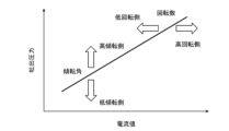
- FIG. 3 is a diagram for explaining a map stored in a control device. It is a sectional view of a hydraulic rotary machine of a modification.
- FIG. 1 shows a hydraulic rotating machine 1 according to an embodiment.
- This hydraulic rotating machine 1 includes a casing 2 and a rotating shaft 11 extending from the inside of the casing 2 to the outside. Furthermore, the hydraulic rotary machine 1 includes a valve plate 3, a cylinder block 4 and a swash plate 5 housed within a casing 2.
- the axial direction of the rotating shaft 11 will be referred to as the front-rear direction (one end located outside the casing 2 is the front, the other end is the rear), and the two directions orthogonal to the axial direction of the rotating shaft 11 are referred to as the up and down directions.
- direction the upper side in FIG. 1 is upward and the lower side is downward
- left-right direction the upper side in FIG. 1 is upward and the lower side is downward
- the casing 2 includes a container-shaped casing body 22 that opens rearward, and a valve cover 21 that closes the opening of the casing body 22.
- the casing body 22 includes a front wall 23 penetrated by the rotating shaft 11, a bottom wall 24 surrounding an internal space, a ceiling wall 25, and a pair of side walls. Bearings 12 and 13 that rotatably support the rotating shaft 11 are held in the front wall 23 of the casing body 22 and the valve cover 21, respectively.
- the valve plate 3 is attached to the front surface of the valve cover 21.
- the valve plate 3 is provided with a first port 31 and a second port 32 which are arcuate and have opposite directions.
- the first port 31 is shown at the lower top dead center (the position where the piston 61, which will be described later, is the most backward)
- the second port 32 is shown at the upper bottom dead center (the position where the piston 61 is the most advanced).
- the actual positions of the first port 31 and the second port 32 are on both sides of the rotating shaft 11 in the left-right direction (direction perpendicular to the direction of separation between the top dead center and the bottom dead center).
- the hydraulic rotating machine 1 is a hydraulic pump that rotates in one direction. Therefore, the first port 31 is a suction port, and the second port 32 is a discharge port. That is, in the rotational direction of the rotating shaft 11, the first port 31, which is the suction port, is located downstream of the top dead center and upstream of the bottom dead center, and the second port 32, which is the discharge port, is located downstream of the top dead center and upstream of the bottom dead center. It is located downstream of the bottom dead center and upstream of the top dead center.
- the valve cover 21 is provided with a first passage 2a communicating with the first port 31 and a second passage 2b communicating with the second port 32.
- the first flow path 2a and the second flow path 2b open on the outer peripheral surface or rear surface of the valve cover 21, and these openings form external connection ports.
- the hydraulic rotary machine 1 is a hydraulic pump that rotates in one direction, so the first flow path 2a is the suction path and the second flow path 2b is the discharge path. That is, the pressure in the second flow path 2b is higher than the pressure in the first flow path 2a.
- the cylinder block 4 is fixed to the rotating shaft 11, and slides on the valve plate 3 by rotating together with the rotating shaft 11.
- the cylinder block 4 is provided with a plurality of cylinder bores 41 that open forward, around the rotating shaft 11.
- a plurality of pistons 61 are inserted into these cylinder bores 41, respectively. Thereby, the piston 61 is slidably held in the cylinder block 4.
- the cylinder block 4 is provided with cylinder ports 42 extending from each cylinder bore 41 to the valve plate 3. Some of these cylinder ports 42 communicate with the first port 31 and some communicate with the second port 32. For example, when the number of cylinder bores 41 and cylinder ports 42 is nine, four or five cylinder ports 42 communicate with the first port 31 or the second port 32 depending on the rotational position of the cylinder block 4.
- a plurality of shoes 62 are each attached to the head of the piston 61.
- the shoe 62 slides on the swash plate 5 via an annular shoe plate 63 attached to the swash plate 5.
- the shoe plate 63 may be omitted and the shoe 62 may slide directly on the swash plate 5.
- the shoe 62 is held down by a holding plate 64 so as to maintain contact with the shoe plate 63.
- the swash plate 5 is supported by a support base 14 provided on the front wall 23 of the casing body 22 so as to be swingable around a swing axis extending in the left-right direction.
- the angle of the swash plate 5 is changed by a servo piston 7, which is slidably held on a ceiling wall 25 of the casing body 22.
- the swash plate 5 includes a main body portion 50 that is penetrated by the rotating shaft 11, and an operating portion 51 that projects upward from the main body portion 50.
- a tip 71 of the servo piston 7 is connected to the operating portion 51 via a pin 52.
- the servo piston 7 does not necessarily need to be connected to the operating portion 51 of the swash plate 5.
- the servo piston 7 abuts the operating portion 51 of the swash plate 5 from the rear, and the operating portion 51 is biased backward by a spring disposed between the operating portion 51 and the front wall 23 of the casing body 22. It's okay.
- a holding hole 26 into which the servo piston 7 is inserted is provided in the ceiling wall 25 of the casing body 22.
- the holding hole 26 includes a first guide part 27 that forms an opening to the internal space of the casing 2 and a second guide part 28 that is located on the opposite side of the swash plate 5 with respect to the first guide part 27. include.
- the diameter of the second guide part 28 is smaller than the diameter of the first guide part 27.
- the servo piston 7 is slidably held by a first sliding part 72 which is adjacent to the above-mentioned tip part 71 and which is slidably held by the first guide part 27 and by a second guide part 28.
- a second sliding portion 73 is included. That is, the diameter of the first sliding part 72 is approximately equal to the diameter of the first guide part 27, and the diameter of the second sliding part 73 is approximately equal to the diameter of the second guide part 28.
- auxiliary pressure is applied between the annular end surface of the first sliding part 72 on the second sliding part 73 side and the stepped part between the first guide part 27 and the second guide part 28 in the holding hole 26.
- a chamber 91 is formed. This auxiliary pressure chamber 91 is for pressing the servo piston 7 toward the swash plate 5.
- the casing body 22 and the valve cover 21 are provided with an introduction path 2c that branches from the second flow path 2b and reaches the auxiliary pressure chamber 91.
- the introduction path 2c introduces the working fluid from the discharge path to the auxiliary pressure chamber 91.
- An electromagnetic proportional valve 92 that sets the pressure in the auxiliary pressure chamber 91 is provided in the introduction path 2c.
- the electromagnetic proportional valve 92 functions as a pressure reducing valve that reduces the discharge pressure of the hydraulic pump to a set pressure.
- the electromagnetic proportional valve 92 is an inverse proportional type in which the command current and the secondary pressure have a negative correlation, but the electromagnetic proportional valve 92 is a direct proportional type in which the command current and the secondary pressure are in a positive correlation. Good too.
- An electric actuator 8 that drives the servo piston 7 is attached to the ceiling wall 25 of the casing body 22.
- the electric actuator 8 includes a threaded shaft 84 extending along the axial direction of the servo piston 7 , a nut 83 that threads into the threaded shaft 84 , and an electric motor 86 that rotates the threaded shaft 84 .
- the electric actuator 8 includes a hollow rod 82 connected to the servo piston 7 and having a nut 83 fixed thereto, and a cylindrical housing 85 that holds the rod 82 slidably in the axial direction of the servo piston 7. .
- the housing 85 is fixed to the ceiling wall 25 of the casing body 22, and an electric motor 86 is attached to the housing 85.
- the rod 82 is connected to the servo piston 7 via a universal joint. Specifically, a slot is provided at the front end of the rod 82, and the ball 81 is held in this slot.
- the second sliding portion 73 of the servo piston 7 is provided with a plate-shaped projection 74 that is inserted into the slot, and this projection 74 is provided with a hole into which the ball 81 fits.
- the second sliding portion 73 of the servo piston 7 may be provided with a slot for holding the ball 81, and the front end of the rod 82 may be provided with a protrusion 74 that is inserted into the slot.
- the rod 82 may be connected to the servo piston 7 by a joint other than a universal joint (for example, a ball joint, a spherical joint, etc.).
- the electric motor 86 is controlled by the control device 15.
- the control device 15 is electrically connected to a rotation angle sensor 16 that detects the rotation angle of the electric motor 86.
- the rotation angle sensor 16 is a resolver, a rotary encoder, or the like.
- Information for determining the tilt angle, which is the angle of the swash plate 5, is input to the control device 15.
- the control device 15 adjusts the current supplied to the electric motor 86 so that the rotation angle of the electric motor 86 detected by the rotation angle sensor 16 is maintained at a predetermined value according to the input information.
- the hydraulic rotary machine 1 which is a hydraulic pump
- the amount of operation of the operating device is controlled.
- the control device 15 increases the tilt angle of the hydraulic pump as the amount of operation of the operating device increases.
- the functionality of the elements disclosed herein may include general purpose processors, special purpose processors, integrated circuits, ASICs (Application Specific Integrated Circuits), conventional circuits configured or programmed to perform the disclosed functions; and/or a combination thereof.
- Processors are considered processing circuits or circuits because they include transistors and other circuits.
- a circuit, unit, or means is hardware that performs the recited functions or is hardware that is programmed to perform the recited functions.
- the hardware may be the hardware disclosed herein or other known hardware that is programmed or configured to perform the recited functions. If the hardware is a processor, which is considered a type of circuit, the circuit, means or unit is a combination of hardware and software, the software being used in the configuration of the hardware and/or the processor.
- control device 15 calculates the rotation speed of the rotating shaft 11 based on the adjusted current waveform, and determines the discharge pressure of the hydraulic pump using the map shown in FIG. .
- the control device 15 calculates the number of vibrations K of the current in a predetermined time T [s] from the adjusted current waveform, Using this number of vibrations K and the number Z of pistons 61, the number of rotations N of the rotating shaft 11 is calculated by the following formula.
- the predetermined time T is 0.1 to 0.5 seconds.
- N K/2 ⁇ 1/Z ⁇ 1/T ⁇ 60
- the hydraulic rotary machine 1 is a hydraulic pump, so a moment that presses the servo piston 7 acts on the swash plate 5 due to the high pressure in the cylinder block 4.
- this moment is caused by the relative positional relationship between the cylinder block 4 and the valve plate 3 (in this embodiment, the switching of communication between the cylinder port 42 of the cylinder block 4 and the second port 32, which is the discharge port of the valve plate 3).
- the current that is adjusted to maintain the rotation angle of the electric motor 86 at a predetermined value oscillates, and the frequency of the oscillation has a correlation with the rotation speed of the rotating shaft 11. Therefore, by calculating the rotation speed of the rotation shaft 11 based on the adjusted current waveform, the rotation speed of the rotation shaft 11 can be detected without using a rotation speed meter.
- relatively high pressure hydraulic fluid is introduced into the auxiliary pressure chamber 91, and the servo piston 7 is pressed toward the swash plate 5 by the pressure. Therefore, the electric actuator 8 can move the servo piston 7 forward with a small propulsive force.
- the control device 15 includes the discharge pressure of the hydraulic pump, the tilt angle that is the angle of the swash plate 5, and the rotation speed of the rotating shaft 11, as shown in FIG.
- a map defining the relationship with the current value of the electric motor 86 is stored in advance.
- the relationship between the discharge pressure of the hydraulic pump and each parameter is that as the discharge pressure increases, the current value of the electric motor 86 increases, and as the tilting angle increases, the current value of the electric motor 86 decreases with respect to the discharge pressure. As the rotational speed of the rotating shaft 11 increases, the current value of the electric motor 86 increases relative to the discharge pressure.
- the map shown in FIG. 3 can be obtained by performing a performance confirmation test on the hydraulic rotating machine 1, which is a hydraulic pump, in advance.
- the relationship between the current value of the electric motor 86 and the discharge pressure of the hydraulic pump is represented by a straight line in FIG. 3, the relationship may be represented by a curve.
- the control device 15 calculates the tilt angle converted from the rotation angle of the electric motor 86 detected by the rotation angle sensor 16, the calculated rotation speed, and the average value of the adjusted current. Determine the discharge pressure of the corresponding hydraulic pump.
- the discharge pressure of the hydraulic pump has a correlation with the tilt angle that is the angle of the swash plate 5, the rotation speed of the rotating shaft 11, and the current value of the electric motor 86. Therefore, by using a map that defines these relationships, the discharge pressure of the hydraulic pump can be detected without using a pressure gauge.
- the hydraulic rotating machine 1 may be a hydraulic pump that rotates in both directions.
- the introduction path 2c is connected to both the first flow path 2a and the second flow path 2b via the high pressure selection valve 93, as in the modified hydraulic rotary machine 1A shown in FIG. Even in this configuration, the introduction path 2c introduces the working fluid into the auxiliary pressure chamber 91 from the discharge path, which is the higher pressure one of the first flow path 2a and the second flow path 2b.
- the hydraulic rotating machine 1 may be a hydraulic motor that rotates in both directions. In this case, depending on the direction of rotation, one of the first flow path 2a and the second flow path 2b becomes an inflow path and the other becomes an outflow path, and one of the first port 31 and the second port 32 becomes an inflow port and the other becomes the outflow port.
- the hydraulic rotary machine 1 When the hydraulic rotary machine 1 is a hydraulic motor, a moment acts on the swash plate 5 due to the high pressure in the cylinder block 4 to pull out the servo piston 7. In this case as well, as in the embodiment described above, the moment is slightly reduced by the relative positional relationship between the cylinder block 4 and the valve plate 3 (switching of communication between the cylinder port 42 of the cylinder block 4 and the inflow port of the valve plate 3). Change. Therefore, the current that is adjusted to maintain the rotation angle of the electric motor 86 at a predetermined value oscillates, and the frequency of the oscillation has a correlation with the rotation speed of the rotating shaft 11. Therefore, by calculating the rotation speed of the rotation shaft 11 based on the adjusted current waveform, the rotation speed of the rotation shaft 11 can be detected without using a rotation speed meter.
- the rotation speed of the prime mover that drives the hydraulic pump is input to the control device 15 as the rotation speed of the rotating shaft 11, and the control device 15 uses the rotation speed instead of the calculated rotation speed.
- the input rotation speed may be used to determine the discharge pressure of the hydraulic pump.
- the present disclosure includes, from one side, a rotating shaft, a cylinder block that is fixed to the rotating shaft and slidably holds a plurality of pistons, and a cylinder block that slides with a shoe attached to the heads of the plurality of pistons.
- an electric actuator that drives an electric actuator that includes a screw shaft extending along the axial direction of the servo piston, a nut that screws into the screw shaft, and an electric motor that rotates the screw shaft; and a rotation of the electric motor.
- a rotation angle sensor that detects an angle and a control device that controls the electric motor, the control device configured to maintain a rotation angle of the electric motor detected by the rotation angle sensor at a predetermined value.
- the present invention provides a hydraulic rotating machine that adjusts the current supplied to the electric motor and calculates the rotation speed of the rotating shaft based on the waveform of the adjusted current.
- the hydraulic rotating machine is a hydraulic pump
- the high pressure inside the cylinder block will exert a moment that presses the servo piston against the swash plate
- the hydraulic rotating machine is a hydraulic motor
- the moment will act on the swash plate due to the high pressure inside the cylinder block.
- the high pressure exerts a moment on the swash plate that pulls out the servo piston. This moment also depends on the relative positional relationship between the cylinder block and the valve plate (if the hydraulic rotary machine is a hydraulic pump, switching of communication between the cylinder port provided in the cylinder block and the discharge port of the valve plate). Changes minutely.
- the current that is adjusted to maintain the rotation angle of the electric motor at a predetermined value oscillates, and the frequency of the oscillation has a correlation with the rotation speed of the rotating shaft. Therefore, by calculating the rotation speed of the rotation shaft based on the adjusted current waveform, the rotation speed of the rotation shaft can be detected without using a rotation speed meter.
- control device may calculate the number of oscillations of the current in a predetermined time from the adjusted current waveform, and use this number of oscillations to calculate the number of rotations of the rotating shaft.
- the hydraulic rotary machine is a hydraulic pump, and the hydraulic rotary machine includes a first port and a second port that are arcuate in opposite directions and that are housed in the casing and slide on the cylinder block.
- the casing further includes a valve plate, and the casing includes an auxiliary pressure chamber for pressing the servo piston toward the swash plate, a first passage communicating with the first port, and a second passage communicating with the second port. It may include two flow paths and an introduction path for introducing the working fluid into the auxiliary pressure chamber from the discharge path which is the higher pressure one of the first flow path and the second flow path. According to this configuration, relatively high pressure hydraulic fluid is introduced into the auxiliary pressure chamber, and the servo piston is pressed toward the swash plate by the pressure. Therefore, the electric actuator can move the servo piston forward with a small propulsive force.
- the hydraulic rotary machine is a hydraulic pump
- the control device includes the discharge pressure of the hydraulic pump, the tilt angle that is the angle of the swash plate, the rotation speed of the rotating shaft, and the electric motor.
- a map defining the relationship between the current value and the current value is stored in advance, and the control device uses the map to determine the tilt angle converted from the rotation angle of the electric motor detected by the rotation angle sensor;
- a discharge pressure of the hydraulic pump corresponding to the calculated rotation speed and the adjusted average value of the current may be determined.
- the discharge pressure of the hydraulic pump has a correlation with the tilt angle that is the angle of the swash plate, the rotation speed of the rotating shaft, and the current value of the electric motor. Therefore, by using a map that defines these relationships, the discharge pressure of the hydraulic pump can be detected without using a pressure gauge.
- a hydraulic pump including a rotating shaft, a cylinder block fixed to the rotating shaft and slidably holding a plurality of pistons, and heads of the plurality of pistons.
- a swash plate that slides on a shoe attached to the swash plate;
- a servo piston that changes the angle of the swash plate;
- a casing that accommodates the cylinder block and the swash plate and slidably holds the servo piston;
- An electric actuator that is attached to the casing and drives the servo piston, and includes a screw shaft that extends along the axial direction of the servo piston, a nut that threadably engages with the screw shaft, and an electric motor that rotates the screw shaft.
- the control device includes an electric actuator, a rotation angle sensor that detects a rotation angle of the electric motor, and a control device that controls the electric motor, and the control device detects the rotation angle of the electric motor detected by the rotation angle sensor.
- the control device controls the discharge pressure of the hydraulic pump, the tilt angle that is the angle of the swash plate, and the rotation.
- a map defining the relationship between the rotation speed of the shaft and the current value of the electric motor is stored in advance, and the control device uses the map to determine the relationship between the rotation speed of the shaft and the current value of the electric motor detected by the rotation angle sensor.
- the present invention provides a hydraulic pump that determines a discharge pressure of the hydraulic pump corresponding to a tilt angle converted into a rotation angle, a rotation speed of the rotating shaft, and an average value of the adjusted current.
- the discharge pressure of the hydraulic pump has a correlation with the tilt angle that is the angle of the swash plate, the rotation speed of the rotating shaft, and the current value of the electric motor. Therefore, by using a map that defines these relationships, the discharge pressure of the hydraulic pump can be detected without using a pressure gauge.
Landscapes
- Engineering & Computer Science (AREA)
- Mechanical Engineering (AREA)
- General Engineering & Computer Science (AREA)
- Reciprocating Pumps (AREA)
Abstract
一実施形態に係る液圧回転機械(1)は、回転軸(11)と、シリンダブロック(4)および斜板(5)を収容するケーシング(2)を含む。また、液圧回転機械(1)は、斜板(5)の角度を変更するサーボピストン(7)と、サーボピストン(7)を駆動する電動アクチュエータ(8)を含む。電動アクチュエータ(8)は、ねじ軸(84)、ナット(83)および電動モータ(86)を含む。電動モータ(86)の回転角度は回転角度センサ(16)により検出され、電動モータ(86)は制御装置(15)によって制御される。制御装置(15)は、回転角度センサ(16)で検出される電動モータ(86)の回転角度が所定値に保たれるように電動モータ(86)へ送給する電流を調整し、調整された電流の波形に基づいて回転軸(11)の回転数を算出する。
Description
本開示は、液圧回転機械および液圧ポンプに関する。
従来から、斜板式のアキシャルピストンポンプである液圧回転機械(液圧ポンプまたは液圧モータ)が知られている。このような液圧回転機械では、ケーシング内に、シリンダブロックおよび斜板が収容される(例えば、特許文献1参照)。シリンダブロックは、ケーシングの内部から外部まで延びる回転軸に固定される。
シリンダブロックには複数のピストンが摺動可能に保持され、それらのピストンの頭部に取り付けられたシューが斜板と摺動する。斜板の角度は、サーボピストンによって変更される。特許文献2には、サーボピストンを電動アクチュエータで駆動する液圧回転機械が開示されている。特許文献2には、電動アクチュエータの具体例として、ボールねじ駆動機構が記載されている。
サーボピストンの駆動方式としては、サーボピストンに作用する液圧を変更する方式もある。しかし、この場合には、サーボピストンの駆動が作動液の温度変化の影響を受けるおそれがある。これに対し、特許文献2の具体例のように、ボールねじ駆動機構(すなわち、ねじ軸、ナットおよび電動モータを含む電動アクチュエータ)を用いてサーボピストンを駆動すれば、そのような問題は生じない。
ところで、液圧回転機械においては、回転数計を用いることなく回転軸の回転数を検出したいという要望がある。また、液圧回転機械が液圧ポンプである場合は、圧力計を用いることなく液圧ポンプの吐出圧力を検出したいという要望がある。
そこで、本開示は、回転数計を用いることなく回転軸の回転数を検出することができる液圧回転機械を提供することを目的とする。また、本開示は、圧力計を用いることなく吐出圧力を検出することができる液圧ポンプを提供することも目的とする。
本開示は、一つの側面から、回転軸と、前記回転軸に固定され、複数のピストンを摺動可能に保持するシリンダブロックと、前記複数のピストンの頭部に取り付けられたシューと摺動する斜板と、前記斜板の角度を変更するサーボピストンと、前記シリンダブロックおよび前記斜板を収容するとともに、前記サーボピストンを摺動可能に保持するケーシングと、前記ケーシングに取り付けられて前記サーボピストンを駆動する電動アクチュエータであって、前記サーボピストンの軸方向に沿って延びるねじ軸、前記ねじ軸と螺合するナットおよび前記ねじ軸を回転させる電動モータを含む電動アクチュエータと、前記電動モータの回転角度を検出する回転角度センサと、前記電動モータを制御する制御装置と、を備え、前記制御装置は、前記回転角度センサで検出される前記電動モータの回転角度が所定値に保たれるように前記電動モータへ送給する電流を調整し、調整された電流の波形に基づいて前記回転軸の回転数を算出する、液圧回転機械を提供する。
また、本開示は、別の側面から、液圧ポンプであって、回転軸と、前記回転軸に固定され、複数のピストンを摺動可能に保持するシリンダブロックと、前記複数のピストンの頭部に取り付けられたシューと摺動する斜板と、前記斜板の角度を変更するサーボピストンと、前記シリンダブロックおよび前記斜板を収容するとともに、前記サーボピストンを摺動可能に保持するケーシングと、前記ケーシングに取り付けられて前記サーボピストンを駆動する電動アクチュエータであって、前記サーボピストンの軸方向に沿って延びるねじ軸、前記ねじ軸と螺合するナットおよび前記ねじ軸を回転させる電動モータを含む電動アクチュエータと、前記電動モータの回転角度を検出する回転角度センサと、前記電動モータを制御する制御装置と、を備え、前記制御装置は、前記回転角度センサで検出される前記電動モータの回転角度が所定値に保たれるように前記電動モータへ送給する電流を調整し、前記制御装置には、前記液圧ポンプの吐出圧力と、前記斜板の角度である傾転角と、前記回転軸の回転数と、前記電動モータの電流値との関係を定めたマップが予め格納されており、前記制御装置は、前記マップを使用して、前記回転角度センサで検出される前記電動モータの回転角度を換算した傾転角、前記回転軸の回転数、及び調整された電流の平均値に対応する前記液圧ポンプの吐出圧力を決定する、液圧ポンプを提供する。
本開示によれば、回転数計を用いることなく回転軸の回転数を検出することができる液圧回転機械が提供されるとともに、圧力計を用いることなく吐出圧力を検出することができる液圧ポンプが提供される。
図1に、一実施形態に係る液圧回転機械1を示す。この液圧回転機械1は、ケーシング2と、ケーシング2の内部から外部まで延びる回転軸11を含む。さらに、液圧回転機械1は、ケーシング2内に収容されたバルブプレート3、シリンダブロック4および斜板5を含む。
以下、説明の便宜上、回転軸11の軸方向を前後方向(ケーシング2の外部に位置する一端側を前方、他端側を後方)というとともに、回転軸11の軸方向と直交する二方向を上下方向(図1の上側を上方、下側を下方)および左右方向という。
ケーシング2は、後ろ向きに開口する容器状のケーシング本体22と、ケーシング本体22の開口を閉塞するバルブカバー21を含む。ケーシング本体22は、回転軸11に貫通される前壁23と、内部空間を取り囲む底壁24、天井壁25および一対の側壁を含む。ケーシング本体22の前壁23およびバルブカバー21には、回転軸11を回転可能に支持する軸受12,13がそれぞれ保持されている。
バルブプレート3はバルブカバー21の前面に取り付けられている。バルブプレート3には、互いに反対向きの円弧状の第1ポート31および第2ポート32が設けられている。図1では、第1ポート31を下側の上死点(後述するピストン61が最も後退する位置)、第2ポート32を上側の下死点(ピストン61が最も前進する位置)に描いているが、実際の第1ポート31と第2ポート32の位置は、左右方向(前記上死点と前記下死点との離間方向と直交する方向)において回転軸11の両側である。
本実施形態では、液圧回転機械1が一方向に回転する液圧ポンプである。このため、第1ポート31が吸入ポート、第2ポート32が吐出ポートである。すなわち、回転軸11の回転方向において、吸入ポートである第1ポート31は前記上死点の下流側であって前記下死点の上流側に位置し、吐出ポートである第2ポート32は前記下死点の下流側であって前記上死点の上流側に位置する。
バルブカバー21には、第1ポート31と連通する第1流路2aと、第2ポート32と連通する第2流路2bが設けられている。第1流路2aおよび第2流路2bはバルブカバー21の外周面または後面に開口し、これらの開口が外部接続ポートを形成する。上述したように液圧回転機械1は一方向に回転する液圧ポンプであるため、第1流路2aが吸入路であり、第2流路2bが吐出路である。すなわち、第2流路2bの圧力は、第1流路2aの圧力よりも高い。
シリンダブロック4は、回転軸11に固定されており、回転軸11と共に回転することでバルブプレート3と摺動する。シリンダブロック4には、回転軸11の周囲に、前向きに開口する複数のシリンダボア41が設けられている。これらのシリンダボア41には、複数のピストン61がそれぞれ挿入されている。これにより、ピストン61がシリンダブロック4に摺動可能に保持される。
また、シリンダブロック4には、各シリンダボア41からバルブプレート3に至るシリンダポート42が設けられている。これらのシリンダポート42のうちのいくつかが第1ポート31と連通し、別のいくつかが第2ポート32と連通する。例えば、シリンダボア41およびシリンダポート42の数が9つの場合、シリンダブロック4の回転位置によって4つまたは5つのシリンダポート42が第1ポート31または第2ポート32と連通する。
ピストン61の頭部には、複数のシュー62がそれぞれ取り付けられている。本実施形態では、シュー62が、斜板5に取り付けられた環状のシュープレート63を介して斜板5と摺動する。ただし、シュープレート63が省略されて、シュー62が斜板5と直接的に摺動してもよい。シュー62は、シュープレート63に接触した状態が維持されるように、押え板64によって押えられている。
斜板5は、ケーシング本体22の前壁23に設けられた支持台14によって、左右方向に延びる揺動軸回りに揺動可能に支持されている。斜板5の角度はサーボピストン7によって変更され、サーボピストン7は、ケーシング本体22の天井壁25に摺動可能に保持されている。
より詳しくは、斜板5は、回転軸11に貫通される本体部50と、本体部50から上向きに突出する操作部51を含む。本実施形態では、操作部51に、サーボピストン7の先端部71がピン52を介して連結されている。
ただし、サーボピストン7は必ずしも斜板5の操作部51に連結される必要はない。例えば、サーボピストン7が斜板5の操作部51に後方から当接し、操作部51が、当該操作部51とケーシング本体22の前壁23との間に配置されたスプリングによって後ろ向きに付勢されてもよい。
ケーシング本体22の天井壁25には、サーボピストン7が挿入される保持穴26が設けられている。本実施形態では、保持穴26が、ケーシング2の内部空間に対する開口を形成する第1ガイド部27と、第1ガイド部27に対して斜板5と反対側に位置する第2ガイド部28を含む。第2ガイド部28の直径は、第1ガイド部27の直径よりも小さい。
一方、サーボピストン7は、上述した先端部71に隣接する、第1ガイド部27に摺動可能に保持される第1摺動部72と、第2ガイド部28に摺動可能に保持される第2摺動部73を含む。つまり、第1摺動部72の直径は第1ガイド部27の直径とほぼ等しく、第2摺動部73の直径は第2ガイド部28の直径とほぼ等しい。
そして、第1摺動部72の第2摺動部73側の環状の端面と、保持穴26における第1ガイド部27と第2ガイド部28との間の段差部との間に、補助圧力室91が形成されている。この補助圧力室91は、サーボピストン7を斜板5に向かって押圧するためのものである。
ケーシング本体22およびバルブカバー21には、第2流路2bから分岐して補助圧力室91に至る導入路2cが設けられている。本実施形態では、上述したように第2流路2bが吐出路であるので、導入路2cは、吐出路から補助圧力室91へ作動液を導入する。
導入路2cには、補助圧力室91の圧力を設定する電磁比例弁92が設けられている。本実施形態では、電磁比例弁92が液圧ポンプの吐出圧力を設定圧まで減圧する減圧弁として機能する。図例では、電磁比例弁92が指令電流と二次圧が負の相関を示す逆比例型であるが、電磁比例弁92は指令電流と二次圧が正の相関を示す正比例型であってもよい。
ケーシング本体22の天井壁25には、サーボピストン7を駆動する電動アクチュエータ8が取り付けられている。電動アクチュエータ8は、サーボピストン7の軸方向に沿って延びるねじ軸84と、ねじ軸84と螺合するナット83と、ねじ軸84を回転させる電動モータ86を含む。
さらに、電動アクチュエータ8は、サーボピストン7と連結されるとともにナット83が固定された中空のロッド82と、ロッド82をサーボピストン7の軸方向に摺動可能に保持する筒状のハウジング85を含む。ハウジング85はケーシング本体22の天井壁25に固定され、このハウジング85に電動モータ86が取り付けられている。
本実施形態では、ロッド82がユニバーサルジョイントを介してサーボピストン7と連結されている。具体的には、ロッド82の前端にスロットが設けられており、このスロットにボール81が保持されている。一方、サーボピストン7の第2摺動部73には、そのスロット内に挿入される板状の突起74が設けられており、この突起74にボール81と嵌合する穴が設けられている。
ただし、本実施形態とは逆に、サーボピストン7の第2摺動部73にボール81を保持するスロットが設けられ、ロッド82の前端にスロット内に挿入される突起74が設けられてもよい。あるいは、ロッド82は、ユニバーサルジョイント以外のジョイント(例えば、ボールジョイントや球面ジョイントなど)によりサーボピストン7と連結されてもよい。
電動モータ86は、制御装置15によって制御される。制御装置15は、電動モータ86の回転角度を検出する回転角度センサ16と電気的に接続されている。例えば、回転角度センサ16は、レゾルバやロータリエンコーダなどである。制御装置15には、斜板5の角度である傾転角を決定するための情報が入力される。制御装置15は、回転角度センサ16で検出される電動モータ86の回転角度が、入力される情報に応じた所定値に保たれるように、電動モータ86へ送給する電流を調整する。
例えば、液圧ポンプである液圧回転機械1が制御弁を介して液圧アクチュエータへ作動液を供給し、その制御弁を作動させるための操作装置が設けられる場合、操作装置の操作量が制御装置15に入力され、制御装置15は操作装置の操作量が大きくなるほど液圧ポンプの傾倒角を大きくする。
制御装置15に関し、本明細書で開示する要素の機能は、開示された機能を実行するよう構成またはプログラムされた汎用プロセッサ、専用プロセッサ、集積回路、ASIC(Application Specific Integrated Circuits)、従来の回路、および/または、それらの組み合わせ、を含む回路または処理回路を使用して実行できる。プロセッサは、トランジスタやその他の回路を含むため、処理回路または回路と見なされる。本開示において、回路、ユニット、または手段は、列挙された機能を実行するハードウエアであるか、または、列挙された機能を実行するようにプログラムされたハードウエアである。ハードウエアは、本明細書に開示されているハードウエアであってもよいし、あるいは、列挙された機能を実行するようにプログラムまたは構成されているその他の既知のハードウエアであってもよい。ハードウエアが回路の一種と考えられるプロセッサである場合、回路、手段、またはユニットはハードウエアとソフトウエアの組み合わせであり、ソフトウエアはハードウエアおよび/またはプロセッサの構成に使用される。
さらに、本実施形態では、制御装置15が、調整された電流の波形に基づいて回転軸11の回転数を算出するとともに、図3に示すマップを使用して液圧ポンプの吐出圧力を決定する。
回転軸11の回転数N[rpm]の算出に関しては、図2に示すように、制御装置15は、調整された電流の波形から、所定時間T[s]における電流の振動回数Kを求め、この振動回数Kおよびピストン61の本数Zを使用して以下の式により回転軸11の回転数Nを算出する。例えば、所定時間Tは0.1~0.5sである。
N=K/2×1/Z×1/T×60
N=K/2×1/Z×1/T×60
本実施形態では液圧回転機械1が液圧ポンプであるので、斜板5には、シリンダブロック4内の高圧によってサーボピストン7を押圧するようなモーメントが作用する。また、このモーメントは、シリンダブロック4とバルブプレート3の相対位置関係(本実施形態では、シリンダブロック4のシリンダポート42と、バルブプレート3の吐出ポートである第2ポート32の連通の切り換わり)によって微小に変化する。このため、電動モータ86の回転角度を所定値に保つように調整される電流は振動し、その振動数は回転軸11の回転数と相関関係がある。従って、調整された電流の波形に基づいて回転軸11の回転数を算出することで、回転数計を用いることなく回転軸11の回転数を検出することができる。
また、本実施形態では、補助圧力室91に比較的に圧力の高い作動液が導入され、その圧力によってサーボピストン7が斜板5に向かって押圧される。従って、電動アクチュエータ8が小さな推進力でサーボピストン7を前進させることができる。
液圧ポンプの吐出圧力の決定に関しては、制御装置15には、図3に示す、液圧ポンプの吐出圧力と、斜板5の角度である傾転角と、回転軸11の回転数と、電動モータ86の電流値との関係を定めたマップが予め格納されている。液圧ポンプの吐出圧力と各パラメータとの関係としては、吐出圧力が高くなると電動モータ86の電流値が高くなり、傾転角が大きくなると吐出圧力に対して電動モータ86の電流値が小さくなり、回転軸11の回転数が高くなると吐出圧力に対して電動モータ86の電流値が大きくなる。
図3に示すマップは、液圧ポンプである液圧回転機械1に対して事前に性能確認試験を行うことで得ることができる。なお、図3では、電動モータ86の電流値と液圧ポンプの吐出圧力との関係が直線で表されているが、その関係は曲線で表されてもよい。
制御装置15は、図3に示すマップを使用して、回転角度センサ16で検出される電動モータ86の回転角度を換算した傾転角、算出した回転数、及び調整された電流の平均値に対応する液圧ポンプの吐出圧力を決定する。
液圧ポンプの吐出圧力は、斜板5の角度である傾転角、回転軸11の回転数、および電動モータ86の電流値と相関関係がある。従って、それらの関係を定めたマップを使用することで、圧力計を用いることなく液圧ポンプの吐出圧力を検出することができる。
(変形例)
本開示は上述した実施形態に限定されるものではなく、本開示の要旨を逸脱しない範囲で種々の変形が可能である。
本開示は上述した実施形態に限定されるものではなく、本開示の要旨を逸脱しない範囲で種々の変形が可能である。
例えば、液圧回転機械1は両方向に回転する液圧ポンプであってもよい。この場合、図4に示す変形例の液圧回転機械1Aのように、導入路2cは、高圧選択弁93を介して第1流路2aと第2流路2bの双方と接続される。この構成でも、導入路2cは、第1流路2aと第2流路2bのうちの圧力の高い方である吐出路から補助圧力室91へ作動液を導入する。
あるいは、液圧回転機械1は両方向に回転する液圧モータであってもよい。この場合、回転方向によって、第1流路2aと第2流路2bのどちらか一方が流入路、他方が流出路となり、第1ポート31と第2ポート32のどちらか一方が流入ポート、他方が流出ポートとなる。
液圧回転機械1が液圧モータである場合、シリンダブロック4内の高圧によって斜板5にサーボピストン7を引き抜くようなモーメントが作用する。この場合でも前記実施形態と同様に、そのモーメントが、シリンダブロック4とバルブプレート3の相対位置関係(シリンダブロック4のシリンダポート42と、バルブプレート3の流入ポートの連通の切り換わり)によって微小に変化する。このため、電動モータ86の回転角度を所定値に保つように調整される電流は振動し、その振動数は回転軸11の回転数と相関関係がある。従って、調整された電流の波形に基づいて回転軸11の回転数を算出することで、回転数計を用いることなく回転軸11の回転数を検出することができる。
また、液圧ポンプの吐出圧力の決定に関しては、液圧ポンプを駆動する原動機の回転数が回転軸11の回転数として制御装置15に入力され、制御装置15が、算出した回転数の代わりに入力された回転数を使用して液圧ポンプの吐出圧力を決定してもよい。
(まとめ)
本開示は、一つの側面から、回転軸と、前記回転軸に固定され、複数のピストンを摺動可能に保持するシリンダブロックと、前記複数のピストンの頭部に取り付けられたシューと摺動する斜板と、前記斜板の角度を変更するサーボピストンと、前記シリンダブロックおよび前記斜板を収容するとともに、前記サーボピストンを摺動可能に保持するケーシングと、前記ケーシングに取り付けられて前記サーボピストンを駆動する電動アクチュエータであって、前記サーボピストンの軸方向に沿って延びるねじ軸、前記ねじ軸と螺合するナットおよび前記ねじ軸を回転させる電動モータを含む電動アクチュエータと、前記電動モータの回転角度を検出する回転角度センサと、前記電動モータを制御する制御装置と、を備え、前記制御装置は、前記回転角度センサで検出される前記電動モータの回転角度が所定値に保たれるように前記電動モータへ送給する電流を調整し、調整された電流の波形に基づいて前記回転軸の回転数を算出する、液圧回転機械を提供する。
本開示は、一つの側面から、回転軸と、前記回転軸に固定され、複数のピストンを摺動可能に保持するシリンダブロックと、前記複数のピストンの頭部に取り付けられたシューと摺動する斜板と、前記斜板の角度を変更するサーボピストンと、前記シリンダブロックおよび前記斜板を収容するとともに、前記サーボピストンを摺動可能に保持するケーシングと、前記ケーシングに取り付けられて前記サーボピストンを駆動する電動アクチュエータであって、前記サーボピストンの軸方向に沿って延びるねじ軸、前記ねじ軸と螺合するナットおよび前記ねじ軸を回転させる電動モータを含む電動アクチュエータと、前記電動モータの回転角度を検出する回転角度センサと、前記電動モータを制御する制御装置と、を備え、前記制御装置は、前記回転角度センサで検出される前記電動モータの回転角度が所定値に保たれるように前記電動モータへ送給する電流を調整し、調整された電流の波形に基づいて前記回転軸の回転数を算出する、液圧回転機械を提供する。
液圧回転機械が液圧ポンプである場合は、シリンダブロック内の高圧によって斜板にサーボピストンを押圧するようなモーメントが作用し、液圧回転機械が液圧モータである場合は、シリンダブロック内の高圧によって斜板にサーボピストンを引き抜くようなモーメントが作用する。また、このモーメントは、シリンダブロックとバルブプレートの相対位置関係(液圧回転機械が液圧ポンプである場合、シリンダブロックに設けられるシリンダポートと、バルブプレートの吐出ポートとの連通の切り換わり)によって微小に変化する。このため、電動モータの回転角度を所定値に保つように調整される電流は振動し、その振動数は回転軸の回転数と相関関係がある。従って、調整された電流の波形に基づいて回転軸の回転数を算出することで、回転数計を用いることなく回転軸の回転数を検出することができる。
例えば、前記制御装置は、調整された電流の波形から、所定時間における電流の振動回数を求め、この振動回数を使用して前記回転軸の回転数を算出してもよい。
前記液圧回転機械は液圧ポンプであり、上記の液圧回転機械は、前記ケーシングに収容され、前記シリンダブロックと摺動する、互いに反対向きの円弧状の第1ポートおよび第2ポートを含むバルブプレートをさらに備え、前記ケーシングは、前記サーボピストンを前記斜板に向かって押圧するための補助圧力室と、前記第1ポートと連通する第1流路と、前記第2ポートと連通する第2流路と、前記第1流路と前記第2流路のうちの圧力の高い方である吐出路から前記補助圧力室へ作動液を導入する導入路を含んでもよい。この構成によれば、補助圧力室には比較的に圧力の高い作動液が導入され、その圧力によってサーボピストンが斜板に向かって押圧される。従って、電動アクチュエータが小さな推進力でサーボピストンを前進させることができる。
前記液圧回転機械は液圧ポンプであり、前記制御装置には、前記液圧ポンプの吐出圧力と、前記斜板の角度である傾転角と、前記回転軸の回転数と、前記電動モータの電流値との関係を定めたマップが予め格納されており、前記制御装置は、前記マップを使用して、前記回転角度センサで検出される前記電動モータの回転角度を換算した傾転角、算出した回転数、及び調整された電流の平均値に対応する前記液圧ポンプの吐出圧力を決定してもよい。液圧ポンプの吐出圧力は、斜板の角度である傾転角、回転軸の回転数、および電動モータの電流値と相関関係がある。従って、それらの関係を定めたマップを使用することで、圧力計を用いることなく液圧ポンプの吐出圧力を検出することができる。
また、本開示は、別の側面から、液圧ポンプであって、回転軸と、前記回転軸に固定され、複数のピストンを摺動可能に保持するシリンダブロックと、前記複数のピストンの頭部に取り付けられたシューと摺動する斜板と、前記斜板の角度を変更するサーボピストンと、前記シリンダブロックおよび前記斜板を収容するとともに、前記サーボピストンを摺動可能に保持するケーシングと、前記ケーシングに取り付けられて前記サーボピストンを駆動する電動アクチュエータであって、前記サーボピストンの軸方向に沿って延びるねじ軸、前記ねじ軸と螺合するナットおよび前記ねじ軸を回転させる電動モータを含む電動アクチュエータと、前記電動モータの回転角度を検出する回転角度センサと、前記電動モータを制御する制御装置と、を備え、前記制御装置は、前記回転角度センサで検出される前記電動モータの回転角度が所定値に保たれるように前記電動モータへ送給する電流を調整し、前記制御装置には、前記液圧ポンプの吐出圧力と、前記斜板の角度である傾転角と、前記回転軸の回転数と、前記電動モータの電流値との関係を定めたマップが予め格納されており、前記制御装置は、前記マップを使用して、前記回転角度センサで検出される前記電動モータの回転角度を換算した傾転角、前記回転軸の回転数、及び調整された電流の平均値に対応する前記液圧ポンプの吐出圧力を決定する、液圧ポンプを提供する。
液圧ポンプの吐出圧力は、斜板の角度である傾転角、回転軸の回転数、および電動モータの電流値と相関関係がある。従って、それらの関係を定めたマップを使用することで、圧力計を用いることなく液圧ポンプの吐出圧力を検出することができる。
Claims (5)
- 回転軸と、
前記回転軸に固定され、複数のピストンを摺動可能に保持するシリンダブロックと、
前記複数のピストンの頭部に取り付けられたシューと摺動する斜板と、
前記斜板の角度を変更するサーボピストンと、
前記シリンダブロックおよび前記斜板を収容するとともに、前記サーボピストンを摺動可能に保持するケーシングと、
前記ケーシングに取り付けられて前記サーボピストンを駆動する電動アクチュエータであって、前記サーボピストンの軸方向に沿って延びるねじ軸、前記ねじ軸と螺合するナットおよび前記ねじ軸を回転させる電動モータを含む電動アクチュエータと、
前記電動モータの回転角度を検出する回転角度センサと、
前記電動モータを制御する制御装置と、を備え、
前記制御装置は、前記回転角度センサで検出される前記電動モータの回転角度が所定値に保たれるように前記電動モータへ送給する電流を調整し、調整された電流の波形に基づいて前記回転軸の回転数を算出する、液圧回転機械。 - 前記制御装置は、調整された電流の波形から、所定時間における電流の振動回数を求め、この振動回数を使用して前記回転軸の回転数を算出する、請求項1に記載の液圧回転機械。
- 前記液圧回転機械は液圧ポンプであり、
前記ケーシングに収容され、前記シリンダブロックと摺動する、互いに反対向きの円弧状の第1ポートおよび第2ポートを含むバルブプレートをさらに備え、
前記ケーシングは、前記サーボピストンを前記斜板に向かって押圧するための補助圧力室と、前記第1ポートと連通する第1流路と、前記第2ポートと連通する第2流路と、前記第1流路と前記第2流路のうちの圧力の高い方である吐出路から前記補助圧力室へ作動液を導入する導入路を含む、請求項1または2に記載の液圧回転機械。 - 前記液圧回転機械は液圧ポンプであり、
前記制御装置には、前記液圧ポンプの吐出圧力と、前記斜板の角度である傾転角と、前記回転軸の回転数と、前記電動モータの電流値との関係を定めたマップが予め格納されており、
前記制御装置は、前記マップを使用して、前記回転角度センサで検出される前記電動モータの回転角度を換算した傾転角、算出した回転数、及び調整された電流の平均値に対応する前記液圧ポンプの吐出圧力を決定する、請求項1~3の何れか一項に記載の液圧回転機械。 - 液圧ポンプであって、
回転軸と、
前記回転軸に固定され、複数のピストンを摺動可能に保持するシリンダブロックと、
前記複数のピストンの頭部に取り付けられたシューと摺動する斜板と、
前記斜板の角度を変更するサーボピストンと、
前記シリンダブロックおよび前記斜板を収容するとともに、前記サーボピストンを摺動可能に保持するケーシングと、
前記ケーシングに取り付けられて前記サーボピストンを駆動する電動アクチュエータであって、前記サーボピストンの軸方向に沿って延びるねじ軸、前記ねじ軸と螺合するナットおよび前記ねじ軸を回転させる電動モータを含む電動アクチュエータと、
前記電動モータの回転角度を検出する回転角度センサと、
前記電動モータを制御する制御装置と、を備え、
前記制御装置は、前記回転角度センサで検出される前記電動モータの回転角度が所定値に保たれるように前記電動モータへ送給する電流を調整し、
前記制御装置には、前記液圧ポンプの吐出圧力と、前記斜板の角度である傾転角と、前記回転軸の回転数と、前記電動モータの電流値との関係を定めたマップが予め格納されており、
前記制御装置は、前記マップを使用して、前記回転角度センサで検出される前記電動モータの回転角度を換算した傾転角、前記回転軸の回転数、及び調整された電流の平均値に対応する前記液圧ポンプの吐出圧力を決定する、液圧ポンプ。
Priority Applications (1)
| Application Number | Priority Date | Filing Date | Title |
|---|---|---|---|
| CN202280088315.9A CN118525145B (zh) | 2022-03-23 | 2022-12-07 | 液压旋转机械及液压泵 |
Applications Claiming Priority (2)
| Application Number | Priority Date | Filing Date | Title |
|---|---|---|---|
| JP2022046402A JP2023140521A (ja) | 2022-03-23 | 2022-03-23 | 液圧回転機械および液圧ポンプ |
| JP2022-046402 | 2022-03-23 |
Publications (1)
| Publication Number | Publication Date |
|---|---|
| WO2023181517A1 true WO2023181517A1 (ja) | 2023-09-28 |
Family
ID=88100856
Family Applications (1)
| Application Number | Title | Priority Date | Filing Date |
|---|---|---|---|
| PCT/JP2022/045175 Ceased WO2023181517A1 (ja) | 2022-03-23 | 2022-12-07 | 液圧回転機械および液圧ポンプ |
Country Status (3)
| Country | Link |
|---|---|
| JP (1) | JP2023140521A (ja) |
| CN (1) | CN118525145B (ja) |
| WO (1) | WO2023181517A1 (ja) |
Families Citing this family (1)
| Publication number | Priority date | Publication date | Assignee | Title |
|---|---|---|---|---|
| EE01644U1 (et) * | 2024-01-26 | 2024-09-16 | Scandic Technologies OÜ | Pöördkolbpump |
Citations (5)
| Publication number | Priority date | Publication date | Assignee | Title |
|---|---|---|---|---|
| JPS57150277U (ja) * | 1981-03-16 | 1982-09-21 | ||
| JPH0256868U (ja) * | 1988-10-18 | 1990-04-24 | ||
| JPH02305618A (ja) * | 1989-04-25 | 1990-12-19 | Toyo Mach & Metal Co Ltd | 射出成形機用可変容量ポンプの斜板角度調整装置 |
| JP2003511628A (ja) * | 1999-10-12 | 2003-03-25 | ブルーニンガウス ハイドロマティック ゲゼルシャフト ミット ベシュレンクテル ハフツンク | 斜板ピストンエンジンの調整装置 |
| JP2009257288A (ja) * | 2008-04-21 | 2009-11-05 | Yuken Kogyo Co Ltd | 可変容量型ポンプ |
Family Cites Families (4)
| Publication number | Priority date | Publication date | Assignee | Title |
|---|---|---|---|---|
| JP3497060B2 (ja) * | 1997-06-10 | 2004-02-16 | 日立建機株式会社 | 建設機械のエンジン制御装置 |
| JP5183225B2 (ja) * | 2008-01-28 | 2013-04-17 | 株式会社小松製作所 | 油圧ポンプ・モータ及びファン駆動装置 |
| JP2011149287A (ja) * | 2010-01-19 | 2011-08-04 | Sanden Corp | 可変容量型圧縮機の容量検出装置およびそれを備えた可変容量型圧縮機 |
| DE102012021320A1 (de) * | 2012-10-31 | 2014-04-30 | Robert Bosch Gmbh | Verstellvorrichtung für eine hydrostatische Kolbenmaschine und hydrostatische Kolbenmaschine mit einer derartigen Verstellvorrichtung |
-
2022
- 2022-03-23 JP JP2022046402A patent/JP2023140521A/ja active Pending
- 2022-12-07 CN CN202280088315.9A patent/CN118525145B/zh active Active
- 2022-12-07 WO PCT/JP2022/045175 patent/WO2023181517A1/ja not_active Ceased
Patent Citations (5)
| Publication number | Priority date | Publication date | Assignee | Title |
|---|---|---|---|---|
| JPS57150277U (ja) * | 1981-03-16 | 1982-09-21 | ||
| JPH0256868U (ja) * | 1988-10-18 | 1990-04-24 | ||
| JPH02305618A (ja) * | 1989-04-25 | 1990-12-19 | Toyo Mach & Metal Co Ltd | 射出成形機用可変容量ポンプの斜板角度調整装置 |
| JP2003511628A (ja) * | 1999-10-12 | 2003-03-25 | ブルーニンガウス ハイドロマティック ゲゼルシャフト ミット ベシュレンクテル ハフツンク | 斜板ピストンエンジンの調整装置 |
| JP2009257288A (ja) * | 2008-04-21 | 2009-11-05 | Yuken Kogyo Co Ltd | 可変容量型ポンプ |
Also Published As
| Publication number | Publication date |
|---|---|
| CN118525145A (zh) | 2024-08-20 |
| CN118525145B (zh) | 2026-07-31 |
| JP2023140521A (ja) | 2023-10-05 |
Similar Documents
| Publication | Publication Date | Title |
|---|---|---|
| CN110914547B (zh) | 液压驱动装置 | |
| CN114270041A (zh) | 工程机械 | |
| JP2023140521A (ja) | 液圧回転機械および液圧ポンプ | |
| JP6171875B2 (ja) | 可変容量型斜板式圧縮機 | |
| WO1996027938A1 (en) | Electric hydraulic hybrid motor, control device and control method for the same motor | |
| JP7863028B2 (ja) | 液圧ポンプの性能低下検知システム | |
| JP2020180601A (ja) | 可変容量型油圧ポンプ及び建設機械 | |
| JP2023140520A (ja) | 液圧ポンプ | |
| JP2003074461A (ja) | 可変容量型液圧回転機および該液圧回転機の組立方法 | |
| JP3392975B2 (ja) | 可変容量型斜軸式液圧回転機 | |
| US20230052785A1 (en) | Axial piston pump controller | |
| JPH07180655A (ja) | 容量可変型斜軸式液圧回転機 | |
| JP3392971B2 (ja) | 可変容量型斜軸式液圧回転機 | |
| JP2554930B2 (ja) | 油圧ポンプ装置 | |
| JP3259487B2 (ja) | 容量可変型斜板式圧縮機 | |
| JP7128753B2 (ja) | 液圧回転機 | |
| JPH11257209A (ja) | モータ一体型油圧ポンプ装置 | |
| JP3919096B2 (ja) | 可変容量型斜板式液圧回転機 | |
| JP2007285255A (ja) | アキシャルピストン液圧回転機 | |
| JPH064065Y2 (ja) | 容量可変型斜軸式液圧回転機 | |
| JP2003343504A (ja) | 水圧駆動装置 | |
| JPH1037849A (ja) | 可変容量型斜軸式液圧回転機 | |
| JPH0828436A (ja) | 容量可変型斜軸式液圧回転機 | |
| JPH0552267U (ja) | 可変容量型回転機械の制御装置 | |
| JP2021042695A (ja) | 流体機械及び建設機械 |
Legal Events
| Date | Code | Title | Description |
|---|---|---|---|
| 121 | Ep: the epo has been informed by wipo that ep was designated in this application |
Ref document number: 22933646 Country of ref document: EP Kind code of ref document: A1 |
|
| WWE | Wipo information: entry into national phase |
Ref document number: 202280088315.9 Country of ref document: CN |
|
| NENP | Non-entry into the national phase |
Ref country code: DE |
|
| 122 | Ep: pct application non-entry in european phase |
Ref document number: 22933646 Country of ref document: EP Kind code of ref document: A1 |