WO2023181116A1 - センサ装置 - Google Patents
センサ装置 Download PDFInfo
- Publication number
- WO2023181116A1 WO2023181116A1 PCT/JP2022/013157 JP2022013157W WO2023181116A1 WO 2023181116 A1 WO2023181116 A1 WO 2023181116A1 JP 2022013157 W JP2022013157 W JP 2022013157W WO 2023181116 A1 WO2023181116 A1 WO 2023181116A1
- Authority
- WO
- WIPO (PCT)
- Prior art keywords
- magnetic flux
- resin holder
- collecting member
- flux collecting
- main body
- Prior art date
- Legal status (The legal status is an assumption and is not a legal conclusion. Google has not performed a legal analysis and makes no representation as to the accuracy of the status listed.)
- Ceased
Links
Images





Classifications
-
- G—PHYSICS
- G01—MEASURING; TESTING
- G01L—MEASURING FORCE, STRESS, TORQUE, WORK, MECHANICAL POWER, MECHANICAL EFFICIENCY, OR FLUID PRESSURE
- G01L3/00—Measuring torque, work, mechanical power, or mechanical efficiency, in general
- G01L3/02—Rotary-transmission dynamometers
- G01L3/04—Rotary-transmission dynamometers wherein the torque-transmitting element comprises a torsionally-flexible shaft
- G01L3/10—Rotary-transmission dynamometers wherein the torque-transmitting element comprises a torsionally-flexible shaft involving electric or magnetic means for indicating
- G01L3/101—Rotary-transmission dynamometers wherein the torque-transmitting element comprises a torsionally-flexible shaft involving electric or magnetic means for indicating involving magnetic or electromagnetic means
- G01L3/104—Rotary-transmission dynamometers wherein the torque-transmitting element comprises a torsionally-flexible shaft involving electric or magnetic means for indicating involving magnetic or electromagnetic means involving permanent magnets
-
- G—PHYSICS
- G01—MEASURING; TESTING
- G01L—MEASURING FORCE, STRESS, TORQUE, WORK, MECHANICAL POWER, MECHANICAL EFFICIENCY, OR FLUID PRESSURE
- G01L5/00—Apparatus for, or methods of, measuring force, work, mechanical power, or torque, specially adapted for specific purposes
- G01L5/22—Apparatus for, or methods of, measuring force, work, mechanical power, or torque, specially adapted for specific purposes for measuring the force applied to control members, e.g. control members of vehicles, triggers
- G01L5/221—Apparatus for, or methods of, measuring force, work, mechanical power, or torque, specially adapted for specific purposes for measuring the force applied to control members, e.g. control members of vehicles, triggers to steering wheels, e.g. for power assisted steering
Definitions
- the present disclosure relates to a sensor device.
- a sensor device is provided on a rotating shaft including an input shaft and an output shaft connected to the input shaft via a torsion bar, and is attached to the rotating shaft. Sensor devices that detect torque are known.
- the sensor device of Patent Document 1 includes a sensor magnet that rotates integrally with an input shaft, a pair of yoke cores that rotates integrally with an output shaft, a magnetic flux collector assembly having a pair of magnetic flux collecting rings, and a magnetic flux flowing through the pair of magnetic flux collecting rings. and a magnetic sensor that generates a corresponding signal.
- the magnetic flux collecting assembly includes a cylindrical resin holder that holds a pair of magnetic flux collecting rings. Each magnetic flux collecting ring has an annular portion and a claw portion that is bent from the annular portion and protrudes toward the outer circumference.
- Each magnetic flux collecting ring is held by the resin holder so that the annular portion is exposed on the inner circumferential surface of the resin holder and the claw portion protrudes toward the outer circumferential side of the resin holder.
- the magnetic sensor is disposed between the claws of the magnetic flux collecting member on the outer peripheral side of the resin holder.
- a sensor device includes a sensor magnet configured to rotate integrally with a first shaft, and a sensor magnet configured to rotate integrally with a second shaft connected to the first shaft via a torsion bar.
- a first yoke core and a second yoke core a first magnetic flux collector disposed with a space between the first yoke core and a first magnetic flux collector disposed with a space between the second yoke core and the second yoke core;
- the magnetic flux collecting assembly includes two magnetic flux collecting members and a cylindrical resin holder, and a magnetic sensor that generates a signal according to magnetic flux flowing through the first magnetic flux collecting member and the second magnetic flux collecting member.
- the first magnetic flux collecting member has a first main body portion facing the first yoke core, and a first claw portion that is bent from the first main body portion and protrudes toward the outer peripheral side of the resin holder.
- the second magnetic flux collecting member includes a second main body portion facing the second yoke core, and a second claw portion that is bent from the second main body portion and protrudes toward the outer peripheral side of the resin holder.
- the magnetic sensor is arranged between the first claw part and the second claw part on the outer peripheral side of the resin holder.
- the resin holder is configured such that at least a connecting portion between the first main body portion and the first claw portion and a connecting portion between the second main body portion and the second claw portion are not exposed to an inner circumferential surface of the resin holder. , holding the first magnetic flux collecting member and the second magnetic flux collecting member.
- FIG. 1 is an exploded perspective view of a sensor device according to an embodiment.
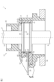
- FIG. 2 is a partial cross-sectional view along the axial direction of the sensor device of FIG. 1.
- FIG. FIG. 2 is a perspective view of a magnetic flux collector assembly that constitutes the sensor device of FIG. 1;
- 4 is a perspective view of a first magnetic flux collecting member and a second magnetic flux collecting member that constitute the magnetic flux collecting assembly of FIG. 3.
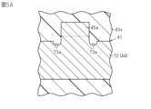
- FIG. FIG. 4 is an enlarged sectional view showing an example of a connecting portion between the first main body portion and the first claw portion in a state where molten resin is injected during insert molding of the resin holder that constitutes the magnetic flux collecting assembly of FIG. 3;
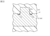
- FIG. 4 is an enlarged cross-sectional view showing an example of a connecting portion between the first main body portion and the first claw portion in a state where the molten resin is solidified during insert molding of the resin holder constituting the magnetic flux collecting assembly of FIG. 3;
- FIG. 2 is a plan view of a magnetic flux collecting assembly that constitutes the sensor device of FIG. 1;
- FIG. 4 is a perspective view of the magnetic flux collecting assembly constituting the sensor device of FIG. 1, seen from a different perspective from that of FIG. 3;
- the sensor device 1 is provided on the outer periphery of a rotating shaft 2.
- the rotating shaft 2 includes an input shaft 3 that is a first shaft, a torsion bar 4, and an output shaft 5 that is a second shaft.
- the input shaft 3 and the output shaft 5 are connected to each other via a torsion bar 4.
- the input shaft 3, torsion bar 4, and output shaft 5 are located on the same axis L.
- the rotating shaft 2 is, for example, a pinion shaft of a rack and pinion mechanism that constitutes a steering system of a vehicle.
- a steering wheel is connected to the upper end of the pinion shaft via an intermediate shaft and a column shaft.
- the sensor device 1 detects the torque applied to the rotating shaft 2 through the driver's operation of the steering wheel.
- the sensor device 1 includes a sensor magnet 11, a magnetic yoke assembly 12, and a fixing unit 13.
- the sensor magnet 11 is a cylindrical ring magnet.
- “cylindrical” may be considered to be cylindrical as a whole, and may also include a cylindrical shape formed by combining multiple parts, or a cylindrical shape with a cutout in a part like a C-shape. include.
- “Cylindrical” shapes include, but are not limited to, circles, ellipses, and polygons with sharp or rounded corners when viewed in the axial direction. In this embodiment, the sensor magnet 11 has a circular shape when viewed in the axial direction.
- the sensor magnet 11 is magnetized in the radial direction so that magnetic poles of different polarities are alternately arranged in the circumferential direction.
- the sensor magnet 11 is rotatably fixed to the outer peripheral surface of the input shaft 3 via a holder (not shown) or directly.
- the sensor magnet 11 may be a plurality of plate-shaped magnets.
- the magnetic yoke assembly 12 includes a first yoke core 21, a second yoke core 22, and a yoke holder 23 that holds the first yoke core 21 and the second yoke core 22.
- the magnetic yoke assembly 12 is arranged on the outer circumferential side of the sensor magnet 11 at intervals.
- the magnetic yoke assembly 12 is fixed to the outer periphery of the output shaft 5 so as to be rotatable therewith.
- Each of the first yoke core 21 and the second yoke core 22 is made of a magnetic material and has an annular shape.
- annular may be regarded as annular as a whole, and includes a ring formed by combining a plurality of parts, and a part having a notch, such as a C-shape.
- Annular shapes include, but are not limited to, circles, ellipses, and polygons with sharp or rounded corners when viewed in the axial direction.
- each of the first yoke core 21 and the second yoke core 22 has a circular shape when viewed in the axial direction.
- the first yoke core 21 and the second yoke core 22 are spaced apart from each other along the axis L.
- the first yoke core 21 and the second yoke core 22 each have a plurality of teeth 24 and 25.
- the teeth 24 and 25 protrude in a direction toward each other.
- the teeth 24 are provided at equal intervals in the circumferential direction with respect to the first yoke core 21, and the teeth 25 are provided with equal intervals in the circumferential direction with respect to the second yoke core 22.
- the tooth portions 24 and the tooth portions 25 are arranged alternately in the circumferential direction.
- the yoke holder 23 is made of, for example, a resin material and has a cylindrical shape. In this embodiment, the yoke holder 23 has a circular shape when viewed in the axial direction. The axial direction of the yoke holder 23 coincides with the direction along the axis L.
- the yoke holder 23 is a resin molded product formed by insert molding using the first yoke core 21 and the second yoke core 22 as insert products. That is, the yoke holder 23 is a portion of the magnetic yoke assembly 12 made of a resin material.
- the yoke holder 23 holds the first yoke core 21 and the second yoke core 22 on the axis L. Specifically, the yoke holder 23 holds the first yoke core 21 and the second yoke core 22 so that the inner surfaces of the teeth 24 and 25 are exposed on the inner peripheral side of the yoke holder 23.
- the fixed unit 13 includes a magnetic flux collection assembly 31, an outer case 32 that holds the magnetic flux collection assembly 31, and a circuit board 33.
- the fixed unit 13 is attached to a housing 34 that rotatably supports the rotating shaft 2.
- the housing 34 is, for example, a gear housing that accommodates the rack and pinion mechanism.
- the magnetic flux collection assembly 31 includes a first magnetic flux collection member 41, a second magnetic flux collection member 42, and a resin holder that holds the first magnetic flux collection member 41 and the second magnetic flux collection member 42. 43. Note that the magnetic flux collecting assembly 31 may further include a shield member disposed on the outer peripheral side of the first magnetic collecting member 41 and the second magnetic collecting member 42.
- the first magnetic flux collecting member 41 is arranged on the outer peripheral side of the first yoke core 21 at intervals.
- the first magnetic flux collecting member 41 includes an annular first main body part 44 that faces the first yoke core 21 in the radial direction, and two first claws that are bent from the first main body part 44 and protrude toward the outer circumferential side of the resin holder 43. It has portions 45a and 45b.
- the first main body portion 44 has a C-shape when viewed in the axial direction.
- the second magnetic flux collecting member 42 is arranged on the outer circumferential side of the second yoke core 22 at intervals.
- the second magnetic flux collecting member 42 includes an annular second main body portion 46 that faces the second yoke core 22 in the radial direction, and two second claws that are bent from the second main body portion 46 and protrude toward the outer circumferential side of the resin holder 43. It has portions 47a and 47b.
- the second main body portion 46 has a C-shape when viewed in the axial direction.
- opposite refers to surfaces or members that are in front of each other, and not only when they are completely in front of each other but also partially in front of each other. including cases.
- opposite in this specification refers to both a case where a member different from the two parts is interposed between the two parts, and a case where nothing is interposed between the two parts. including.
- the resin holder 43 has a generally cylindrical shape.
- the resin holder 43 is a resin molded product formed by insert molding using the first magnetic flux collecting member 41 and the second magnetic flux collecting member 42 as insert products.
- the resin holder 43 is a portion of the magnetic flux collecting assembly 31 made of a resin material. Details of the first magnetic flux collecting member 41, the second magnetic flux collecting member 42, and the resin holder 43 will be described later.
- the outer case 32 is a resin molded product formed by insert molding using the magnetic flux collecting assembly 31 as an insert product.
- the outer case 32 includes a case main body portion 51 that covers the outside of the magnetic flux collecting assembly 31, and a projecting portion 52 that projects outward in the radial direction of the magnetic flux collecting assembly 31.
- the case main body portion 51 has a generally cylindrical shape and is arranged on the axis L. That is, the case main body portion 51 is arranged coaxially with the magnetic flux collecting assembly 31.
- the projecting portion 52 has a cylindrical shape, for example, and projects in a direction perpendicular to the axis L. In this embodiment, the projecting portion 52 has a rectangular shape when viewed in a direction perpendicular to the axial direction.
- the open end of the projecting portion 52 is closed by a cover (not shown).
- Outer case 32 is fixed to housing 34. Thereby, the inside of the resin holder 43 is communicated with the inside of the housing 34 via the case body 51.
- the circuit board 33 has a rectangular plate shape.
- the circuit board 33 is placed within the overhang 52 .
- the circuit board 33 is electrically connected to a terminal (not shown) provided in the overhang 52.
- Two magnetic sensors 53a and 53b are mounted on the circuit board 33.
- One of the magnetic sensors 53a and 53b is a redundant sensor used when the other one malfunctions.
- the magnetic sensor 53a is mounted on the circuit board 33 so as to be disposed between the first claw part 45a of the first magnetism collecting member 41 and the second claw part 47a of the second magnetism collecting member 42.
- the magnetic sensor 53b is mounted on the circuit board 33 so as to be disposed between the first claw part 45b of the first magnetism collecting member 41 and the second claw part 47b of the second magnetism collecting member 42.
- the magnetic sensors 53a and 53b are for detecting the magnetic flux flowing through the first magnetic flux collecting member 41 and the second magnetic flux collecting member 42, and are, for example, Hall sensors or magnetoresistive sensors.
- the magnetic flux flowing through the first magnetic flux collecting member 41 and the second magnetic flux collecting member 42 also changes according to the change in the magnetic flux flowing through the first yoke core 21 and the second yoke core 22.
- the magnetic sensors 53a and 53b detect the magnetic flux flowing through the first magnetic flux collecting member 41 and the second magnetic flux collecting member 42, and generate a signal corresponding to this magnetic flux, that is, a signal indicating torque.
- insert molding is a molding technique in which injection molding is performed with an insert product placed inside a mold.
- injection molding is performed with the first magnetic flux collecting member 41 and the second magnetic flux collecting member 42 arranged inside a mold.
- the first magnetic flux collecting member 41 and the second magnetic flux collecting member 42 are surrounded by the molten resin injected into the mold.
- this molten resin is cooled and solidified to form a resin holder 43 which is a resin molded product.
- a molding shrinkage phenomenon usually occurs.
- This phenomenon is a phenomenon in which the volume of the molten resin filled inside the mold decreases when it is cooled and solidified. Therefore, due to the molding shrinkage phenomenon, a slight gap may occur between the first magnetic flux collecting member 41 and the second magnetic flux collecting member 42 and the resin holder 43.
- the resin holder 43 has a sharp shape, the sharp part is more likely to separate from the first magnetic flux collecting member 41 and the second magnetic collecting member 42 than the flat part, and there is a gap. is likely to occur.
- the first claw portion 45a of the first magnetic flux collecting member 41 is bent from the first main body portion 44. Therefore, as shown in FIGS. 5A and 5B, for example, when looking locally at the vicinity of the connecting portion between the first main body portion 44 and the first claw portion 45a, the space filled by the resin holder 43 has a sharp shape. In other words, the resin holder 43 has a locally sharp shape near the connecting portion between the first main body portion 44 and the first claw portion 45a.
- the first magnetic flux collecting member 41 of this embodiment has the first recess 73a adjacent to the first claw 45a, the relationship between the first main body 44 and the first claw 45a in the resin holder 43 is The shape near the connecting portion tends to become even more sharp. The same can be said of the connecting portion between the first main body portion 44 and the first claw portion 45a, and the connecting portion between the second main body portion 46 and the second claw portions 47a and 47b in the second magnetic flux collecting member 42.
- the resin holder 43 has a connecting portion between the first main body portion 44 and the first claw portions 45a, 45b, and a connecting portion between the second main body portion 46 and the second claw portions 47a, 47b.
- the first magnetic flux collecting member 41 and the second magnetic flux collecting member 42 are held so as not to be exposed to the inner peripheral surface.
- the configurations of the resin holder 43, the first magnetic flux collecting member 41, and the second magnetic flux collecting member 42 will be described in detail.
- the resin holder 43 includes a cylindrical holder body 61, and a first support wall 62 and a second support wall 63 provided on the outer peripheral surface of the holder body 61.
- the holder main body 61 has a circular shape when viewed in the axial direction.
- the first support wall 62 projects radially outward from one axial end of the holder main body 61 .
- the second support wall 63 projects radially outward from the other axial end of the holder main body 61 .
- the first support wall 62 faces the second support wall 63 with an interval in the axial direction.
- the first magnetic flux collecting member 41 is formed by bending a long metal plate made of a magnetic material. That is, the first magnetic flux collecting member 41 is one piece.
- the first main body portion 44 of the first magnetic flux collecting member 41 has a first circular arc portion 71 and a first protrusion portion 72 .
- the first arc portion 71 has an arcuate inner circumferential surface that coincides with the inner circumferential surface of the holder main body 61, that is, the inner circumferential surface of the resin holder 43 when viewed in the axial direction.
- a circle formed by extending the inner circumferential surface of the first circular arc portion 71 is defined as a first virtual circle C1.
- a line indicating the first virtual circle C1 coincides with a line indicating the inner circumferential surface of the resin holder 43.
- the first protruding portion 72 protrudes from, for example, the circumferential center of the first circular arc portion 71 toward the outer circumferential side so as to be disposed on the outer circumferential side of the first virtual circle C1.
- the first protruding portion 72 has a connecting portion bent radially outward from the end of the first circular arc portion 71 and a straight portion extending linearly between the connecting portions.
- the first claw portions 45a, 45b are bent radially outward from the straight portion of the first protrusion 72 and protrude toward the outer circumferential side of the resin holder 43.
- First recesses 73a and 73b are provided on both sides of each of the first claws 45a and 45b in the first protrusion 72. As shown in FIG.
- the first main body portion 44 has first recesses 73a, 73b on both sides in the circumferential direction of the resin holder 43 at respective connecting portions with the first claw portions 45a, 45b.
- Each of the first recesses 73a and 73b extends linearly along the thickness direction of the first protrusion 72, and is open to the inner circumferential side and the outer circumferential side of the first main body portion 44.
- the entire inner circumferential surface of the first circular arc portion 71 is exposed to the inner circumferential surface of the resin holder 43, and the first protrusion The entire portion 72 is held in the resin holder 43 in such a manner that it is embedded inside the resin holder 43.
- a portion of the inner circumferential surface of the first circular arc portion 71 may be embedded inside the resin holder 43.
- the inner circumferential surface of the first circular arc portion 71 in this embodiment is exposed so that there is no step between it and the inner circumferential surface of the resin holder 43.
- the inner circumferential surface of the first circular arc portion 71 is It may also protrude toward the inner peripheral side of the resin holder 43. Furthermore, if the connecting portion between the first main body portion 44 and the first claw portions 45a and 45b is embedded inside the resin holder 43, a part of the first protrusion portion 72 is exposed to the outside of the resin holder 43. Good too. As shown in FIG. 3, the first claw portions 45a and 45b are exposed on the surface of the first support wall 62 that faces the second support wall 63. As shown in FIG.
- the second magnetic flux collecting member 42 has the same shape as the first magnetic flux collecting member 41, and is formed by bending a long metal plate made of a magnetic material. In other words, the second magnetic flux collecting member 42 is an integral piece.
- the second main body portion 46 of the second magnetic flux collecting member 42 has a second circular arc portion 81 and a second protrusion portion 82 .
- the second arcuate portion 81 has an arcuate inner circumferential surface that matches the inner circumferential surface of the resin holder 43 when viewed in the axial direction.
- the second circular arc portion 81 has the same shape as the first circular arc portion 71.
- a circle formed by extending the inner circumferential surface of the second circular arc portion 81 is defined as a second virtual circle C2.
- the second virtual circle C2 coincides with the first virtual circle C1.
- the second protruding portion 82 protrudes from, for example, the circumferential center of the second circular arc portion 81 toward the outer circumferential side so as to be disposed on the outer circumferential side of the second virtual circle C2.
- the second protruding portion 82 has a connecting portion bent radially outward from the end of the second circular arc portion 81 and a straight portion extending linearly between the connecting portions.
- the second claw portions 47a and 47b are bent radially outward from the straight portion of the second protrusion 82 and protrude toward the outer circumferential side of the resin holder 43.
- Second recesses 83a and 83b are provided on both sides of each of the second claws 47a and 47b in the second protrusion 82. As shown in FIG.
- the second main body portion 46 has second recesses 83a, 83b on both sides in the circumferential direction of the resin holder 43 at respective connecting portions with the second claw portions 47a, 47b.
- Each of the second recesses 83a and 83b extends linearly along the thickness direction of the second protrusion 82, and is open to the inner circumferential side and the outer circumferential side of the second main body portion 46.
- the entire inner circumferential surface of the second circular arc portion 81 is exposed to the inner circumferential surface of the resin holder 43, and the second protrusion The entire portion 82 is held by the resin holder 43 in such a manner that it is embedded inside the resin holder 43.
- a portion of the inner circumferential surface of the second circular arc portion 81 may be embedded inside the resin holder 43.
- the inner circumferential surface of the second circular arc portion 81 in this embodiment is exposed so that there is no step between it and the inner circumferential surface of the resin holder 43.
- the inner circumferential surface of the second circular arc portion 81 is It may also protrude toward the inner peripheral side of the resin holder 43. Furthermore, if the connecting portion between the second main body part 46 and the second claw parts 47a and 47b is embedded inside the resin holder 43, a part of the second protrusion part 82 will be exposed to the outside of the resin holder 43. Good too. As shown in FIG. 3, the second claw parts 47a, 47b are exposed on the surface of the second support wall 63 facing the first support wall 62 so as to face the first claw parts 45a, 45b in the axial direction. ing.
- connection portion between the first body portion 44 and the first claw portions 45a, 45b and the connection portion between the second body portion 46 and the second claw portions 47a, 47b are located on the inner periphery of the resin holder 43.
- the first magnetic flux collecting member 41 and the second magnetic flux collecting member 42 are held so that they are not exposed to the surface. Therefore, even if a gap occurs between the resin holder 43 and the connecting portion of the first main body portion 44 with the first claw portion 45a due to molding shrinkage, for example, there is no gap on the inner peripheral surface of the resin holder 43. is less likely to occur. Thereby, even if liquid intrudes into the resin holder 43, it is possible to prevent the liquid from reaching the magnetic sensors 53a, 53b.
- the first main body portion 44 has a first arc portion 71 and a first protrusion portion 72.
- the circle formed by extending the first circular arc portion 71 is the first virtual circle C1.
- the first protruding portion 72 protrudes from the first circular arc portion 71 so as to be disposed on the outer peripheral side of the first virtual circle C1.
- the first claws 45a and 45b protrude from the first protrusion 72 toward the outer circumferential side of the resin holder 43.
- the resin holder 43 holds the first magnetic flux collecting member 41 such that the first circular arc portion 71 is exposed on the inner peripheral surface of the resin holder 43 and the first protrusion portion 72 is embedded inside the resin holder 43.
- the first circular arc that is a part of the first main body part 44 is The portion 71 can be exposed on the inner peripheral surface of the resin holder 43. Therefore, for example, compared to the case where the first main body part 44 is entirely buried inside the resin holder 43, the first main body part 44 can be arranged closer to the first yoke core 21, and the first magnetic flux collecting member 41 can be placed closer to the first yoke core 21. Decrease in flowing magnetic flux can be suppressed. Thereby, it is possible to suppress the absolute value of the magnetic flux detected by the magnetic sensors 53a and 53b from becoming small, and to suppress the deterioration of the noise resistance performance.
- the second main body portion 46 has a second circular arc portion 81 and a second protrusion portion 82.
- the circle formed by extending the second circular arc portion 81 is the second virtual circle C2.
- the second protruding portion 82 protrudes from the second circular arc portion 81 so as to be disposed on the outer peripheral side of the second virtual circle C2.
- the second claw portions 47a and 47b protrude from the second protrusion 82 toward the outer circumferential side of the resin holder 43.
- the resin holder 43 holds the second magnetic flux collecting member 42 such that the second circular arc portion 81 is exposed on the inner peripheral surface of the resin holder 43 and the second protrusion 82 is embedded inside the resin holder 43.
- the same effect as in (2) above can be applied to the second magnetic flux collecting member 42 as well. Thereby, it is possible to suppress the absolute value of the magnetic flux detected by the magnetic sensors 53a and 53b from becoming small, and to suppress the deterioration of the noise resistance performance.
- Each of the first magnetic flux collecting member 41 and the second magnetic flux collecting member 42 is an integral product. Therefore, compared to, for example, a case where a magnetic flux collecting member is formed by joining a plurality of parts, an increase in the number of parts can be suppressed.
- the first main body portion 44 has first recesses 73a, 73b on both sides in the circumferential direction of the resin holder 43 at respective connecting portions with the first claw portions 45a, 45b.
- the second body portion 46 has second recesses 83a, 83b on both sides in the circumferential direction of the resin holder 43 at respective connecting portions with the second claw portions 47a, 47b.
- the first body part 44 (strictly speaking, the first protruding part 72) is provided with the first recesses 73a and 73b, when bending the first claw parts 45a and 45b, the first body part 44 can be prevented from being pulled and bent by the first claws 45a and 45b. This facilitates bending of the first claw portions 45a, 45b. Similarly, bending of the second claw portions 47a, 47b becomes easier.
- the first magnetic flux collecting member 41 has the first recesses 73a and 73b, the shape of the resin holder 43 in the vicinity of the connecting portion between the first main body portion 44 and the first claw portions 45a and 45b is further improved. It tends to become more pointed (see FIGS. 5A and 5B). The same thing can be said about the second magnetic flux collecting member 42. Therefore, a configuration is adopted in which the connecting portion between the first main body portion 44 and the first claw portions 45a, 45b and the connecting portion between the second main body portion 46 and the second claw portions 47a, 47b are not exposed to the inner circumferential surface of the resin holder 43. The effects of adopting it are significant.
- the first magnetic flux collecting member 41 has the same shape as the second magnetic flux collecting member 42. Therefore, compared to the case where the first magnetic flux collecting member 41 has a different shape from the second magnetic flux collecting member 42, the manufacturing cost can be reduced.
- This embodiment can be modified and implemented as follows. This embodiment and the following modified examples can be implemented in combination with each other within a technically consistent range. -
- the first magnetic flux collecting member 41 does not need to have the first recesses 73a and 73b.
- the second magnetic flux collecting member 42 does not need to have the second recesses 83a and 83b.
- the first magnetic flux collecting member 41 does not have to be an integral part.
- the members forming the first claw portions 45a and 45b may be separately joined to the member forming the first body portion 44.
- the second magnetic flux collecting member 42 does not have to be an integral part.
- the shape of the first main body portion 44 can be changed as appropriate.
- the first main body portion 44 may not have the first protruding portion 72 and may have only the first circular arc portion 71.
- the resin holder 43 holds the first magnetic flux collecting member 41 eccentrically from the axis L, thereby connecting the first main body portion 44 (first arc portion 71) and the first claw portions 45a, 45b. The portion is not exposed to the inner peripheral surface of the resin holder 43.
- the first arc portion 71 may have an arcuate inner circumferential surface that does not match the inner circumferential surface of the resin holder 43 when viewed in the axial direction, for example.
- the first protrusion 72 may not have a straight portion, for example, and the entire first protrusion 72 may be curved.
- the shape of the second main body portion 46 can be changed as appropriate.
- the first magnetic flux collecting member 41 may have only one first claw portion.
- the second magnetic flux collecting member 42 may have only one second claw portion.
- the first magnetic flux collecting member 41 may have a different shape from the second magnetic flux collecting member 42.
- the first main body portion 44 may face the first yoke core 21 in the axial direction.
- the first main body portion 44 may have a flat plate shape, for example, and its shape can be changed as appropriate.
- the second magnetic flux collecting member 42 may face the second yoke core 22 in the axial direction.
- the resin holder 43 may have only the holder body 61 without the first support wall 62 and the second support wall 63.
- the rotating shaft 2 may be a shaft other than a pinion shaft, such as a column shaft. That is, the sensor device 1 may be provided around the column shaft, for example.
- the sensor device 1 does not need to include the outer case 32. Further, the sensor device 1 does not need to include the circuit board 33 as long as it includes the magnetic sensors 53a and 53b. Furthermore, the sensor device 1 may include only one magnetic sensor.
- the sensor device 1 may be configured to detect the rotation angle of the rotating shaft 2 in addition to the torque.
- the sensor device 1 further includes a driving gear provided on the magnetic yoke assembly 12, for example, and one or more driven gears meshing with the driving gear. Then, the rotation angle of the rotary shaft 2 can be detected based on the rotation angle of the driven gear.
- the sensor magnet 11 is fixed to the input shaft 3 and the magnetic yoke assembly 12 is fixed to the output shaft 5
- the sensor magnet 11 may be fixed to the output shaft 5 and the magnetic yoke assembly 12 may be fixed to the input shaft 3.
Landscapes
- Physics & Mathematics (AREA)
- General Physics & Mathematics (AREA)
- Electromagnetism (AREA)
- Power Steering Mechanism (AREA)
- Transmission And Conversion Of Sensor Element Output (AREA)
Priority Applications (5)
| Application Number | Priority Date | Filing Date | Title |
|---|---|---|---|
| JP2024508845A JP7810253B2 (ja) | 2022-03-22 | 2022-03-22 | センサ装置 |
| CN202280093382.XA CN118900990A (zh) | 2022-03-22 | 2022-03-22 | 传感器装置 |
| EP22933263.0A EP4498055A4 (en) | 2022-03-22 | 2022-03-22 | SENSOR DEVICE |
| PCT/JP2022/013157 WO2023181116A1 (ja) | 2022-03-22 | 2022-03-22 | センサ装置 |
| US18/846,018 US20250189389A1 (en) | 2022-03-22 | 2022-03-22 | Sensor device |
Applications Claiming Priority (1)
| Application Number | Priority Date | Filing Date | Title |
|---|---|---|---|
| PCT/JP2022/013157 WO2023181116A1 (ja) | 2022-03-22 | 2022-03-22 | センサ装置 |
Publications (1)
| Publication Number | Publication Date |
|---|---|
| WO2023181116A1 true WO2023181116A1 (ja) | 2023-09-28 |
Family
ID=88100215
Family Applications (1)
| Application Number | Title | Priority Date | Filing Date |
|---|---|---|---|
| PCT/JP2022/013157 Ceased WO2023181116A1 (ja) | 2022-03-22 | 2022-03-22 | センサ装置 |
Country Status (5)
| Country | Link |
|---|---|
| US (1) | US20250189389A1 (https=) |
| EP (1) | EP4498055A4 (https=) |
| JP (1) | JP7810253B2 (https=) |
| CN (1) | CN118900990A (https=) |
| WO (1) | WO2023181116A1 (https=) |
Citations (6)
| Publication number | Priority date | Publication date | Assignee | Title |
|---|---|---|---|---|
| JP2011232318A (ja) * | 2010-04-07 | 2011-11-17 | Jtekt Corp | 集磁リング及びその製造方法並びにトルクセンサ及び電動パワーステアリング装置 |
| CN202188930U (zh) * | 2011-08-01 | 2012-04-11 | 杭州万向传动轴有限公司 | 一种新型电动转向扭矩装置 |
| JP2018059805A (ja) * | 2016-10-05 | 2018-04-12 | Kyb株式会社 | トルクセンサ |
| JP2020034422A (ja) * | 2018-08-30 | 2020-03-05 | 株式会社ジェイテクト | センサ装置 |
| JP2020034398A (ja) * | 2018-08-29 | 2020-03-05 | 株式会社ジェイテクト | センサ装置 |
| JP2021025819A (ja) | 2019-08-01 | 2021-02-22 | 日立金属株式会社 | センサ装置 |
Family Cites Families (2)
| Publication number | Priority date | Publication date | Assignee | Title |
|---|---|---|---|---|
| JP6056458B2 (ja) * | 2012-12-25 | 2017-01-11 | 株式会社ジェイテクト | トルク検出装置、および同装置を備えるステアリング装置 |
| JP2018179701A (ja) * | 2017-04-11 | 2018-11-15 | Kyb株式会社 | 磁気検出装置、トルクセンサ及び電動パワーステアリング装置 |
-
2022
- 2022-03-22 US US18/846,018 patent/US20250189389A1/en active Pending
- 2022-03-22 JP JP2024508845A patent/JP7810253B2/ja active Active
- 2022-03-22 WO PCT/JP2022/013157 patent/WO2023181116A1/ja not_active Ceased
- 2022-03-22 EP EP22933263.0A patent/EP4498055A4/en active Pending
- 2022-03-22 CN CN202280093382.XA patent/CN118900990A/zh active Pending
Patent Citations (6)
| Publication number | Priority date | Publication date | Assignee | Title |
|---|---|---|---|---|
| JP2011232318A (ja) * | 2010-04-07 | 2011-11-17 | Jtekt Corp | 集磁リング及びその製造方法並びにトルクセンサ及び電動パワーステアリング装置 |
| CN202188930U (zh) * | 2011-08-01 | 2012-04-11 | 杭州万向传动轴有限公司 | 一种新型电动转向扭矩装置 |
| JP2018059805A (ja) * | 2016-10-05 | 2018-04-12 | Kyb株式会社 | トルクセンサ |
| JP2020034398A (ja) * | 2018-08-29 | 2020-03-05 | 株式会社ジェイテクト | センサ装置 |
| JP2020034422A (ja) * | 2018-08-30 | 2020-03-05 | 株式会社ジェイテクト | センサ装置 |
| JP2021025819A (ja) | 2019-08-01 | 2021-02-22 | 日立金属株式会社 | センサ装置 |
Non-Patent Citations (1)
| Title |
|---|
| See also references of EP4498055A4 |
Also Published As
| Publication number | Publication date |
|---|---|
| CN118900990A (zh) | 2024-11-05 |
| EP4498055A1 (en) | 2025-01-29 |
| US20250189389A1 (en) | 2025-06-12 |
| JPWO2023181116A1 (https=) | 2023-09-28 |
| EP4498055A4 (en) | 2025-05-21 |
| JP7810253B2 (ja) | 2026-02-03 |
Similar Documents
| Publication | Publication Date | Title |
|---|---|---|
| EP2860504B1 (en) | Torque index sensor | |
| US7509883B2 (en) | Torque detecting apparatus and manufacturing method thereof | |
| JP7103498B2 (ja) | 検出装置 | |
| EP2833110B1 (en) | Torque detecting device and electric power steering system | |
| EP2626987B1 (en) | Sensing magnet apparatus for motor | |
| US8806962B2 (en) | Torque detection device and electric power steering system including the same | |
| CN105593106A (zh) | 扭矩传感器 | |
| CN106794871B (zh) | 转矩传感器装置 | |
| JP2013524207A (ja) | トルク測定装置及びこれを含む車両用操向装置 | |
| EP3009802B1 (en) | Sensing device and method for manufacturing sensing device | |
| KR102490684B1 (ko) | 밸브 액추에이터 | |
| JP2018072086A (ja) | 回転角検出装置 | |
| CN105745824B (zh) | 具备发动机控制用信号的输出功能的起动发电机 | |
| JP2014092446A (ja) | トルクセンサ、駆動ユニットおよび電動アシスト自転車 | |
| WO2023181116A1 (ja) | センサ装置 | |
| CN106794872A (zh) | 转矩传感器装置 | |
| JP7021957B2 (ja) | トルクセンサ | |
| JP2008241564A (ja) | 舵角検出装置及びステアリング装置 | |
| JP2023132532A (ja) | 電動パワーステアリング装置 | |
| JP4626318B2 (ja) | 回転検出センサ | |
| JP2019200135A (ja) | トルク検出装置および電動パワーステアリング装置 | |
| JP2021012077A (ja) | センサ装置 | |
| CN118302318A (zh) | 轮毂电机 | |
| CN118251326A (zh) | 轮毂电机 | |
| WO2024121996A1 (ja) | トルクセンサ |
Legal Events
| Date | Code | Title | Description |
|---|---|---|---|
| 121 | Ep: the epo has been informed by wipo that ep was designated in this application |
Ref document number: 22933263 Country of ref document: EP Kind code of ref document: A1 |
|
| ENP | Entry into the national phase |
Ref document number: 2024508845 Country of ref document: JP Kind code of ref document: A |
|
| WWE | Wipo information: entry into national phase |
Ref document number: 202280093382.X Country of ref document: CN |
|
| WWE | Wipo information: entry into national phase |
Ref document number: 18846018 Country of ref document: US |
|
| WWE | Wipo information: entry into national phase |
Ref document number: 2022933263 Country of ref document: EP |
|
| NENP | Non-entry into the national phase |
Ref country code: DE |
|
| ENP | Entry into the national phase |
Ref document number: 2022933263 Country of ref document: EP Effective date: 20241022 |
|
| WWP | Wipo information: published in national office |
Ref document number: 18846018 Country of ref document: US |