WO2023181106A1 - ダイヤモンド被覆体 - Google Patents
ダイヤモンド被覆体 Download PDFInfo
- Publication number
- WO2023181106A1 WO2023181106A1 PCT/JP2022/013083 JP2022013083W WO2023181106A1 WO 2023181106 A1 WO2023181106 A1 WO 2023181106A1 JP 2022013083 W JP2022013083 W JP 2022013083W WO 2023181106 A1 WO2023181106 A1 WO 2023181106A1
- Authority
- WO
- WIPO (PCT)
- Prior art keywords
- diamond
- groove
- coating layer
- base material
- coated body
- Prior art date
- Legal status (The legal status is an assumption and is not a legal conclusion. Google has not performed a legal analysis and makes no representation as to the accuracy of the status listed.)
- Ceased
Links
Images



Classifications
-
- C—CHEMISTRY; METALLURGY
- C23—COATING METALLIC MATERIAL; COATING MATERIAL WITH METALLIC MATERIAL; CHEMICAL SURFACE TREATMENT; DIFFUSION TREATMENT OF METALLIC MATERIAL; COATING BY VACUUM EVAPORATION, BY SPUTTERING, BY ION IMPLANTATION OR BY CHEMICAL VAPOUR DEPOSITION, IN GENERAL; INHIBITING CORROSION OF METALLIC MATERIAL OR INCRUSTATION IN GENERAL
- C23C—COATING METALLIC MATERIAL; COATING MATERIAL WITH METALLIC MATERIAL; SURFACE TREATMENT OF METALLIC MATERIAL BY DIFFUSION INTO THE SURFACE, BY CHEMICAL CONVERSION OR SUBSTITUTION; COATING BY VACUUM EVAPORATION, BY SPUTTERING, BY ION IMPLANTATION OR BY CHEMICAL VAPOUR DEPOSITION, IN GENERAL
- C23C16/00—Chemical coating by decomposition of gaseous compounds, without leaving reaction products of surface material in the coating, i.e. chemical vapour deposition [CVD] processes
- C23C16/22—Chemical coating by decomposition of gaseous compounds, without leaving reaction products of surface material in the coating, i.e. chemical vapour deposition [CVD] processes characterised by the deposition of inorganic material, other than metallic material
- C23C16/26—Deposition of carbon only
- C23C16/27—Diamond only
-
- C—CHEMISTRY; METALLURGY
- C30—CRYSTAL GROWTH
- C30B—SINGLE-CRYSTAL GROWTH; UNIDIRECTIONAL SOLIDIFICATION OF EUTECTIC MATERIAL OR UNIDIRECTIONAL DEMIXING OF EUTECTOID MATERIAL; REFINING BY ZONE-MELTING OF MATERIAL; PRODUCTION OF A HOMOGENEOUS POLYCRYSTALLINE MATERIAL WITH DEFINED STRUCTURE; SINGLE CRYSTALS OR HOMOGENEOUS POLYCRYSTALLINE MATERIAL WITH DEFINED STRUCTURE; AFTER-TREATMENT OF SINGLE CRYSTALS OR A HOMOGENEOUS POLYCRYSTALLINE MATERIAL WITH DEFINED STRUCTURE; APPARATUS THEREFOR
- C30B29/00—Single crystals or homogeneous polycrystalline material with defined structure characterised by the material or by their shape
- C30B29/02—Elements
- C30B29/04—Diamond
Definitions
- the present invention relates to a diamond-coated body in which a diamond coating layer is formed on the surface of a base material.
- diamond-coated bodies in which a diamond coating layer is formed on the surface of a base material, have been used for members such as tools that require wear-resistant performance.
- the area formed within the groove in the coating layer may be damaged due to the influence of residual stress around the groove, resulting in a problem that the coating layer may peel off.
- the above-mentioned problems are not preferable because they shorten the life of the tool.
- the present disclosure has been made to solve such problems, and is to provide a technique for preventing the occurrence of defects in diamond-coated bodies.
- a first aspect includes: a base material made of a material having a larger coefficient of thermal expansion than diamond and having a surface area extending along a first direction and a second direction that intersect with each other; a plurality of grooves extending along the first direction and spaced apart in the second direction in the surface region of the substrate; and a plurality of grooves formed of diamond as a material;
- the present invention is a diamond-coated body comprising a coating layer to be coated and a low-density portion formed on the back side of each of the grooves and having a lower density of diamond than the coating layer.
- the low-density portion is formed as a void in which diamond does not exist.
- the low-density portion occupies 10% to 80% of the area of the groove in a cross-sectional view along a direction intersecting the first direction.
- the coating layer is a layer formed by a vapor phase growth method, and the groove portions each have a thickness t of the coating layer in a cross-sectional view along a direction intersecting the first direction.
- the surface area of the base material in each of the imaginary circles and The groove width w corresponds to the distance between the contact points of the base material, and the groove width w is such that the groove width w is between the virtual line from the contact point with the surface area of the base material to the center in the virtual circle and the second direction.
- the range is defined by the formula [w ⁇ t+t ⁇ cos ⁇ ] based on the forming angle ⁇ .
- the base material is made of cemented carbide and is used for a tool having a rake face and a flank face, and the groove portion and the coating layer are formed on a surface that becomes the rake face. formed in the area.
- the diamond-coated body of each of the above aspects includes a low-density portion in which the density of diamond is lower than that of the coating layer on the inner side of each groove.
- This low-density area of the coating layer is more likely to contract due to pressure from the surrounding area than the area formed within the groove, so even if residual stress is generated around the groove, the area will shrink in response to this and cause residual stress. can be alleviated. As a result, it is possible to prevent the region of the coating layer formed within the groove from being damaged due to the influence of residual stress generated around the groove, thereby preventing the coating layer from peeling off.
- a perspective view of a diamond coating in an embodiment of the present disclosure Front view of a diamond coated body in an embodiment of the present disclosure
- a perspective view of a base material in an embodiment of the present disclosure Front sectional view of a groove in an embodiment of the present disclosure
- Front sectional view of a groove in another embodiment of the present disclosure A front cross-sectional view showing how the low-density portion contracts in an embodiment of the present disclosure
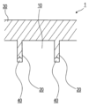
- the diamond coated body 1 includes a base material 10 made of a material with a larger coefficient of thermal expansion than diamond, and a diamond coating formed on the surface area of the base material 10. It includes a plurality of grooves 20, a coating layer 30 that covers the surface area of the base material 10 together with each of the grooves 20, and a low-density portion 40 formed on the back side of each of the grooves 20.
- the base material 10 has a surface area that extends along a first direction and a second direction that intersect with each other.
- the base material 10 is used as a tool having a flank surface 11 and a rake surface 13, and the rake surface 13 extends along the first direction and the second direction. It forms a surface area that spreads out.
- the base material 10 in this embodiment is made of cemented carbide.
- the grooves 20 extend along the first direction on the rake face 13 of the base material 10 and are formed at intervals in the second direction.
- the groove portion 20 is formed as a groove extending straight in a third direction intersecting the rake face 13.
- the groove portion 20 is formed by scanning a femtosecond laser with a predetermined output along the surface of the base material 10.
- the groove 20 is formed by forming two virtual circles C each having a diameter equal to the thickness t of the coating layer 30 in a cross-sectional view along a direction intersecting the first direction.
- the groove width w is based on the angle ⁇ formed between an imaginary line extending from the contact point p1 with the rake surface 13 of the base material 10 to the center p2 in the imaginary circle C and an axis extending in the second direction.
- the range is defined by the formula [w ⁇ t+t ⁇ cos ⁇ ].
- the coating layer 30 is made of diamond and covers the rake face 13 of the base material 10 along with each of the grooves 20. This covering layer 30 is formed to fill the groove 20 to a predetermined depth. In this embodiment, the coating layer 30 is formed to have a thickness of 1 to 50 ⁇ m (preferably 30 ⁇ m or less).
- the low-density portion 40 is formed at the back side of each groove portion 20 as a region where the density of diamond is lower than that of the coating layer 30.
- the low density portion 40 is formed as a void in which no diamond is present.
- the low-density portion 40 occupies 10% to 80% (preferably 20 to 70%) of the area of the groove portion 20 in a cross-sectional view along the direction intersecting the first direction.
- the coating layer 30 is formed by applying diamond particles to the surface region of the base material 10 and then applying a vapor phase growth method (specifically, a microwave plasma CVD method or the like) to this surface region.
- a vapor phase growth method specifically, a microwave plasma CVD method or the like
- This is a diamond layer deposited by hot filament CVD (hot filament CVD, etc.).
- a predetermined surface treatment such as etching is performed on the surface region of the base material 10 in which the groove portion 20 is formed.
- the covering layer 30 closes the groove portion 20 in the process of reaching the specified film thickness t.
- the groove 20 since the groove 20 has the above-mentioned groove width w, the groove 20 is closed before the coating layer 30 fills the entire groove 20, so that no diamond is present on the deep side of the groove 20. A low density portion 40 as a void is formed.
- the surface of the diamond coated body 1 on which the coating layer 30 is formed is smoothed according to the required performance as a tool. For smoothing here, a method of displacing the laser irradiation area along the surface of the coating layer 30 (for example, the laser processing method described in Japanese Patent No. 6,562,536; Pulse Laser Grinding) is adopted.
- the diamond coated body 1 is formed by forming the coating layer 30 on a tool having the flank face 11 and the rake face 13 as the base material 10.
- the diamond coated body 1 may be one in which a coating layer 30 is formed on a base material 10 that is used as something other than a tool.
- the groove portion 20 is formed as a groove extending straight in the third direction intersecting the rake face 13.
- the groove portion 20 may be formed as a V-shaped groove in which the groove width w gradually narrows in the depth direction, as shown in FIGS. 5(a) and 5(b).
- the low density portion 40 is formed as a void where no diamond exists.
- the low density portion 40 may be formed of a component having a lower Young's modulus than the material of the base material 10.
- each of the groove portions 20 extends along the first direction, that is, is formed as one groove extending in the first direction.
- the groove portion 20 does not necessarily have to be formed as a single groove, and by forming a plurality of grooves and holes respectively along the first direction, a pseudo groove extending in the first direction as a whole can be formed. It may be .
- the diamond-coated body 1 of the above embodiment includes a low-density portion 40 in which the density of diamond is lower than that of the coating layer 30 on the inner side of each groove portion 20 .
- This low-density portion 40 is more likely to contract due to pressure from the surrounding area than the area formed within the groove portion 20 in the coating layer 30, so even if residual stress is generated around the groove portion 20, the low-density portion 40 will contract in response to this. Residual stress can be alleviated by this (see FIG. 6).
- the present applicant has proposed that when the low density portion 40 occupies 10% to 80% (preferably 20 to 70%) of the area of the groove portion 20 in a cross-sectional view along the direction intersecting the first direction, It has been discovered that the residual stress caused by the low density portions 40 can be alleviated while improving the adhesion between the base material 10 and the coating layer 30 due to the groove portions 20. Therefore, in the diamond-coated body 1 of the above embodiment, it is possible to improve the adhesion between the base material 10 and the coating layer 30 by the groove portions 20 and to alleviate residual stress by the low-density portion 40.
- the diamond-coated body of the present invention can be used for members such as tools that require wear-resistant performance.
Landscapes
- Chemical & Material Sciences (AREA)
- Engineering & Computer Science (AREA)
- Materials Engineering (AREA)
- Metallurgy (AREA)
- Organic Chemistry (AREA)
- Inorganic Chemistry (AREA)
- General Chemical & Material Sciences (AREA)
- Chemical Kinetics & Catalysis (AREA)
- Mechanical Engineering (AREA)
- Crystallography & Structural Chemistry (AREA)
- Chemical Vapour Deposition (AREA)
- Cutting Tools, Boring Holders, And Turrets (AREA)
Priority Applications (2)
| Application Number | Priority Date | Filing Date | Title |
|---|---|---|---|
| PCT/JP2022/013083 WO2023181106A1 (ja) | 2022-03-22 | 2022-03-22 | ダイヤモンド被覆体 |
| JP2024508837A JPWO2023181106A1 (https=) | 2022-03-22 | 2022-03-22 |
Applications Claiming Priority (1)
| Application Number | Priority Date | Filing Date | Title |
|---|---|---|---|
| PCT/JP2022/013083 WO2023181106A1 (ja) | 2022-03-22 | 2022-03-22 | ダイヤモンド被覆体 |
Publications (1)
| Publication Number | Publication Date |
|---|---|
| WO2023181106A1 true WO2023181106A1 (ja) | 2023-09-28 |
Family
ID=88100208
Family Applications (1)
| Application Number | Title | Priority Date | Filing Date |
|---|---|---|---|
| PCT/JP2022/013083 Ceased WO2023181106A1 (ja) | 2022-03-22 | 2022-03-22 | ダイヤモンド被覆体 |
Country Status (2)
| Country | Link |
|---|---|
| JP (1) | JPWO2023181106A1 (https=) |
| WO (1) | WO2023181106A1 (https=) |
Citations (5)
| Publication number | Priority date | Publication date | Assignee | Title |
|---|---|---|---|---|
| JPH05311442A (ja) * | 1992-03-11 | 1993-11-22 | Showa Denko Kk | ダイヤモンド薄膜形成法 |
| WO1996034131A1 (fr) * | 1995-04-24 | 1996-10-31 | Toyo Kohan Co., Ltd. | Articles possedant un revetement en diamant forme par synthese en phase vapeur |
| JPH10337602A (ja) * | 1997-06-04 | 1998-12-22 | Mitsubishi Materials Corp | 厚膜化人工ダイヤモンド被覆層がすぐれた耐剥離性を有する表面被覆超硬合金製切削工具 |
| JPH1112736A (ja) * | 1997-06-27 | 1999-01-19 | Mitsubishi Materials Corp | 厚膜化人工ダイヤモンド被覆層がすぐれた耐剥離性を有する表面被覆超硬合金製切削工具 |
| JPH11199379A (ja) * | 1998-01-16 | 1999-07-27 | Kobe Steel Ltd | ダイヤモンド膜の形成方法 |
-
2022
- 2022-03-22 JP JP2024508837A patent/JPWO2023181106A1/ja active Pending
- 2022-03-22 WO PCT/JP2022/013083 patent/WO2023181106A1/ja not_active Ceased
Patent Citations (5)
| Publication number | Priority date | Publication date | Assignee | Title |
|---|---|---|---|---|
| JPH05311442A (ja) * | 1992-03-11 | 1993-11-22 | Showa Denko Kk | ダイヤモンド薄膜形成法 |
| WO1996034131A1 (fr) * | 1995-04-24 | 1996-10-31 | Toyo Kohan Co., Ltd. | Articles possedant un revetement en diamant forme par synthese en phase vapeur |
| JPH10337602A (ja) * | 1997-06-04 | 1998-12-22 | Mitsubishi Materials Corp | 厚膜化人工ダイヤモンド被覆層がすぐれた耐剥離性を有する表面被覆超硬合金製切削工具 |
| JPH1112736A (ja) * | 1997-06-27 | 1999-01-19 | Mitsubishi Materials Corp | 厚膜化人工ダイヤモンド被覆層がすぐれた耐剥離性を有する表面被覆超硬合金製切削工具 |
| JPH11199379A (ja) * | 1998-01-16 | 1999-07-27 | Kobe Steel Ltd | ダイヤモンド膜の形成方法 |
Also Published As
| Publication number | Publication date |
|---|---|
| JPWO2023181106A1 (https=) | 2023-09-28 |
Similar Documents
| Publication | Publication Date | Title |
|---|---|---|
| JP6297047B2 (ja) | パターン化された表面領域を有する被覆された切削工具 | |
| US10099297B2 (en) | Tool and method for machining fiber-reinforced materials | |
| CN107073597B (zh) | 钻头及使用该钻头的切削加工物的制造方法 | |
| JPWO2018061408A1 (ja) | 切削工具 | |
| JP2004096108A (ja) | 非対称的エッジプロファイルを有した半導体ウェーハ及びその製造方法 | |
| WO2023181106A1 (ja) | ダイヤモンド被覆体 | |
| WO2018061355A1 (ja) | 切削工具 | |
| JP6629391B2 (ja) | SiCコート | |
| JP7587759B2 (ja) | 構造化されたブレーキディスク | |
| TW201812959A (zh) | 基板載體 | |
| TW202618946A (zh) | 半導體結構及其製造方法 | |
| WO2018155644A1 (ja) | 切削インサート及びこれを備えた切削工具 | |
| JPWO2019142355A1 (ja) | 段付きドリル及び段付きドリルの製造方法 | |
| JPH0899201A (ja) | 硬質膜被覆切削工具 | |
| JP6657542B2 (ja) | 切削工具 | |
| JPH08174309A (ja) | 硬質膜被覆切削工具および硬質膜被覆切削工具の製造方法 | |
| US20100048103A1 (en) | Surface Treatment Method for Coated Cutting Insert | |
| JP2009059904A (ja) | サブマウントおよびそれを備えた半導体装置 | |
| TWI882393B (zh) | 具有減少邊緣構建之電鍍之光罩容器 | |
| JP2006082206A (ja) | 被覆ドリルの刃先再生方法 | |
| TWI379353B (en) | Method for grinding a wafer | |
| JPWO2023181106A5 (https=) | ||
| JP6819946B2 (ja) | 切削工具 | |
| KR20180124517A (ko) | 타겟재 및 그 제조방법 | |
| TW202512268A (zh) | 修改光罩中的開口以達成期望的臨界尺寸的方法 |
Legal Events
| Date | Code | Title | Description |
|---|---|---|---|
| 121 | Ep: the epo has been informed by wipo that ep was designated in this application |
Ref document number: 22932504 Country of ref document: EP Kind code of ref document: A1 |
|
| ENP | Entry into the national phase |
Ref document number: 2024508837 Country of ref document: JP Kind code of ref document: A |
|
| NENP | Non-entry into the national phase |
Ref country code: DE |
|
| 122 | Ep: pct application non-entry in european phase |
Ref document number: 22932504 Country of ref document: EP Kind code of ref document: A1 |