WO2023176933A1 - 濾過装置、濾過方法および水処理システム - Google Patents
濾過装置、濾過方法および水処理システム Download PDFInfo
- Publication number
- WO2023176933A1 WO2023176933A1 PCT/JP2023/010368 JP2023010368W WO2023176933A1 WO 2023176933 A1 WO2023176933 A1 WO 2023176933A1 JP 2023010368 W JP2023010368 W JP 2023010368W WO 2023176933 A1 WO2023176933 A1 WO 2023176933A1
- Authority
- WO
- WIPO (PCT)
- Prior art keywords
- filter
- water
- treated
- cylindrical filter
- cylindrical
- Prior art date
- Legal status (The legal status is an assumption and is not a legal conclusion. Google has not performed a legal analysis and makes no representation as to the accuracy of the status listed.)
- Ceased
Links
Images






Classifications
-
- B—PERFORMING OPERATIONS; TRANSPORTING
- B01—PHYSICAL OR CHEMICAL PROCESSES OR APPARATUS IN GENERAL
- B01D—SEPARATION
- B01D24/00—Filters comprising loose filtering material, i.e. filtering material without any binder between the individual particles or fibres thereof
- B01D24/46—Regenerating the filtering material in the filter
-
- B—PERFORMING OPERATIONS; TRANSPORTING
- B01—PHYSICAL OR CHEMICAL PROCESSES OR APPARATUS IN GENERAL
- B01D—SEPARATION
- B01D33/00—Filters with filtering elements which move during the filtering operation
- B01D33/06—Filters with filtering elements which move during the filtering operation with rotary cylindrical filtering surfaces, e.g. hollow drums
-
- B—PERFORMING OPERATIONS; TRANSPORTING
- B01—PHYSICAL OR CHEMICAL PROCESSES OR APPARATUS IN GENERAL
- B01D—SEPARATION
- B01D33/00—Filters with filtering elements which move during the filtering operation
- B01D33/06—Filters with filtering elements which move during the filtering operation with rotary cylindrical filtering surfaces, e.g. hollow drums
- B01D33/067—Construction of the filtering drums, e.g. mounting or sealing arrangements
-
- B—PERFORMING OPERATIONS; TRANSPORTING
- B01—PHYSICAL OR CHEMICAL PROCESSES OR APPARATUS IN GENERAL
- B01D—SEPARATION
- B01D33/00—Filters with filtering elements which move during the filtering operation
- B01D33/44—Regenerating the filter material in the filter
-
- B—PERFORMING OPERATIONS; TRANSPORTING
- B01—PHYSICAL OR CHEMICAL PROCESSES OR APPARATUS IN GENERAL
- B01D—SEPARATION
- B01D33/00—Filters with filtering elements which move during the filtering operation
- B01D33/44—Regenerating the filter material in the filter
- B01D33/46—Regenerating the filter material in the filter by scrapers, brushes nozzles or the like acting on the cake-side of the filtering element
- B01D33/463—Regenerating the filter material in the filter by scrapers, brushes nozzles or the like acting on the cake-side of the filtering element nozzles
-
- B—PERFORMING OPERATIONS; TRANSPORTING
- B01—PHYSICAL OR CHEMICAL PROCESSES OR APPARATUS IN GENERAL
- B01D—SEPARATION
- B01D33/00—Filters with filtering elements which move during the filtering operation
- B01D33/58—Handling the filter cake in the filter for purposes other than for regenerating the filter cake remaining on the filtering element
-
- C—CHEMISTRY; METALLURGY
- C02—TREATMENT OF WATER, WASTE WATER, SEWAGE, OR SLUDGE
- C02F—TREATMENT OF WATER, WASTE WATER, SEWAGE, OR SLUDGE
- C02F1/00—Treatment of water, waste water, or sewage
-
- C—CHEMISTRY; METALLURGY
- C02—TREATMENT OF WATER, WASTE WATER, SEWAGE, OR SLUDGE
- C02F—TREATMENT OF WATER, WASTE WATER, SEWAGE, OR SLUDGE
- C02F1/00—Treatment of water, waste water, or sewage
- C02F1/001—Processes for the treatment of water whereby the filtration technique is of importance
Definitions
- the present disclosure relates to a filtration device, a filtration method, and a water treatment system.
- This application claims priority based on Japanese Patent Application No. 2022-043274, which is a Japanese patent application filed on March 18, 2022. All contents described in the Japanese patent application are incorporated herein by reference.
- Patent Document 1 discloses a cylindrical filter and a ballast water treatment device using the same.
- a material for the cylindrical filter for example, a porous structure such as a nonwoven fabric is used.
- a filtration device includes a cylindrical filter having a cylindrical screen filter made of a woven fabric or a nonwoven fabric, a water to be treated nozzle including a nozzle opening for flowing water to be treated onto the surface of the screen filter, and a nozzle.
- the case has an opening inside and houses a cylindrical filter, and an inlet inside the case, and the filtered water obtained by the water to be treated passing through the screen filter is passed through the outside of the case.
- a rotation mechanism that rotates the cylindrical filter around the central axis of the cylindrical filter, and a rotation mechanism that rotates the cylindrical filter around the central axis of the cylindrical filter. This is a filtration device in which the distance between the cylindrical filter and the cylindrical filter is smaller than the radius of the cylindrical filter.
- a water treatment system includes the above-described filtration device.
- a filtration method is a filtration method in which water to be treated is filtered by a cylindrical filter having a cylindrical screen filter made of a woven fabric or a nonwoven fabric, and includes a step of rotating the cylindrical filter, and a step of rotating the cylindrical filter; and a step of flowing out the water to be treated from the nozzle opening of the water to be treated nozzle so that the water passes through the screen filter, and the step of flowing out the water to be treated is performed at the center of the nozzle opening along the outflow direction of the water to be treated.
- the method includes the step of causing the water to be treated to flow out in a direction in which the distance between the line and the central axis of the cylindrical filter is smaller than the radius of the cylindrical filter.
- FIG. 1 is a schematic diagram schematically showing a filtration method according to an embodiment of the present disclosure.
- FIG. 2 is a diagram for explaining the mechanism of filtering water to be treated by the filtration method according to the embodiment of the present disclosure.
- FIG. 3 is a schematic diagram for explaining cleaning of a filter by filtration processing according to an embodiment of the present disclosure.
- FIG. 4 is a schematic cross-sectional view showing an outline of the configuration of a filtration device according to an embodiment of the present disclosure.
- FIG. 5 is a diagram illustrating the effects of the filtration method according to an embodiment of the present disclosure.
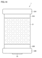
- FIG. 6 is a diagram showing the entire cylindrical filter (filter cartridge) according to an embodiment of the present disclosure.
- FIG. 7 is a diagram showing the configuration of the cylindrical filter shown in FIG. 6.
- FIG. 8 is an exploded view of the filter body.
- FIG. 9 is a partial assembly diagram showing the assembly of the upper part of the cylindrical filter (filter cartridge) according to the embodiment of the present disclosure.
- FIG. 10 is a partial assembly diagram showing the assembly of the lower part of the cylindrical filter (filter cartridge) according to the embodiment of the present disclosure.
- FIG. 11 is a view of the upper lid of the cylindrical filter (filter cartridge) according to the embodiment of the present disclosure, viewed from above and from the side.
- FIG. 12 is a schematic diagram showing the connection between the rotation mechanism and the upper lid of the cylindrical filter (filter cartridge).
- FIG. 13 is a view of the lower lid of the cylindrical filter (filter cartridge) according to the embodiment of the present disclosure, viewed from below and from the side.
- FIG. 14 is a diagram showing another form of the cylindrical filter (filter cartridge) according to the embodiment of the present disclosure.
- FIG. 15 is a block diagram schematically showing an example of a water treatment system including a filtration device according to an embodiment of the present disclosure
- the filter In the case of a filter made of non-woven fabric, depending on the quality of the water, the filter can become clogged in a short period of time due to suspended matter in the water.
- the causes of clogging include surface deposition and internal blockage.
- Surface deposition is a phenomenon in which particles larger than the average pore diameter of the filter are deposited on the surface of the filter, forming a layer of cake called a cake.
- Internal clogging is a phenomenon in which particles smaller than the average pore diameter of the filter stay inside the filter and block the flow path.
- the cake layer can be removed by washing the surface of the filter with a stream of water.
- the surface of the filter has minute irregularities, solid matter may remain in the minute depressions when the surface of the filter is cleaned. Therefore, in order to maintain the filtration performance of the filtration device, it is necessary to further increase the effectiveness of cleaning the surface of the filter with water flow.
- An object of the present disclosure is to provide a filtration device that can continue filtration processing while suppressing clogging of the filter, a filtration method using the filtration device, and a water treatment system.
- a filtration device includes a cylindrical filter having a cylindrical screen filter made of a woven fabric or a nonwoven fabric, and a water nozzle to be treated that includes a nozzle opening for flowing the water to be treated onto the surface of the screen filter. , a case having a nozzle opening inside and accommodating a cylindrical filter, and an inlet provided inside the case, and having filtered water obtained by passing the water to be treated through the screen filter.
- This is a filtration device in which the distance between the center axis and the cylindrical filter is smaller than the radius of the cylindrical filter.
- the cylindrical filter is formed of a screen filter that is a woven fabric or a nonwoven fabric with a thickness of, for example, 200 ⁇ m or less. Because the screen filter has a small film thickness, internal blockages are less likely to occur. Therefore, the main cause of clogging of the screen filter is surface deposition.
- the nozzle opening is oriented toward the surface of the screen filter so that the distance between the center line of the nozzle opening along the outflow direction of the water to be treated and the central axis of the cylindrical filter is smaller than the radius of the cylindrical filter. It will be done.
- the solid matter (cake layer) deposited on the screen filter can be removed by the water pressure of the water to be treated flowing out from the nozzle port. Furthermore, minute depressions existing near the surface of the screen filter can also be cleaned by the jet of water to be treated. Therefore, the filtration process can be continued while suppressing clogging of the filter.
- the "woven fabric” is a fabric formed by, for example, weaving resin fibers or metal wires, and the material thereof is not particularly limited.
- the angle formed by the center line of the nozzle orifice with the tangential plane of the cylindrical filter at the intersection of the center line of the nozzle orifice and the surface of the cylindrical filter is 1° or more and 45° or less. be.
- the water to be treated is obliquely incident on the tangential plane of the cylindrical filter. This makes it possible to increase the pressure of the water to be treated against the surface of the screen filter, which not only removes the solids deposited on the screen filter, but also cleans the minute depressions that exist near the surface of the screen filter. can.
- the angle is 5° or more and 15° or less. According to the above, the effect of cleaning the surface of the screen filter with the water to be treated can be enhanced.
- the cylindrical filter has a cylindrical shape having a surface in contact with the inner peripheral surface of the screen filter and a plurality of holes formed on the surface.
- the first fixing member includes a second sealing member that seals a gap between the second fixing member and the screen filter
- the rotation mechanism includes a connecting portion having a protrusion
- the first fixing member includes a second sealing member that seals a gap between the second fixing member and the screen filter.
- the second fixing member has a recess configured to receive the protrusion of the connecting portion, and a through hole for passing the filtrate flow path is formed in the second fixing member.
- the screen filter is supported by the filter support.
- the filter support is fixed by the strut, the first fixing member and the second fixing member.
- the first sealing member and the second sealing member can seal between the screen filter and the filter support.
- the screen filter is supported in a cylindrical shape.
- the recessed portion of the first fixing member is formed to receive the protrusion of the connecting portion of the rotating mechanism, the first fixing member and the rotating mechanism can be coupled.
- the water to be treated can be filtered by the screen filter while rotating the cylindrical filter. Since the filtered water to be treated passes through the holes formed in the filter support, it can be taken out from the filtrate flow path.
- a water treatment system includes the filtration device according to any one of (1) to (4) above.
- a filtration method is a filtration method in which water to be treated is filtered by a cylindrical filter having a cylindrical screen filter made of a woven fabric or a nonwoven fabric, the step of rotating the cylindrical filter; and a step of flowing out the water to be treated from the nozzle opening of the water nozzle so that the water to be treated passes through the screen filter.
- the method includes the step of causing the water to be treated to flow out in a direction in which the distance between the center line of the mouth and the center axis of the cylindrical filter is smaller than the radius of the cylindrical filter.
- FIG. 1 is a schematic diagram schematically showing a filtration method according to an embodiment of the present disclosure.
- FIG. 2 is a diagram for explaining the mechanism of filtering water to be treated by the filtration method according to the embodiment of the present disclosure.
- the filtration method according to the embodiment of the present disclosure generates filtered water 6 by filtering water to be treated 5 using a cylindrical filter 1.
- the cylindrical filter 1 is housed in a case 10.
- the cylindrical filter 1 is a cylindrical screen filter.
- a woven fabric or a nonwoven fabric having a thickness of, for example, 200 ⁇ m or less is used as the screen filter.
- the type of thread used in the woven fabric is not particularly limited, and may be metal (for example, SUS) wire or resin fiber.
- a nonwoven fabric is a sheet of fibers that are intertwined without being woven.
- nonwoven fabric for example, JIS L0222 can be used.
- the type of resin fiber used for the nonwoven fabric is not particularly limited.
- the separation target 3 is removed from the water to be treated 5, and filtered water is obtained.
- the separation target 3 adheres to the surface of the cylindrical filter 1 .
- the cylindrical filter 1 rotates around the central axis 2 of the cylinder
- the water to be treated 5 is flowed toward the surface of the cylindrical filter 1 (cylinder).
- the object to be separated 3 can be removed from the surface of the cylindrical filter 1 by the flow of the water to be treated 5 directed toward the surface of the cylindrical filter 1 (cylinder). Therefore, formation of a cake layer on the surface of the cylindrical filter 1 can be prevented. Note that, as shown in FIGS. 1 and 2, the direction of rotation of the cylindrical filter 1 and the direction of flow of the water to be treated 5 are the same.
- FIG. 3 is a schematic diagram for explaining cleaning of a filter by filtration processing according to an embodiment of the present disclosure.
- the water to be treated 5 is ejected from the water to be treated nozzle 11.
- the water nozzle 11 to be treated has a nozzle port 12 (opening) facing the cylindrical filter 1 (screen filter).
- the center line 12A represents the center line of the nozzle port 12 along the outflow direction of the water to be treated 5.
- the center line 12A intersects the surface of the cylindrical filter 1 (screen filter) at point A.
- the tangential plane 4 is a virtual plane that touches the surface of the cylindrical filter 1 (screen filter) at point A.
- the radius of curvature of the cylindrical filter 1 (screen filter) is expressed as R.
- the radius of curvature R is equal to the distance from the central axis 2 of the cylindrical filter 1 to the tangential plane 4. That is, the length of the perpendicular from the central axis 2 of the cylinder to the tangential plane 4 is R. This perpendicular intersects the tangent plane 4 at point A. Further, the distance between the center line 12A of the nozzle opening 12 and the center axis 2 of the cylindrical filter 1 is expressed as D.
- the distance D is smaller than the radius of curvature R of the cylindrical filter 1. That is, D ⁇ R.
- solid matter (cake layer) deposited on the screen filter is removed by the water pressure of the water to be treated 5 flowing out from the nozzle port 12. can be removed.
- minute depressions existing near the surface of the screen filter can also be cleaned by the jet stream of the water to be treated 5. Therefore, the filtration process can be continued while suppressing clogging of the filter.
- the angle ⁇ is an angle greater than 0°.
- the angle ⁇ is 1° or more and 45° or less.
- the angle ⁇ is 1° or more, in addition to the effect of removing solid matter (cake layer) by the jet stream of the water to be treated 5, it is also possible to obtain the effect of cleaning minute depressions existing near the surface of the screen filter. can.
- the angle ⁇ is increased, the rotation of the cylindrical filter 1 may be hindered by the jet of the water to be treated 5 .
- angle ⁇ By setting the angle ⁇ to 45° or less, it is possible to filter the water to be treated 5 and wash the surface of the screen filter while avoiding the jet of the water to be treated 5 from interfering with the rotation of the cylindrical filter 1. can.
- the effect of cleaning the screen filter surface when the angle ⁇ is changed will be explained in detail later.
- FIG. 4 is a schematic cross-sectional view showing an outline of the configuration of a filtration device according to an embodiment of the present disclosure.
- the filtration device 101 according to the embodiment of the present disclosure includes a cylindrical filter 1, a case 10, a water nozzle 11, a drainage channel 13, and filtrate channels 15A and 15B. , a motor 16, a motor cover 17, a connecting portion 18, and a bearing portion 19.
- the case 10 has a nozzle opening 12 of the water nozzle 11 to be treated, an outlet 14 of the drainage channel 13, and filtrated water channels 15A and 15B inside thereof, and also houses the cylindrical filter 1 and the motor 16.
- the case 10 may be integrally formed with the water to be treated nozzle 11, the drainage channel 13, and the filtrate channels 15A and 15B.
- the cylindrical filter 1 is a cylindrical filter that includes a woven fabric or a nonwoven fabric with a film thickness of, for example, 200 ⁇ m or less as a screen filter.
- the water to be treated nozzle 11 includes a nozzle opening 12 through which the water to be treated flows out toward the surface of the cylindrical filter.
- the height of the nozzle opening 12 is not particularly limited. In one embodiment, the height of the nozzle orifice 12 may be smaller than the height of the cylindrical filter 1.
- the filtered water channels 15A and 15B are channels for leading the water to be treated (filtered water) filtered by the cylindrical filter 1 from the inside of the case 10 to the outside of the case 10.
- the filtered water flow path 15A passes through the inside of the cylindrical filter 1. For this reason, a through hole is formed at the lower end of the cylindrical filter 1 to allow the filtrate flow path 15A to pass therethrough.
- the filtrate water channels 15A and 15B communicate with each other.
- the filtered water that has passed through the cylindrical filter 1 is taken into the inlet of the filtered water flow path 15A, flows through the filtered water flow path 15A, and is taken out from the filtered water flow path 15B.
- the drainage channel 13 is a channel for discharging the wastewater containing the separation target substances removed by the cylindrical filter 1 to the outside of the case 10.
- the drainage channel 13 may be provided with a valve. By controlling the opening and closing of the valve, the throughput of the filtration device can be controlled.
- the valve when the water to be treated is being filtered by the cylindrical filter 1, the valve may be closed.
- the filtration device 101 can filter the water to be treated while cleaning the cylindrical filter 1. Thereby, the entire amount of water to be treated 5 supplied to the filtration device 101 can be filtered by the filtration device 101, so that the production capacity of filtered water can be increased.
- the valve is opened. Thereby, the separation target accumulated inside the case 10 during the filtration process can be discharged to the outside of the filtration device 101 through the drainage channel 13.
- the valve may be in an open state when filtering the water to be treated. In this case, part of the inflowing water to be treated can be filtered while being drained.
- the motor 16 rotates the cylindrical filter 1 around the central axis 2 of the cylinder. In order to obtain the desired torque for rotating the cylindrical filter 1, the motor 16 may be combined with a speed reducer.
- Motor cover 17 is attached to case 10 and covers motor 16 (and reduction gear).
- the rotating shaft of the motor 16 (if the motor 16 is coupled to a reducer, the rotating shaft of the reducer) is coupled to the connecting portion 18 .
- the cylindrical filter 1 is connected to a motor 16 (or a speed reducer) via a connecting portion 18.
- the motor 16 (or the combination of the motor 16 and the speed reducer) and the connecting portion 18 correspond to a rotation mechanism for rotating the cylindrical filter 1.
- a bearing portion 19 for supporting the rotating cylindrical filter 1 is provided on the lower end side of the cylindrical filter 1 .
- FIG. 5 is a diagram illustrating the effects of the filtration method according to an embodiment of the present disclosure.
- the horizontal axis shows the time of the filtration process by the filtration method according to the embodiment of the present disclosure
- the vertical axis shows the pressure drop p (unit: kPa) of the cylindrical filter.
- the graph in FIG. 5 shows the degree of increase in pressure drop with respect to the time of the filtration process when an experiment was performed by changing the angle between the center line of the nozzle opening 12 and the filter tangent plane (see FIG. 3). Note that the flow rate of the water to be treated to be supplied to the filter was the same regardless of the angle.
- the degree of increase in pressure drop becomes smaller. Comparing the degree of increase in pressure drop when the filtration treatment time is from 0 minutes to 90 minutes, the pressure loss when the angle between the center line of the nozzle port 12 and the tangential plane is 0 degrees to 45 degrees is 90 minutes. It is smaller than the pressure loss when the temperature is high, and is suppressed to approximately 1/2 or less.
- the angle between the center line of the nozzle opening 12 and the filter tangent plane is 5 degrees, the degree of increase in pressure loss is smaller than when the angle is 0 degrees, 15 degrees, 30 degrees, or 45 degrees. This is considered to be because the depressions on the filter surface were cleaned more effectively. It was also confirmed that as the filtration time increases, the degree of increase in pressure loss when the angle is 15 degrees becomes smaller than the degree of increase in pressure loss when the angle is 30 degrees and 45 degrees. This is thought to be because as the angle increases, although the cake layer on the filter surface is removed by the water to be treated, the effect of cleaning the depressions on the filter surface becomes weaker. Therefore, the angle between the center line of the nozzle orifice 12 and the tangential plane is preferably greater than 0 degrees (for example, 1 degree) to 45 degrees, and more preferably between 5 degrees and 15 degrees.
- the cylindrical filter 1 can be a cartridge-type filter. This makes it possible to realize a replaceable filter.
- FIG. 6 is a diagram showing the entire cylindrical filter (filter cartridge) according to an embodiment of the present disclosure.
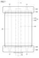
- FIG. 7 is a diagram showing the configuration of the cylindrical filter shown in FIG. 6.
- the cylindrical filter 1 includes a filter main body 21, lids 22A and 22B, seal tapes 23A and 23B, sealing members 24A and 24B, a bearing ring 25, and a strut 26. and a screw 27. Note that for convenience of illustration, the strut 26 and the screw 27 are not shown in FIG. 6, and the seal tapes 23A and 23B are not shown in FIG.
- the filter body 21 includes a screen filter 21A and a cylindrical filter support 21B.
- the support column 26 is arranged inside the filter support body 21B so as to extend along the direction of the central axis 2 of the cylindrical filter 1.
- the lid 22A is arranged at the first end (upper end) of the filter support 21B and closes the opening at the first end.
- the lid 22B is arranged at the second end (lower end) of the filter support 21B opposite to the first end, and closes the opening at that end.
- the end of the support column 26 on the upper end side of the filter support 21B is fixed to the lid 22A with a screw 27.
- the end of the column 26 on the lower end side of the filter support 21B is also fixed to the lid 22B with a screw 27.
- the strut 26 is fixed to the lids 22A, 22B, and the filter support 21B is supported by the strut 26 and the lids 22A, 22B.
- the seal tapes 23A and 23B are wound around the upper and lower ends of the cylindrical screen filter 21A, respectively.
- the seal tapes 23A and 23B fix the screen filter 21A to the filter support 21B and fill the gap between the screen filter 21A and the filter support 21B.
- the sealing member 24A is provided at the upper end of the filter support 21B so as to surround the seal tape 23A and the lid 22A.
- the sealing member 24B is provided at the lower end of the filter support 21B so as to surround the seal tape 23B and the lid 22B.
- the sealing members 24A and 24B seal the gap between the screen filter 21A and the filter support body 21B together with the seal tapes 23A and 23B. Therefore, in this embodiment, the sealing member 24A and the sealing tape 23A are connected to the first sealing member that seals the gap between the lid body 22A and the screen filter 21A on the upper end side of the filter support body 21B. Equivalent to.
- the sealing member 24B and the sealing tape 23B correspond to a second sealing member that seals the gap between the lid body 22B and the screen filter 21A on the lower end side of the filter support body 21B.
- a through hole is formed in the lid 22B in order to pass the filtered water flow path 15A into the filter support 21B.
- the bearing ring 25 is inserted into the through hole of the lid 22B.
- a lid 22A is placed over the upper end of the filtrate water channel 15A.
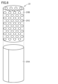
- FIG. 8 is an exploded view of the filter body 21.
- the filter support 21B has a cylindrical shape.
- the filter support body 21B has a surface in which a plurality of holes 21C are formed.
- the filter support 21B is formed by processing a metal sheet with holes (generally referred to as "punching metal") into a cylindrical shape.
- the screen filter 21A is wound so that the surface of the filter support 21B is in contact with the inner peripheral surface of the screen filter 21A. Therefore, a cylindrical screen filter is formed.
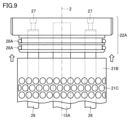
- FIG. 9 is a partial assembly diagram showing the assembly of the upper part of the cylindrical filter (filter cartridge) according to the embodiment of the present disclosure.
- illustration of the seal tape 23A and the sealing member 24A shown in FIG. 6 is omitted.
- the upper end of the support column 26 is inserted into the lid 22A and fixed to the lid 22A with screws 27.
- the filter support 21B is passed through the filtrate water channel 15A, and the lid 22A is placed over the filtrate water channel 15A.
- the lid 22A is attached to the upper end of the filter support 21B.
- An O-ring 28A is attached to the lid 22A to fill the gap between the lid 22A and the filter support 21B.
- FIG. 10 is a partial assembly diagram showing the assembly of the lower part of the cylindrical filter (filter cartridge) according to the embodiment of the present disclosure.
- illustration of the seal tape 23B and the sealing member 24B shown in FIG. 6 is omitted.
- the lower end of the column 26 is inserted into the lid 22B and fixed to the lid 22B with screws 27.
- the bearing ring 25 is inserted into the through hole of the lid body 22B.
- the filtrate water channel 15A is passed through the hollow part of the bearing ring 25, and the lid body 22B is attached to the lower end of the filter support body 21B.
- An O-ring 28B is attached to the lid 22B to fill the gap between the lid 22B and the filter support 21B.
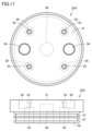
- FIG. 11 is a view of the upper lid of the cylindrical filter (filter cartridge) according to the embodiment of the present disclosure, viewed from above and from the side.
- the lid body 22A has a top surface 31 and a bottom surface 32.
- a plurality of screw holes 33 and a recess 34 are formed in the top surface 31 of the lid body 22A for passing screws for fixing the support column.
- a plurality of holes 35 for receiving the pillars and a hole 36 for receiving the filtrate flow path 15A are formed in the lower surface 32 on the opposite side from the top surface 31.
- the recess 34 does not reach the lower surface 32 of the lid 22A.
- the hole 36 formed in the lower surface 32 does not reach the top surface 31.
- the hole 36 is formed at the center of the lower surface 32 of the lid 22A.
- the two recesses 34 are arranged symmetrically with respect to the hole 36.
- the four holes 35 and the four screw holes 33 are arranged symmetrically with respect to the hole 36.
- the lid 22A closes the end (upper end) of the filter support 21B by being inserted into the opening at the end (upper end) of the filter support 21B.
- a groove 37 is formed in the portion of the lid 22A that is inserted into the end (upper end) of the filter support 21B.
- An O-ring 28A may be fitted into the groove 37 in order to improve the sealing performance of the upper end of the filter support 21B (see FIG. 9).
- FIG. 12 is a schematic diagram showing the connection between the rotation mechanism and the upper lid of the cylindrical filter (filter cartridge).
- the connecting portion 18 has a protrusion 18A.
- the recess 34 of the lid 22A is formed on the top surface of the lid 22A to receive the protrusion 18A. Thereby, the lid body 22A and the connecting portion 18 are coupled together.
- FIG. 13 is a view of the lower lid of the cylindrical filter (filter cartridge) according to the embodiment of the present disclosure, viewed from below and from the side.
- the lid body 22B has a top surface 41 and a bottom surface 42.
- a plurality of screw holes 43 are formed in the top surface 41 of the lid body 22B for passing screws 27 for fixing the support columns 26.
- a plurality of holes 45 for receiving the pillars 26 are formed in the lower surface 42 on the opposite side from the top surface 41 .
- Each of the plurality of screw holes 43 and the hole 45 corresponding to the screw hole 43 are connected.
- the lid 22B closes the end (lower end) of the filter support 21B by being inserted into the opening at the end (lower end) of the filter support 21B.
- a groove 47 is formed in the portion of the lid 22B that is inserted into the end (lower end) of the filter support 21B.
- An O-ring 28B may be fitted in the groove 47 to improve the sealing performance of the upper end of the filter support 21B (see FIG. 10).
- a through hole 46 communicating from the top surface 41 to the bottom surface 42 is formed in the center portion of the lid body 22B.
- the through hole 46 is a hole through which the filtrate flow path 15A (see FIG. 4) passes. Note that the bearing ring 25 is inserted into the through hole 46.
- the four holes 45 and the four screw holes 43 are arranged symmetrically with respect to the through hole 46.
- FIG. 14 is a diagram showing another form of the cylindrical filter (filter cartridge) according to the embodiment of the present disclosure.
- the sealing members 24A and 24B are omitted from the cylindrical filter (filter cartridge) 1.
- the gap between the screen filter 21A and the filter support 21B may be sealed only with seal tapes 23A and 23B.
- a filtration device that is useful for water treatment systems that require filtration of water to be treated as a pretreatment.
- a filtration device according to an embodiment of the present disclosure can be applied to a water treatment system.
- the type of water treatment system equipped with the filtration device according to the embodiment of the present disclosure is not particularly limited, one specific example will be described below.
- FIG. 15 is a block diagram schematically showing an example of a water treatment system including a filtration device according to an embodiment of the present disclosure.
- the water treatment system according to the embodiment of the present disclosure can be realized, for example, as a seawater desalination system 201.
- the seawater desalination system 201 includes the above-described filtration device 101, a filtration device 102 including a filter 112 formed from an ultrafiltration membrane (UF membrane) or a microfiltration membrane (MF membrane), and a reverse osmosis membrane (RO membrane). and a reverse osmosis membrane permeation device 103 including a filter 113 formed from.
- the pore diameter of the filter 112 is smaller than the pore diameter of the cylindrical filter 1 of the filtration device 101.
- the filtration device 101 In the seawater desalination system 201, the filtration device 101 according to the embodiment of the present disclosure is used as a pre-filter, and filters the water to be treated 5, which is seawater.
- the filtered water 6 is further filtered by a filtering device 102.
- Filtered water 7 from filtration device 102 is supplied to reverse osmosis membrane permeation device 103 .
- Pure water 8 is generated by passing filtered water 7 through filter 113 of reverse osmosis membrane permeation device 103 .
- Pure water 8 is stored in a tank 104.
Landscapes
- Chemical & Material Sciences (AREA)
- Chemical Kinetics & Catalysis (AREA)
- Life Sciences & Earth Sciences (AREA)
- Hydrology & Water Resources (AREA)
- Engineering & Computer Science (AREA)
- Environmental & Geological Engineering (AREA)
- Water Supply & Treatment (AREA)
- Organic Chemistry (AREA)
- Filtration Of Liquid (AREA)
Priority Applications (4)
| Application Number | Priority Date | Filing Date | Title |
|---|---|---|---|
| US18/844,637 US20250222378A1 (en) | 2022-03-18 | 2023-03-16 | Filtering apparatus, filtering method, and water treatment system |
| CN202380025808.2A CN118871178A (zh) | 2022-03-18 | 2023-03-16 | 过滤装置、过滤方法以及水处理系统 |
| KR1020247030345A KR20240160115A (ko) | 2022-03-18 | 2023-03-16 | 여과 장치, 여과 방법 및 수처리 시스템 |
| JP2024508257A JPWO2023176933A1 (https=) | 2022-03-18 | 2023-03-16 |
Applications Claiming Priority (2)
| Application Number | Priority Date | Filing Date | Title |
|---|---|---|---|
| JP2022043274 | 2022-03-18 | ||
| JP2022-043274 | 2022-03-18 |
Publications (1)
| Publication Number | Publication Date |
|---|---|
| WO2023176933A1 true WO2023176933A1 (ja) | 2023-09-21 |
Family
ID=88023332
Family Applications (1)
| Application Number | Title | Priority Date | Filing Date |
|---|---|---|---|
| PCT/JP2023/010368 Ceased WO2023176933A1 (ja) | 2022-03-18 | 2023-03-16 | 濾過装置、濾過方法および水処理システム |
Country Status (5)
| Country | Link |
|---|---|
| US (1) | US20250222378A1 (https=) |
| JP (1) | JPWO2023176933A1 (https=) |
| KR (1) | KR20240160115A (https=) |
| CN (1) | CN118871178A (https=) |
| WO (1) | WO2023176933A1 (https=) |
Citations (6)
| Publication number | Priority date | Publication date | Assignee | Title |
|---|---|---|---|---|
| JPS61200825A (ja) * | 1985-03-01 | 1986-09-05 | Arai Tekkosho:Kk | 濾過装置 |
| JPS61167912U (https=) * | 1985-04-01 | 1986-10-18 | ||
| JPS61187210U (https=) * | 1985-05-15 | 1986-11-21 | ||
| JP2004313837A (ja) * | 2003-04-11 | 2004-11-11 | Kiyonekkusu Kk | フィルタケース |
| JP2011194396A (ja) * | 2010-02-25 | 2011-10-06 | Sumitomo Electric Ind Ltd | 船舶用バラスト水の処理装置 |
| WO2016093010A1 (ja) * | 2014-12-09 | 2016-06-16 | 住友電気工業株式会社 | 洗浄モジュール及び複層濾過塔 |
Family Cites Families (1)
| Publication number | Priority date | Publication date | Assignee | Title |
|---|---|---|---|---|
| JP2015009170A (ja) | 2013-06-27 | 2015-01-19 | 住友電気工業株式会社 | プリーツフィルター、それを用いたバラスト水処理装置およびバラスト水の処理方法 |
-
2023
- 2023-03-16 JP JP2024508257A patent/JPWO2023176933A1/ja active Pending
- 2023-03-16 WO PCT/JP2023/010368 patent/WO2023176933A1/ja not_active Ceased
- 2023-03-16 US US18/844,637 patent/US20250222378A1/en active Pending
- 2023-03-16 CN CN202380025808.2A patent/CN118871178A/zh active Pending
- 2023-03-16 KR KR1020247030345A patent/KR20240160115A/ko active Pending
Patent Citations (6)
| Publication number | Priority date | Publication date | Assignee | Title |
|---|---|---|---|---|
| JPS61200825A (ja) * | 1985-03-01 | 1986-09-05 | Arai Tekkosho:Kk | 濾過装置 |
| JPS61167912U (https=) * | 1985-04-01 | 1986-10-18 | ||
| JPS61187210U (https=) * | 1985-05-15 | 1986-11-21 | ||
| JP2004313837A (ja) * | 2003-04-11 | 2004-11-11 | Kiyonekkusu Kk | フィルタケース |
| JP2011194396A (ja) * | 2010-02-25 | 2011-10-06 | Sumitomo Electric Ind Ltd | 船舶用バラスト水の処理装置 |
| WO2016093010A1 (ja) * | 2014-12-09 | 2016-06-16 | 住友電気工業株式会社 | 洗浄モジュール及び複層濾過塔 |
Also Published As
| Publication number | Publication date |
|---|---|
| CN118871178A (zh) | 2024-10-29 |
| KR20240160115A (ko) | 2024-11-08 |
| JPWO2023176933A1 (https=) | 2023-09-21 |
| US20250222378A1 (en) | 2025-07-10 |
Similar Documents
| Publication | Publication Date | Title |
|---|---|---|
| US4414113A (en) | Liquid purification using reverse osmosis hollow fibers | |
| JP3299969B2 (ja) | 純水を製造するための方法及び浄水装置 | |
| US4411785A (en) | Reverse osmosis hollow fiber filter element | |
| KR20100051068A (ko) | 디스크 필터용 배기 장치 | |
| KR20100051067A (ko) | 디스크 필터용 폐물 관용 필터 지지대 | |
| CZ20012794A3 (cs) | Postup filtrace kříľovým tokem | |
| JP7426478B2 (ja) | 選択型両端集水機能を有するフィルタ構造体およびこれを利用した濾過方法 | |
| WO2017133641A1 (zh) | 膜元件 | |
| JP6608631B2 (ja) | 濾過装置及び濾過装置のフィルター洗浄方法 | |
| JP2012115747A (ja) | 中空糸膜モジュールおよび中空糸膜モジュール濾過装置 | |
| WO2023176933A1 (ja) | 濾過装置、濾過方法および水処理システム | |
| KR20000054043A (ko) | 드럼필터를 이용한 여과방법 | |
| FI106614B (fi) | Menetelmä ja laitteisto hienojakoista kiintoainesta sisältävän nestevirtauksen kirkastamiseksi | |
| JPH07241413A (ja) | 回転ドラム型固液分離装置 | |
| CN115382397B (zh) | 中空纤维膜组件以及使用方法 | |
| JP3489383B2 (ja) | 中空糸膜モジュール及び濾過器 | |
| JP6693775B2 (ja) | 濾過装置、濾過方法および水処理システム | |
| CN218280758U (zh) | 过滤筒 | |
| RU2237509C1 (ru) | Фильтр для очистки жидкостей | |
| KR102511322B1 (ko) | 고농도 유입수 전처리용 부상식 부위형 자동역세 여과 장치 | |
| JP2691846B2 (ja) | 固液分離方法及びその装置 | |
| JP4744519B2 (ja) | 濾過方法およびシステム | |
| JPH067774A (ja) | 浄水器 | |
| JPS61238391A (ja) | 濾過器 | |
| JP2570029Y2 (ja) | 浄水用カートリッジ |
Legal Events
| Date | Code | Title | Description |
|---|---|---|---|
| 121 | Ep: the epo has been informed by wipo that ep was designated in this application |
Ref document number: 23770886 Country of ref document: EP Kind code of ref document: A1 |
|
| WWE | Wipo information: entry into national phase |
Ref document number: 202380025808.2 Country of ref document: CN |
|
| WWE | Wipo information: entry into national phase |
Ref document number: 18844637 Country of ref document: US |
|
| ENP | Entry into the national phase |
Ref document number: 20247030345 Country of ref document: KR Kind code of ref document: A |
|
| ENP | Entry into the national phase |
Ref document number: 2024508257 Country of ref document: JP Kind code of ref document: A |
|
| NENP | Non-entry into the national phase |
Ref country code: DE |
|
| 122 | Ep: pct application non-entry in european phase |
Ref document number: 23770886 Country of ref document: EP Kind code of ref document: A1 |
|
| WWP | Wipo information: published in national office |
Ref document number: 18844637 Country of ref document: US |