WO2023176619A1 - 切削インサート、切削工具、及び切削加工物の製造方法 - Google Patents
切削インサート、切削工具、及び切削加工物の製造方法 Download PDFInfo
- Publication number
- WO2023176619A1 WO2023176619A1 PCT/JP2023/008796 JP2023008796W WO2023176619A1 WO 2023176619 A1 WO2023176619 A1 WO 2023176619A1 JP 2023008796 W JP2023008796 W JP 2023008796W WO 2023176619 A1 WO2023176619 A1 WO 2023176619A1
- Authority
- WO
- WIPO (PCT)
- Prior art keywords
- inclined surface
- region
- corner
- cutting
- increases
- Prior art date
- Legal status (The legal status is an assumption and is not a legal conclusion. Google has not performed a legal analysis and makes no representation as to the accuracy of the status listed.)
- Ceased
Links
Images


Classifications
-
- B—PERFORMING OPERATIONS; TRANSPORTING
- B23—MACHINE TOOLS; METAL-WORKING NOT OTHERWISE PROVIDED FOR
- B23C—MILLING
- B23C5/00—Milling-cutters
- B23C5/16—Milling-cutters characterised by physical features other than shape
- B23C5/20—Milling-cutters characterised by physical features other than shape with removable cutter bits or teeth or cutting inserts
- B23C5/202—Plate-like cutting inserts with special form
-
- B—PERFORMING OPERATIONS; TRANSPORTING
- B23—MACHINE TOOLS; METAL-WORKING NOT OTHERWISE PROVIDED FOR
- B23C—MILLING
- B23C5/00—Milling-cutters
- B23C5/02—Milling-cutters characterised by the shape of the cutter
- B23C5/06—Face-milling cutters, i.e. having only or primarily a substantially flat cutting surface
-
- B—PERFORMING OPERATIONS; TRANSPORTING
- B23—MACHINE TOOLS; METAL-WORKING NOT OTHERWISE PROVIDED FOR
- B23C—MILLING
- B23C2200/00—Details of milling cutting inserts
- B23C2200/04—Overall shape
- B23C2200/0422—Octagonal
-
- B—PERFORMING OPERATIONS; TRANSPORTING
- B23—MACHINE TOOLS; METAL-WORKING NOT OTHERWISE PROVIDED FOR
- B23C—MILLING
- B23C2200/00—Details of milling cutting inserts
- B23C2200/08—Rake or top surfaces
- B23C2200/083—Rake or top surfaces curved
Definitions
- the present disclosure relates to a cutting insert, a cutting tool, and a method for manufacturing a cut workpiece.
- a cutting insert described in Patent Document 1 is known as a cutting insert used in a cutting tool.
- the cutting insert described in Patent Document 1 has a main cutting edge and a rake face extending from the main cutting edge.
- the rake face includes a linear portion (referred to as a land portion (6c) in Patent Document 1) and a convex curved portion protruding upward (referred to as the main rake surface (in Patent Document 1)). 6a)).
- the linear portion is located along the main cutting edge, and the convex curved portion is located inside the linear portion.
- the cutting insert according to the present disclosure has an upper surface, a lower surface located on the opposite side of the upper surface, a side surface connected to the upper surface and the lower surface, and a cutting edge located at the intersection of the upper surface and the side surface.
- the upper surface includes a corner portion, a side portion that is connected to the corner portion and approaches the bottom surface as it moves away from the corner portion, an outer inclined surface that extends along the side portion and approaches the lower surface as it moves away from the edge portion, and an outer slope.
- a medium slope extending along the surface and approaching the lower surface as it moves away from the medium slope, an internal slope extending along the medium slope and approaching the bottom surface as it moves away from the medium slope, and a medium slope connected to the medium slope. and a flat bottom surface.
- the outer inclined surface In a cross section taken in a direction parallel to the center axis of the insert passing through the center of the upper surface and the center of the lower surface, the outer inclined surface has a linear shape, and the middle inclined surface has a convex curved shape that projects upward. .
- the side portion has a first portion connected to the corner portion and a second portion connected to the first portion.
- the outer inclined surface extends along the first portion and includes a first outer region whose width in a direction perpendicular to the first portion becomes narrower as the distance from the corner portion increases; Therefore, it has a second outer region that is wider in the direction perpendicular to the second portion.
- the intermediate inclined surface extends along the first outer region, and the width in the direction perpendicular to the first portion increases as the distance from the corner increases, and the second outer region extends from the corner. and a second intermediate region whose width in the direction perpendicular to the second region becomes narrower as the distance from the second region increases.
- the cutting tool according to the present disclosure has a cylindrical shape extending from a first end to a second end along a rotation axis, and includes a holder having a pocket located on the first end side, and a main body located in the pocket.
- a cutting insert according to the disclosure is a cylindrical shape extending from a first end to a second end along a rotation axis, and includes a holder having a pocket located on the first end side, and a main body located in the pocket.
- a method for manufacturing a cut workpiece according to the present disclosure includes a step of rotating a cutting tool according to the present disclosure, a step of bringing the rotating cutting tool into contact with a workpiece, and a step of separating the cutting tool from the workpiece. Be prepared.
- FIG. 1 is a schematic perspective view of a cutting insert according to an embodiment of the present disclosure.
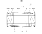
- FIG. 2 is a schematic plan view of the cutting insert shown in FIG. 1.
- FIG. 2 is a schematic side view of the cutting insert shown in FIG. 1.
- FIG. 3 is an enlarged view of section IV in FIG. 2.
- FIG. 5 is an enlarged sectional view taken along the line VV in FIG. 4.
- FIG. 5 is an enlarged cross-sectional view taken along line VI-VI in FIG. 4.
- FIG. 5 is an enlarged cross-sectional view taken along the line VII-VII in FIG. 4.
- FIG. 5 is an enlarged sectional view taken along line VIII-VIII in FIG. 4.
- FIG. 5 is an enlarged cross-sectional view along IX-IX in FIG. 4.
- FIG. 4 is a schematic perspective view of a cutting insert according to an embodiment of the present disclosure.
- FIG. 2 is a schematic plan view of the cutting insert shown in FIG. 1.
- FIG. 3 is an enlarged view
- FIG. 3 is an enlarged sectional view taken along line XX in FIG. 2.
- FIG. FIG. 1 is a schematic perspective view of a cutting tool according to an embodiment of the present disclosure.
- FIG. 12 is a schematic perspective view of the cutting tool shown in FIG. 11 viewed from another angle.
- FIG. 2 is a schematic diagram illustrating a method for manufacturing a cut workpiece according to an embodiment of the present disclosure.
- FIG. 2 is a schematic diagram illustrating a method for manufacturing a cut workpiece according to an embodiment of the present disclosure.
- FIG. 2 is a schematic diagram illustrating a method for manufacturing a cut workpiece according to an embodiment of the present disclosure.
- the linear portion of the rake face in the cutting insert described in Patent Document 1 extends monotonically along the entire main cutting edge. Therefore, when performing cutting with a large depth of cut, there is a risk that the linear portion of the rake face may come into excessive contact with chips. Therefore, it is desired to improve the chip discharge performance and the durability of the rake face.
- the insert center axis refers to a virtual axis passing through the center of the upper surface of the cutting insert and the center of the lower surface of the cutting insert.
- the term “inward direction” or “inner side” refers to a direction toward or toward the insert central axis in the cutting insert.
- the term “outward direction” or “outside” refers to a direction away from or a side away from the center axis of the cutting insert in the cutting insert.
- Orthogonality is not limited to exact orthogonality, but means to allow an error of approximately ⁇ 5 degrees.
- Parallel is not limited to exact parallel, but means to allow an error of about ⁇ 5 degrees.
- FIG. 1 is a schematic perspective view of a cutting insert 10 according to an embodiment of the present disclosure.
- FIG. 2 is a schematic plan view of the cutting insert 10 shown in FIG. 1.
- FIG. 3 is a schematic side view of the cutting insert 10 shown in FIG. 1. Note that FIG. 3 is a side view of the first side, which will be described later, viewed from the front.
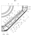
- FIG. 4 is an enlarged view of section IV in FIG. 2.
- FIG. 5 is an enlarged sectional view taken along line VV in FIG. 4.
- FIG. 6 is an enlarged cross-sectional view taken along line VI-VI in FIG.
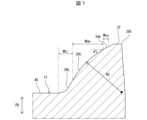
- FIG. 7 is an enlarged sectional view taken along line VII-VII in FIG. 4.
- FIG. 8 is an enlarged sectional view taken along line VIII-VIII in FIG. 4.
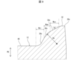
- FIG. 9 is an enlarged cross-sectional view taken along line IX-IX in FIG.
- FIG. 10 is an enlarged sectional view taken along line XX in FIG. 4.
- the cutting insert 10 of this embodiment is a part of a cutting tool used for cutting (milling) a workpiece W (see FIG. 13) made of a metal material or the like.
- Examples of the cutting process for the work material W include shoulder cutting, groove cutting, R cutting, and copying.
- the cutting insert 10 may have an upper surface 12 and a lower surface 14 located on the opposite side of the upper surface 12.
- the upper surface 12 and the lower surface 14 may each have a polygonal shape, for example an octagonal shape.
- the cutting insert 10 may have a polygonal plate shape, for example, an octagonal plate shape.
- the upper surface 12 and the lower surface 14 may each have a polygonal shape other than an octagonal shape, such as a triangular shape or a quadrangular shape.
- the cutting insert 10 may have a polygonal plate shape other than the octagonal plate shape, such as a triangular plate shape or a square plate shape.
- a polygonal shape is not limited to a polygonal shape in a strict sense.
- the upper surface 12 and the lower surface 14 may each have a rotationally symmetrical shape by a certain angle around the insert center axis CS.
- the upper surface 12 and the lower surface 14 may have a reversely symmetrical shape.
- the cutting insert 10 may have a shape that is rotationally symmetrical by a certain angle about the insert center axis CS, or may have a shape that is invertedly symmetrical between the front and back sides.
- the cutting insert 10 may have a side surface 16 located between the upper surface 12 and the lower surface 14. Side surface 16 may be connected to top surface 12 and bottom surface 14. The side surface 16 may function as a relief surface. Further, the cutting insert 10 may have a mounting hole 18 penetrating from the upper surface 12 to the lower surface 14. One opening of the attachment hole 18 may be located at the center of the upper surface 12, and the other opening of the attachment hole 18 may be located at the center of the lower surface 14. The center axis of the attachment hole 18 may coincide with the insert center axis CS.
- the cutting insert 10 may have an upper cutting edge 20 and a lower cutting edge 22.
- the upper cutting edge 20 may be located at the intersection of the upper surface 12 and the side surface 16.
- the lower cutting edge 22 may be located at the intersection of the lower surface 14 and the side surface 16.
- the cutting insert 10 may be a double-sided insert having an upper cutting edge 20 and a lower cutting edge 22.
- the upper cutting edge 20 may be located at the entire intersection of the upper surface 12 and the side surface 16, or may be located at a portion of the intersection.
- the lower cutting edge 22 may be located at the entire intersection of the lower surface 14 and the side surface 16, or may be located at a portion of the intersection.
- the polygonal top surface 12 may have a first corner 24 as a corner portion and a second corner 26 as another corner portion.
- the first corner 24 and the second corner 26 may each have a convex curved shape that projects outward in a top view.
- the upper surface 12 has a first side 28 as a side connected to the first corner 24 and a first side 28 connected to the first corner 24 on the opposite side of the first side 28. It may also have a second side 30 as another side.
- the second corner 26 may be connected to the second side 30 on the opposite side from the first corner 24 .
- the first side 28 may have a linear shape when viewed from above, or may approach the lower surface 14 as it moves away from the first corner 24 when viewed from the side.
- the second side 30 may have a linear shape when viewed from above.
- first side 28 and the second side 30 are not limited to a linear shape, but may have a gently convex curved shape that protrudes outward, for example.
- “having a gentle convex curve shape” means that the radius of curvature is larger than the radius of curvature of the first corner 24 and the second corner 26, which are convex curve shapes.
- the upper surface 12 has a shape that is rotationally symmetrical by a certain angle about the insert center axis CS
- the upper surface 12 has a plurality of first corners 24 and a plurality of second corners 26, as shown in the example shown in FIG. It may have.
- the plurality of first corners 24 and the plurality of second corners 26 may be alternately located along the circumferential direction of the upper surface 12.
- the upper surface 12 may have a plurality of first sides 28 and a plurality of second sides 30.
- the upper surface has a plurality of first corners 24, a plurality of second corners 26, a plurality of first sides 28, and a plurality of second sides 30, these parts are arranged so that the above-mentioned positional relationship is achieved.
- the following explanation focuses on the items extracted one by one.
- the upper surface 12 may have a land portion 32 located at its peripheral edge, and the land portion 32 may be connected to the upper cutting edge 20.
- the land portion 32 may have a function of increasing the strength of the cutting edge of the upper cutting blade 20.
- the land portion 32 may be a portion adjacent to the upper cutting edge 20 and shown as a straight line in a cross section perpendicular to the upper cutting edge 20 when viewed from above.
- the upper surface 12 may have an outer inclined surface 34 extending along the first side 28 as a side portion, and the outer inclined surface 34 includes a land. It may be connected to the land portion 32 and be inclined with respect to the land portion 32 .
- the outer inclined surface 34 may approach the lower surface 14 as it moves away from the first side 28.
- the outer inclined surface 34 may have a linear shape in a cross section along the direction PD (see FIGS. 5 to 10) parallel to the insert center axis CS.
- the outer inclined surface 34 may function as a rake surface. As the outer inclined surface 34 moves away from the first corner 24, the inclination angle ⁇ of the outer inclined surface 34 with respect to the direction perpendicular to the direction PD parallel to the insert center axis CS may become smaller.
- the upper surface 12 may have a middle slope 36 extending along the outer slope 34, and the middle slope 36 is connected to the outer slope 34.
- the middle inclined surface 36 may have a convex curved shape projecting upward in a cross section along the direction PD parallel to the insert center axis CS.
- the intermediate inclined surface 36 may have a circular arc shape, which is one of convex curve shapes, in a cross section along the direction PD parallel to the insert center axis CS.
- the intermediate inclined surface 36 may function as a rake surface.
- the upper surface 12 may have an inner slope 38 extending along the medium slope 36, and the internal slope 38 may extend along the medium slope 36. May be connected.
- the inner inclined surface 38 may approach the lower surface 14 as it moves away from the intermediate inclined surface 36.
- the inner inclined surface 38 may have a concave curved shape recessed downward in a cross section along the direction PD parallel to the insert central axis CS.
- the inner inclined surface 38 may function as a rake surface.
- the upper surface 12 may have a sub-slanted surface 40 extending along the second side 30, and the sub-slanted surface 40 is connected to the land portion 32 and is connected to the land portion 32. It may be inclined with respect to the portion 32.
- the secondary inclined surface 40 may approach the lower surface 14 as it moves away from the second side 30.
- the secondary inclined surface 40 may function as a rake surface.
- the upper surface 12 may have a first corner inclined surface 42 located inside the first corner 24.
- the first corner slope 42 may be connected to the land portion 32 , the outer slope 34 , the middle slope 36 , the inner slope 38 , and the secondary slope 40 .
- the first corner inclined surface 42 may approach the lower surface 14 as it moves away from the first corner 24.
- the first corner inclined surface 42 may function as a rake surface.
- the upper surface 12 may have a second corner inclined surface 44 located inside the second corner 26.
- the second corner inclined surface 44 may be connected to the land portion 32 and the secondary inclined surface 40.
- the second corner inclined surface 44 may approach the lower surface 14 as it moves away from the second corner 26.
- the second corner inclined surface 44 may function as a rake surface.
- the top surface 12 may have a flat bottom surface 46 surrounding the opening of the mounting hole 18, and the bottom surface 46 may be perpendicular to the insert center axis CS. good.
- the bottom surface 46 may be connected to the inner slope 38 , the secondary slope 40 , the first corner slope 42 , and the second corner slope 44 .
- the upper cutting edge 20 may have a main cutting edge 48 located on the first side 28.
- the main cutting edge 48 is a portion that can function as a main cutting edge in cutting the workpiece W.
- the main cutting edge 48 may be located on the entire first side 28 or may be located on a part of the first side 28.
- the main cutting edge 48 may have a linear shape when viewed from above.
- the upper cutting edge 20 may have a sub-cutting edge 50 located on the second side 30.
- the auxiliary cutting edge 50 may have a function as a wiper edge for finishing the machined surface of the workpiece W.
- the auxiliary cutting edge 50 may be located on the entire second side 30 or may be located on a part of the second side 50.
- the auxiliary cutting edge 50 may have a linear shape when viewed from above.
- the upper cutting edge 20 may have a first corner edge 52 located at the first corner 24, and the first corner edge 52 includes the main cutting edge 48 and the secondary cutting edge 48. It may be connected to the cutting blade 50.
- the first corner blade 52 may have a convex curved shape that protrudes outward in a top view.
- the upper cutting edge 20 may have a second corner edge 54 located at the second corner 26, and the second corner edge 54 may be connected to the sub-cutting edge 50.
- the second corner blade 54 may have a convex curved shape that protrudes outward in a top view.
- the first side 28 as a side part has a first part 28a connected to the first corner 24 as a corner part, and a second part 28b connected to the first part 28a. , and a third portion 28c connected to the second portion 28b.
- the length Lb of the second portion 28b may be longer than the length La of the first portion 28a.
- the length Lc of the third portion 28c may be longer than the length La of the first portion 28a and the length Lb of the second portion 28b.
- the outer inclined surface 34 may have a first outer region 34a extending along the first portion 28a of the first side 28. In the first outer region 34a of the outer inclined surface 34, the width Wao in the direction perpendicular to the first portion 28a of the first side 28 may become narrower as the distance from the first corner 24 increases. Further, the outer inclined surface 34 may have a second outer region 34b extending along the second portion 28b of the first side 28. In the second outer region 34b of the outer inclined surface 34, the width Wbo in the direction orthogonal to the second portion 28b of the first side 28 may increase as the distance from the first corner 24 increases.
- the outer inclined surface 34 may have a third outer region 34c extending along the third portion 28c of the first side 28.
- the width Wco in the direction perpendicular to the third portion 28c of the first side 28 may become narrower as the distance from the first corner 24 increases.
- the middle inclined surface 36 may have a first middle region 36a extending along the first outer region 34a of the outer inclined surface 34.
- the width Wam of the first side 28 in the direction perpendicular to the first portion 28a may increase as the distance from the first corner 24 increases.
- the middle inclined surface 36 may have a second middle region 36b extending along the second outer region 34b of the outer inclined surface 34.
- the width Wbm of the first side 28 in the direction perpendicular to the second portion 28b may become narrower as the distance from the first corner 24 increases.
- the middle inclined surface 36 may have a third middle region 36c extending along the third outer region 34c of the outer inclined surface 34.
- the width Wcm of the first side 28 in the direction perpendicular to the third portion 28c may increase as the distance from the first corner 24 increases.
- the cross section along the direction PD parallel to the insert center axis CS increases.
- the radius of curvature Ra of the first middle region 36a may be increased.
- the curvature of the first intermediate region 36a in the cross section along the direction PD parallel to the insert center axis CS decreases as the distance from the first corner 24 increases. It may be configured as follows.
- the cross section along the direction PD parallel to the insert center axis CS increases.
- the radius of curvature Rb of the second middle region 36b may be reduced.
- the cross section along the direction PD parallel to the insert center axis CS increases.
- the radius of curvature Rc of the third middle region 36c may be increased.
- the inner inclined surface 38 may have a first inner region 38a extending along the first middle region 36a of the middle inclined surface 36.
- the width Wai of the first inner region 38a of the inner inclined surface 38 in the direction perpendicular to the first portion 28a of the first side 28 may become narrower as the distance from the first corner 24 increases.
- the inner inclined surface 38 may have a second inner region 38b extending along the second middle region 36b of the middle inclined surface 36.
- the width Wbi of the second inner region 38b of the inner inclined surface 38 in the direction perpendicular to the second portion 28b of the first side 28 may increase as the distance from the first corner 24 increases.
- the inner inclined surface 38 may have a third inner region 38c extending along the third middle region 36c of the middle inclined surface 36.
- the width Wci of the third inner region 38c of the inner inclined surface 38 in the direction perpendicular to the first portion 28a of the first side 28 may become narrower as the distance from the first corner 24 increases.
- the lower surface 14 includes the first corner 24, the second corner 26, and the first side of the upper surface 12.
- the structure of the parts corresponding to the first corner 24, the second corner 26, the first side 28, the second side 30, etc. on the bottom surface 14 is the same as the first corner on the top surface 12, except that the vertical positional relationship is reversed.
- the configurations of the corner 24, the second corner 26, the first side 28, the second side 30, etc. may be the same.
- the lower cutting edge 22 has the main cutting edge 48, the minor cutting edge 50, It may have portions corresponding to the first corner blade 52 and the second corner blade 54.
- the structure of the parts of the lower cutting edge 22 corresponding to the main cutting edge 48, the auxiliary cutting edge 50, the first corner edge 52, and the second corner edge 54 is the same as that of the upper cutting edge, except that the vertical positional relationship is reversed.
- the configurations of the main cutting edge 48, the auxiliary cutting edge 50, the first corner edge 52, and the second corner edge 54 in No. 20 may be the same.
- Examples of the material of the cutting insert 10 include cemented carbide or cermet.
- Examples of the composition of cemented carbide include WC-Co, which is produced by adding cobalt (Co) powder to tungsten carbide (WC) and sintering it, and WC-Co, which is produced by adding titanium carbide (TiC) to WC-Co.
- TiC-Co or WC-TiC-TaC-Co, which is obtained by adding tantalum carbide (TaC) to WC-TiC-Co.
- cermet is a sintered composite material in which a metal is combined with a ceramic component, and specifically, a sintered composite material whose main component is a titanium compound such as titanium carbide (TiC) or titanium nitride (TiN). can be mentioned.
- TiC titanium carbide
- TiN titanium nitride
- the surface of cutting insert 10 may be coated with a film using chemical vapor deposition (CVD) or physical vapor deposition (PVD) methods.
- CVD chemical vapor deposition
- PVD physical vapor deposition
- the composition of the film include titanium carbide (TiC), titanium nitride (TiN), titanium carbonitride (TiCN), and alumina (Al 2 O 3 ).
- the width Wao of the first outer region 34a of the outer inclined surface 34 in the direction perpendicular to the first portion 28a of the first side 28 becomes narrower as the distance from the first corner 24 increases.
- the width Wbo of the second outer region 34b of the outer inclined surface 34 in the direction orthogonal to the second portion 28b of the first side 28 increases as the distance from the first corner 24 increases. Therefore, the width of the outer inclined surface 34 changes in the order of wide width, narrow width, and wide width from the first corner 24 side. In other words, on the outer inclined surface 34, a wide portion, a narrow portion, and a wide portion are arranged in this order from the first corner 24 side.
- the flow of chips can be controlled and stabilized by the wide portion of the outer inclined surface 34.
- the narrow portions of the outer inclined surface 34 tend to be separated by chips, and it is possible to avoid excessive contact of the outer inclined surface 34 with the chips.
- the chips can be supported by the two wide locations on the outer inclined surface 34 to stabilize the flow of the chips. Therefore, according to the embodiments of the present disclosure, it is possible to improve the chip evacuation performance and to slow down the progress of wear on the outer inclined surface 34, thereby improving the wear resistance of the outer inclined surface 34, which is the rake surface. I can do it.
- the width Wam of the first intermediate region 36a of the intermediate inclined surface 36 in the direction perpendicular to the first portion 28a of the first side 28 increases as the distance from the first corner 24 increases.
- the width Wbm of the second intermediate region 36b of the intermediate inclined surface 36 in the direction perpendicular to the second portion 28b of the first side 28 becomes narrower as the distance from the first corner 24 increases.
- the width of the middle inclined surface 36 changes in the order of narrow width, wide width, and narrow width from the first corner 24 side, corresponding to the change in the width of the outer inclined surface 34.
- a narrow portion, a wide portion, and a narrow portion are arranged in this order from the first corner 24 side.
- the wall thickness near the narrow portion of the outer inclined surface 34 can be easily ensured. Therefore, according to the embodiment of the present disclosure, damage such as chipping is less likely to occur in the upper cutting edge 20, and the durability of the cutting insert 10 can be improved.
- the radius of curvature Ra of the first intermediate region 36a may increase as the first intermediate region 36a of the intermediate inclined surface 36 moves away from the first corner 24.
- the radius of curvature Rb of the second intermediate region 36b may become smaller as the second intermediate region 36b of the intermediate inclined surface 36 moves away from the first corner 24.
- the inclination angle ⁇ of the outer inclined surface 34 may become smaller as the outer inclined surface 34 moves away from the first corner 24.
- the chips can be supported by the two wide locations on the outer inclined surface 34 to stabilize the flow of the chips.
- the length Lb of the second portion 28b may be longer than the length La of the first portion 28a.
- the boundary between the first portion 28a and the second portion 28b on the first side 28 can be brought closer to the first corner 24. That is, the boundary between the first outer region 34a and the second outer region 34b and the boundary between the first middle region 36a and the second middle region 36b can be brought closer to the first corner 24. Therefore, even in cutting with a relatively small depth of cut, it is possible to improve the chip discharge performance, the wear resistance of the outer inclined surface 34, and the durability of the cutting insert 10.
- the width Wai of the first inner region 38a of the inner inclined surface 38 in the direction perpendicular to the first portion 28a of the first side 28 may become narrower as the distance from the first corner 24 increases.
- the width Wbi of the second inner region 38b of the inner inclined surface 38 in the direction perpendicular to the second portion 28b of the first side 28 may increase as the distance from the first corner 24 increases.
- the width Wam of the first middle region 36a tends to increase as the distance from the first corner 24 increases. That is, there is a high degree of freedom in design regarding changes in the width Wam of the first middle region 36a. Further, the width Wbm of the second middle region 36b tends to become smaller as the distance from the first corner 24 increases. That is, there is a high degree of freedom in design regarding changes in the width Wbm of the second middle region 36b.
- the distance from the boundary between the first portion 28a and the second portion 28b of the first side 28 to the bottom surface 46 to become excessively large is The width of the intermediate inclined surface 36 in the direction perpendicular to the first portion 28a can be increased.
- the width Wco of the third outer region 34c of the outer inclined surface 34 in the direction perpendicular to the third portion 28c of the first side 28 may become narrower as the distance from the first corner 24 increases.
- the width Wcm of the third intermediate region 36c of the intermediate inclined surface 36 in the direction perpendicular to the third portion 28c of the first side 28 may increase as the distance from the first corner 24 increases.
- the third outer region 34c has the above configuration, it is possible to avoid excessive contact of the outer inclined surface 34 with chips.
- the third portion 28c of the first side 28 is used as a part of the main cutting edge 48, the depth of cut is very large, and chips are likely to come into contact with a wide range of the outer inclined surface 34.
- the contact area of chips in the third outer region 34c can be reduced, excessive contact with chips can be avoided as described above.
- the width Wco becomes narrower as the distance from the first corner 24 increases. Therefore, the function of supporting the chips and stabilizing the flow of the chips by the two wide portions on the outer inclined surface 34 is easily maintained.
- the third middle region 36c has the above configuration, the thickness of the main cutting edge 48 in the vicinity of the narrow portion of the width Wco in the third outer region 34c is easily ensured. Therefore, according to the embodiment of the present disclosure, damage such as chipping is less likely to occur in the upper cutting edge 20, and the durability of the cutting insert 10 can be improved.
- the radius of curvature Rc of the third intermediate region 36c may increase as the third intermediate region 36c of the intermediate inclined surface 36 moves away from the first corner 24.
- the third middle region 36c has the above configuration, it becomes easier to ensure the thickness of the main cutting edge 48 near the narrow portion of the width Wco in the third outer region 34c. Therefore, according to the embodiment of the present disclosure, damage such as chipping is less likely to occur in the upper cutting edge 20, and the durability of the cutting insert 10 can be improved.
- the third portion 28c of the first side 28 may be longer than the first portion 28a and the second portion 28b.
- the two wide portions of the outer inclined surface 34 are difficult to locate far away from the first corner 24 . Therefore, even in cutting with a relatively low depth of cut, the function of supporting chips and stabilizing the flow of chips by the two wide portions on the outer inclined surface 34 is likely to be maintained.
- FIG. 11 is a schematic perspective view of a cutting tool 56 according to an embodiment of the present disclosure.
- FIG. 12 is a schematic perspective view of the cutting tool 56 shown in FIG. 11 viewed from another angle.
- the cutting tool 56 is a tool that is used for cutting a workpiece W (see FIG. 13) and is rotatable around the rotation axis RS. be.
- the cutting tool 56 may include a holder 58 that is attached to the main shaft of a processing machine such as a milling machine.
- the holder 58 may have a cylindrical shape extending from the first end 58a to the second end 58b along the rotation axis RS. Examples of the material of the holder 58 include metals such as stainless steel, carbon steel, cast iron, and aluminum alloy.
- a plurality of pockets 60 may be located on the outer peripheral surface of the holder 58 at intervals in the circumferential direction.
- the plurality of pockets 60 may be located at equal intervals in the circumferential direction, or may be located at irregular intervals in the circumferential direction.
- the number of pockets 60 may be one.
- the cutting tool 56 may have a cutting insert 10 located in a pocket 60 of the holder 58.
- the cutting insert 10 may be located only in selected pockets 60 in the holder 58. Further, the cutting insert 10 may be fixed to the pocket 60 of the holder 58 by a fixing screw 62 inserted through the mounting hole 18. The cutting insert 10 may be secured to the pocket 60 of the holder 58 by a clamping member.
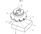
- FIGS. 13 to 15 are schematic diagrams illustrating a method for manufacturing a cut workpiece according to an embodiment of the present disclosure.
- the method for manufacturing a cut workpiece according to the embodiment of the present disclosure is a method for manufacturing a cut workpiece M that is a cut workpiece W that has been subjected to cutting processing. , a first step, a second step, and a third step.
- the first step is a step of rotating the cutting tool 56.
- the second step is a step of bringing the rotating cutting tool 56 into contact with the workpiece W.
- the third step is a step of separating the cutting tool 56 from the workpiece W.
- Examples of the material of the work material W include aluminum alloy, stainless steel, carbon steel, alloy steel, cast iron, and non-ferrous metals.
- the cutting tool 56 is rotated in the rotational direction T and moved in the direction of the arrow FD to approach the workpiece W. Then, the cutting insert 10 of the rotating cutting tool 56 is further moved in the direction of the arrow FD while being brought into contact with the workpiece W. Thereby, the cutting tool 56 performs the cutting process on the workpiece W, and as in the example shown in FIG. 15, a machined surface Wf is formed on the workpiece.
- the cutting tool 56 is moved in the direction of the arrow FD and separated from the workpiece W. Thereby, cutting of the work material W is completed, and a cut workpiece M, which is the cut material W that has been cut, can be manufactured. Since the cutting tool 56 has excellent cutting ability for the reason mentioned above, it is possible to manufacture a cut workpiece M with excellent processing accuracy.
- the cutting insert 10 of the cutting tool 56 may be repeatedly brought into contact with different parts of the workpiece W while the cutting tool 56 is being rotated.
- the cutting tool 56 is brought close to the workpiece W, but since it is sufficient that the cutting tool 56 and the workpiece W are relatively close to each other, for example, the workpiece W is brought close to the cutting tool 56. It's okay. In this regard, when separating the cutting tool 56 from the workpiece W, the same procedure is performed.
- Cutting insert 12 Upper surface 14 Lower surface 16 Side surface 18 Mounting hole 20 Upper cutting edge 22 Lower cutting edge 24 1st corner (corner part) 26 Second corner (other corner section) 28 First side (side part) 28a First part 28b Second part 28c Third part 30 Second side (other side) 32 Land portion 34 Outer inclined surface 34a First outer region 34b Second outer region 34c Third outer region 36 Middle inclined surface 36a First middle region 36b Second middle region 36c Third middle region 38 Inner inclined surface 38a First inner region 38b Second inner region 38c Third inner region 40 Minor inclined surface 42 First corner inclined surface 44 Second corner inclined surface 46 Bottom surface 48 Main cutting edge 50 Minor cutting edge 52 First corner edge 54 Second corner edge 56 Cutting tool 58 Holder 60 Pocket 62 Fixing screw CS Insert center axis PD Direction parallel to insert center axis RS Rotation axis
Landscapes
- Engineering & Computer Science (AREA)
- Mechanical Engineering (AREA)
- Milling Processes (AREA)
Priority Applications (4)
| Application Number | Priority Date | Filing Date | Title |
|---|---|---|---|
| DE112023001375.6T DE112023001375T5 (de) | 2022-03-15 | 2023-03-08 | Schneideinsatz, schneidwerkzeug und verfahren zur herstellung eines maschinell bearbeiteten produkts |
| JP2024507800A JP7733214B2 (ja) | 2022-03-15 | 2023-03-08 | 切削インサート、切削工具、及び切削加工物の製造方法 |
| US18/846,273 US20250196236A1 (en) | 2022-03-15 | 2023-03-08 | Cutting insert, cutting tool, and method for manufacturing machined product |
| CN202380025772.8A CN118829504A (zh) | 2022-03-15 | 2023-03-08 | 切削刀片、切削刀具以及切削加工物的制造方法 |
Applications Claiming Priority (2)
| Application Number | Priority Date | Filing Date | Title |
|---|---|---|---|
| JP2022040643 | 2022-03-15 | ||
| JP2022-040643 | 2022-03-15 |
Publications (1)
| Publication Number | Publication Date |
|---|---|
| WO2023176619A1 true WO2023176619A1 (ja) | 2023-09-21 |
Family
ID=88023128
Family Applications (1)
| Application Number | Title | Priority Date | Filing Date |
|---|---|---|---|
| PCT/JP2023/008796 Ceased WO2023176619A1 (ja) | 2022-03-15 | 2023-03-08 | 切削インサート、切削工具、及び切削加工物の製造方法 |
Country Status (5)
| Country | Link |
|---|---|
| US (1) | US20250196236A1 (https=) |
| JP (1) | JP7733214B2 (https=) |
| CN (1) | CN118829504A (https=) |
| DE (1) | DE112023001375T5 (https=) |
| WO (1) | WO2023176619A1 (https=) |
Cited By (1)
| Publication number | Priority date | Publication date | Assignee | Title |
|---|---|---|---|---|
| EP4620603A2 (en) | 2024-02-02 | 2025-09-24 | Tungaloy Corporation | Cutting insert and a cutting tool comprising the same |
Citations (4)
| Publication number | Priority date | Publication date | Assignee | Title |
|---|---|---|---|---|
| WO2013002341A1 (ja) * | 2011-06-30 | 2013-01-03 | 京セラ株式会社 | 切削インサートおよび切削工具ならびにそれを用いた切削加工物の製造方法 |
| JP2019115941A (ja) * | 2017-12-26 | 2019-07-18 | 株式会社タンガロイ | 切削インサート |
| WO2019230987A1 (ja) * | 2018-06-01 | 2019-12-05 | 京セラ株式会社 | 切削インサート、切削工具及び切削加工物の製造方法 |
| WO2021192499A1 (ja) * | 2020-03-26 | 2021-09-30 | 株式会社Moldino | 切削インサートおよび刃先交換式切削工具 |
Family Cites Families (1)
| Publication number | Priority date | Publication date | Assignee | Title |
|---|---|---|---|---|
| JP7119780B2 (ja) | 2018-08-30 | 2022-08-17 | 三菱マテリアル株式会社 | 切削インサートおよび刃先交換式切削工具 |
-
2023
- 2023-03-08 WO PCT/JP2023/008796 patent/WO2023176619A1/ja not_active Ceased
- 2023-03-08 US US18/846,273 patent/US20250196236A1/en active Pending
- 2023-03-08 DE DE112023001375.6T patent/DE112023001375T5/de active Pending
- 2023-03-08 JP JP2024507800A patent/JP7733214B2/ja active Active
- 2023-03-08 CN CN202380025772.8A patent/CN118829504A/zh active Pending
Patent Citations (4)
| Publication number | Priority date | Publication date | Assignee | Title |
|---|---|---|---|---|
| WO2013002341A1 (ja) * | 2011-06-30 | 2013-01-03 | 京セラ株式会社 | 切削インサートおよび切削工具ならびにそれを用いた切削加工物の製造方法 |
| JP2019115941A (ja) * | 2017-12-26 | 2019-07-18 | 株式会社タンガロイ | 切削インサート |
| WO2019230987A1 (ja) * | 2018-06-01 | 2019-12-05 | 京セラ株式会社 | 切削インサート、切削工具及び切削加工物の製造方法 |
| WO2021192499A1 (ja) * | 2020-03-26 | 2021-09-30 | 株式会社Moldino | 切削インサートおよび刃先交換式切削工具 |
Cited By (1)
| Publication number | Priority date | Publication date | Assignee | Title |
|---|---|---|---|---|
| EP4620603A2 (en) | 2024-02-02 | 2025-09-24 | Tungaloy Corporation | Cutting insert and a cutting tool comprising the same |
Also Published As
| Publication number | Publication date |
|---|---|
| JPWO2023176619A1 (https=) | 2023-09-21 |
| DE112023001375T5 (de) | 2025-01-09 |
| US20250196236A1 (en) | 2025-06-19 |
| CN118829504A (zh) | 2024-10-22 |
| JP7733214B2 (ja) | 2025-09-02 |
Similar Documents
| Publication | Publication Date | Title |
|---|---|---|
| KR101700703B1 (ko) | 절삭 인서트 및 절삭 공구 그리고 그것을 이용한 절삭 가공물의 제조 방법 | |
| KR101720553B1 (ko) | 절삭 인서트, 절삭 공구 및 절삭 가공물의 제조 방법 | |
| JP5591409B2 (ja) | 切削インサート、切削工具および被削加工物の製造方法 | |
| CN111902232B (zh) | 切削刀片、切削工具及切削加工物的制造方法 | |
| US12325078B2 (en) | Cutting insert, cutting tool, and method for manufacturing machined product | |
| JP7480291B2 (ja) | 切削インサート、切削工具及び切削加工物の製造方法 | |
| CN111148590B (zh) | 切削刀片、切削刀具以及切削加工物的制造方法 | |
| US12337400B2 (en) | Rotary tool and method for manufacturing machined product | |
| US10406610B2 (en) | Cutting insert, cutting tool, and method of manufacturing machined product | |
| JPWO2018012463A1 (ja) | 切削インサート、切削工具及び切削加工物の製造方法 | |
| JP6711842B2 (ja) | 切削インサート、切削工具及び切削加工物の製造方法 | |
| JP6185376B2 (ja) | 切削インサート、切削工具および被削加工物の製造方法 | |
| CN110944777B (zh) | 切削刀片、切削工具以及切削加工物的制造方法 | |
| WO2023176619A1 (ja) | 切削インサート、切削工具、及び切削加工物の製造方法 | |
| JPWO2017073663A1 (ja) | 切削工具用ホルダ、切削工具及び切削加工物の製造方法 | |
| JP7325510B2 (ja) | 切削インサート、切削工具及び切削加工物の製造方法 | |
| JP5815858B2 (ja) | 切削インサート、切削工具および被削加工物の製造方法 | |
| JP7114733B2 (ja) | 切削インサート、切削工具及び切削加工物の製造方法 | |
| WO2021095520A1 (ja) | 切削インサート、切削工具及び切削加工物の製造方法 | |
| WO2024048257A1 (ja) | 切削インサート、切削工具、及び切削加工物の製造方法 | |
| KR102540681B1 (ko) | 절삭 인서트, 절삭 공구 및 절삭 가공물의 제조 방법 | |
| JP7706641B2 (ja) | 切削インサート、切削工具、及び切削加工物の製造方法 | |
| JP6685532B2 (ja) | 切削インサート、切削工具及び切削加工物の製造方法 | |
| JP6616176B2 (ja) | 切削工具 | |
| JP2012232351A (ja) | 切削インサートおよび切削工具ならびにそれを用いた被削材の切削方法 |
Legal Events
| Date | Code | Title | Description |
|---|---|---|---|
| 121 | Ep: the epo has been informed by wipo that ep was designated in this application |
Ref document number: 23770575 Country of ref document: EP Kind code of ref document: A1 |
|
| WWE | Wipo information: entry into national phase |
Ref document number: 202380025772.8 Country of ref document: CN |
|
| ENP | Entry into the national phase |
Ref document number: 2024507800 Country of ref document: JP Kind code of ref document: A |
|
| WWE | Wipo information: entry into national phase |
Ref document number: 18846273 Country of ref document: US |
|
| WWE | Wipo information: entry into national phase |
Ref document number: 112023001375 Country of ref document: DE |
|
| 122 | Ep: pct application non-entry in european phase |
Ref document number: 23770575 Country of ref document: EP Kind code of ref document: A1 |
|
| WWP | Wipo information: published in national office |
Ref document number: 18846273 Country of ref document: US |