WO2023176265A1 - 車両用灯具 - Google Patents
車両用灯具 Download PDFInfo
- Publication number
- WO2023176265A1 WO2023176265A1 PCT/JP2023/005242 JP2023005242W WO2023176265A1 WO 2023176265 A1 WO2023176265 A1 WO 2023176265A1 JP 2023005242 W JP2023005242 W JP 2023005242W WO 2023176265 A1 WO2023176265 A1 WO 2023176265A1
- Authority
- WO
- WIPO (PCT)
- Prior art keywords
- light
- light emitting
- light emission
- function
- color
- Prior art date
- Legal status (The legal status is an assumption and is not a legal conclusion. Google has not performed a legal analysis and makes no representation as to the accuracy of the status listed.)
- Ceased
Links
Images





Classifications
-
- B—PERFORMING OPERATIONS; TRANSPORTING
- B60—VEHICLES IN GENERAL
- B60Q—ARRANGEMENT OF SIGNALLING OR LIGHTING DEVICES, THE MOUNTING OR SUPPORTING THEREOF OR CIRCUITS THEREFOR, FOR VEHICLES IN GENERAL
- B60Q1/00—Arrangement of optical signalling or lighting devices, the mounting or supporting thereof or circuits therefor
-
- B—PERFORMING OPERATIONS; TRANSPORTING
- B60—VEHICLES IN GENERAL
- B60Q—ARRANGEMENT OF SIGNALLING OR LIGHTING DEVICES, THE MOUNTING OR SUPPORTING THEREOF OR CIRCUITS THEREFOR, FOR VEHICLES IN GENERAL
- B60Q1/00—Arrangement of optical signalling or lighting devices, the mounting or supporting thereof or circuits therefor
- B60Q1/02—Arrangement of optical signalling or lighting devices, the mounting or supporting thereof or circuits therefor the devices being primarily intended to illuminate the way ahead or to illuminate other areas of way or environments
- B60Q1/04—Arrangement of optical signalling or lighting devices, the mounting or supporting thereof or circuits therefor the devices being primarily intended to illuminate the way ahead or to illuminate other areas of way or environments the devices being headlights
-
- B—PERFORMING OPERATIONS; TRANSPORTING
- B60—VEHICLES IN GENERAL
- B60Q—ARRANGEMENT OF SIGNALLING OR LIGHTING DEVICES, THE MOUNTING OR SUPPORTING THEREOF OR CIRCUITS THEREFOR, FOR VEHICLES IN GENERAL
- B60Q1/00—Arrangement of optical signalling or lighting devices, the mounting or supporting thereof or circuits therefor
- B60Q1/26—Arrangement of optical signalling or lighting devices, the mounting or supporting thereof or circuits therefor the devices being primarily intended to indicate the vehicle, or parts thereof, or to give signals, to other traffic
- B60Q1/34—Arrangement of optical signalling or lighting devices, the mounting or supporting thereof or circuits therefor the devices being primarily intended to indicate the vehicle, or parts thereof, or to give signals, to other traffic for indicating change of drive direction
-
- B—PERFORMING OPERATIONS; TRANSPORTING
- B60—VEHICLES IN GENERAL
- B60Q—ARRANGEMENT OF SIGNALLING OR LIGHTING DEVICES, THE MOUNTING OR SUPPORTING THEREOF OR CIRCUITS THEREFOR, FOR VEHICLES IN GENERAL
- B60Q1/00—Arrangement of optical signalling or lighting devices, the mounting or supporting thereof or circuits therefor
- B60Q1/26—Arrangement of optical signalling or lighting devices, the mounting or supporting thereof or circuits therefor the devices being primarily intended to indicate the vehicle, or parts thereof, or to give signals, to other traffic
- B60Q1/34—Arrangement of optical signalling or lighting devices, the mounting or supporting thereof or circuits therefor the devices being primarily intended to indicate the vehicle, or parts thereof, or to give signals, to other traffic for indicating change of drive direction
- B60Q1/38—Arrangement of optical signalling or lighting devices, the mounting or supporting thereof or circuits therefor the devices being primarily intended to indicate the vehicle, or parts thereof, or to give signals, to other traffic for indicating change of drive direction using immovably-mounted light sources, e.g. fixed flashing lamps
-
- B—PERFORMING OPERATIONS; TRANSPORTING
- B60—VEHICLES IN GENERAL
- B60Q—ARRANGEMENT OF SIGNALLING OR LIGHTING DEVICES, THE MOUNTING OR SUPPORTING THEREOF OR CIRCUITS THEREFOR, FOR VEHICLES IN GENERAL
- B60Q1/00—Arrangement of optical signalling or lighting devices, the mounting or supporting thereof or circuits therefor
- B60Q1/26—Arrangement of optical signalling or lighting devices, the mounting or supporting thereof or circuits therefor the devices being primarily intended to indicate the vehicle, or parts thereof, or to give signals, to other traffic
- B60Q1/44—Arrangement of optical signalling or lighting devices, the mounting or supporting thereof or circuits therefor the devices being primarily intended to indicate the vehicle, or parts thereof, or to give signals, to other traffic for indicating braking action or preparation for braking, e.g. by detection of the foot approaching the brake pedal
-
- F—MECHANICAL ENGINEERING; LIGHTING; HEATING; WEAPONS; BLASTING
- F21—LIGHTING
- F21V—FUNCTIONAL FEATURES OR DETAILS OF LIGHTING DEVICES OR SYSTEMS THEREOF; STRUCTURAL COMBINATIONS OF LIGHTING DEVICES WITH OTHER ARTICLES, NOT OTHERWISE PROVIDED FOR
- F21V5/00—Refractors for light sources
-
- H—ELECTRICITY
- H05—ELECTRIC TECHNIQUES NOT OTHERWISE PROVIDED FOR
- H05B—ELECTRIC HEATING; ELECTRIC LIGHT SOURCES NOT OTHERWISE PROVIDED FOR; CIRCUIT ARRANGEMENTS FOR ELECTRIC LIGHT SOURCES, IN GENERAL
- H05B45/00—Circuit arrangements for operating light-emitting diodes [LED]
- H05B45/20—Controlling the colour of the light
-
- H—ELECTRICITY
- H05—ELECTRIC TECHNIQUES NOT OTHERWISE PROVIDED FOR
- H05B—ELECTRIC HEATING; ELECTRIC LIGHT SOURCES NOT OTHERWISE PROVIDED FOR; CIRCUIT ARRANGEMENTS FOR ELECTRIC LIGHT SOURCES, IN GENERAL
- H05B47/00—Circuit arrangements for operating light sources in general, i.e. where the type of light source is not relevant
- H05B47/10—Controlling the light source
- H05B47/155—Coordinated control of two or more light sources
-
- H—ELECTRICITY
- H05—ELECTRIC TECHNIQUES NOT OTHERWISE PROVIDED FOR
- H05B—ELECTRIC HEATING; ELECTRIC LIGHT SOURCES NOT OTHERWISE PROVIDED FOR; CIRCUIT ARRANGEMENTS FOR ELECTRIC LIGHT SOURCES, IN GENERAL
- H05B47/00—Circuit arrangements for operating light sources in general, i.e. where the type of light source is not relevant
- H05B47/10—Controlling the light source
- H05B47/16—Controlling the light source by timing means
-
- H—ELECTRICITY
- H05—ELECTRIC TECHNIQUES NOT OTHERWISE PROVIDED FOR
- H05B—ELECTRIC HEATING; ELECTRIC LIGHT SOURCES NOT OTHERWISE PROVIDED FOR; CIRCUIT ARRANGEMENTS FOR ELECTRIC LIGHT SOURCES, IN GENERAL
- H05B47/00—Circuit arrangements for operating light sources in general, i.e. where the type of light source is not relevant
- H05B47/10—Controlling the light source
- H05B47/165—Controlling the light source following a pre-assigned programmed sequence; Logic control [LC]
Definitions
- the present invention relates to a vehicle lamp, and more particularly, to a technology for a vehicle lamp that can emit light in multiple colors.
- a combination lamp that combines the functions of a DRL (Daytime Running Lamp) and a turn signal lamp is applicable.
- the emitted light color changes when the function is switched.
- a light emitting element that emits white light and a light emitting element that emits amber color are arranged adjacent to each other, thereby providing a DRL function and a turn signal lamp function in one lighting unit. A configuration is disclosed.
- the present invention aims to solve the above-mentioned problems, and aims to appropriately notify the switching of the function of a lamp.
- the vehicle lamp of the present invention includes a light emitting section having a plurality of light emitting elements, and the light emitting section emits light in a first color while a first function is being performed, and the light emitting section emits light in a first color while a second function is being performed.
- a vehicular lamp that emits light in a second emission color, and during a switching period in which switching from the first function to the second function is performed, the first light emission region of the light emitting part is changed to the first emission color.
- the light emitting device further includes a light emission control section that causes a second light emitting region different from the first light emitting region of the light emitting section to emit light in a second light emitting color.
- one vehicle lamp has multiple functions, it is conceivable to use the functions depending on the color of the light emitted from the light emitting part. At this time, by providing light-emitting regions with different light-emitting colors at the same time, it is possible for other vehicles, pedestrians, etc. to recognize that the function is being switched.
- switching of the function of a lamp can be appropriately notified.
- FIG. 1 is a schematic diagram showing the appearance of a vehicle of the present invention.
- FIG. 1 is a block diagram showing a partial configuration of a vehicle according to the present invention.
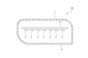
- FIG. 2 is a schematic cross-sectional view of a configuration example of a vehicle lamp.
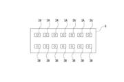
- FIG. 2 is a schematic diagram showing an example of arrangement of light emitting elements on a substrate.
- FIG. 7 is a schematic diagram showing another example of arrangement of light emitting elements on a substrate.
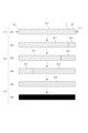
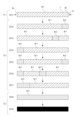
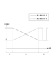
- FIG. 3 is a diagram for explaining a first example of a light emission mode. It is a figure for demonstrating the 2nd example of a light emission aspect. It is a figure for demonstrating the 3rd example of a light emission aspect. It is a figure for demonstrating the 4th example of a light emission aspect. It is a figure for explaining the 5th example of a light emission aspect.
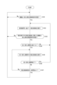
- 3 is a flowchart showing the flow of processing by a light emission control section.
- the configuration of a vehicle lamp 1 according to this embodiment will be described with reference to FIG. 1.
- the vehicle lamp 1 includes a light emitting element and an electronic circuit necessary for causing the light emitting element to emit light, and is installed in each part of the vehicle 100.
- examples of the vehicle lamp 1 include a right lamp unit 1R attached to the front right side of a vehicle 100 and a left lamp unit 1L attached to the left side of the vehicle 100.
- the right lamp unit 1R and the left lamp unit 1L are provided as lamps that have both a DRL (Daytime Running Lamp) function and a turn signal lamp function, respectively. That is, the right lamp unit 1R and the left lamp unit 1L are capable of emitting white light and amber light.
- DRL Daytime Running Lamp
- the right lamp unit 1R includes a light emission control section 2, a plurality of light emitting elements 3, and a cover lens 4.
- the plurality of light emitting elements 3 and cover lens 4 form a light emitting section 5.
- the light emitting section 5 may include a diffusion plate (not shown) that diffuses light. By providing the light emitting section 5 with the diffuser plate, it becomes possible to uniformly emit light from the entire light emitting section 5 regardless of the arrangement of the light emitting elements 3.
- the left side lamp unit 1L has the same configuration as the right side lamp unit 1R, and specifically includes a light emission control section 2, a plurality of light emitting elements 3, and a cover lens 4, and the light emitting elements 3 and the cover lens 4 are connected to each other.
- a light emitting section 5 is formed.
- the light emission control unit 2 supplies a drive voltage to each light emitting element 3 based on a control signal from a lamp ECU (Electronic Control Unit) 6 provided on the vehicle side, thereby causing the light emitting element 3 to perform a predetermined light emitting operation. This realizes various light emission modes by the light emitting section 5.
- a lamp ECU Electronic Control Unit
- the lamp ECU 6 is configured to include an arithmetic processing unit and a storage unit, and receives instruction information from a higher-level control unit that controls the entire vehicle, such as a vehicle control ECU, and sends instruction information to each vehicle lamp 1. outputs a control signal.
- FIG. 3 is a horizontal sectional view of the right lamp unit 1R, which is an example of the vehicle lamp 1.
- the right lamp unit 1R includes a lamp body 7 that is open at the front and a transparent cover lens 4 that closes the opening from the front, and a substrate 8 is disposed in the internal space.
- a plurality of light emitting elements 3 are arranged on the substrate 8 and spaced apart from each other in the left-right direction (vehicle width direction).
- the light emitting element 3 is, for example, an LED (Light Emitting Diode).
- the first light emitting element 3A is the light emitting element 3 for realizing the DRL function and can emit light only in white color
- the light emitting element 3 for realizing the turn signal lamp function is capable of emitting light only in amber color.
- Both of the second light emitting elements 3B may be arranged on the substrate 8 (see FIG. 4).
- the first light emitting element 3A and the second light emitting element 3B are arranged vertically separately, but the arrangement mode is not limited to this.
- the first light emitting elements 3A and the second light emitting elements 3B may be arranged alternately in the vertical and horizontal directions.
- a third light emitting element 3C (such as a full color LED) which is a light emitting element 3 that can realize both the DRL function and the turn signal lamp function and can emit light in full color may be arranged on the substrate 8 (Fig. 5 reference).
- the light emission control unit 2 performs light emission control for realizing the DRL function and light emission control for realizing the turn signal lamp function. Further, in order to cause (switch) the turn signal lamp function while the DRL function is being expressed, the light emission control unit 2 performs light emission control during the switching period (hereinafter referred to as "light emission control during switching").
- the light emission control unit 2 controls the light emission unit 5 to emit white light as a light emission mode indicating that the DRL function is being expressed (state ST1 in the figure).
- the region emitting white light is referred to as a first light emitting region Ar1. That is, state ST1 indicates that the entire light emitting section 5 emits white light.
- the state in which the light emission mode indicating that the DRL function is being performed is a state in which a light emission instruction for DRL is inputted to the light emission control unit 2 from the lamp ECU 6, for example, the light emission instruction for DRL is inputted from the lamp ECU 6.
- a light emission instruction for DRL is inputted to the light emission control unit 2 from the lamp ECU 6, for example, the light emission instruction for DRL is inputted from the lamp ECU 6.
- the DRL signal and turn signal signal only the DRL signal is turned ON.
- first period T1 the period during which the light emission mode indicating that the DRL function is being performed.
- the light emission control unit 2 executes light emission control during switching.
- the state in which an instruction indicating switching to the turn signal lamp function is input to the light emission control unit 2 is, for example, a state in which both the DRL signal and the turn signal signal input from the lamp ECU 6 are turned ON.
- the period during which the light emission control during switching is executed is referred to as a "second period T2."
- the light emission control section 2 controls the light emitting region of the light emitting section 5 from the vehicle inner end 5i to the vehicle outer end 5o.
- the light emission is controlled so that it spreads.
- the amber light emitting area is referred to as a second light emitting area Ar2.
- the light emission control section 2 After the second period T2, the light emission control section 2 performs light emission control on the light emitting section 5 to indicate to the surroundings that the turn signal lamp function is being performed.
- the period during which this light emission control is performed is referred to as a "third period T3.”
- Second example> The light emission mode of the second example will be explained with reference to FIG. 7.
- the light emission control section 2 controls the light emission section 5 to emit white light as a light emission mode indicating that the DRL function is being expressed (state ST11 in FIG. 7).
- the light emission control unit 2 After a first period T1 during which light emission control is performed indicating that the DRL function is being activated, the light emission control unit 2 changes a part of the area of the light emission unit 5 on the vehicle inner side end 5i to an amber color, as shown in state ST12. Performs light emission control to emit light. At this time, this part of the amber region is set as the second light emitting region Ar2.
- the light emission control unit 2 performs light emission control such that the second light emitting region Ar2 located on the vehicle inner end 5i side moves toward the vehicle outer end 5o side, as shown in states ST13 and ST14.
- the light emitting control unit 2 moves the second second light emitting region Ar2 to the vehicle inner end 5i, as shown in state ST15. Light emission control is performed.
- the light emission control unit 2 performs light emission control so that the second light emission region Ar2 located on the vehicle inner end 5i side moves toward the vehicle outer end 5o side, as shown in states ST16 and ST17.
- the light emission control section 2 performs light emission control (state ST18) such that the entire light emitting section 5 emits light in amber color, that is, the entire light emitting section 5 becomes the second light emitting area Ar2; Control to turn off the entire area of the section 5 (state ST19) is performed alternately.
- the light emission control unit 2 performs the first light emission in which the entire light emission unit 5 emits white light, as shown in state ST11 in FIG. Light emission control is performed so that the area becomes the area Ar1.
- the light emission control section 2 controls the light emission section 5 at the outer side of the vehicle, as shown in states ST12, ST13, ST14, ST15, ST16, and ST17 in the figure.
- Light emission control is performed so that the second light emitting areas Ar2 generated on the side of the portion 5o are moved toward the side of the inner side of the vehicle 5i so that the second light emitting areas Ar2 are piled up on the side of the inner side of the vehicle 5i.
- the light emission control section 2 controls the light emitting section 5 to be entirely in the second light emitting region, as shown in states ST18 and ST19 in the figure. Light emission control to achieve Ar2 and control to turn off the entire area of the light emitting section 5 are performed alternately.
- the first light emitting element 3A since the light emission mode indicates that the DRL function is being expressed, only the first light emitting element 3A is turned ON (light emission), and the second light emitting element 3B is turned OFF (lights out).
- the light emitting mode indicates that the turn signal lamp function is being activated, so the first light emitting element 3A is turned off (lights out), and the second light emitting element 3B is turned on (light emission). OFF (lights out) is repeated at regular intervals.
- each period Ti consists of a first half period Tia and a second half period Tib, and in the first half period Tia, the first light emitting element 3A is turned OFF (extinguished) and the second light emitting element 3B is turned ON (light emitted). Further, in the second half period Tib, the first light emitting element 3A is turned on (light emission), and the second light emitting element 3B is turned off (light extinguished).
- the light emitting section 5 emits white light
- the light emitting section 5 emits light in amber color
- the first half period Ti1a is shortened and the second half period Ti1b is lengthened.
- the first half period Tia is gradually lengthened and the second half period Tib is gradually shortened. That is, in the second period T2, control to emit white light and control to emit amber color are performed alternately, and the time to emit white light is gradually shortened and the time to emit amber color is gradually lengthened.
- the light emission mode of the fifth example will be explained with reference to FIG. 10. As described above, the first light emitting element 3A emits only white light, and the second light emitting element 3B emits only amber light.
- the first light emitting element 3A is turned ON (light emitting), and the second light emitting element 3B is turned OFF (light extinguished).
- the first light emitting element 3A is turned off (lights out), and the second light emitting element 3B is turned on (light emission) and off (lights out) repeatedly at regular intervals.
- the light emission intensity of the first light emitting element 3A decreases as time passes, and the light emission intensity of the second light emitting element 3B increases instead.
- the color of the light emitted from the light emitting section 5 gradually changes from white to amber.
- step S101 the light emission control unit 2 determines whether a light emission control instruction related to a certain function has been received. Specifically, if a certain function is a DRL function, whether or not a light emission control instruction (DRL signal is ON and turn signal signal is OFF) to notify the surroundings that the DRL function is being activated is received. Determine.
- DRL signal is ON and turn signal signal is OFF
- a certain function is a turn signal lamp function
- whether a light emission control instruction (the turn signal signal is ON regardless of the DRL signal) to notify the surroundings that the turn signal lamp function is being activated is received. Determine whether or not.
- step S101 If it is determined in the determination process of step S101 that the signal has not been received, the light emission control unit 2 repeatedly executes the process of step S101.
- the light emission control unit 2 executes light emission control based on the received signal in step S102.
- light emission control control for causing the light emitting unit 5 to emit white light
- step S103 the light emission control unit 2 determines whether or not a light emission control instruction related to a function different from the light emission control currently being executed has been received. For example, if the turn signal signal is changed from OFF to ON while executing light emission control based on the DRL function, it is determined that a light emission control instruction related to a different function has been received.
- the DRL signal is turned ON and the turn signal lamp function is turned OFF while executing light emission control based on the turn signal lamp function, the light emission control based on the turn signal lamp function is stopped and the light emission control based on the DRL function is It can be considered that an instruction has been given to start (resume). That is, in this case, it is determined that a light emission control instruction related to a different function has been received.
- the light emission control unit 2 continues to execute the currently executed light emission control by repeatedly executing steps S101, S102, and S103.
- the light emission control unit 2 proceeds to step S104 and determines whether or not to provide a switching period. For example, when transitioning from the DRL function to the turn signal lamp function, it may be determined that a switching period is provided, and when transitioning from the turn signal lamp function to the DRL function, it may be determined that no switching period is provided. .
- the light emission control unit 2 returns to step S102 and executes light emission control based on the newly received instruction (the previous light emission control instruction related to a different function). Thereby, for example, switching from the turn signal lamp function to the DRL function is performed without providing a switching period.
- the light emission control unit 2 executes light emission control during the switching period in step S105.
- This light emission control is the light emission control executed in the second period T2 described above.
- step S106 the light emission control unit 2 determines whether the switching period has ended. If it is determined that the switching period has ended, the light emission control unit 2 returns to step S102 and executes light emission control based on the newly received instruction (the previous light emission control instruction related to a different function). Thereby, for example, switching from the DRL function to the turn signal lamp function is performed after a switching period.
- step S106 determines in step S107 whether there is a change in the light emission control instruction.
- the light emission control unit 2 returns to step S101, confirms the light emission control instruction again, and executes light emission control based on the light emission control instruction (step S102).
- step S105 if it is determined that there is no change in the light emission control instruction, that is, if the switching period has not ended and the light emission control instruction has not been changed, the light emission control unit 2 continues the process of step S105.
- the light emission control unit 2 By executing the series of processes shown in FIG. 11 by the light emission control unit 2, the light emission control for the DRL function in the light emission unit 5, the light emission control for the turn signal lamp function, and the light emission control when these functions are switched. will be held.
- the vehicle lamp 1 described above is not limited to the left lamp unit 1L and the right lamp unit 1R.
- a part of a headlamp or fog lamp attached to the front side of the vehicle 100, a tail lamp, a stop lamp, a hazard lamp, a back lamp, etc. attached to the rear side of the vehicle 100 may be combined. It is applicable to various combination lamps. That is, the vehicle lamp 1 described above is applicable to the case where a plurality of functions are realized by one lamp.
- the first example is the welcome light function in tail lamps, stop lamps, etc.
- the welcome light function causes some of the vehicle lamps 1 to emit light in a predetermined light emission pattern when getting on or off the vehicle 100. For example, as an example of light emission control when getting off the vehicle 100, consider changing the vehicular lamp 1 from the first emission color (red) to the second emission color (blue, turquoise).
- the light emission in the first color is, for example, light emission for a function (first function) for notifying that the shift lever of the vehicle 100 is in the parking range.
- the light emission in the second light emission color is the light emission for a function (second function) for notifying that each door of the vehicle 100 is locked by a smart key or the like.
- the color of the light emitted by the clearance lamp function is white (first function) to indicate that the door is locked.
- the color may be changed to blue (second function), which is the emission color for the function to notify the user.
- the second example concerns autonomous driving.
- a clearance lamp provided at the front of the vehicle and a portion of a tail lamp provided at the rear of the vehicle (for example, only the center portion in the left-right direction of the tail lamp) as the vehicle lamp 1 of the vehicle 100 may be used as the first function (clearance lamp function).
- the second function (a function to notify that automatic driving is in progress) emit light in different colors.
- the clearance lamp provided on the front of the vehicle 100 emits white light in the first function, and blue (turquoise) light in the second function. Further, a part of the tail lamp provided on the rear surface of the vehicle 100 emits red light in the first function and blue (turquoise color) in the second function.
- the light emitting unit 5 is switched from the second function to the first function.
- a third example is a vehicle lamp 1 that is provided on the rear surface of the vehicle 100 and serves as both a tail lamp and a turn signal lamp.
- the first function tail lamp function
- the second function causes the vehicle lamp 1 to emit light in amber color.
- the vehicle lamp 1 such as the right side lamp unit 1R and the left side lamp unit 1L described above includes a light emitting section 5 having a plurality of light emitting elements 3, and when the first function (for example, DRL function) is being performed, the light emitting section 5 is The vehicle lamp 1 emits light in a first color (e.g., white), and the light emitting part 5 emits light in a second color (e.g., amber color) while the second function (e.g., turn signal lamp function) is being performed.
- a first color e.g., white
- the light emitting part 5 emits light in a second color (e.g., amber color) while the second function (e.g., turn signal lamp function) is being performed.
- the light emitting controller 2 includes a light emitting control section 2 that causes the two light emitting regions Ar2 to emit light in a second light emitting color.
- the light emitting control section 2 of the vehicle lamp 1 changes the second light emitting region Ar2, which is a region of the light emitting section 5 at one end (vehicle inner end 5i or vehicle outer end 5o), from the other end (vehicle outer end 5o).
- the light emission may be controlled so as to spread toward the outer end 5o or the vehicle inner end 5i). That is, during the switching period, as time passes, the first light emitting region Ar1 that emits light with the first light emitting color is reduced, and the second light emitting region Ar2 that emits light with the second light emitting color is expanded. Therefore, it becomes possible to intuitively recognize that the function is to be switched.
- the light emitting control section 2 of the vehicle lamp 1 changes the second light emitting region Ar2, which is a region of the light emitting section 5 at one end (vehicle inner end 5i or vehicle outer end 5o), from the other end (vehicle outer end 5o).
- the light emission may be controlled so as to move toward the outer end 5o or the vehicle inner end 5i).
- the direction similar to the sequential lighting control of the turn signal lamp when turning right or left from the vehicle inner end 5i side to the vehicle
- the second light emitting regions Ar2 are stacked up in the direction (direction toward the outer end 5o)
- the light emitting unit 5 of the vehicle lamp 1 includes a plurality of light emitting elements 3 including a first light emitting element 3A capable of emitting light of a first color but not of a second color, and a first light emitting element 3A capable of emitting light of a second color.
- a second light emitting element 3B that is capable of emitting light of the first color and not capable of emitting light of the first color may be included.
- the first light emitting element 3A is capable of emitting light of only the first color
- the second light emitting element 3B is capable of emitting light of only the second color.
- an example of a light-emitting element that can emit light in multiple colors is a full-color LED, but in that case, if a failure occurs in which some of the RGB LEDs are unable to emit light, unintended light emission may occur. There is a possibility that the light emitting unit 5 will emit light depending on the color. In addition, there is a possibility that people around the vehicle may misidentify the vehicle due to the malfunction. According to this configuration, there is no possibility that the light emitting unit 5 will emit light in an unintended color, and therefore there is no possibility of giving wrong recognition to the surroundings, which is preferable.
- the light emitting unit 5 of the vehicle lamp 1 may include, as the plurality of light emitting elements 3, a light emitting element (third light emitting element 3C) capable of emitting light of a first color and a second color.
- the light emitting element 3 included in the light emitting section 5 is a full color LED.
- Vehicle light 1R Right side lamp unit (vehicle light) 1L left side lamp unit (vehicle light) 2 Light emission control section 3 Light emitting element 3A First light emitting element 3B Second light emitting element 3C Third light emitting element (light emitting element) 5 Light emitting part 5i Vehicle inner end (one end, other end) 5o Vehicle outer end (one end, other end) Ar1 First light emitting area Ar2 Second light emitting area T2 Second period (switching period)
Landscapes
- Engineering & Computer Science (AREA)
- Mechanical Engineering (AREA)
- General Engineering & Computer Science (AREA)
- Lighting Device Outwards From Vehicle And Optical Signal (AREA)
Abstract
車両用灯具は、複数の発光素子を有する発光部を備えると共に、第1機能の発現中においては前記発光部が第1発光色で発光され第2機能の発現中においては前記発光部が第2発光色で発光される車両用灯具であって、前記第1機能から前記第2機能への切り替えが行われる切り替え期間中において、前記発光部における第1発光領域を前記第1発光色で発光させ前記発光部における前記第1発光領域とは異なる第2発光領域を前記第2発光色で発光させる発光制御部を備えるものとした。
Description
本発明は車両用灯具に関し、複数色の発光が可能な車両用灯具についての技術に関する。
車両用灯具においては、部品点数の削減及び組み立て工数の削減のために複数の役割を持たせた灯具が存在する。例えば、DRL(Daytime Running Lamp)としての機能とターンシグナルランプとしての機能などを合わせたコンビネーションランプなどが該当する。
このような灯具では、機能の切り替わりにおいて発光色が変わる。例えば、下記特許文献1においては、白色で発光する発光素子とアンバー色で発光する発光素子を隣接させて配置することにより、DRLの機能とターンシグナルランプとしての機能を一つの灯具ユニットに持たせた構成が開示されている。
このような灯具では、機能の切り替わりにおいて発光色が変わる。例えば、下記特許文献1においては、白色で発光する発光素子とアンバー色で発光する発光素子を隣接させて配置することにより、DRLの機能とターンシグナルランプとしての機能を一つの灯具ユニットに持たせた構成が開示されている。
ところで、機能の切り替わりを周囲の車両や歩行者等に認識させることは重要である。例えば、特許文献1の例においては、点灯する発光素子が切り替わることで灯具の機能がDRLからターンシグナルランプへと切り替わるが、機能の切り替わりを適切に周囲に周知できていない虞がある。
本発明は、上記問題点の解決を図るものであり、灯具の機能の切り替わりを適切に周知することを目的とする。
本発明の車両用灯具は、複数の発光素子を有する発光部を備えると共に、第1機能の発現中においては前記発光部が第1発光色で発光され第2機能の発現中においては前記発光部が第2発光色で発光される車両用灯具であって、前記第1機能から前記第2機能への切り替えが行われる切り替え期間中において、前記発光部における第1発光領域を前記第1発光色で発光させ前記発光部における前記第1発光領域とは異なる第2発光領域を第2発光色で発光させる発光制御部を備えたものである。
一つの車両用灯具が複数の機能を兼用している場合には、発光部の発光色によって機能を使い分けることが考えられる。このとき、発光色の異なる発光領域が同時に設けられることで機能の切り替え期間中であることが他車両及び歩行者等から認識することが可能とされる。
一つの車両用灯具が複数の機能を兼用している場合には、発光部の発光色によって機能を使い分けることが考えられる。このとき、発光色の異なる発光領域が同時に設けられることで機能の切り替え期間中であることが他車両及び歩行者等から認識することが可能とされる。
本発明によれば、灯具の機能の切り替わりを適切に周知することができる。
<1.車両用灯具の構成>
図1を参照して本実施の形態についての車両用灯具1の構成について説明する。
車両用灯具1は、内部に発光素子や該発光素子を発光させるために必要な電子回路等を備えて構成されており、車両100の各部に搭載されている。
図1を参照して本実施の形態についての車両用灯具1の構成について説明する。
車両用灯具1は、内部に発光素子や該発光素子を発光させるために必要な電子回路等を備えて構成されており、車両100の各部に搭載されている。
以降では、車両100のフロント側の左右両端部に取り付けられた車両用灯具1を対象として説明を行う。具体的には、図1に示すように、車両用灯具1として、車両100のフロント右側に取り付けられる右側ランプユニット1Rと、同左側に取り付けられる左側ランプユニット1Lを例に挙げる。
右側ランプユニット1Rと左側ランプユニット1Lは、それぞれDRL(Daytime Running Lamp)機能とターンシグナルランプ機能とを兼用する灯具として設けられている。即ち、右側ランプユニット1Rと左側ランプユニット1Lは、白色で発光可能とされると共にアンバー色で発光可能とされている。
右側ランプユニット1Rは、図2に示すように、発光制御部2と複数の発光素子3とカバーレンズ4とを備えている。複数の発光素子3とカバーレンズ4は発光部5を形成している。なお、光を拡散する拡散板(不図示)が発光部5に含まれていてもよい。発光部5が拡散板を備えることにより、発光素子3の配置によらず発光部5の全体を均一に発光させることが可能となる。
左側ランプユニット1Lは右側ランプユニット1Rと同様の構成とされており、具体的には、発光制御部2と複数の発光素子3とカバーレンズ4とを備え、発光素子3とカバーレンズ4とが発光部5を形成している。
発光制御部2は、車両側に設けられるランプECU(Electronic Control Unit)6からの制御信号に基づいてそれぞれの発光素子3に駆動電圧を供給することで、発光素子3に所定の発光動作を実行させ、発光部5による種々の発光態様を実現する。
ランプECU6は、演算処理部や記憶部を有して構成されており、例えば、車両全体を制御する上位の制御部、例えば車両制御ECUなどから指示情報を受信して各車両用灯具1に対して制御信号を出力する。
車両用灯具1の構成例を図3に示す。なお、図3は、車両用灯具1の一例である右側ランプユニット1Rの水平断面図である。
右側ランプユニット1Rは、前方に開口されたランプボディ7と、該開口を前方から閉塞する透明のカバーレンズ4とを備え、内部空間に基板8が配置されている。
基板8には、左右方向(車幅方向)に離隔して配置される複数の発光素子3が配置されている。発光素子3は、例えば、LED(Light Emitting Diode)などとされる。
発光素子3としては各種のものを採用することが可能である。
例えば、DRL機能を実現するための発光素子3であって白色でのみ発光可能な第1発光素子3Aと、ターンシグナルランプ機能を実現するための発光素子3であってアンバー色でのみ発光可能な第2発光素子3Bの双方を基板8上に配置してもよい(図4参照)。
例えば、DRL機能を実現するための発光素子3であって白色でのみ発光可能な第1発光素子3Aと、ターンシグナルランプ機能を実現するための発光素子3であってアンバー色でのみ発光可能な第2発光素子3Bの双方を基板8上に配置してもよい(図4参照)。
なお、図4では、第1発光素子3Aと第2発光素子3Bがそれぞれ上下に分かれて配置されているが、配置態様はこれに限らない。例えば、上下方向及び左右方向に第1発光素子3Aと第2発光素子3Bが交互に配置されてもよい。
また、DRL機能とターンシグナルランプ機能の双方を実現可能な発光素子3であって、フルカラーで発光可能な第3発光素子3C(フルカラーLEDなど)を基板8上に配置してもよい(図5参照)。
<2.発光態様>
発光制御部2は、DRL機能を実現するための発光制御と、ターンシグナルランプ機能を実現するための発光制御と、を行う。また、DRL機能の発現中にターンシグナルランプ機能を発現させる(切り替える)ために、発光制御部2は切り替え期間中を設けて発光制御(以降、「切替中発光制御」と記載)を行う。
発光制御部2は、DRL機能を実現するための発光制御と、ターンシグナルランプ機能を実現するための発光制御と、を行う。また、DRL機能の発現中にターンシグナルランプ機能を発現させる(切り替える)ために、発光制御部2は切り替え期間中を設けて発光制御(以降、「切替中発光制御」と記載)を行う。
ここでは、発光制御部2による発光部5の発光態様について幾つかの例を説明する。
<2-1.第1例>
第1例の発光態様の変化について図6を参照して説明する。
先ず、発光制御部2はDRL機能を発現中であることを示す発光態様として発光部5を白色で発光させる制御を行っている(図中の状態ST1)。
なお、発光部5の発光領域のうち、白色で発光している領域を第1発光領域Ar1とする。即ち、状態ST1は、発光部5の全体が白色で発光していることを示している。
第1例の発光態様の変化について図6を参照して説明する。
先ず、発光制御部2はDRL機能を発現中であることを示す発光態様として発光部5を白色で発光させる制御を行っている(図中の状態ST1)。
なお、発光部5の発光領域のうち、白色で発光している領域を第1発光領域Ar1とする。即ち、状態ST1は、発光部5の全体が白色で発光していることを示している。
DRL機能を発現中であることを示す発光態様を実行している状態は、ランプECU6からDRL用の発光指示が発光制御部2に入力されている状態であり、例えば、ランプECU6から入力されるDRL信号とターンシグナル信号のうちDRL信号のみがONとされている状態とされる。
なお、DRL機能の発現中を示す発光態様を実行している期間を「第1期間T1」とする。
第1期間T1において、ランプECU6からDRL機能からターンシグナルランプ機能へと切り替えることを示す指示を受信したことに応じて、発光制御部2は切替中発光制御を実行する。
ターンシグナルランプ機能への切り替えを示す指示が発光制御部2に入力された状態とは、例えば、ランプECU6から入力されるDRL信号とターンシグナル信号の双方がONとされている状態とされる。
切替中発光制御を実行している期間を「第2期間T2」とする。第2期間T2においては、図中の状態ST2、ST3、ST4に示すように、発光制御部2は、発光部5における車両内側端部5iから車両外側端部5oに向かってアンバー色の発光領域が広がるように発光制御を行う。
なお、アンバー色での発光領域を第2発光領域Ar2とする。
なお、アンバー色での発光領域を第2発光領域Ar2とする。
第2期間T2の最後では、発光部5における略全ての発光領域が第2発光領域Ar2とされている。
第2期間T2の後、発光制御部2は発光部5について、ターンシグナルランプ機能を発現中であることを周囲に示すための発光制御を行う。この発光制御を行っている期間を「第3期間T3」とする。
第3期間T3においては、発光部5の全領域が第2発光領域Ar2となるようにアンバー色で発光させる制御(図中の状態ST5)と、発光部5の全領域を消灯させる制御(図中の状態ST6)とを交互に行う。
なお、状態ST5の代わりに、アンバー色で発光する第2発光領域Ar2が車両内側端部5iから車両外側端部5oに向かって移動するようにシーケンシャルでの点灯を行ってもよい。
<2-2.第2例>
第2例の発光態様について図7を参照して説明する。
先ず、発光制御部2はDRL機能を発現中であることを示す発光態様として発光部5を白色で発光させる制御を行うことは第1例と同様である(図7中の状態ST11)。
第2例の発光態様について図7を参照して説明する。
先ず、発光制御部2はDRL機能を発現中であることを示す発光態様として発光部5を白色で発光させる制御を行うことは第1例と同様である(図7中の状態ST11)。
DRL機能の発現中を示す発光制御を行っている第1期間T1の後、状態ST12に示すように、発光制御部2は発光部5の車両内側端部5i側の一部の領域をアンバー色で発光させる発光制御を行う。このとき、アンバー色の該一部の領域は第2発光領域Ar2とされる。
その後、発光制御部2は、状態ST13、ST14で示すように、車両内側端部5i側に位置する第2発光領域Ar2が車両外側端部5o側に向かって移動するように発光制御を行う。
第2発光領域Ar2が車両外側端部5o側へ移動しきった後、発光制御部2は状態ST15に示すように、二つ目の第2発光領域Ar2が車両内側端部5i側に位置するように発光制御を行う。
そして、発光制御部2は、状態ST16、ST17で示すように、車両内側端部5i側に位置する第2発光領域Ar2が車両外側端部5o側に向かって移動するように発光制御を行う。
このように、第2期間T2においては、第2発光領域Ar2の発生と移動を繰り返すような切替中発光制御が行われる。
そして、第2発光領域Ar2の発生と移動を繰り返すことにより発光部5の略全ての領域が第2発光領域Ar2とされたことに応じて、第3期間T3へと遷移する。第3期間T3においては、発光制御部2は、発光部5の全体をアンバー色で発光させる、即ち、発光部5全体が第2発光領域Ar2となるような発光制御(状態ST18)と、発光部5の全領域を消灯させる制御(状態ST19)とを交互に行う。
<2-3.第3例>
第3例の発光態様について図8を参照して説明する。なお、第3例は、第2例と略同じ発光態様とされており、異なるのは第2例が車両内側端部5i側から車両外側端部5o側へ向けて第2発光領域Ar2が移動するように発光制御が行われるのに対して、第3例では車両外側端部5o側から車両内側端部5i側へ向けて第2発光領域Ar2が移動するように発光制御が行われる。
第3例の発光態様について図8を参照して説明する。なお、第3例は、第2例と略同じ発光態様とされており、異なるのは第2例が車両内側端部5i側から車両外側端部5o側へ向けて第2発光領域Ar2が移動するように発光制御が行われるのに対して、第3例では車両外側端部5o側から車両内側端部5i側へ向けて第2発光領域Ar2が移動するように発光制御が行われる。
即ち、DRL機能の発現中を示す発光態様を実行する第1期間T1においては、図8中の状態ST11で示すように、発光制御部2は発光部5の全体が白色で発光する第1発光領域Ar1となるように発光制御を行う。
そして、切替中発光制御を実行している第2期間T2においては、図中の状態ST12、ST13、ST14、ST15、ST16、ST17で示すように、発光制御部2は発光部5の車両外側端部5o側に発生させた第2発光領域Ar2を車両内側端部5i側へ向けて移動させることにより車両内側端部5i側に第2発光領域Ar2が積み上がっていくように発光制御を行う。
そして、ターンシグナルランプ機能の発現中を示す発光態様を実行する第3期間T3においては、図中の状態ST18、ST19で示すように、発光制御部2は、発光部5全体が第2発光領域Ar2となるような発光制御と、発光部5の全領域を消灯させる制御とを交互に行う。
<2-4.第4例>
第4例の発光態様について図9を参照して説明する。
第1発光素子3Aは、上述したように、白色でのみ発光するものであり、第2発光素子3Bはアンバー色でのみ発光するものである。
第4例の発光態様について図9を参照して説明する。
第1発光素子3Aは、上述したように、白色でのみ発光するものであり、第2発光素子3Bはアンバー色でのみ発光するものである。
第1期間T1では、DRL機能が発現中であることを示す発光態様であるため、第1発光素子3AのみON(発光)とされ、第2発光素子3BはOFF(消灯)とされる。
また、第3期間T3では、ターンシグナルランプ機能が発現中であることを示す発光態様であるため、第1発光素子3AはOFF(消灯)とされ、第2発光素子3BはON(発光)とOFF(消灯)が一定時間ごとに繰り返される。
切替中発光制御が実行される第2期間T2では、期間Tiが複数回繰り返される。そして、各期間Tiは、前半期間Tiaと後半期間Tibから成り、前半期間Tiaでは、第1発光素子3AがOFF(消灯)とされ第2発光素子3BがON(発光)とされる。また、後半期間Tibは、第1発光素子3AがON(発光)とされ、第2発光素子3BがOFF(消灯)とされる。
即ち、前半期間Tiaでは発光部5が白色で発光されると共に後半期間Tibでは発光部5がアンバー色で発光される。
更に、第1期間T1の直後の期間Ti1においては、前半期間Ti1aが短くされ、後半期間Ti1bが長くされる。
期間Ti1に続く期間Ti2、期間Ti3では、徐々に前半期間Tiaが長く且つ後半期間Tibが短くなるように構成される。
即ち、第2期間T2においては、白色に発光させる制御とアンバー色に発光させる制御が交互に行われ、且つ、白色に発光させる時間が徐々に短くアンバー色で発光させる時間が徐々に長くなるようにされる。
即ち、第2期間T2においては、白色に発光させる制御とアンバー色に発光させる制御が交互に行われ、且つ、白色に発光させる時間が徐々に短くアンバー色で発光させる時間が徐々に長くなるようにされる。
<2-5.第5例>
第5例の発光態様について図10を参照して説明する。
第1発光素子3Aは、上述したように、白色でのみ発光するものであり、第2発光素子3Bはアンバー色でのみ発光するものである。
第5例の発光態様について図10を参照して説明する。
第1発光素子3Aは、上述したように、白色でのみ発光するものであり、第2発光素子3Bはアンバー色でのみ発光するものである。
第1期間T1においては、第1発光素子3AのみON(発光)とされ、第2発光素子3BはOFF(消灯)とされる。
また、第3期間T3においては、第1発光素子3AはOFF(消灯)とされ、第2発光素子3BはON(発光)とOFF(消灯)が一定時間ごとに繰り返される。
第2期間T2においては、時間の経過と共に第1発光素子3Aの発光強度が小さくなり、代わりに第2発光素子3Bの発光強度が大きくされる。
これにより、発光部5の発光色が白色から徐々にアンバー色へと変化する。
これにより、発光部5の発光色が白色から徐々にアンバー色へと変化する。
<3.処理フロー>
上述した各種の発光制御を実現するために発光制御部2が実行する処理について図11を参照して説明する。
上述した各種の発光制御を実現するために発光制御部2が実行する処理について図11を参照して説明する。
発光制御部2は、ステップS101において、ある機能に係る発光制御指示を受信したか否かを判定する。具体的には、ある機能がDRL機能である場合にはDRL機能が発現中であることを周囲に知らせるための発光制御指示(DRL信号がON且つターンシグナル信号がOFF)を受信したか否かを判定する。
また、ある機能がターンシグナルランプ機能である場合には、ターンシグナルランプ機能が発現中であることを周囲に知らせるための発光制御指示(DRL信号によらずターンシグナル信号がON)を受信したか否かを判定する。
ステップS101の判定処理において受信していないと判定した場合、発光制御部2はステップS101の処理を繰り返し実行する。
一方、ステップS101の判定処理において受信したと判定した場合、発光制御部2はステップS102において、受信信号に基づく発光制御を実行する。これにより、例えば、DRL信号のみがONとされている場合には、DRL機能に基づく発光制御(発光部5を白色で発光させる制御)を実行する。
続いて、発光制御部2はステップS103において、現在実行中の発光制御と異なる機能に係る発光制御指示を受信したか否かを判定する。例えば、DRL機能に基づく発光制御を実行中にターンシグナル信号がOFFからONに変更された場合には、異なる機能に係る発光制御指示を受信したと判定する。
また、ターンシグナルランプ機能に基づく発光制御を実行中にDRL信号がONとされ且つターンシグナルランプ機能がOFFとされた場合には、ターンシグナルランプ機能に基づく発光制御をやめてDRL機能に基づく発光制御を開始(再開)させることを指示されたと見なすことができる。即ち、この場合には、異なる機能に係る発光制御指示を受信したと判定する。
なお、異なる機能に係る発光制御指示を受信していないと判定した場合、発光制御部2はステップS101、S102及びS103を繰り返し実行することにより、現在実行中の発光制御を継続して実行する。
異なる機能に係る発光制御指示を受信したと判定した場合、発光制御部2はステップS104へと進み、切り替え期間を設けるか否かを判定する。例えば、DRL機能からターンシグナルランプ機能へと遷移する場合には、切り替え期間を設けると判定し、ターンシグナルランプ機能からDRL機能へと遷移する場合には切り替え期間を設けないと判定してもよい。
切り替え期間を設けないと判定した場合、発光制御部2はステップS102へと戻り、新たに受信した指示(先の異なる機能に係る発光制御指示)に基づく発光制御を実行する。これにより、例えば、ターンシグナルランプ機能からDRL機能への切り替えが切り替え期間を設けずに行われる。
一方、切り替え期間を設けると判定した場合、発光制御部2はステップS105において、切り替え期間中の発光制御を実行する。この発光制御は、上述した第2期間T2において実行される発光制御である。
続いて、発光制御部2はステップS106において、切り替え期間が終了したか否かを判定する。切り替え期間が終了したと判定した場合、発光制御部2はステップS102へと戻り、新たに受信した指示(先の異なる機能に係る発光制御指示)に基づく発光制御を実行する。これにより、例えば、DRL機能からターンシグナルランプ機能への切り替えが切り替え期間を経て行われる。
一方、ステップS106において、切り替え期間が終了していないと判定した場合、発光制御部2はステップS107において、発光制御指示に変更があるか否かを判定する。
例えば、運転者がウィンカ操作を行ったことによりDRL機能からターンシグナルランプ機能への遷移指示が一旦行われたが、運転者が即座にウィンカ操作をキャンセルした場合などに、発光制御部2は発光制御指示に変更があったと判定する。
この場合には、発光制御部2はステップS101へと戻り、発光制御指示を改めて確認して当該発光制御指示に基づく発光制御を実行する(ステップS102)。
一方、発光制御指示に変更がないと判定した場合、即ち、切り替え期間が終了しておらず発光制御指示が変更されていない場合、発光制御部2はステップS105の処理を継続する。
発光制御部2が図11に示す一連の処理を実行することにより、発光部5におけるDRL機能についての発光制御、ターンシグナルランプ機能についての発光制御、及び、それらの機能が切り替えられる際の発光制御が行われる。
<4.変形例>
上述した車両用灯具1の適用は、左側ランプユニット1Lや右側ランプユニット1Rに限らない。例えば、車両100の前方(フロント)側に取り付けられたヘッドランプやフォグランプ、或いは、車両100の後方(リア)側に取り付けられたテールランプや、ストップランプ、ハザードランプ、バックランプなどの一部が組み合わされた各種のコンビネーションランプに適用可能である。即ち、上述した車両用灯具1は、複数の機能を一つの灯具で実現する場合に適用可能である。
上述した車両用灯具1の適用は、左側ランプユニット1Lや右側ランプユニット1Rに限らない。例えば、車両100の前方(フロント)側に取り付けられたヘッドランプやフォグランプ、或いは、車両100の後方(リア)側に取り付けられたテールランプや、ストップランプ、ハザードランプ、バックランプなどの一部が組み合わされた各種のコンビネーションランプに適用可能である。即ち、上述した車両用灯具1は、複数の機能を一つの灯具で実現する場合に適用可能である。
幾つかの例を挙げる。
一つ目の例は、テールランプやストップランプなどにおけるウェルカムライト機能である。ウェルカムライト機能は、車両100の乗降をする際に一部の車両用灯具1が所定の発光パターンで発光されるものである。例えば、車両100から降車する際の発光制御の一例として、車両用灯具1を第1発光色(赤色)から第2発光色(青色、ターコイズ色)へと変化させることを考える。
一つ目の例は、テールランプやストップランプなどにおけるウェルカムライト機能である。ウェルカムライト機能は、車両100の乗降をする際に一部の車両用灯具1が所定の発光パターンで発光されるものである。例えば、車両100から降車する際の発光制御の一例として、車両用灯具1を第1発光色(赤色)から第2発光色(青色、ターコイズ色)へと変化させることを考える。
このとき、第1発光色での発光は、例えば、車両100のシフトレバーのポジションがパーキングレンジに位置された状態を知らせるための機能(第1機能)についての発光である。
また、第2発光色での発光は、スマートキーなどによって車両100の各ドア部が施錠されたことを知らせるための機能(第2機能)についての発光である。
即ち、車両用灯具1の機能が第1機能から第2機能へ切り換えられた場合に、上述したような第2期間T2を設けて切替中発光制御を実行する。これにより、車両用灯具1の機能切り替えが見逃されてしまうことを防止することができる。
なお、車両100の前方(フロント)側に配置されたクリアランスランプを用いて同様のことを行う場合には、クリアランスランプ機能についての発光色である白色(第1機能)からドア部が施錠されたことを知らせるための機能についての発光色である青色(第2機能)へと変更してもよい。
二つ目の例は、自動運転に関するものである。
例えば、車両100の車両用灯具1として車両前方に設けられたクリアランスランプと車両後方に設けられたテールランプの一部(例えばテールランプの左右方向の中央部のみ)を、第1機能(クリアランスランプ機能)と第2機能(自動運転実施中であることを通知する機能)とで異なる発光色で発光させる。
例えば、車両100の車両用灯具1として車両前方に設けられたクリアランスランプと車両後方に設けられたテールランプの一部(例えばテールランプの左右方向の中央部のみ)を、第1機能(クリアランスランプ機能)と第2機能(自動運転実施中であることを通知する機能)とで異なる発光色で発光させる。
具体的には、車両100の前面に設けられたクリアランスランプについては第1機能において白色で発光し、第2機能において青色(ターコイズ色)で発光する。また、車両100の後面に設けられたテールランプの一部については第1機能において赤色で発光し第2機能において青色(ターコイズ色)で発光する。
そして、機能の切り替えにおいて適宜切替中発光制御を行うことで周囲への周知を確実に行う。
なお、自動運転から手動運転へと切り替えた場合には、発光部5について第2機能から第1機能への切り替えが行われる。
なお、自動運転から手動運転へと切り替えた場合には、発光部5について第2機能から第1機能への切り替えが行われる。
三つ目の例は、車両100の後面に設けられたテールランプとターンシグナルランプとを兼用する車両用灯具1である。
この場合には、第1機能(テールランプ機能)において車両用灯具1を赤色に発光させ、第2機能(ターンシグナルランプ機能)においてアンバー色に発光させる。
この場合には、第1機能(テールランプ機能)において車両用灯具1を赤色に発光させ、第2機能(ターンシグナルランプ機能)においてアンバー色に発光させる。
そして、特に、第1機能から第2機能へ切り替える際に切替中発光制御を行うことで、車両100の右左折を周囲に確実に認識させ、事故の発生を防止することができる。
<5.まとめ>
上述した右側ランプユニット1Rや左側ランプユニット1Lのような車両用灯具1は、複数の発光素子3を有する発光部5を備えると共に、第1機能(例えばDRL機能)の発現中においては発光部5が第1発光色(例えば白色)で発光され第2機能(例えばターンシグナルランプ機能)の発現中においては発光部5が第2発光色(例えばアンバー色)で発光される車両用灯具1であって、第1機能から第2機能への切り替えが行われる切り替え期間中において、発光部5における第1発光領域Ar1を第1発光色で発光させ発光部5における第1発光領域Ar1とは異なる第2発光領域Ar2を第2発光色で発光させる発光制御部2を備えている。
一つの車両用灯具1が複数の機能を兼用している場合には、発光部5の発光色によって機能を使い分けることが考えられる。このとき、発光色の異なる発光領域が同時に設けられることで機能の切り替え期間中であることを他車両及び歩行者等が認識することが可能とされる。
従って、機能の切り替えが見落とされる可能性を低減させることができるため、安全性の向上に寄与することができる。
上述した右側ランプユニット1Rや左側ランプユニット1Lのような車両用灯具1は、複数の発光素子3を有する発光部5を備えると共に、第1機能(例えばDRL機能)の発現中においては発光部5が第1発光色(例えば白色)で発光され第2機能(例えばターンシグナルランプ機能)の発現中においては発光部5が第2発光色(例えばアンバー色)で発光される車両用灯具1であって、第1機能から第2機能への切り替えが行われる切り替え期間中において、発光部5における第1発光領域Ar1を第1発光色で発光させ発光部5における第1発光領域Ar1とは異なる第2発光領域Ar2を第2発光色で発光させる発光制御部2を備えている。
一つの車両用灯具1が複数の機能を兼用している場合には、発光部5の発光色によって機能を使い分けることが考えられる。このとき、発光色の異なる発光領域が同時に設けられることで機能の切り替え期間中であることを他車両及び歩行者等が認識することが可能とされる。
従って、機能の切り替えが見落とされる可能性を低減させることができるため、安全性の向上に寄与することができる。
車両用灯具1の発光制御部2は、切り替え期間中において、発光部5における一端(車両内側端部5i若しくは車両外側端部5o)側の領域とされた第2発光領域Ar2が他端(車両外側端部5o若しくは車両内側端部5i)側に向けて広がるように発光制御を行ってもよい。
即ち、切り替え期間中においては、時間の経過と共に、第1発光色で発光する第1発光領域Ar1が縮小されると共に第2発光色で発光する第2発光領域Ar2が拡大される。従って、機能の切り替えが行われることを直感的に認識させることが可能となる。
即ち、切り替え期間中においては、時間の経過と共に、第1発光色で発光する第1発光領域Ar1が縮小されると共に第2発光色で発光する第2発光領域Ar2が拡大される。従って、機能の切り替えが行われることを直感的に認識させることが可能となる。
車両用灯具1の発光制御部2は、切り替え期間中において、発光部5における一端(車両内側端部5i若しくは車両外側端部5o)側の領域とされた第2発光領域Ar2が他端(車両外側端部5o若しくは車両内側端部5i)側に向けて移動するように発光制御を行ってもよい。
例えば、一端側から他端側に向けて第2発光領域Ar2が移動すると共に該移動ごとに他端側に第2発光領域Ar2が積層されていくような発光態様を実現することができる。
これにより、機能の切り替えが行われることを直感的に認識させることが可能となる。
特に、発光態様の第3例で説明したように、切替中発光制御(第2期間T2)において、右左折時のターンシグナルランプのシーケンシャル点灯制御と同様の方向(車両内側端部5i側から車両外側端部5o側へ向かう方向)に第2発光領域Ar2が積み上がっていくように発光させることで、その後のターンシグナルランプ機能に係る点灯制御へと違和感なく繋げることができ好適である。
例えば、一端側から他端側に向けて第2発光領域Ar2が移動すると共に該移動ごとに他端側に第2発光領域Ar2が積層されていくような発光態様を実現することができる。
これにより、機能の切り替えが行われることを直感的に認識させることが可能となる。
特に、発光態様の第3例で説明したように、切替中発光制御(第2期間T2)において、右左折時のターンシグナルランプのシーケンシャル点灯制御と同様の方向(車両内側端部5i側から車両外側端部5o側へ向かう方向)に第2発光領域Ar2が積み上がっていくように発光させることで、その後のターンシグナルランプ機能に係る点灯制御へと違和感なく繋げることができ好適である。
車両用灯具1の発光部5は、複数の発光素子3として、第1発光色の発光が可能且つ第2発光色の発光が不可能な第1発光素子3Aと、第2発光色の発光が可能且つ第1発光色の発光が不可能な第2発光素子3Bと、を有していてもよい。
例えば、第1発光素子3Aは第1発光色による発光のみが可能とされ、第2発光素子3Bは第2発光色による発光のみが可能とされている。これにより、多色の発光が可能な発光素子を用いる場合と比較して部品コストの低減を図ることができる。また、多色の発光が可能な発光素子としては例えばフルカラーのLEDを挙げることができるが、その場合にはRGBのうちの一部のLEDが発光不能となる故障が発生した場合に意図しない発光色で発光部5が発光してしまう可能性がある。そして、当該故障により車両周囲の人が誤った認識をしてしまう可能性がある。本構成によれば、意図しない発光色で発光部5が発光してしまう可能性が無いため、誤った認識を周囲に与えてしまう可能性が無く好適である。
例えば、第1発光素子3Aは第1発光色による発光のみが可能とされ、第2発光素子3Bは第2発光色による発光のみが可能とされている。これにより、多色の発光が可能な発光素子を用いる場合と比較して部品コストの低減を図ることができる。また、多色の発光が可能な発光素子としては例えばフルカラーのLEDを挙げることができるが、その場合にはRGBのうちの一部のLEDが発光不能となる故障が発生した場合に意図しない発光色で発光部5が発光してしまう可能性がある。そして、当該故障により車両周囲の人が誤った認識をしてしまう可能性がある。本構成によれば、意図しない発光色で発光部5が発光してしまう可能性が無いため、誤った認識を周囲に与えてしまう可能性が無く好適である。
車両用灯具1の発光部5は、複数の発光素子3として、第1発光色の発光及び第2発光色の発光が可能な発光素子(第3発光素子3C)を有していてもよい。
例えば、発光部5が有する発光素子3はフルカラーのLEDなどとされている。これにより、第1発光色で発光する第1発光素子3Aと第2発光色で発光する第2発光素子3Bを別々に設ける必要がないため、部品点数の削減を図ることができ、車両用灯具1の組み立て工数や試験工数を削減することができる。
例えば、発光部5が有する発光素子3はフルカラーのLEDなどとされている。これにより、第1発光色で発光する第1発光素子3Aと第2発光色で発光する第2発光素子3Bを別々に設ける必要がないため、部品点数の削減を図ることができ、車両用灯具1の組み立て工数や試験工数を削減することができる。
なお、上述した各種の例は、適宜組み合わせて実施することが可能である。
1 車両用灯具
1R 右側ランプユニット(車両用灯具)
1L 左側ランプユニット(車両用灯具)
2 発光制御部
3 発光素子
3A 第1発光素子
3B 第2発光素子
3C 第3発光素子(発光素子)
5 発光部
5i 車両内側端部(一端、他端)
5o 車両外側端部(一端、他端)
Ar1 第1発光領域
Ar2 第2発光領域
T2 第2期間(切り替え期間)
1R 右側ランプユニット(車両用灯具)
1L 左側ランプユニット(車両用灯具)
2 発光制御部
3 発光素子
3A 第1発光素子
3B 第2発光素子
3C 第3発光素子(発光素子)
5 発光部
5i 車両内側端部(一端、他端)
5o 車両外側端部(一端、他端)
Ar1 第1発光領域
Ar2 第2発光領域
T2 第2期間(切り替え期間)
Claims (5)
- 複数の発光素子を有する発光部を備えると共に、第1機能の発現中においては前記発光部が第1発光色で発光され第2機能の発現中においては前記発光部が第2発光色で発光される車両用灯具であって、
前記第1機能から前記第2機能への切り替えが行われる切り替え期間中において、前記発光部における第1発光領域を前記第1発光色で発光させ前記発光部における前記第1発光領域とは異なる第2発光領域を前記第2発光色で発光させる発光制御部を備えた
車両用灯具。 - 前記発光制御部は、前記切り替え期間中において、前記発光部における一端側の領域とされた前記第2発光領域が他端側に向けて広がるように発光制御を行う
請求項1に記載の車両用灯具。 - 前記発光制御部は、前記切り替え期間中において、前記発光部における一端側の領域とされた前記第2発光領域が他端側に向けて移動するように発光制御を行う
請求項1に記載の車両用灯具。 - 前記発光部は、前記複数の発光素子として、前記第1発光色の発光が可能且つ前記第2発光色の発光が不可能な第1発光素子と、前記第2発光色の発光が可能且つ前記第1発光色の発光が不可能な第2発光素子と、を有する
請求項1から請求項3の何れかに記載の車両用灯具。 - 前記発光部は、前記複数の発光素子として、前記第1発光色の発光及び前記第2発光色の発光が可能な発光素子を有する
請求項1から請求項3の何れかに記載の車両用灯具。
Priority Applications (1)
| Application Number | Priority Date | Filing Date | Title |
|---|---|---|---|
| JP2024507604A JPWO2023176265A1 (ja) | 2022-03-14 | 2023-02-15 |
Applications Claiming Priority (2)
| Application Number | Priority Date | Filing Date | Title |
|---|---|---|---|
| JP2022039352 | 2022-03-14 | ||
| JP2022-039352 | 2022-03-14 |
Publications (1)
| Publication Number | Publication Date |
|---|---|
| WO2023176265A1 true WO2023176265A1 (ja) | 2023-09-21 |
Family
ID=88022906
Family Applications (1)
| Application Number | Title | Priority Date | Filing Date |
|---|---|---|---|
| PCT/JP2023/005242 Ceased WO2023176265A1 (ja) | 2022-03-14 | 2023-02-15 | 車両用灯具 |
Country Status (2)
| Country | Link |
|---|---|
| JP (1) | JPWO2023176265A1 (ja) |
| WO (1) | WO2023176265A1 (ja) |
Cited By (1)
| Publication number | Priority date | Publication date | Assignee | Title |
|---|---|---|---|---|
| CN121474517A (zh) * | 2026-01-09 | 2026-02-06 | 华域视觉科技(上海)有限公司 | 光学系统、控制方法、车辆光信号装置、车辆灯具及车辆 |
Citations (2)
| Publication number | Priority date | Publication date | Assignee | Title |
|---|---|---|---|---|
| US20190327814A1 (en) * | 2016-11-07 | 2019-10-24 | Bayerische Motoren Werke Aktiengesellschaft | Lighting Device and Lighting System for a Motor Vehicle and Method for Operating a Lighting System for a Motor Vehicle |
| WO2021149559A1 (ja) * | 2020-01-21 | 2021-07-29 | 株式会社小糸製作所 | 車両用灯具 |
-
2023
- 2023-02-15 WO PCT/JP2023/005242 patent/WO2023176265A1/ja not_active Ceased
- 2023-02-15 JP JP2024507604A patent/JPWO2023176265A1/ja active Pending
Patent Citations (2)
| Publication number | Priority date | Publication date | Assignee | Title |
|---|---|---|---|---|
| US20190327814A1 (en) * | 2016-11-07 | 2019-10-24 | Bayerische Motoren Werke Aktiengesellschaft | Lighting Device and Lighting System for a Motor Vehicle and Method for Operating a Lighting System for a Motor Vehicle |
| WO2021149559A1 (ja) * | 2020-01-21 | 2021-07-29 | 株式会社小糸製作所 | 車両用灯具 |
Cited By (1)
| Publication number | Priority date | Publication date | Assignee | Title |
|---|---|---|---|---|
| CN121474517A (zh) * | 2026-01-09 | 2026-02-06 | 华域视觉科技(上海)有限公司 | 光学系统、控制方法、车辆光信号装置、车辆灯具及车辆 |
Also Published As
| Publication number | Publication date |
|---|---|
| JPWO2023176265A1 (ja) | 2023-09-21 |
Similar Documents
| Publication | Publication Date | Title |
|---|---|---|
| JP7626720B2 (ja) | 車両用灯具 | |
| KR20140110593A (ko) | 램프를 갖는 차량 | |
| JP6953790B2 (ja) | 車両用灯具 | |
| JP6018875B2 (ja) | 車両用ランプの点灯制御システム | |
| US7959337B2 (en) | Vehicle light and method | |
| JP2012096564A (ja) | 自動車用照明装置 | |
| KR102050467B1 (ko) | 자동차의 조명을 작동하기 위한 방법 및 이 방법을 실시하기 위한 자동차 | |
| JP2017094857A (ja) | 車両用灯具および車両灯具システム | |
| JPWO2018229942A1 (ja) | 車両の点灯システム | |
| KR20130081274A (ko) | 차량용 컬러 라이트 가이드 적용 램프 | |
| WO2023176265A1 (ja) | 車両用灯具 | |
| US7674026B2 (en) | Lamp system for a vehicle | |
| WO2023033138A1 (ja) | 車両用灯具、車両用灯具の制御装置および制御方法 | |
| CN109291850B (zh) | 车辆用灯具 | |
| JP2009012553A (ja) | 車両用灯具 | |
| KR20110092108A (ko) | 차량용 통합 엘이디램프 | |
| JP5044058B1 (ja) | 移動体用照明装置 | |
| JP2013184521A (ja) | 車輌用灯火装置およびその制御方法 | |
| WO2007138713A1 (ja) | 分割点灯動作式テールランプ | |
| JP7515244B2 (ja) | 車両用灯具の点灯制御装置及び点灯制御方法、車両用灯具システム | |
| JP2005149845A (ja) | 車両用灯具 | |
| JP2014150038A (ja) | 車両用灯具 | |
| JP4652257B2 (ja) | カーテシランプ | |
| JP5770687B2 (ja) | セフティーランプ | |
| JP2005112227A (ja) | 自動車の運転状況表示灯 |
Legal Events
| Date | Code | Title | Description |
|---|---|---|---|
| 121 | Ep: the epo has been informed by wipo that ep was designated in this application |
Ref document number: 23770225 Country of ref document: EP Kind code of ref document: A1 |
|
| WWE | Wipo information: entry into national phase |
Ref document number: 2024507604 Country of ref document: JP |
|
| NENP | Non-entry into the national phase |
Ref country code: DE |
|
| 122 | Ep: pct application non-entry in european phase |
Ref document number: 23770225 Country of ref document: EP Kind code of ref document: A1 |