WO2023175925A1 - 金属箔の切断積載方法及び金属箔切断積載装置 - Google Patents
金属箔の切断積載方法及び金属箔切断積載装置 Download PDFInfo
- Publication number
- WO2023175925A1 WO2023175925A1 PCT/JP2022/012682 JP2022012682W WO2023175925A1 WO 2023175925 A1 WO2023175925 A1 WO 2023175925A1 JP 2022012682 W JP2022012682 W JP 2022012682W WO 2023175925 A1 WO2023175925 A1 WO 2023175925A1
- Authority
- WO
- WIPO (PCT)
- Prior art keywords
- metal foil
- cutting
- chuck mechanism
- loading
- pedestal
- Prior art date
- Legal status (The legal status is an assumption and is not a legal conclusion. Google has not performed a legal analysis and makes no representation as to the accuracy of the status listed.)
- Ceased
Links
Images



Classifications
-
- B—PERFORMING OPERATIONS; TRANSPORTING
- B26—HAND CUTTING TOOLS; CUTTING; SEVERING
- B26D—CUTTING; DETAILS COMMON TO MACHINES FOR PERFORATING, PUNCHING, CUTTING-OUT, STAMPING-OUT OR SEVERING
- B26D7/00—Details of apparatus for cutting, cutting-out, stamping-out, punching, perforating, or severing by means other than cutting
- B26D7/27—Means for performing other operations combined with cutting
- B26D7/32—Means for performing other operations combined with cutting for conveying or stacking cut product
-
- Y—GENERAL TAGGING OF NEW TECHNOLOGICAL DEVELOPMENTS; GENERAL TAGGING OF CROSS-SECTIONAL TECHNOLOGIES SPANNING OVER SEVERAL SECTIONS OF THE IPC; TECHNICAL SUBJECTS COVERED BY FORMER USPC CROSS-REFERENCE ART COLLECTIONS [XRACs] AND DIGESTS
- Y02—TECHNOLOGIES OR APPLICATIONS FOR MITIGATION OR ADAPTATION AGAINST CLIMATE CHANGE
- Y02E—REDUCTION OF GREENHOUSE GAS [GHG] EMISSIONS, RELATED TO ENERGY GENERATION, TRANSMISSION OR DISTRIBUTION
- Y02E60/00—Enabling technologies; Technologies with a potential or indirect contribution to GHG emissions mitigation
- Y02E60/10—Energy storage using batteries
Definitions
- the present invention relates to a metal foil cutting and stacking method and a metal foil cutting and stacking device.
- metal foil Since metal foil is manufactured roll-to-roll, it is in a roll-like form immediately after manufacturing. This metal foil roll may be shipped as is, or it may be packaged and shipped in the form of sheet pieces cut to a predetermined size. In recent years, there has been an increasing need for metal foil in the form of sheet pieces, and the number of cases in which metal foil is shipped in the form of sheet pieces is increasing.
- Patent Document 1 Japanese Unexamined Patent Publication No. 2003-1591 discloses a pair of pinch rollers that pinch the metal foil unwound from a roll, a cutter for cutting the metal foil, and a device that holds the metal foil by suction.
- a device with a possible suction conveyance device is disclosed. According to this device, the metal foil can be cut while the vicinity of the end of the metal foil unwound from the roll is held under suction, and thus the cutting efficiency of the metal foil is said to be improved.
- Patent Document 2 Japanese Unexamined Patent Publication No. 60-20900 describes a feed roll that conveys metal foil from a metal foil roll, a cutter that cuts the metal foil, and a suction belt that conveys the cut metal foil sheet.
- An apparatus includes a belt conveyor equipped with a belt conveyor, and a feeder that sucks and conveys metal foil sheets on a suction belt and stacks them at a predetermined location.
- Patent Document 2 discloses a cutting device that also has a loading function, but since it includes a structure that sucks and conveys metal foil pieces, the takt time increases with conveyance and loading, and the metal foil pieces are removed during loading. There is also a problem in that the foil pieces are easily misaligned.
- the present inventors have recently discovered that by cutting and transporting the metal foil while holding it in place with a chuck mechanism, and releasing the metal foil pieces from the chuck mechanism at the loading position, the entire process from cutting the metal foil to loading the metal foil can be carried out.
- this work can be automated while reducing takt time, reducing misalignment of metal foil pieces during loading, and reducing scratches on metal foil pieces.
- an object of the present invention is to automate a series of operations from cutting metal foil to loading it while reducing takt time, reducing displacement of metal foil pieces during loading, and reducing scratches on metal foil pieces. There is a particular thing.
- a method for cutting and stacking metal foil comprising: (a) a step of unwinding the metal foil from the metal foil roll onto the pedestal; (b) a step of clamping a part of the unwound metal foil at a first position by a chuck mechanism; (c) cutting the metal foil on the pedestal while holding the metal foil with the chuck mechanism to obtain individualized metal foil pieces; (d) moving the chuck mechanism to a second position to transport the metal foil piece held by the chuck mechanism to a loading section separated from the pedestal; (e) releasing the metal foil piece from the chuck mechanism at the second position, thereby loading the metal foil piece on the loading section; (f) moving the chuck mechanism back to the first position; There is provided a method for cutting and stacking metal foil, in which each step from (a) to (f) is automatically performed and repeated by at least one device.
- a metal foil cutting and stacking device used in the metal foil cutting and stacking method, comprising: a supply roll for unwinding metal foil from the metal foil roll; a pedestal on which the unrolled metal foil is placed; a chuck mechanism capable of holding the unwound metal foil at the first position; a cutter for cutting the metal foil on the pedestal into individualized metal foil pieces; a loading section on which the metal foil pieces are loaded; a moving mechanism for reciprocating the chuck mechanism between the first position and the second position; at least one control unit that controls the supply roll, the chuck mechanism, the cutter, and the movement mechanism so as to automatically perform the operations of each step from (a) to (f); A metal foil cutting and loading device is provided.
- FIG. 3 is a flowchart showing the first half of the method for cutting and stacking metal foil according to the present invention.
- 1B is a flowchart showing the latter half of the process following FIG. 1A of the metal foil cutting and stacking method according to the present invention.
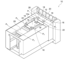
- 1 is a perspective view schematically showing an example of a metal foil cutting and stacking device according to the present invention.
- FIG. 3 is a sectional view taken along line P 2 -P 2 for explaining a state in which the metal foil is held between the chuck mechanisms in the metal foil cutting and loading device shown in FIG. 2;
- the method of cutting and stacking metal foil according to the present invention includes (a) unwinding of metal foil, (b) clamping of metal foil by a chuck mechanism, (c) cutting of metal foil, (d) conveyance of metal foil pieces, (e) ) loading the metal foil pieces by releasing them from the chuck mechanism; and (f) moving the chuck mechanism.
- Each step from (a) to (f) is then automatically performed and repeated by at least one device.
- the metal foil is cut and transported while being held by the chuck mechanism, and the metal foil pieces are released from the chuck mechanism at the loading position, thereby completing a series of operations from cutting the metal foil to loading.
- FIGS. 1A and 1B conceptually show a series of steps in the method for cutting and stacking metal foil according to the present invention.
- FIG. 2 shows a metal foil cutting and stacking device 10 used in such a metal foil cutting and stacking method.
- the metal foil cutting and loading device 10 includes a supply roll 14, a pedestal 16, a chuck mechanism 18, a cutter 20, a loading section 22, a moving mechanism 24, and a control section (not shown).
- FIGS. 1A and 1B are depicted as having different positions and orientations of members from the metal foil cutting and loading apparatus 10 according to the specific form shown in FIG. 2.
- each process from steps (a) to (f) and each component of the metal foil cutting and loading device 10 will be explained with reference to these figures.
- each step (a) to (f) is automatically performed and repeated by at least one device.
- the metal foil 12 is unrolled onto the base 16 from the metal foil roll (step (a)).
- the metal foil 12 may be unwound from the metal foil roll by rotating the supply roll 14.
- the pedestal 16 is not particularly limited as long as it is a structure such as a stage that has a flat surface on which the unwound metal foil 12 is placed.
- pedestal 16 is made of metal. If the pedestal 16 is made of metal, static electricity is less likely to be generated (or the generated static electricity can be released), so it is possible to avoid the metal foil 12 from sticking to the pedestal 16 due to static electricity, and the subsequent process (b) ) to (e) can be performed more smoothly. In addition, suppressing the generation of static electricity also leads to a reduction in displacement of the metal foil pieces 12a when the metal foil pieces 12a are loaded.
- the material of the metal foil 12 is not particularly limited.
- Examples of the metal foil 12 include aluminum foil, copper foil, stainless steel foil, nickel foil, etc., and preferably copper foil.
- the copper foil may be either rolled copper foil or electrolytic copper foil.
- step (b) Clamping of the metal foil by the chuck mechanism
- a part of the unwound metal foil 12 (for example, the end in the width direction) is held at the first position P1 by the chuck mechanism 18.
- step (b) By clamping the metal foil 12 before cutting, the metal foil 12 or the metal foil piece 12a can be clamped at the same position each time, which leads to prevention of misalignment.
- the chuck mechanism 18 is not particularly limited as long as it can hold the unwound metal foil 12 at the first position P1 , and any known configuration may be adopted.
- the chuck mechanism 18 includes a pair of plate-like members that sandwich the metal foil 12 from above and below, and a movable part that moves the pair of plate-like members so that the metal foil 12 can be held and released.
- the surface of the portion of the chuck mechanism 18 that clamps the metal foil 12 is preferably made of a material that has elasticity and is less likely to cause electrostatic damage because the surface of the metal foil 12 is less likely to be scratched.
- Preferred examples of such materials include resins, fibers, and the like.
- Preferred examples of the resin include urethane rubber, silicone resin, etc., and preferred examples of the fiber include felt.
- the first position P1 is located on the downstream side of the cutter 20 with respect to the unwinding direction of the metal foil 12, so that the chuck mechanism 18 holds the metal foil 12 during cutting, and also holds the metal foil 12 after cutting.
- the metal foil piece 12a can be conveyed to the stacking section 22 while being held. From this point of view, as shown in FIGS. 2 and 3, it is preferable that the metal foil piece 12a be held in at least two places by the chuck mechanism 18, since the metal foil piece 12a can be held stably. More preferably, as shown in FIG. 2, at least two locations are located on two mutually parallel sides constituting the outer periphery of the metal foil 12, and the two mutually parallel sides are aligned with the moving direction M of the chuck mechanism 18. parallel.
- a space is provided for holding the metal foil by the chuck mechanism 18.
- a slit notch
- Step (c) Cutting the metal foil As shown in FIG. 1A (iii), the metal foil 12 is cut on the pedestal 16 while being held by the chuck mechanism 18 to obtain individualized metal foil pieces 12a. (Step (c)). By doing so, the position of the metal foil 12 is fixed by the chuck mechanism 18, so that the displacement of the metal foil pieces 12a during loading can be reduced. Furthermore, it becomes possible to cut the metal foil 12 at an accurate position determined each time.
- the metal foil 12 may be cut with the metal foil 12 in contact with the pedestal 16, or a part or all of the metal foil 12 may be cut by blowing air toward the lower surface of the metal foil 12 from the opening of the pedestal 16. You may perform this while floating from the pedestal 16. By bringing the metal foil 12 into contact with the pedestal 16, continuous and stable cutting can be performed. On the other hand, by floating the metal foil 12, it is possible to suppress the generation of static electricity during cutting and reduce positional deviation when forming the metal foil pieces 12a.
- the cutter 20 is not particularly limited as long as it can cut the metal foil 12 on the pedestal 16 into individual metal foil pieces 12a.
- Examples of the cutter 20 include a rotary cutter, a guillotine cutter, and the like.
- a cutter of a type that presses the metal foil 12 against the base 16 with one blade may be used, or a cutter of a type that cuts the metal foil 12 from above and below with two blades, an upper blade and a lower blade.
- a cutter with two blades, an upper blade and a lower blade by providing a slit in the pedestal 16 so that the lower blade can contact the metal foil 12 from below the slit, the metal foil 12 can be contacted from above.
- the structure may be such that the metal foil 12 is sandwiched together with the upper blade.
- the size of the metal foil piece 12a is not particularly limited, but is preferably from 200 mm x 200 mm to 1500 mm x 1500 mm, more preferably from 300 mm x 300 mm to 1000 mm x 1000 mm, and most preferably from 400 mm x 400 mm to 700 mm x 700 mm. .
- step (d) Conveying the metal foil piece As shown in FIG. 1B(iv), by moving the chuck mechanism 18 to the second position P2 , the metal foil piece 12a held by the chuck mechanism 18 is removed from the base 16. It is transported to a distant loading section 22 (step (d)). Since the metal foil piece 12a is conveyed while being held by the chuck mechanism 18, additional steps such as suction of the metal foil piece 12a (as disclosed in Patent Document 2) are not necessary, so the takt time can be shortened. can. In addition, the metal foil pieces 12a can be conveyed without being misaligned by being held by the chuck mechanism 18, and as a result, misalignment of the metal foil pieces 12a during loading in the subsequent step (e) can be reduced.
- the loading section 22 is not particularly limited as long as it provides a place for the metal foil pieces 12a to be stacked, but preferably has a flat surface so that the metal foil pieces 12a can be stacked flatly. .
- the second position P2 is a position corresponding to the loading section 22, so that when the chuck mechanism 18 releases the metal foil piece 12a in the subsequent step (e), the second position P2 is a position corresponding to the loading section 22.
- the metal foil pieces 12a can be stacked accurately without positional deviation.
- the moving direction M of the chuck mechanism 18 that is, the conveyance direction of the metal foil piece 12a
- the second position P 2 is a position moved from the first position P 1 by a predetermined distance in the unwinding direction (downstream direction) of the metal foil 12 . In this case, it is desirable that the distance between the first position P1 and the second position P2 be longer than the length of the metal foil piece 12a.
- Movement of the chuck mechanism 18 is performed by a moving mechanism 24.
- the moving mechanism 24 is not particularly limited as long as it is a mechanism for reciprocating the chuck mechanism 18 between the first position P1 and the second position P2 .
- the moving mechanism 24 preferably includes a rail and a motor for driving the chuck mechanism 18 that is provided so as to be slidable along the rail.
- the rails are provided parallel to the unwinding direction of the metal foil 12. More preferably, one rail is provided on each side of the metal foil piece 12a in the width direction (i.e., two rails in total) so that the chuck mechanism 18 can move while holding both ends of the metal foil piece 12a in the width direction. Preferably, it is provided.
- the metal foil cutting and loading device 10 further includes an air injector for blowing air toward the lower surface of the metal foil piece 12a.
- the base 16 has an opening and that the air injector is arranged below the opening of the base 16.
- the metal foil cutting and stacking device 10 further includes a pressing member 26 disposed above the stacking section 22 for pressing down a part of the metal foil piece 12a.
- the metal foil cutting and loading device 10 may be provided with a disposal section 28 separately from the loading section 22.
- the cut metal foil pieces 12a are visually inspected or checked for defects such as scratches or folds using an inspection means such as a sensor, and the moving mechanism 24 loads metal foil pieces 12a that are determined to be defective.
- the metal foil piece 12a is released by transporting it to a third position P3 corresponding to the waste section 28 (for example, passing through the loading section 22) instead of the section 22.
- the operation of the moving mechanism 24 in this case is the same as the operation in the loading section 22, except that it moves to the third position P3 instead of the second position P2 (and then returns to the first position P1 ).
- the operation of the chuck mechanism 18 to release the metal foil piece 12a can also be the same as the operation in the loading section 22.
- step (e) Loading of the metal foil piece by releasing it from the chuck mechanism As shown in FIG . are loaded on the loading section 22 (step (e)).
- the metal foil piece 12a When the metal foil piece 12a is released from the chuck mechanism 18, it naturally falls to a desired position and is placed on the surface of the loading section 22 or on the metal foil piece 12a that has already been loaded. Therefore, the metal foil pieces 12a can be stacked without rubbing against the surface of the stacking section 22 or the metal foil pieces 12a that are already loaded, making it difficult for the metal foil pieces 12a to be scratched.
- the metal foil pieces 12a can be loaded at the second position P2 , which is accurately positioned by the chuck mechanism 18. If necessary, a positioning guide may be provided at the end of the loading section 22 as appropriate.
- the metal foil pieces 12a can be stacked at more accurate positions.
- it is not necessary to provide a positioning guide and in that case, damage caused by contact between the metal foil piece 12a and the positioning guide can be reduced. Therefore, an appropriate mode may be selected depending on the quality requirements for the metal foil actually handled.
- This loading method contributes to reducing displacement of the metal foil pieces 12a during loading and to reducing scratches on the metal foil pieces 12a.
- step (f) Movement of the chuck mechanism
- the chuck mechanism 18 is moved back to the first position P1 (step (f)).
- FIG. 1B(vii) which is the same diagram as FIG. 1A(i)
- a desired number of metal foil pieces 12a can be sequentially stacked on the stacking section 22.
- the metal foil roll can be processed into a stack of a plurality of metal foil pieces 12a suitable for shipping.
- each step from steps (a) to (f) is automatically performed and repeated by at least one device.
- the metal foil cutting and loading device 10 is equipped with a control section (not shown).
- the control unit controls the supply roll 14, the chuck mechanism 18, the cutter 20, the moving mechanism 24, and the presser (if any) so as to automatically perform the operations of each step from steps (a) to (f).
- Control member 26 Therefore, there may be multiple controllers. For example, after cutting the metal foil 12 in step (c), at the timing when the upper blade of the cutter 20 returns to its original position, the control unit issues a cutting end signal, and upon receiving this signal, the moving mechanism 24 starts conveying. It is sufficient if the configuration is such that
- the metal foil cutting and loading device 10 includes an operation panel and/or a touch panel panel, and can be configured to allow operation, instruction, and monitoring by an operator.
- the operator can press a predetermined button to transfer the metal foil piece 12a to the moving mechanism 24 (
- a configuration may also be adopted in which an instruction is issued via the control unit to transport to the disposal unit 28 (instead of the loading unit 22).
Landscapes
- Life Sciences & Earth Sciences (AREA)
- Forests & Forestry (AREA)
- Engineering & Computer Science (AREA)
- Mechanical Engineering (AREA)
- Fixed Capacitors And Capacitor Manufacturing Machines (AREA)
- Advancing Webs (AREA)
- Details Of Cutting Devices (AREA)
- Metal Rolling (AREA)
- Delivering By Means Of Belts And Rollers (AREA)
- Collation Of Sheets And Webs (AREA)
Priority Applications (5)
| Application Number | Priority Date | Filing Date | Title |
|---|---|---|---|
| CN202280093317.7A CN118843534A (zh) | 2022-03-18 | 2022-03-18 | 金属箔的切断堆叠方法及金属箔切断堆叠装置 |
| JP2024507427A JP7837396B2 (ja) | 2022-03-18 | 2022-03-18 | 金属箔の切断積載方法及び金属箔切断積載装置 |
| PCT/JP2022/012682 WO2023175925A1 (ja) | 2022-03-18 | 2022-03-18 | 金属箔の切断積載方法及び金属箔切断積載装置 |
| TW114117670A TW202533931A (zh) | 2022-03-18 | 2023-03-17 | 金屬箔之切斷裝載方法及金屬箔切斷裝載裝置 |
| TW112109981A TWI892098B (zh) | 2022-03-18 | 2023-03-17 | 金屬箔之切斷裝載方法及金屬箔切斷裝載裝置 |
Applications Claiming Priority (1)
| Application Number | Priority Date | Filing Date | Title |
|---|---|---|---|
| PCT/JP2022/012682 WO2023175925A1 (ja) | 2022-03-18 | 2022-03-18 | 金属箔の切断積載方法及び金属箔切断積載装置 |
Publications (1)
| Publication Number | Publication Date |
|---|---|
| WO2023175925A1 true WO2023175925A1 (ja) | 2023-09-21 |
Family
ID=88023010
Family Applications (1)
| Application Number | Title | Priority Date | Filing Date |
|---|---|---|---|
| PCT/JP2022/012682 Ceased WO2023175925A1 (ja) | 2022-03-18 | 2022-03-18 | 金属箔の切断積載方法及び金属箔切断積載装置 |
Country Status (4)
| Country | Link |
|---|---|
| JP (1) | JP7837396B2 (https=) |
| CN (1) | CN118843534A (https=) |
| TW (2) | TWI892098B (https=) |
| WO (1) | WO2023175925A1 (https=) |
Citations (7)
| Publication number | Priority date | Publication date | Assignee | Title |
|---|---|---|---|---|
| JPS4726461Y1 (https=) * | 1967-08-29 | 1972-08-15 | ||
| JPS5286181U (https=) * | 1975-12-23 | 1977-06-27 | ||
| JPS6020900A (ja) * | 1983-07-15 | 1985-02-02 | 松下電工株式会社 | 金属箔シ−トの搬送積載装置 |
| JPH0269995U (https=) * | 1988-11-11 | 1990-05-28 | ||
| JPH07237798A (ja) * | 1994-02-25 | 1995-09-12 | N C Ee:Kk | シート状物引出し装置 |
| JP2003001591A (ja) * | 2001-06-21 | 2003-01-08 | Shinko Electric Co Ltd | 金属箔切断装置 |
| JP2007022733A (ja) * | 2005-07-14 | 2007-02-01 | Inoac Corp | シート積載装置 |
-
2022
- 2022-03-18 CN CN202280093317.7A patent/CN118843534A/zh active Pending
- 2022-03-18 JP JP2024507427A patent/JP7837396B2/ja active Active
- 2022-03-18 WO PCT/JP2022/012682 patent/WO2023175925A1/ja not_active Ceased
-
2023
- 2023-03-17 TW TW112109981A patent/TWI892098B/zh active
- 2023-03-17 TW TW114117670A patent/TW202533931A/zh unknown
Patent Citations (7)
| Publication number | Priority date | Publication date | Assignee | Title |
|---|---|---|---|---|
| JPS4726461Y1 (https=) * | 1967-08-29 | 1972-08-15 | ||
| JPS5286181U (https=) * | 1975-12-23 | 1977-06-27 | ||
| JPS6020900A (ja) * | 1983-07-15 | 1985-02-02 | 松下電工株式会社 | 金属箔シ−トの搬送積載装置 |
| JPH0269995U (https=) * | 1988-11-11 | 1990-05-28 | ||
| JPH07237798A (ja) * | 1994-02-25 | 1995-09-12 | N C Ee:Kk | シート状物引出し装置 |
| JP2003001591A (ja) * | 2001-06-21 | 2003-01-08 | Shinko Electric Co Ltd | 金属箔切断装置 |
| JP2007022733A (ja) * | 2005-07-14 | 2007-02-01 | Inoac Corp | シート積載装置 |
Also Published As
| Publication number | Publication date |
|---|---|
| CN118843534A (zh) | 2024-10-25 |
| TWI892098B (zh) | 2025-08-01 |
| TW202533931A (zh) | 2025-09-01 |
| JPWO2023175925A1 (https=) | 2023-09-21 |
| TW202400389A (zh) | 2024-01-01 |
| JP7837396B2 (ja) | 2026-03-30 |
Similar Documents
| Publication | Publication Date | Title |
|---|---|---|
| US20080168876A1 (en) | Device for supporting plate-shaped materials | |
| JP5518639B2 (ja) | 変圧器鉄心の製造装置および製造方法 | |
| KR102186952B1 (ko) | 메탈필름롤 재단시스템 | |
| JP5146903B2 (ja) | ガラス基板梱包装置 | |
| TWI500528B (zh) | 用於打印機的箔片引導裝置 | |
| JP6353652B2 (ja) | 打ち抜き切断装置 | |
| CN100577542C (zh) | 超长薄膜的运送装置和运送方法 | |
| US11352218B2 (en) | Multi-conveyor belt based insertion mechanism for pocketed coil springs | |
| WO2023175925A1 (ja) | 金属箔の切断積載方法及び金属箔切断積載装置 | |
| CN113474136A (zh) | 保护片切断装置及玻璃基板捆包体的制造方法 | |
| WO2020126450A1 (en) | Magnetic lift platform for transfer of coil springs | |
| WO2016199447A1 (ja) | 帯状板の接合方法 | |
| JP6284117B2 (ja) | 巻掛け梱包装置 | |
| US6872044B2 (en) | Apparatus for and method of manufacturing sheets | |
| KR102226078B1 (ko) | 금속 다공체 제조용 물류 반송 장치 | |
| WO2022219871A1 (ja) | ガラス板梱包体の製造方法及びガラス板梱包体 | |
| CN111989220B (zh) | 压印箔的驱动装置,压印站和压印机及控制压印箔的驱动的方法 | |
| JPH06206201A (ja) | ランニングソーシステム | |
| JP7130244B2 (ja) | 積層コア形成用の積層材製造装置 | |
| EP3782821B1 (en) | Paper stack press machine | |
| JPH01210298A (ja) | シート束の切断方法および装置 | |
| CN114641382B (zh) | 工件加工装置 | |
| CN120755928A (zh) | 贴胶压v组成型结构 | |
| JPH0852575A (ja) | 熱切断加工機のワーク搬送装置 | |
| JP2707386B2 (ja) | シート束搬送装置 |
Legal Events
| Date | Code | Title | Description |
|---|---|---|---|
| 121 | Ep: the epo has been informed by wipo that ep was designated in this application |
Ref document number: 22932197 Country of ref document: EP Kind code of ref document: A1 |
|
| ENP | Entry into the national phase |
Ref document number: 2024507427 Country of ref document: JP Kind code of ref document: A |
|
| WWE | Wipo information: entry into national phase |
Ref document number: 202280093317.7 Country of ref document: CN |
|
| NENP | Non-entry into the national phase |
Ref country code: DE |
|
| 122 | Ep: pct application non-entry in european phase |
Ref document number: 22932197 Country of ref document: EP Kind code of ref document: A1 |