WO2023175900A1 - ヒートポンプ熱源機 - Google Patents
ヒートポンプ熱源機 Download PDFInfo
- Publication number
- WO2023175900A1 WO2023175900A1 PCT/JP2022/012622 JP2022012622W WO2023175900A1 WO 2023175900 A1 WO2023175900 A1 WO 2023175900A1 JP 2022012622 W JP2022012622 W JP 2022012622W WO 2023175900 A1 WO2023175900 A1 WO 2023175900A1
- Authority
- WO
- WIPO (PCT)
- Prior art keywords
- box
- transformer
- water pump
- source device
- heat source
- Prior art date
- Legal status (The legal status is an assumption and is not a legal conclusion. Google has not performed a legal analysis and makes no representation as to the accuracy of the status listed.)
- Ceased
Links
Images






Classifications
-
- H—ELECTRICITY
- H05—ELECTRIC TECHNIQUES NOT OTHERWISE PROVIDED FOR
- H05K—PRINTED CIRCUITS; CASINGS OR CONSTRUCTIONAL DETAILS OF ELECTRIC APPARATUS; MANUFACTURE OF ASSEMBLAGES OF ELECTRICAL COMPONENTS
- H05K7/00—Constructional details common to different types of electric apparatus
- H05K7/20—Modifications to facilitate cooling, ventilating, or heating
- H05K7/20218—Modifications to facilitate cooling, ventilating, or heating using a liquid coolant without phase change in electronic enclosures
- H05K7/20272—Accessories for moving fluid, for expanding fluid, for connecting fluid conduits, for distributing fluid, for removing gas or for preventing leakage, e.g. pumps, tanks or manifolds
-
- F—MECHANICAL ENGINEERING; LIGHTING; HEATING; WEAPONS; BLASTING
- F24—HEATING; RANGES; VENTILATING
- F24F—AIR-CONDITIONING; AIR-HUMIDIFICATION; VENTILATION; USE OF AIR CURRENTS FOR SCREENING
- F24F11/00—Control or safety arrangements
- F24F11/88—Electrical aspects, e.g. circuits
-
- F—MECHANICAL ENGINEERING; LIGHTING; HEATING; WEAPONS; BLASTING
- F24—HEATING; RANGES; VENTILATING
- F24F—AIR-CONDITIONING; AIR-HUMIDIFICATION; VENTILATION; USE OF AIR CURRENTS FOR SCREENING
- F24F1/00—Room units for air-conditioning, e.g. separate or self-contained units or units receiving primary air from a central station
- F24F1/06—Separate outdoor units, e.g. outdoor unit to be linked to a separate room comprising a compressor and a heat exchanger
- F24F1/20—Electric components for separate outdoor units
- F24F1/22—Arrangement or mounting thereof
-
- F—MECHANICAL ENGINEERING; LIGHTING; HEATING; WEAPONS; BLASTING
- F25—REFRIGERATION OR COOLING; COMBINED HEATING AND REFRIGERATION SYSTEMS; HEAT PUMP SYSTEMS; MANUFACTURE OR STORAGE OF ICE; LIQUEFACTION SOLIDIFICATION OF GASES
- F25B—REFRIGERATION MACHINES, PLANTS OR SYSTEMS; COMBINED HEATING AND REFRIGERATION SYSTEMS; HEAT PUMP SYSTEMS
- F25B30/00—Heat pumps
- F25B30/02—Heat pumps of the compression type
Definitions
- the present disclosure relates to a heat pump heat source device used in devices that heat or cool water, such as chillers and water heaters.
- the transformer is housed in a box and installed in the housing of the heat source device along with the compressor, heat exchanger, control device, etc. .
- a transformer is housed in a storage box, and the storage box and a control device are installed on the bottom plate of an outdoor unit that is a heat source device.
- the storage box when electrical components such as a transformer and a reactor are housed in a storage box, the storage box is placed on the bottom plate of the heat source device casing from the viewpoint of maintainability and balance of the center of gravity of the casing. It may be installed. Furthermore, some heat pump type chillers and water heaters have a water pump disposed within the housing of the heat source device. That is, a storage box that stores electronic components such as a transformer may be housed together with a water pump in one housing. However, if the storage box and control device are installed on the bottom plate of the heat source device, there is a risk that the electronic components and control device inside the storage box may be submerged or submerged in water if water leaks from the water pump inside the heat source device housing. There was an issue that there was.
- the present disclosure has been made to solve the above-mentioned problems, and provides a heat pump that can prevent a transformer and a control device from being submerged or submerged in water when water leaks in the housing of a heat pump heat source device.
- the purpose is to provide heat source equipment.
- a heat pump heat source device includes a casing having a bottom plate, a water pump box provided on the front side of the bottom plate for storing a water pump, and a transformer box provided above the water pump box for storing a transformer.
- the transformer box includes a transformer box and a control device box provided above the transformer box that stores a control device.
- the water pump box that houses the water pump is provided on the bottom plate of the casing of the heat source device. Further, a transformer box that houses the transformer is provided above the water pump box. Further, a control device box housing the control device is provided above the transformer box. Because the transformer and control device are installed above the water pump box rather than on the bottom plate of the heat source device's case, if water leaks inside the heat source device's case, the control device and transformer will be submerged or flooded. is avoided.
- FIG. 1 is a circuit diagram showing the configuration of a heat pump heat source device according to an embodiment.
- FIG. 1 is a perspective view showing the internal configuration of a heat pump heat source device according to an embodiment.
- FIG. 2 is a perspective view showing an installation configuration of a water pump box, a transformer box, and a control device box according to an embodiment. It is an exploded perspective view explaining composition of a water pump box and a transformer box concerning an embodiment. It is a figure for explaining the removal procedure of a transformer box. It is a perspective view explaining arrangement of a plurality of transformers concerning an embodiment.
- FIG. 2 is a perspective view showing the internal configuration of a transformer box according to an embodiment.
- FIG. 8 is a plan view of the transformer box in the state shown in FIG. 7; FIG.
- FIG. 8 is a front view of the transformer box in the state shown in FIG. 7;
- FIG. 8 is a side perspective view of the transformer box in the state of FIG. 7; It is a top view showing the bundling of the wiring in the transformer box concerning an embodiment. It is a front view showing the bundling of the wiring in the transformer box concerning an embodiment.
- the X direction indicates the left-right direction of the heat pump heat source device, and the arrow indicates the direction from right to left.
- the Y direction indicates the front-rear direction of the heat pump heat source device, and the arrow indicates the direction from the front to the rear.
- the Z direction indicates the vertical direction of the heat pump heat source device, and the arrow indicates the direction from the bottom to the top.
- FIG. 1 is a circuit diagram showing the configuration of a heat pump heat source device 100 according to an embodiment.
- the heat pump heat source device 100 includes a compressor 210, a load side heat exchanger 220, a throttle device 230, a heat source side heat exchanger 240, a refrigerant pipe 260, a water pipe 270, a water pump 5, and a control device 1. and a transformer 3.
- a configuration in which a heat pump heat source device 100 is used in a heat pump water heater 200 will be described.
- the heat pump heat source device 100 is a heat pump in which a compressor 210, a load-side heat exchanger 220, a throttle device 230, and a heat source-side heat exchanger 240 are connected in an annular manner via a refrigerant pipe 260, and a refrigerant such as carbon dioxide circulates. Configure the circuit. Further, in the heat pump heat source device 100, the load-side heat exchanger 220 and the water pump 5 are connected to a hot water storage tank 250 in an annular manner via a water pipe 270, forming a water circuit through which water passes.
- the heat pump water heater 200 includes a heat pump circuit and a water circuit, and the heat pump heat source device 100 is a part of the heat pump water heater 200.
- the compressor 210 sucks and compresses a low-temperature and low-pressure gas refrigerant, and discharges the gas refrigerant in a high-temperature and high-pressure state.
- the load-side heat exchanger 220 is a heat exchanger that functions as a condenser.
- the load-side heat exchanger 220 exchanges heat between the refrigerant and the water passing through the water circuit. Specifically, heat is radiated from the refrigerant and water is heated.
- the expansion device 230 reduces the pressure of the high-pressure refrigerant and adjusts the pressure and flow rate of the refrigerant.
- the heat source side heat exchanger 240 exchanges heat between the refrigerant passing through the heat source side heat exchanger 240 and air.
- the heat source side heat exchanger 240 is a heat exchanger that functions as an evaporator. In the heat source side heat exchanger 240, the refrigerant exchanges heat with, for example, outdoor air.
- the load-side heat exchanger 220, the hot water storage tank 250, and the water pump 5 are connected in an annular manner by a water pipe 270.
- Water for hot water supply circulates through the water circuit.
- Water for hot water supply is stored in the hot water storage tank 250.
- the water pump 5 pressurizes water for hot water supply and circulates it within the water circuit.
- the cold and hot water in the lower part of the hot water storage tank 250 is conveyed to the load-side heat exchanger 220 by the water pump 5.
- the heat pump heat source device 100 is used in the heat pump water heater 200.
- the heat pump heat source device 100 is used to heat and cool water, and may be used as part of a heat pump chiller.
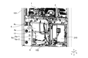
- FIG. 2 is a perspective view showing the internal configuration of the heat pump heat source device 100 according to the embodiment.
- the heat pump heat source device 100 includes a compressor 210, a control device 1, a control device box 2, a transformer 3, and a transformer inside a rectangular housing 101 forming an outer shell. It includes a box 4, a water pump 5, and a water pump box 6.
- One of the plates forming the side surface of the housing 101 is configured to be removable, and FIG. 2 shows a state in which this plate is removed.
- the front surface In the casing 101 of the heat pump heat source device 100, the surface on which the removable plate is provided is referred to as the front surface.
- the front side of the housing 101 of the heat pump heat source device 100 refers to the front side or the front side where a removable plate is provided.
- the control device 1 has a microcomputer equipped with a CPU, ROM, RAM, I/O port, etc., and controls the compressor 210, for example.
- the control device 1 is housed in a control device box 2.
- the transformer 3 is provided inside the heat pump heat source device 100 and converts voltage. The current whose voltage has been converted by the transformer 3 is used, for example, to drive the compressor 210.
- the transformer 3 is housed in a transformer box 4.
- the water pump 5 circulates water in a water circuit constituted by the load-side heat exchanger 220.
- the water pump 5 is housed in a water pump box 6.
- a water pump box 6 containing the water pump 5 is provided on the bottom plate 102 of the housing 101.
- a compressor 210 is provided on the bottom plate 102 of the housing 101 in parallel with the water pump box 6.
- a transformer box 4 housing a transformer 3 is provided above the water pump box 6.
- a control device box 2 containing a control device 1 is provided above the transformer box 4.
- the water pump box 6, transformer box 4, and control device box 2 do not overlap each other in the front-back direction. Further, the water pump box 6 and the control device box 2 are provided on the front side inside the casing 101 of the heat pump heat source device 100.
- the total value of the height of the transformer box 4 and the height of the water pump box 6 is defined as the height h1. Further, the height from the bottom plate 102 to the lower end of the control device box 2 is defined as a height h2. At this time, the height h1 and the height h2 have a relationship of h1>h2.
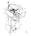
- FIG. 3 is a perspective view showing the installation configuration of the water pump box 6, transformer box 4, and control device box 2 according to the first embodiment.
- the water pump box 6 has a front panel 6a that covers the front surface.
- the front panel 6a includes a first front panel 6a-1 and a second front panel 6a-2.
- a transformer box 4 is provided above the water pump box 6 so that it at least partially overlaps when viewed in the vertical direction.
- a pedestal 11 is provided between the water pump box 6 and the transformer box 4. The pedestal 11 corresponds to a ceiling that covers the upper surface of the water pump box 6.
- a transformer box 4 is provided on the pedestal 11.
- the transformer box 4 has a front panel 4a that covers the front surface of the transformer box 4, and a top panel 4c that covers the top surface of the transformer box 4. Details of the water pump box 6, transformer box 4, and pedestal 11 will be described later.
- a control device box 2 is provided above the transformer box 4 so that it at least partially overlaps when viewed in the vertical direction. As shown in FIG. 3, another device may be provided between the transformer box 4 and the control device box 2. Although not shown, the control device box 2 may be provided on the top panel 4c of the transformer box 4.
- FIG. 4 is an exploded perspective view illustrating the configurations of the water pump box 6 and transformer box 4 according to the first embodiment.
- illustration of the water pump 5 is omitted.
- the water pump box 6 includes a side back panel 6b and a bottom panel 6d in addition to the first front panel 6a-1 and second front panel 6a-2 described above.
- the side and rear panels 6b of the water pump box 6 constitute the left and right side surfaces and the back surface of the water pump box 6.
- the bottom panel 6d constitutes the bottom surface of the water pump box 6.
- the water pump 5 is provided on the bottom panel 6d. As shown in FIG. 4, an opening may be provided in the side rear panel 6b so that a water pipe (not shown) can be connected to the water pump 5 housed in the water pump box 6.
- a first front panel 6a-1 and a second front panel 6a-2 provided above the first front panel 6a-1 are provided on the front surface of the water pump box 6.
- the first front panel 6a-1 covers at least the upper half of the front surface of the water pump box 6.
- the second front panel 6a-2 covers at least a quarter of the front surface of the water pump box 6 from the bottom.
- the first front panel 6a-1 and the second front panel 6a-2 can be individually attached to and detached from the side rear panel 6b. Since the first front panel 6a-1 and the second front panel 6a-2 can be attached and detached separately, only those necessary for maintenance such as inspection, maintenance, or repair need to be attached and detached.
- work such as inspection, maintenance, or repair may be referred to as maintenance.
- the first front panel 6a can be installed without removing these other components.
- Maintenance of the water pump 5 may be performed by removing either the front panel -1 or the second front panel 6a-2.
- the components may be arranged in front of the front panel 6a of the water pump box 6.
- an example is shown in which two panels, the first front panel 6a-1 and the second front panel 6a-2, are provided on the front surface of the water pump box 6. Three or more panels may be provided on the front.
- a pedestal 11 is provided between the water pump box 6 and the transformer box 4.
- the pedestal 11 functions as a top panel of the water pump box 6.
- the transformer box 4 is provided on a pedestal 11. Since the transformer box 4 is provided on the pedestal 11, the length of the pedestal 11 in the left and right direction is either the same as the length of the transformer box 4 in the left and right direction, or is longer than the length of the transformer box 4 in the left and right direction. long. In FIG. 4, the length of the transformer box 4 in the left-right direction is longer than the length of the water pump box 6 in the left-right direction. Therefore, the length of the pedestal 11 in the left-right direction is longer than the length of the water pump box 6 in the left-right direction.
- a part of the pedestal 11 protrudes from the water pump box 6.
- the end portion of the pedestal 11 protruding from the water pump box 6 is supported by the support legs 7.
- a portion of the frame 11 that does not protrude from the water pump box 6 is supported by the water pump box 6.
- the support legs 7 are provided on the bottom plate 102 of the housing 101.
- the height of the support legs 7 is the same as the height of the water pump box 6.
- the support leg 7 has a surface extending in the front-rear direction of the heat pump heat source device 100, and supports the lower surface of the pedestal 11 in the front-rear direction.
- the support legs 7 in FIG. 4 have a rectangular tray shape, and support the pedestal 11 in an upright state. Note that a plurality of support legs 7 may be provided.
- the length of the pedestal 11 in the left and right direction may be increased, regardless of the length of the transformer box 4 in the left and right direction.
- the length of the portion of the pedestal 11 that protrudes from the water pump box 6 in the left-right direction becomes longer. Therefore, the distance between the support legs 7 supporting the ends of the pedestal 11 and the water pump box 6 also becomes longer. Therefore, a space is formed between the support leg 7 and the water pump box 6.
- This space can be used when performing work such as inspection, maintenance, or repair of the water pump 5. For example, when replacing parts such as heat insulation covers, antifreeze heaters, and thermistors attached to piping connected to the water pump 5, the space between the support legs 7 and the water pump box 6 can be used as a work area. It can be used as
- the length of the transformer box 4 in the left-right direction is shorter than the length of the water pump box 6 in the left-right direction
- the length of the pedestal 11 in the left-right direction is equal to the length of the water pump box 6 in the left-right direction. It should be the same as the length.
- the support legs 7 may not be provided.
- a transformer box 4 is provided on the pedestal 11.
- the transformer box 4 includes side and rear panels 4b, a bottom panel 4d, and legs 4e.
- the front panel 4a and the top panel 4c of the transformer box 4 can be individually attached to and removed from the side rear panel 4b of the transformer box 4, as shown in FIG. Therefore, even if components such as power wiring and piping are arranged in front of the front panel 4a of the transformer box 4 and it is difficult to remove the front panel 4a, the top panel 4c can be attached and detached. Thereby, the inside of the transformer box 4 can be checked during maintenance. Therefore, even if components such as power supply wiring and piping are arranged in front of the front panel 4a of the transformer box 4, maintenance of the transformer 3 can be easily performed.
- the side and rear panels 4b of the transformer box 4 constitute the left and right side surfaces and the rear surface of the transformer box 4.
- the bottom panel 4d constitutes the bottom surface of the transformer box 4.
- the transformer 3 is screwed and fixed onto the bottom panel 4d.
- three transformers 3 are housed in the transformer box 4 side by side in the left-right direction.
- a fuse 8, a fuse box 9, and a fuse stand 10 are housed inside the transformer box 4, in addition to the three transformers 3, a fuse 8, a fuse box 9, and a fuse stand 10 are housed. Details of the three transformers 3, fuse 8, fuse box 9, and fuse stand 10 will be described later.
- the bottom panel 4d of the transformer box 4 is supported by two legs 4e.
- the left end and the right end of the bottom panel 4d are supported by the legs 4e, respectively.
- Each of the leg portions 4e has a surface extending in the front-rear direction of the heat pump heat source device 100, and supports the lower surface of the bottom panel 4d in the front-rear direction.
- the right leg 4e is illustrated, but the left leg 4e is not illustrated.
- the bottom panel 4d is supported by the legs 4e, a space is formed between the pedestal 11 and the bottom panel 4d.
- the front panel 4a of the transformer box 4 covers the space between the pedestal 11 and the top panel 4c of the transformer box 4. Therefore, as shown in FIG. 3, the space between the pedestal 11 and the bottom panel 4d of the transformer box 4 cannot be visually observed.
- a part of the leg part 4e of the transformer box 4 and a part of the side back panel 4b are fixed to the pedestal 11 in an overlapping state.
- the legs 4e and the side back panel 4b may be fixed on the pedestal 11 with a common screw.
- screw holes are provided in each of the pedestal 11, the leg portions 4e, and the side and back panels 4b.
- the screw holes of the leg portion 4e are overlapped with the screw holes of the pedestal 11, and the screw holes of the side back panel 4b are overlapped with the screw holes of the leg portion 4e.
- the leg portions 4e and the side and back panels 4b are fixed to the pedestal 11 by screwing them from above the screw holes in the side and back panels 4b. As a result, the transformer box 4 is fixed to the pedestal 11.
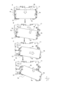
- FIG. 5 is a diagram for explaining the procedure for removing the transformer box 4.
- FIG. 5 shows a top view of the transformer box 4.
- the white arrow in FIG. 5 indicates the direction in which the transformer box 4 is moved.
- FIG. 5 shows an example in which the panel 12 is arranged on the front left side of the transformer box 4.
- the panel 12 is provided, for example, so as to cover at least a portion of the left front surface of the transformer box 4.
- the transformer box 4 is screwed to the pedestal 11, first remove all the screws fixing the transformer box 4 to the pedestal 11. Then, with the transformer box 4 not screwed to the pedestal 11, the transformer box 4 is pulled out to the front as shown in A of FIG. Next, as shown in B, rotate the transformer box 4 slightly clockwise and pull it out to the front. Next, the transformer box 4 is shifted to the right side as shown in C in order to avoid the panel 12 located on the left front side. Then, as shown in D, the transformer box 4 is pulled out to the front while being rotated clockwise little by little. In addition, in FIG. 5, since the panel 12 is arranged on the left front side of the transformer box 4, an example is shown in which the transformer box 4 is rotated clockwise and pulled out to the front side. When the panel 12 is arranged on the right front side of the transformer box 4, the transformer box 4 may be rotated counterclockwise and pulled out to the front side.
- the transformer box 4 can be pulled out and removed from the pedestal 11. Therefore, the panel 12 can be placed in front of the front panel 4a of the transformer box 4. Further, components other than the panel 12 such as power supply wiring and piping may be arranged in front of the front panel 4a of the transformer box 4.
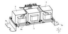
- FIG. 6 is a perspective view illustrating the arrangement of the plurality of transformers 3 according to the first embodiment.
- a plurality of transformers 3 can be provided in the transformer box 4 .
- three transformers 3 are arranged horizontally on the bottom panel 4d of the transformer box 4.
- the bottom panel 4d of the transformer box 4 is supported from below by two legs 4e.
- Wiring connected to the transformer 3 is housed in a transformer box 4 together with the transformer 3.
- the transformer box 4 is provided on the pedestal 11. Further, the pedestal 11 is supported by a water pump box 6 and support legs 7. Therefore, even if the length of a plurality of transformers 3 when placed horizontally exceeds the length of the water pump box 6 in the left and right direction of the heat pump heat source device 100, the water pump box 6 and the support legs 7 can support the mount 11. can be supported. Therefore, the number of transformers 3 housed in the transformer box 4 is not limited by the length of the water pump box 6 in the left-right direction. The number of transformers 3 is not limited to three, and may be two or less or four or more.
- the plurality of transformers 3 When storing a plurality of transformers 3 in the transformer box 4, as shown in FIG. 6, by arranging the plurality of transformers 3 horizontally on the bottom panel 4d, the plurality of transformers 3 can be arranged vertically.
- the height of the transformer boxes 4 is not increased compared to when they are arranged side by side. Therefore, there is no need to increase the height of the casing 101 in order to store the transformer box 4 inside the casing 101.
- the center of gravity of the housing 101 is lowered. That is, by arranging a plurality of transformers 3 horizontally and storing them in the transformer box 4, the height of the casing 101 does not become too high, and the center of gravity of the casing 101 can be lowered. Therefore, the housing 101 is stabilized.
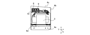
- FIG. 7 is a perspective view showing the internal configuration of the transformer box 4 according to the embodiment.
- the transformer box 4 is shown with the front panel 4a and top panel 4c of the transformer box 4 removed.
- FIG. 8 is a plan view of the transformer box 4 in the state shown in FIG.
- FIG. 9 is a front view of the transformer box 4 in the state shown in FIG.
- FIG. 10 is a side perspective view of the transformer box 4 in the state shown in FIG.
- the transformer box 4 houses a fuse 8, a fuse box 9, and a fuse stand 10.
- the fuse stand 10 is provided on the bottom panel 4d of the transformer box 4 so as to cover the left and right side surfaces and the top surface of one transformer 3.
- the fuse box 9 is provided on the upper surface of the fuse stand 10.
- a fuse 8 is housed inside the fuse box 9.
- a plurality of fuses 8 may be housed in the fuse box 9.
- the fuse 8 and each transformer 3 are connected by wiring. As shown in FIGS. 7 to 10, the wiring can be branched using terminals inside the fuse box 9. Therefore, the number of terminal blocks can be reduced.
- the fuse stand 10 can be used as a fixing device for fixing a wiring connector.
- a connection connector is provided on the rear side of the fuse stand 10.
- the fuse box 9 is provided on the front side of the fuse stand 10. That is, the fuse box 9 is located at the upper front side of the transformer 3. Wiring from each transformer 3 and fuse 8 is connected to a connector on the rear side of the fuse stand 10.
- the space between the bottom panel 4d of the transformer box 4 and the pedestal 11 described above can be used as a space for storing the wires connected to each transformer 3 and the fuse 8, as shown in FIG. Note that the fuse box 9 does not need to be located at the forefront of the fuse stand 10, and the connection connector does not need to be located at the rear side of the fuse stand 10.
- a connection connector may be provided on the front side of the fuse box 9.
- the fuse box 9 is located on the front side within the transformer box 4. Therefore, the front panel 4a of the transformer box 4 can be removed to easily replace the fuse 8 housed in the fuse box 9. Further, since the fuse 8 is provided inside the transformer box 4, work such as inspection, maintenance, or repair of each transformer 3 can be performed inside the transformer box 4.
- the front panel 4a and top panel 4c of the transformer box 4 are each removable. Furthermore, the transformer box 4 is removable from the pedestal 11 with the transformer 3 housed therein. Therefore, even if components such as the panel 12, power supply wiring, and piping are arranged in front of the front panel 4a of the transformer box 4, the transformer box 4 can be fixed to the pedestal 11 as necessary. By removing the front panel 4a or top panel 4c or removing the transformer box 4 from the pedestal 11, inspection, maintenance, or repair work can be performed on each transformer 3 and fuse 8. .
- the fuse 8 is housed in the transformer box 4, and the control device 1 is housed in the control device box 2. Therefore, the fuse 8 is less affected by the heat of the control device 1, and the temperature of the fuse 8 is prevented from increasing. Therefore, in the heat pump heat source device 100, problems caused by a rise in temperature of the fuse 8 can be suppressed.
- the shapes of the wiring connectors of each transformer 3 may all be different shapes. By making the shapes of the wiring connectors different, it is possible to suppress incorrect connection of the wiring inside the transformer box 4.
- FIG. 11 is a plan view showing the bundling of wiring within the transformer box 4 according to the embodiment.
- FIG. 12 is a front view showing the bundling of wiring within the transformer box 4 according to the embodiment.
- the transformer box 4 is provided with a cable strap 4f, a wire saddle 4g, and an edge saddle 4h for bundling the wires.
- a plurality of cable straps 4f, wire saddles 4g, and edge saddles 4h are each provided. It is not necessary to use all the cable straps 4f, wire saddles 4g, and edge saddles 4h provided in the transformer box 4 for bundling the wiring. If necessary, the wiring may be bundled using the cable strap 4f, wire saddle 4g, and edge saddle 4h.
- the cable strap 4f is annular and ties together a plurality of wires.
- the cable strap 4f is also provided on the outside of the transformer box 4, and bundles the wiring extending from the inside of the transformer box 4 to the outside of the transformer box 4.
- the wire saddle 4g bundles multiple wires together.
- the shape of the wire saddle 4g is not limited.
- the wire saddle 4g has a rectangular or circular shape with a removable notch into which a wire can be inserted.
- the edge saddle 4h bundles multiple wires together.
- the edge saddle 4h prevents the wiring passing through the front panel 4a, bottom panel 4d, etc. of the transformer box 4 from being damaged at corners, ends, etc.
- an edge saddle 4h is provided in the notch.
- the heat pump heat source device 100 includes a casing 101 having a bottom plate 102, a water pump box 6 that houses the water pump 5, and a water pump box 6 provided on the front side of the bottom plate 102.
- the transformer box 4 includes a transformer box 4 provided above the box 6 to accommodate the transformer 3, and a control device box 2 provided above the transformer box 4 to accommodate the control device 1.
- control device 1 and the transformer 3 are provided above the water pump box 6. Therefore, when water leaks inside the casing 101 of the heat pump heat source device 100, the control device 1 and the transformer 3 are prevented from being submerged or submerged in water.
- the water pump box 6, transformer box 4, and control device box 2 are arranged in the vertical direction of the heat pump heat source device 100 inside the housing 101. Therefore, in the front-rear direction of the heat pump heat source device 100, the water pump box 6, transformer box 4, and control device box 2 do not overlap. Therefore, the water pump 5, transformer 3, and control device 1 can be inspected, maintained, or repaired individually. Further, when inspecting, maintaining, or repairing each of the water pump 5, transformer 3, and control device 1, each of them does not become a factor that impedes the work. That is, the water pump 5, transformer 3, and control device 1 do not affect each other's serviceability.
- the transformer 3 is provided between the water pump box 6 and the control device box 2. That is, inside the housing 101, the water pump 5 and the transformer 3 are provided below the control device box 2, so that the center of gravity of the housing 101 can be lowered.
- the transformer box 4 is provided on the ceiling of the water pump box 6.
- the ceiling of the water pump box 6 is a pedestal 11 provided between the water pump box 6 and the transformer box 4.
- the pedestal 11 which is the ceiling of the water pump box 6 is provided between the water pump box 6 and the transformer box 4
- the transformer box 4 is provided on the pedestal 11 and the bottom surface of the transformer box 4.
- Panel 4d is fixed to pedestal 11 via screws.
- the transformer box 4 that houses the transformer 3 is provided on a pedestal 11 that is the ceiling of the water pump box 6. Normally, when the transformer is provided on the rear side inside the casing, the workability of inspecting, maintaining, or repairing the transformer deteriorates.
- the transformer box 4 provided on the ceiling of the water pump box 6 is also located on the front side of the housing 101. Therefore, the workability of inspecting, maintaining, or repairing the transformer 3 housed in the transformer box 4 does not deteriorate. Furthermore, since the transformer box 4 is fixed to the mount 11 that is the ceiling of the water pump box 6, the number of parts inside the housing 102 can be reduced, and the space inside the housing 102 can be used efficiently. .
- the heat pump heat source device 100 has support legs 7 that are provided on the bottom plate 102 in line with the water pump box 6 and support the transformer box 4 from below. Therefore, even if the length of the transformer box 4 is longer than the length of the water pump box 6 in the left-right direction of the heat pump heat source device 100, the transformer box 4 can be provided on the water pump box 6.
- a space is provided between the support leg 7 and the water pump box 6. Therefore, the space between the support leg 7 and the water pump box 6 can be used for inspection, maintenance, or repair of the water pump 5.
- the water pump box 6 of the heat pump heat source device 100 has a removable front panel 6a that covers the front surface of the water pump box 6.
- the front panel 6a of the water pump box 6 includes a first front panel 6a-1 and a second front panel 6a-2 provided below the first front panel 6a-1. Therefore, even if another component such as piping is provided on the front of the water pump box 6, each or both of the first front panel 6a-1 and the second front panel 6a-2 can be removed.
- the water pump 5 housed in the water pump box 6 can be inspected, maintained, or repaired.
- the transformer box 4 of the heat pump heat source device 100 houses a plurality of transformers 3, and the plurality of transformers 3 are housed in the transformer box 4 side by side in the horizontal direction. Therefore, there is no need to increase the height of the transformer box 4. Therefore, the height of the housing 101 can be suppressed, and the center of gravity of the housing 101 can be lowered.
- the transformer box 4 of the heat pump heat source device 100 includes a fuse box 9 and a fuse 8 housed in the fuse box 9. 8 is connected. Therefore, work such as inspection, maintenance, or repair of the transformer 3 can be performed inside the transformer box 4. Further, since the fuse 8 and the control device 1 are separated by the transformer box 4 and the control device box 2, the fuse 8 is not easily affected by the heat of the control device 1. Therefore, the temperature rise of the fuse 8 is suppressed, and malfunctions of the fuse 8 are suppressed. Therefore, malfunctions of the heat pump heat source device 100 can be suppressed.
- a fuse stand 10 is provided above the transformer 3, and a fuse box 9 is provided above the fuse stand 10. .
- the fuse stand 10 can also be used as a fixture for fixing the connectors of the transformer 3 and the fuse 8 wires housed in the transformer box 4. Therefore, it is possible to suppress the wiring from becoming complicated inside the transformer box 4.
- the fuse box 9 is located on the front side of the transformer box 4 above the fuse stand 10. Therefore, the front panel 4a of the transformer box 4 can be removed to easily replace the fuse 8 housed in the fuse box 9.
- the transformer box 4 of the heat pump heat source device 100 includes a removable top panel 4c and a removable front panel 4a. Therefore, by removing either or both of the top panel 4c and the front panel 4a, the transformer 3 housed in the transformer box 4 can be inspected, maintained, or repaired.
Landscapes
- Engineering & Computer Science (AREA)
- Mechanical Engineering (AREA)
- General Engineering & Computer Science (AREA)
- Chemical & Material Sciences (AREA)
- Combustion & Propulsion (AREA)
- Microelectronics & Electronic Packaging (AREA)
- Physics & Mathematics (AREA)
- Thermal Sciences (AREA)
- Heat-Pump Type And Storage Water Heaters (AREA)
Priority Applications (3)
| Application Number | Priority Date | Filing Date | Title |
|---|---|---|---|
| JP2024507403A JPWO2023175900A1 (https=) | 2022-03-18 | 2022-03-18 | |
| PCT/JP2022/012622 WO2023175900A1 (ja) | 2022-03-18 | 2022-03-18 | ヒートポンプ熱源機 |
| US18/724,920 US20250063690A1 (en) | 2022-03-18 | 2022-03-18 | Heat-pump heat source apparatus |
Applications Claiming Priority (1)
| Application Number | Priority Date | Filing Date | Title |
|---|---|---|---|
| PCT/JP2022/012622 WO2023175900A1 (ja) | 2022-03-18 | 2022-03-18 | ヒートポンプ熱源機 |
Publications (1)
| Publication Number | Publication Date |
|---|---|
| WO2023175900A1 true WO2023175900A1 (ja) | 2023-09-21 |
Family
ID=88022636
Family Applications (1)
| Application Number | Title | Priority Date | Filing Date |
|---|---|---|---|
| PCT/JP2022/012622 Ceased WO2023175900A1 (ja) | 2022-03-18 | 2022-03-18 | ヒートポンプ熱源機 |
Country Status (3)
| Country | Link |
|---|---|
| US (1) | US20250063690A1 (https=) |
| JP (1) | JPWO2023175900A1 (https=) |
| WO (1) | WO2023175900A1 (https=) |
Citations (8)
| Publication number | Priority date | Publication date | Assignee | Title |
|---|---|---|---|---|
| JPS50134882A (https=) * | 1974-04-16 | 1975-10-25 | ||
| JPS5673110U (https=) * | 1979-11-08 | 1981-06-16 | ||
| JPS5780231A (en) * | 1980-11-05 | 1982-05-19 | Hitachi Ltd | Transformer protecting relay |
| JP3095130U (ja) * | 2003-01-08 | 2003-07-25 | 金邦電気株式会社 | 低圧分岐端子箱 |
| JP2015137615A (ja) * | 2014-01-23 | 2015-07-30 | コベルコ建機株式会社 | 建設機械 |
| JP2017127096A (ja) * | 2016-01-13 | 2017-07-20 | 株式会社Lixil | 外構用電源装置 |
| JP2017166756A (ja) * | 2016-03-16 | 2017-09-21 | 東芝キヤリア株式会社 | 冷凍サイクル装置の室外機 |
| JP3224926U (ja) * | 2019-11-19 | 2020-01-30 | 株式会社電業社 | ドレン排水試験装置 |
Family Cites Families (7)
| Publication number | Priority date | Publication date | Assignee | Title |
|---|---|---|---|---|
| JP4314934B2 (ja) * | 2003-08-29 | 2009-08-19 | ダイキン工業株式会社 | 室外ユニットの電装品ユニット及びそれを備えた空気調和装置の室外ユニット |
| JP5423322B2 (ja) * | 2009-11-04 | 2014-02-19 | ダイキン工業株式会社 | 空気調和機の室外機 |
| US8634182B2 (en) * | 2010-01-18 | 2014-01-21 | Lennox Industries, Inc. | Premises power source accessory panel for an outdoor unit and method of adapting an outdoor unit with the same |
| US20130255932A1 (en) * | 2012-03-30 | 2013-10-03 | Emerson Climate Technologies, Inc. | Heat sink for a condensing unit and method of using same |
| KR102409975B1 (ko) * | 2020-09-07 | 2022-06-15 | 엘지전자 주식회사 | 공기조화기 |
| WO2023243023A1 (ja) * | 2022-06-16 | 2023-12-21 | 三菱電機株式会社 | 室外機の制御箱 |
| JP2024005994A (ja) * | 2022-06-30 | 2024-01-17 | 株式会社富士通ゼネラル | 室外機及びこれを備えた空気調和機 |
-
2022
- 2022-03-18 WO PCT/JP2022/012622 patent/WO2023175900A1/ja not_active Ceased
- 2022-03-18 US US18/724,920 patent/US20250063690A1/en active Pending
- 2022-03-18 JP JP2024507403A patent/JPWO2023175900A1/ja active Pending
Patent Citations (8)
| Publication number | Priority date | Publication date | Assignee | Title |
|---|---|---|---|---|
| JPS50134882A (https=) * | 1974-04-16 | 1975-10-25 | ||
| JPS5673110U (https=) * | 1979-11-08 | 1981-06-16 | ||
| JPS5780231A (en) * | 1980-11-05 | 1982-05-19 | Hitachi Ltd | Transformer protecting relay |
| JP3095130U (ja) * | 2003-01-08 | 2003-07-25 | 金邦電気株式会社 | 低圧分岐端子箱 |
| JP2015137615A (ja) * | 2014-01-23 | 2015-07-30 | コベルコ建機株式会社 | 建設機械 |
| JP2017127096A (ja) * | 2016-01-13 | 2017-07-20 | 株式会社Lixil | 外構用電源装置 |
| JP2017166756A (ja) * | 2016-03-16 | 2017-09-21 | 東芝キヤリア株式会社 | 冷凍サイクル装置の室外機 |
| JP3224926U (ja) * | 2019-11-19 | 2020-01-30 | 株式会社電業社 | ドレン排水試験装置 |
Also Published As
| Publication number | Publication date |
|---|---|
| JPWO2023175900A1 (https=) | 2023-09-21 |
| US20250063690A1 (en) | 2025-02-20 |
Similar Documents
| Publication | Publication Date | Title |
|---|---|---|
| JP2010038514A (ja) | ヒートポンプ装置 | |
| CN203823951U (zh) | 空调装置的室外机 | |
| KR101320001B1 (ko) | 냉각 시스템 및 방법 | |
| CN115149149A (zh) | 一种储能电池柜 | |
| JP3223099B2 (ja) | 冷凍装置 | |
| KR102168620B1 (ko) | 공기조화기의 실외기 | |
| JP4721943B2 (ja) | 空気調和装置の室外機 | |
| EP1959204A1 (en) | Air/water heat exchange apparatus | |
| WO2023175900A1 (ja) | ヒートポンプ熱源機 | |
| JP4373755B2 (ja) | 空気調和機の室外機 | |
| CN221574037U (zh) | 一种管式直接换热的储能电池pack | |
| JP5155057B2 (ja) | ヒートポンプ装置 | |
| JP7582363B2 (ja) | 空気調和機の室外機 | |
| CN108878710B (zh) | 高效温控动力电池箱 | |
| JP7653760B2 (ja) | 空気調和機の室外機 | |
| JP2026069273A (ja) | 取付器具、および、アクティブフィルタ装置の取り付け方法 | |
| JP2024005994A (ja) | 室外機及びこれを備えた空気調和機 | |
| CN219037103U (zh) | 热水发生器安装结构、热水发生器及空调器 | |
| CN223884549U (zh) | 壁挂安装架及壁挂供电装置 | |
| JP7534713B2 (ja) | 空気調和機の室外機 | |
| CN104279750B (zh) | 热水贮存单元及热水供给装置 | |
| EP4279826A1 (en) | Heat pump cycle device | |
| CN220852513U (zh) | 双风道固定装置和空调 | |
| CN223283294U (zh) | 空调器 | |
| CN218379666U (zh) | 电控盒及空调装置 |
Legal Events
| Date | Code | Title | Description |
|---|---|---|---|
| 121 | Ep: the epo has been informed by wipo that ep was designated in this application |
Ref document number: 22932173 Country of ref document: EP Kind code of ref document: A1 |
|
| ENP | Entry into the national phase |
Ref document number: 2024507403 Country of ref document: JP Kind code of ref document: A |
|
| WWE | Wipo information: entry into national phase |
Ref document number: 18724920 Country of ref document: US |
|
| NENP | Non-entry into the national phase |
Ref country code: DE |
|
| 122 | Ep: pct application non-entry in european phase |
Ref document number: 22932173 Country of ref document: EP Kind code of ref document: A1 |