WO2023166638A1 - Céramique composite, élément luminophore, dispositif d'éclairage laser et procédé de fabrication d'élément composite - Google Patents
Céramique composite, élément luminophore, dispositif d'éclairage laser et procédé de fabrication d'élément composite Download PDFInfo
- Publication number
- WO2023166638A1 WO2023166638A1 PCT/JP2022/009002 JP2022009002W WO2023166638A1 WO 2023166638 A1 WO2023166638 A1 WO 2023166638A1 JP 2022009002 W JP2022009002 W JP 2022009002W WO 2023166638 A1 WO2023166638 A1 WO 2023166638A1
- Authority
- WO
- WIPO (PCT)
- Prior art keywords
- component
- composite ceramics
- phosphor
- nitride
- composite
- Prior art date
Links
Images


Classifications
-
- C—CHEMISTRY; METALLURGY
- C09—DYES; PAINTS; POLISHES; NATURAL RESINS; ADHESIVES; COMPOSITIONS NOT OTHERWISE PROVIDED FOR; APPLICATIONS OF MATERIALS NOT OTHERWISE PROVIDED FOR
- C09K—MATERIALS FOR MISCELLANEOUS APPLICATIONS, NOT PROVIDED FOR ELSEWHERE
- C09K11/00—Luminescent, e.g. electroluminescent, chemiluminescent materials
- C09K11/08—Luminescent, e.g. electroluminescent, chemiluminescent materials containing inorganic luminescent materials
- C09K11/55—Luminescent, e.g. electroluminescent, chemiluminescent materials containing inorganic luminescent materials containing beryllium, magnesium, alkali metals or alkaline earth metals
-
- C—CHEMISTRY; METALLURGY
- C09—DYES; PAINTS; POLISHES; NATURAL RESINS; ADHESIVES; COMPOSITIONS NOT OTHERWISE PROVIDED FOR; APPLICATIONS OF MATERIALS NOT OTHERWISE PROVIDED FOR
- C09K—MATERIALS FOR MISCELLANEOUS APPLICATIONS, NOT PROVIDED FOR ELSEWHERE
- C09K11/00—Luminescent, e.g. electroluminescent, chemiluminescent materials
- C09K11/08—Luminescent, e.g. electroluminescent, chemiluminescent materials containing inorganic luminescent materials
- C09K11/59—Luminescent, e.g. electroluminescent, chemiluminescent materials containing inorganic luminescent materials containing silicon
-
- C—CHEMISTRY; METALLURGY
- C09—DYES; PAINTS; POLISHES; NATURAL RESINS; ADHESIVES; COMPOSITIONS NOT OTHERWISE PROVIDED FOR; APPLICATIONS OF MATERIALS NOT OTHERWISE PROVIDED FOR
- C09K—MATERIALS FOR MISCELLANEOUS APPLICATIONS, NOT PROVIDED FOR ELSEWHERE
- C09K11/00—Luminescent, e.g. electroluminescent, chemiluminescent materials
- C09K11/08—Luminescent, e.g. electroluminescent, chemiluminescent materials containing inorganic luminescent materials
- C09K11/64—Luminescent, e.g. electroluminescent, chemiluminescent materials containing inorganic luminescent materials containing aluminium
Definitions
- the present disclosure relates to composite ceramics containing a garnet-based phosphor component, a nitride-based phosphor component, and a matrix component, a phosphor element and a laser illumination device having the same, and a method for manufacturing the composite ceramics.
- Laser lighting devices are more energy efficient, compact, and brighter than other lighting devices, and have already begun to be put into practical use as lighting devices for projectors and automobile headlights. Also, in the home lighting market, replacement of existing LED (light emitting diode) lighting devices and fluorescent lamps with laser lighting devices is expected, and the laser lighting market is expected to expand rapidly in the future.
- LED light emitting diode
- Patent Document 1 discloses, as composite ceramics, ceramics containing a phosphor phase made of YAG containing Ce, a matrix phase made of at least one of Al 2 O 3 and AlN, and impurities within a predetermined range. A composite is disclosed.
- Patent Document 2 As a composite ceramic, a fluorescent substance molded body is produced by sintering a mixture of AlN powder and phosphor powder by a discharge plasma sintering method, melting the AlN powder, and then cooling it. is disclosed.
- the red phosphor means a phosphor that emits red to orange light.
- Patent Document 2 discloses that a nitride-based phosphor may be used as the phosphor powder.
- a composite ceramic according to one aspect of the present disclosure is a composite ceramic made of a sintered body containing a garnet phosphor component, a nitride phosphor component, and a matrix component, , the matrix component is at least one selected from the group consisting of MgO and Al 2 O 3 , the content of the matrix component is in the range of 31 wt% or more and 95 wt% or less of the total components, and the matrix component surrounds the garnet-based phosphor component and the nitride-based phosphor component and is sintered.
- a phosphor element according to one aspect of the present disclosure includes composite ceramics according to one aspect of the present disclosure, and a base material for fixing the composite ceramics.
- a laser illumination device includes a phosphor element according to one aspect of the present disclosure, and a laser light source that irradiates the composite ceramics in the phosphor element with excitation light. and a condensing member condensing light output from the composite ceramics in the phosphor element.
- a method for manufacturing a composite ceramic mixes a first raw material powder containing a garnet-based phosphor component, a nitride-based phosphor component, and a matrix component.
- a composite ceramic containing a red phosphor for laser illumination which can be produced relatively easily, a phosphor element and a laser illumination device including the same, and the It is possible to provide a method for producing such composite ceramics.
- FIG. 1 is a cross-sectional view showing an example of the structure of composite ceramics according to Embodiment 1.
- FIG. 3 is a flow chart showing an example of a method for manufacturing composite ceramics according to Embodiment 1.
- FIG. FIG. 5 is a cross-sectional view showing an example of the structure of composite ceramics according to Embodiment 2;
- FIG. 10 is a cross-sectional view showing an example of the structure of composite ceramics according to Embodiment 3;
- FIG. 10 is a cross-sectional view showing an example of the structure of composite ceramics according to Embodiment 4;
- FIG. 10 is a diagram showing a composite ceramic having one main surface provided with an antireflection coating film according to Embodiment 5;
- FIG. 11 is a cross-sectional view showing an example of a phosphor element according to Embodiment 5; 8 is a flow chart showing an example of a method for manufacturing the phosphor element shown in FIG. 7.
- FIG. FIG. 12 is a cross-sectional view showing an example of a laser illumination device according to Embodiment 6; 3 is a ternary diagram showing the contents of nitride-based phosphor components, matrix components, and garnet-based phosphor components in Examples 1 to 3 and Comparative Example 1.
- FIG. 1 is a diagram showing an XRD pattern of composite ceramics obtained in Example 1.
- FIG. 1 is a graph showing laser power dependence of fluorescence power of composite ceramics obtained in Example 1.
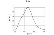
- FIG. 1 is a diagram showing fluorescence spectra of composite ceramics obtained in Example 1.
- FIG. FIG. 10 is a diagram showing an example of a SEM image of composite ceramics obtained in Example 2; 3 is a diagram showing an XRD pattern of composite ceramics obtained in Example 2.
- FIG. FIG. 4 is a graph showing laser power dependence of the fluorescence power of composite ceramics obtained in Example 2.
- FIG. 4 is a diagram showing fluorescence spectra of composite ceramics obtained in Example 2.
- FIG. 10 is a graph showing laser power dependence of the fluorescence power of composite ceramics obtained in Example 3.
- FIG. 10 is a diagram showing fluorescence spectra of composite ceramics obtained in Example 3; 4 is a graph showing laser power dependence of fluorescence power of composite ceramics obtained in Comparative Example 1.
- FIG. 2 is a diagram showing fluorescence spectra of composite ceramics obtained in Comparative Example 1.
- FIG. FIG. 10 is a ternary diagram showing the contents of nitride-based phosphor components, matrix components, and garnet-based phosphor components in Examples 4 and 5;
- FIG. 10 is a graph showing laser power dependence of the fluorescence power of composite ceramics obtained in Example 4.
- FIG. FIG. 10 is a diagram showing fluorescence spectra of composite ceramics obtained in Example 4;
- FIG. 10 is a graph showing laser power dependence of fluorescence power of composite ceramics obtained in Examples 4 and 5;
- FIG. 1 is a cross-sectional view showing an example of the structure of a composite ceramic 1 according to this embodiment.
- the composite ceramic 1 according to this embodiment is a multi-wavelength luminescent ceramic composite made of a sintered body containing phosphor components having two or more emission wavelengths and a matrix component.
- the composite ceramic 1 shown in FIG. 1 includes a garnet-based phosphor component 2, a nitride-based phosphor component 3, and a matrix component 4, and the matrix component 4 includes the garnet-based phosphor component 2 and the nitride-based phosphor. It has a sintered structure surrounding component 3.
- the composite ceramic 1 has a sea-island structure in which the garnet-based phosphor component 2 and the nitride-based phosphor component 3 are mixed in islands in the matrix component 4 . That is, the composite ceramic 1 has a structure in which the garnet-based phosphor component 2 and the nitride-based phosphor component 3 are dispersed like islands in a relatively continuous sea-like matrix component 4 . A matrix component 4 is filled between the garnet phosphor component 2 and the nitride phosphor component 3 .
- the garnet-based phosphor component 2, the nitride-based phosphor component 3, and the matrix component 4 are adhered to each other.
- the composite ceramic 1 comprises at least three phases of a first phosphor phase comprising a garnet phosphor component 2, a second phosphor phase comprising a nitride phosphor component 3, and a matrix phase comprising a matrix component 4. have phases.
- the composite ceramic 1 has a structure in which at least the above three phases are mixed and phases adjacent to each other are fixed.
- the structure in which at least the above three phases are mixed and the phases adjacent to each other are fixed means that the above three phases are not solid-dissolved, but are separated into regions of each phase in the solid, and the phases adjacent to each other are separated. A sticking structure is shown. It also includes the case where sintering aids and impurities are present at grain boundaries. Alternatively, even if there are slight alteration phases or melting phases between particles, if they basically have a solid three-phase structure, they are considered composite ceramics.
- Composite ceramics 1 excludes joints in which three or more phases are simply directly joined, and compositions in which at least the three phases are solidified by at least one of inorganic glass and organic binder.
- the garnet-based phosphor component 2 indicates a phosphor having a garnet crystal structure.
- the garnet-based phosphor component 2 is a phosphor having a large refractive index and excellent fluorescence characteristics, and emits yellowish to greenish yellowish fluorescence, for example, by blue excitation light.
- the light that does not contribute to the excitation among the excitation light is scattered and transmitted. Therefore, the garnet-based phosphor component 2 outputs blue scattered light and yellowish fluorescence.
- the garnet-based phosphor component 2 has excellent heat resistance, and can suppress deterioration even when irradiated with, for example, a high-power excitation light LD (laser diode).
- a high-power excitation light LD laser diode
- a YAG (yttrium-aluminum-garnet)-based phosphor can be used as the garnet-based phosphor component 2.
- the YAG-based phosphor indicates a phosphor that can be attributed to the crystal structure of the YAG phosphor.
- YAG phosphors examples include (Ce, Y) 3 Al 5 O 12 , (Ce, Lu) 3 Al 5 O 12 , (Ce, Lu, Y) 3 Al 5 O 12 , (Ce, Lu, Y ) 3 (Al, Ga) 5 O 12 .
- the YAG phosphor as the garnet phosphor component 2 in the composite ceramic 1, it is possible to easily realize the composite ceramic 1 that outputs yellowish to greenish yellow fluorescence.
- the composite ceramics 1 contains the YAG-based phosphor as the garnet-based phosphor component 2, the composite ceramics 1 having more excellent fluorescence characteristics can be obtained.
- the nitride-based phosphor component 3 indicates a phosphor containing nitrogen.
- Specific examples of the nitride phosphor component 3 include at least one phosphor selected from the group consisting of nitride phosphors and oxynitride phosphors.
- the nitride-based phosphor component 3 is a red-based phosphor that emits red-to-orange red-based fluorescence with excellent fluorescence properties. For example, it emits red-based fluorescence with blue excitation light. In addition, the light that does not contribute to the excitation among the excitation light is scattered and transmitted. Therefore, the nitride phosphor component 3 outputs blue scattered light and red fluorescence.
- the composite ceramic 1 contains the nitride-based phosphor component 3, the composite ceramic 1 having more excellent fluorescence characteristics can be obtained.
- nitride-based phosphor component 3 examples include Sr 2 Si 5 N 8 , (Sr, Ba) 2 Si 5 N 8 , (Ca, Sr, Ba) at least one nitride phosphor selected from the group consisting of 2Si5N8 .
- these nitride phosphors may be referred to as nitride phosphor (A).
- Eu and Ce are activators and are doped in the crystal.
- nitride- based phosphor component 3 for example, Eu:Sr2Si5N8, Eu:(Sr,Ba)2Si5N8 , Eu : ( Ca , Sr , Ba) 2Si5 N 8 , Ce: Sr 2 Si 5 N 8 , Ce: (Sr, Ba) 2 Si 5 N 8 , Ce: (Ca, Sr, Ba) Si 5 N 8 , (Eu, Ce): Sr 2 Si 5 N 8 , (Eu, Ce): (Sr, Ba) 2 Si 5 N 8 , (Eu, Ce): (Ca, Sr, Ba) 2 Si 5 N 8 and other nitride phosphors (A).
- the composite ceramic 1 that emits stable reddish fluorescence can be produced.
- nitride phosphors At least one of part of Si and part of N in the above composition formula may be substituted.
- Si When part of Si is substituted, Si is substituted with Al.
- N is replaced with O when part of N is replaced.
- the nitride-based phosphor component 3 is Sr 2 Si 5 N 8 , (Sr, Ba) 2 Si 5 N 8 , or (Ca, Sr, Ba) 2 Si 5 N 8 , in which part of Si is Al It may be a nitride phosphor in which N is substituted with or an oxynitride phosphor in which a part of N is replaced with O. Further, an oxynitride phosphor in which part of Si is replaced with Al and part of N is replaced with O may be used. As an example, for example, for example, (Sr, Ba) 2 (Si, Al) 5 N 8 , (Sr, Ba) 2 (Si, Al) 5 (N, O ) 8 and the like.
- nitride-based phosphor component 3 By including at least one of such a nitride phosphor and an oxynitride phosphor as the nitride-based phosphor component 3 in the composite ceramic 1, a more reliable composite ceramic 1 can be realized.
- the nitride-based phosphor component 3 is, for example, at least one nitride phosphor selected from the group consisting of CaAlSiN 3 and (Ca, Sr)AlSiN 3 activated with at least one element of Eu and Ce, respectively. It can be a body.
- these nitride phosphors may be referred to as nitride phosphor (B).
- Eu and Ce are activators and are doped in the crystal.
- the nitride-based phosphor component 3 includes, for example, Eu:CaAlSiN 3 , Eu:(Ca,Sr)AlSiN 3 , Ce:CaAlSiN 3 , Ce:(Ca,Sr)AlSiN 3 , (Eu, Ce ): CaAlSiN 3 , (Eu, Ce): (Ca, Sr) AlSiN 3 and other nitride phosphors (B).
- nitride-based phosphor component 3 in addition to the nitride phosphor (A) and the nitride phosphor (B), for example, Ce-activated (La, Y) 3 Si 6 N 11 , etc. There may be.
- nitride phosphors (A) and nitride phosphors (B), and nitride phosphors other than these nitride phosphors (A) and nitride phosphors (B) may be used separately. They may be used together as long as they do not dissolve or react with each other.
- Matrix component 4 is at least one selected from the group consisting of MgO (magnesium oxide) and Al 2 O 3 (aluminum oxide).
- the matrix component 4 may be MgO, Al 2 O 3 , or a mixture of MgO and Al 2 O 3 .
- the composite ceramic 1 according to this embodiment has an excitation light power resistance of 0.5 kW/cm 2 or more.
- the composite ceramic 1 according to the present embodiment is a composite ceramic for low color temperature, which has a high fluorescence power with respect to the excitation light power, can withstand laser excitation, and has a high excitation light power resistance. Therefore, according to this embodiment, it is possible to realize a phosphor element for a laser that is practical and does not saturate fluorescence even at relatively high power.
- the upper limit is not particularly limited.
- the upper limit of the pumping light power resistance is 100 kW/cm 2 from the pumping light power resistance (laser power resistance) of practically available laser light sources and various optical components. Therefore, it is desirable that the excitation light power resistance of the composite ceramics 1 according to this embodiment is in the range of 0.5 kW/cm 2 or more and 100 kW/cm 2 or less.
- the excitation light power tolerance indicates a value at which fluorescence power is saturated with respect to excitation light power (specifically, laser excitation light power) per 1 cm 2 .
- the excitation light power resistance can be measured by a phosphor evaluation device equipped with a laser light source, an integrating sphere, and a spectroscope.
- the content of the matrix component 4 in the composite ceramics 1 is within the range of 31 wt % or more and 95 wt % or less of the total components in the composite ceramics 1 .
- the composite ceramic 1 is a composite ceramic made of a sintered body containing the garnet phosphor component 2, the nitride phosphor component 3, and the matrix component 4, and the matrix component 4 is at least one selected from the group consisting of MgO and Al 2 O 3 , the content of matrix component 4 is in the range of 31 wt % or more and 95 wt % or less of all components, and matrix component 4 is garnet The phosphor component 2 and the nitride phosphor component 3 are surrounded and sintered.
- the content of the matrix component 4 in the composite ceramics 1 is set closer to the upper limit within the above range. Therefore, the content of the matrix component 4 in the composite ceramics 1 is more preferably 45 wt % or more, more preferably 60 wt % or more.
- the content of the matrix component 4 in the composite ceramic 1 is in the range of 31 wt% or more and 95 wt% or less of the total components, and is in the range of 31 wt% or more and 90 wt% or less of the total components. more preferred.
- the total content of the garnet-based phosphor component 2 and the nitride-based phosphor component 3 in the composite ceramics 1 is preferably in the range of 5 wt % or more and 69 wt % or less of all components in the composite ceramics 1 .
- the matrix component 4 surrounds the garnet-based phosphor component 2 and the nitride-based phosphor component 3 and is sintered to form the composite ceramic 1 having a structure in which adjacent phases adhere to each other. Obtainable.
- the respective contents of the garnet-based phosphor component 2 and the nitride-based phosphor component 3 in the composite ceramic 1 may be appropriately set so that the total content of these components falls within the above range, and is particularly limited. isn't it.
- the garnet-based phosphor component 2 emits yellow fluorescence or green fluorescence with blue excitation light, as described above.
- the nitride phosphor component 3 emits red fluorescence when exposed to blue excitation light.
- these phosphors scatter and transmit the light that did not contribute to the excitation among the excitation light. Therefore, when the composite ceramics 1 is irradiated with blue excitation light, the composite ceramics 1 outputs reddish bulb-colored light in which blue scattered light, yellowish fluorescence, and reddish fluorescence are mixed. be.
- the content of the garnet-based phosphor component 2 in the composite ceramics 1 is preferably in the range of 2 wt% or more and 65 wt% or less of the total components in the composite ceramics 1, and is in the range of 2 wt% or more and 59 wt% or less. It is more preferable to be in the range of 4 wt % or more and 59 wt % or less.
- the content of the nitride-based phosphor component 3 in the composite ceramic 1 is preferably in the range of 2 wt% or more and 65 wt% or less of all the components in the composite ceramic 1, and is in the range of 2 wt% or more and 59 wt% or less. more preferably within the range of 4 wt % or more and 59 wt % or less.
- the light bulb also contains red to orange red fluorescence, which is particularly suitable for home lighting devices, projector lighting devices, automobile headlights, outdoor lighting, and particularly remote lighting devices. Color emission spectra can be obtained.
- the content of the nitride-based phosphor component 3 in the composite ceramic 1 increases, the fluorescence power tends to saturate with respect to the excitation light power. Therefore, by reducing the content of the nitride-based phosphor component 3 in the composite ceramic 1, it is possible to further improve the excitation light power resistance. Therefore, the content of the nitride-based phosphor component 3 in the composite ceramic 1 is preferably set at the lower limit within the above range. Therefore, the content of the nitride-based phosphor component 3 in the composite ceramic 1 is more preferably 60 wt % or less, more preferably 40 wt % or less.
- the composite ceramic 1 is shown in FIGS.
- the contents of the nitride-based phosphor component 3, the matrix component 4, and the garnet-based phosphor component 2 are within the range surrounded by straight lines connecting points A to D below. is particularly preferred.
- the content of nitride phosphor component 3 is 59 wt%
- the content of matrix component 4 is 31 wt%
- the content of garnet phosphor component 2 is 10 wt%. shows the point where
- Point B indicates a point where the content of nitride phosphor component 3 is 8 wt %, the content of matrix component 4 is 90 wt %, and the content of garnet phosphor component 2 is 2 wt %. .
- Point C indicates a point where the content of nitride phosphor component 3 is 2 wt %, the content of matrix component 4 is 90 wt %, and the content of garnet phosphor component 2 is 8 wt %. .
- Point D indicates a point where the content of nitride phosphor component 3 is 10 wt %, the content of matrix component 4 is 31 wt %, and the content of garnet phosphor component 2 is 59 wt %. .
- a composite ceramic 1 for a low color temperature which has a high fluorescence power relative to the excitation light power, can withstand laser excitation, and has a high excitation light power resistance.
- the particle size of the garnet-based phosphor component 2 and the nitride-based phosphor component 3 contained in the composite ceramics 1 is determined according to the types of the garnet-based phosphor component 2 and the nitride-based phosphor component 3 to obtain desired light emission. It may be appropriately set so that a spectrum can be obtained. Therefore, the particle sizes of the garnet-based phosphor component 2 and the nitride-based phosphor component 3 are not particularly limited.
- the raw material powder used as the raw material of the garnet phosphor component 2 (in other words, the garnet phosphor component before sintering) has a number average particle diameter within the range of 3 ⁇ m or more and 50 ⁇ m or less. It is preferably used.
- the raw material powder of the garnet-based phosphor component 2 has a number-average particle diameter within the above range, it hardly reacts with the matrix component 4 and the nitride-based phosphor component 3 .
- the raw material powder used as the raw material for the nitride phosphor component 3 (in other words, the garnet phosphor component before sintering) has a number average particle size of 3 ⁇ m or more and 50 ⁇ m or less. Powder is preferably used.
- the raw material powder of the nitride-based phosphor component 3 has a number average particle size within the above range, it hardly reacts with the matrix component 4 and the garnet-based phosphor component 2 .
- the number average particle diameter of these raw material powders may be a value measured by a scanning electron microscope (SEM). specifications may be used.
- the number average particle size of the garnet-based phosphor component 2 contained per unit volume of the composite ceramic 1 is preferably in the range of 3 ⁇ m or more and 50 ⁇ m or less, for example.
- the number average particle size of the nitride-based phosphor component 3 contained per unit volume of the composite ceramic 1 is preferably in the range of 3 ⁇ m or more and 50 ⁇ m or less, for example. It is ideal that these phosphor particles have the size of primary particles, but they may have the size of secondary particles in which several primary particles are adhered.
- the matrix component 4 surrounds the garnet-based phosphor component 2 and the nitride-based phosphor component 3 and is sintered. Therefore, the number average particle size of the raw material powder used as the raw material of the matrix component 4 (in other words, the matrix component before sintering) is the same as that of each of the raw material powders of the garnet phosphor component 2 and the nitride phosphor component 3. It is preferably smaller than the number average particle size. On the other hand, if the particle size of the raw material powder is too small, there are problems of cost and hygroscopicity.
- the raw material powder used as the raw material of the matrix component 4 preferably has a number average particle diameter within the range of 0.01 ⁇ m or more and 1 ⁇ m or less.
- the number average particle size of the matrix component 4 is preferably smaller than the number average particle size of the garnet phosphor component 2 and the nitride phosphor component 3.
- the raw material powder of the matrix component 4 may also undergo grain growth due to sintering depending on the sintering method.
- the number average particle size of the matrix component 4 contained per unit volume of the composite ceramic 1 is preferably in the range of 0.01 ⁇ m or more and 10 ⁇ m or less.
- the sintering temperature can be further lowered, making it easier to manufacture the composite ceramic containing the red phosphor. In addition, it can be produced in a wide composition range.
- the matrix component 4 enters the gap between the garnet phosphor component 2 and the nitride phosphor component 3 . Thereby, a sintered body having a dense structure can be obtained.
- the matrix component 4 surrounds the garnet phosphor component 2 and the nitride phosphor component 3 and is sintered to form a mutually A composite ceramic 1 having a structure in which adjacent phases are fixed can be obtained.
- the structure of the composite ceramic 1 can optimize the phase structure of
- the number average particle diameter of the garnet phosphor component 2, the number average particle diameter of the nitride phosphor component 3, and the number average particle diameter of the matrix component 4 can be measured by SEM. Also, the number average particle size of other components described later can be similarly measured by SEM.
- particle size means the particle size when the component to be measured is a true sphere.
- the garnet phosphor component 2, the nitride phosphor component 3, the matrix component 4, and their raw material powders are all desirably spherical.
- the garnet phosphor component 2, the nitride phosphor component 3, the matrix component 4, and their raw material powders do not necessarily have a true spherical shape.
- the garnet phosphor component 2, nitride phosphor component 3, and matrix component 4 contained in the composite ceramic 1 are also roughly spherical.
- the garnet phosphor component 2, the nitride phosphor component 3, and the matrix component 4 contained in the composite ceramic 1 are also irregular. Particles of angular shape are obtained. Moreover, depending on the sintering method, the sintering may cause grain growth of these raw material powders to change the shape.
- the "particle size" means the particle size when converted to a true sphere with the same volume.
- the composite ceramics 1 may further contain a sintering aid.
- Raw material powder used as a raw material for the garnet-based phosphor component 2, raw material powder used as a raw material for the nitride-based phosphor component 3, and raw material powder used as a raw material for the matrix component 4 (first raw material powder) contains a sintering aid, the composite ceramic 1 also contains a sintering aid.
- the sintering aid used in the composite ceramics 1 include at least one selected from the group consisting of Si3N4 , SiO2 , CaO, MgO, ZnO and Y2O3 .
- the matrix component 4 is MgO
- MgO is excluded from the sintering aid.
- MgO can be used as a sintering aid when the matrix component is Al 2 O 3 only.
- the matrix component 4 is Al2O3
- at least one sintering aid selected from the group consisting of Si3N4 , SiO2 , CaO , MgO, ZnO and Y2O3 is used.
- the matrix component 4 contains at least MgO among MgO and Al2O3
- at least one sintering aid selected from the group consisting of Si3N4 , SiO2 , CaO, ZnO and Y2O3 is used.
- the sintering temperature can be further lowered, making it easier to produce the composite ceramics 1 . Moreover, this can further reduce the risk of deteriorating the performance of the phosphor.
- the content of the sintering aid in the first raw material powder and the composite ceramic 1 made of the first raw material powder is within the range of 0.05 wt % or more and 10 wt % or less in order not to deteriorate the phosphor characteristics. Preferably.
- the number average particle diameter of the sintering aid contained per unit volume of the composite ceramic 1 should be in the range of 0.01 ⁇ m or more and 1 ⁇ m or less, since the effect of the sintering aid is likely to be exhibited. is preferred.
- the sintering aid is very fine and in a very small amount compared to the garnet-based phosphor component 2, nitride-based phosphor component 3, and matrix component 4, and its illustration is omitted.
- the thickness of the composite ceramics 1 is not particularly limited, it is preferably in the range of, for example, 10 ⁇ m or more and 10 mm or less when used for a phosphor element of a laser lighting device.
- the composite ceramics 1 When the thickness of the composite ceramics 1 is 10 mm or less, the composite ceramics 1 is not too thick and has excellent heat dissipation properties. Patterns can be controlled. Moreover, since the thickness of the composite ceramics 1 is 10 ⁇ m or more, the composite ceramics 1 is not too thin, and the strength for applying the composite ceramics 1 to a phosphor element can be maintained.
- excitation light emitted from an excitation light source such as a laser light source can be transmitted.
- the composite ceramics 1 have a high light scattering property. If fluorescence or excitation light generated in the composite ceramics propagates in the lateral direction of the phosphor element, the beam emitted from the phosphor element becomes blurred.
- the composite ceramic 1 having a linear transmittance of 0.01% or more and 20% or less for light with a wavelength of 450 nm at a thickness of 100 ⁇ m.
- a value measured using a spectrophotometer equipped with an integrating sphere or a laser light source and a light receiver having an aperture can be used.
- a phosphor element using a composite ceramic having such a light transmittance reduces light propagating laterally to the main surface of the phosphor element inside the phosphor element, eliminates blurring of the beam diameter, and is effective for laser illumination. It is advantageous as a phosphor element for
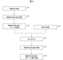
- FIG. 2 is a flow chart showing an example of a method for manufacturing the composite ceramics 1 according to this embodiment.
- the manufacturing method of the composite ceramics 1 according to this embodiment includes at least the following steps S1 to S4.
- a first raw material powder containing a garnet phosphor component 2, a nitride phosphor component 3, and a matrix component 4 is mixed (step S1 , mixing step).
- mixing the first raw material powder means mixing each component contained in the first raw material powder.
- the first raw material powder may contain the sintering aid.
- Dry mixing is used to mix the first raw material powder.
- any mixer may be used as long as powder mixing by a dry method is possible.
- step S2 first raw material powder accommodating step.
- step S3 the first raw material powder accommodated in the mold is sintered (step S3, sintering step).
- SPS discharge plasma sintering
- hot press method is used for sintering the first raw material powder.
- the SPS method and the hot press method are types of solid compression sintering methods, in which the first raw material powder accommodated in the mold is press-molded while being heated.
- the molded body is sintered by pulse electric heating while press-molding with mechanical pressure.
- electromagnetic energy due to pulse current, self-heating of the molded body, discharge plasma energy generated between each component, etc. are combined for sintering.
- the compact can be sintered.
- the SPS method it is possible to sinter by heating to a high temperature in a short period of time while applying mechanical pressure. can be sintered into a sintered body in which each component contained in is bonded at high density and substantially uniformly. In addition, since the SPS method requires a short sintering time, grain growth of each component can be suppressed.
- the hot press method sintering is performed in a pressurized atmosphere as in the SPS method.
- the sintering time is longer than that of the SPS method.
- the hot press method is excellent in mass productivity.
- the sintering temperature in the sintering step is preferably 1000°C or higher and 2000°C or lower. By setting the sintering temperature to 2000° C. or less, the sintering temperature is not too high, and it is possible to suppress the formation of oxides and the solid solution of the above components to form new compounds. Without losing the characteristics of each component.
- the sintering temperature is not too low, and the primary particles of the above components are likely to be in a bonded state.
- the components described above are mixed without solid solution, and a structure in which adjacent phases adhere to each other is likely to be formed. For this reason, for example, it becomes easy to obtain the composite ceramics 1 that has a sufficient processing strength as a bulk body and that outputs a suitable incandescent fluorescent light.
- the sintering time in the sintering step is not particularly limited, and may be any time from 5 minutes to 20 hours, for example.
- step S4 mold release step
- the method for manufacturing the composite ceramics 1 may further include an annealing step (step S5) for annealing the sintered body obtained in the sintering step after the releasing step.
- the annealing temperature is preferably 800°C or higher and 1500°C or lower, for example.
- the annealing time is not particularly limited, and may be any time from 5 minutes to 20 hours, for example.
- Annealing is preferably performed in a reducing atmosphere such as an N2 atmosphere or an H2 and N2 atmosphere.
- the method for manufacturing the composite ceramics 1 may further include a cutting/polishing step (step S6) in which at least one of cutting and polishing is applied to the sintered body.
- the size of the composite ceramics 1 is not particularly limited, and the sintered body taken out from the mold in the mold release process can be used as the composite ceramics 1 as it is. However, in order to make the composite ceramics 1 of a predetermined size, the obtained sintered body may be subjected to at least one of cutting and polishing as described above.
- the method of cutting the sintered body is not particularly limited, and for example, the sintered body may be sliced (cut) with a wire saw or the like.
- a thin composite ceramic 1 can be obtained by cutting the sintered body.
- the thin composite ceramics 1 may be manufactured without cutting by using a thin mold or by adjusting the amount of the first raw material powder contained in the mold.
- the method for polishing the sintered body is not particularly limited.
- the surface of the sintered body may be polished by rotating the polishing unit while discharging the polishing liquid from the discharge unit of the polishing apparatus.
- the thickness of the sintered body can be reduced while the surface can be made smooth. Therefore, the composite ceramic 1 having a thin thickness and a smooth surface can be obtained by performing polishing.
- the present embodiment is not limited to this. Only one of the annealing process and the cutting/polishing process may be performed. Also, the annealing step may be performed after the cutting/polishing step.
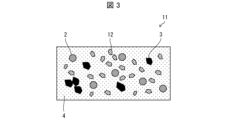
- FIG. 3 is a cross-sectional view showing an example of the structure of the composite ceramics 11 according to this embodiment.
- the composite ceramic 11 according to this embodiment has the same configuration as the composite ceramic 1 according to Embodiment 1, except that it further contains a light scattering component 12.
- the light scattering component 12 may be a light scatterer having a refractive index higher than that of the matrix component 4 by 0.21 or more.
- the composite ceramic further contains the light scattering component 12 in addition to the garnet phosphor component 2, the nitride phosphor component 3, and the matrix component 4, the sum of the matrix component 4 and the light scattering component 12 is
- the content is desirably 31 wt % or more and 95 wt % or less of the total components.
- the composite ceramics 11 which is excellent in light scattering properties and capable of efficiently extracting the generated fluorescence and excitation light to the outside.
- the light scattering component 12 includes, for example, at least one selected from the group consisting of AlN, cBN, SiC, AlN--SiC solid solution, and diamond. These light-scattering components are particularly excellent in light-scattering properties and can be suitably used as the light-scattering component 12 .
- the upper limit of the refractive index difference between the light scattering component 12 used in this embodiment and the matrix component 4 is not particularly limited. However, among MgO and Al 2 O 3 used for the matrix component 4, the refractive index of Al 2 O 3 having a low refractive index is 1.63. , the refractive index of SiC, which has the highest refractive index, is about 2.72. Therefore, when the above-exemplified light scattering component is used as the light scattering component 12, the maximum difference in refractive index between the light scattering component 12 and the matrix component 4 is 1.1.
- the number average particle diameter of the light scattering component 12 contained per unit volume of the composite ceramic 1 is preferably 0.25 ⁇ m or more and 40 ⁇ m or less, more preferably 0.5 ⁇ m or more and 20 ⁇ m or less.
- the number average particle size of the light scattering component 12 may be a value measured by SEM, or may be a specification described in a statement of delivery or a catalog. When the number average particle size of the light scattering component 12 is within the above range, light scattering is maximized by Mie scattering.
- the maximum light scattering effect can be obtained.
- the first raw material powder contains the raw material powder serving as the raw material of the light scattering component 12, so that the composite ceramics 11 can emit light. It contains a scattered component 12 . Therefore, the composite ceramics 11 can be manufactured by mixing the first raw material powder, which further contains the raw material powder of the light scattering component 12, in the mixing step (step S1).
- the composite ceramics 11 may also contain the sintering aid.
- FIG. 4 is a cross-sectional view showing an example of the structure of the composite ceramics 21 according to this embodiment.
- the composite ceramics 21 according to this embodiment has a laminated structure including a first ceramics layer 22 and a second ceramics layer 23 .
- the first ceramics layer 22 shown in FIG. 4 has the same configuration as the composite ceramics 1 according to the first embodiment.
- the second ceramic layer 23 is made of at least one selected from the group consisting of MgO and Al 2 O 3 and is bonded to one main surface of the first ceramic layer 22 .
- the second ceramic layer 23 having the above-described configuration is bonded onto the first ceramic layer 22, burning of the surface of the composite ceramic is suppressed even when strongly excited by laser light. can do. Therefore, according to the present embodiment, it is possible to provide the composite ceramic 12 capable of suppressing deterioration of the surface due to such scorching.
- the thickness of the first ceramics layer 22 is not particularly limited, and can be set to the same thickness as the composite ceramics 1 according to the first embodiment, for example.
- the thickness of the second ceramics layer 23 is not particularly limited, the second ceramics layer 23 does not contain a fluorescent component and does not contribute to fluorescence emission. It is desirable to be formed thinner than one ceramic layer 22 .
- the thickness of the second ceramics layer 23 is, for example, 30 ⁇ m or less.
- the thickness of the second ceramics layer 23 is desirably 1 ⁇ m or more, for example.
- the method of manufacturing the composite ceramics 21 is the same as the method of manufacturing the composite ceramics 1 according to the first embodiment, except for the following points.
- the method for manufacturing the composite ceramics 21 includes a step of accommodating a second raw material powder containing at least one selected from the group consisting of MgO and Al 2 O 3 and containing a second raw material powder less than the first raw material powder in a molding die. Including more.
- the first raw material powder and the second raw material powder accommodated in the molding die are sintered.
- a sintered body is formed in which the sintered body of the first raw material powder and the sintered body of the second raw material powder, which is thinner than the first raw material powder, are joined together.
- the composite ceramics 21 can be manufactured.
- the second raw powder containing step may be performed after the first raw powder containing step (step S2) (that is, between steps S2 and S3), and the first raw powder containing step ( It may be performed before step S2) (that is, between steps S1 and S2).
- the second raw powder containing step be performed twice before and after the first raw powder containing step.
- the step of accommodating the second raw material powder is performed twice before and after the step of accommodating the first raw material powder
- the second ceramic layer 23 is formed with the first ceramic layer 22 interposed therebetween after the mold release step (step S4).
- the second ceramic layer 23 on one main surface of the first ceramic layer 22 may be removed by grinding, polishing, or the like. Said removal may be performed in said cutting/polishing step.
- the sintered body is sliced (cut) so that one main surface of the first ceramic layer 22 has a second ceramic layer 23 on one main surface.
- a plurality of composite ceramics 21 having ceramic layers 23 formed thereon may be manufactured.
- the annealing process (step S5) may be performed as necessary.
- the composite ceramics 21 may also contain the sintering aid.
- the case where the first ceramic layer 22 has the same configuration as the composite ceramic 1 according to Embodiment 1 is illustrated as an example, but this embodiment is limited to this. not a thing
- the first ceramics layer 22 may have the same configuration as the composite ceramics 11 according to the second embodiment.
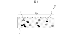
- FIG. 5 is a cross-sectional view showing an example of the structure of the composite ceramics 31 according to this embodiment.
- the composite ceramic 31 according to the present embodiment has, for example, the same configuration as the composite ceramic 1 according to the first embodiment, except that unevenness 31a is formed on one main surface. are doing.
- the method for manufacturing the composite ceramics 21 is the same as the method for manufacturing the composite ceramics 1 according to Embodiment 1, except that it further includes an unevenness forming step of forming unevennesses 31a on one main surface of the sintered body. is.
- the unevenness 31a is a dicer groove.
- this embodiment is not limited to this.
- the unevenness 31a may be formed by a dicer or laser processing, or the unevenness 31a may be formed by roughening the main surface by polishing.
- the composite ceramics 31 having the irregularities 31a formed on one main surface can scatter and efficiently extract the fluorescence and excitation light generated inside. be able to.
- the height of the unevenness 31a on the surface is not particularly limited as long as it can scatter the fluorescence and excitation light generated inside as described above.
- FIG. 5 shows an example in which the composite ceramics 31 has a structure in which unevenness 31 a is formed on one main surface of the composite ceramics 1 .
- the composite ceramics 31 according to this embodiment may have a structure in which one main surface of the composite ceramics 11 is formed with irregularities 31a.
- the composite ceramics 31 according to the present embodiment has a structure in which irregularities 31a are formed on the main surface of the second ceramics layer 23 of the composite ceramics 21 opposite to the first ceramics layer 22. good too.
- FIG. 6 shows a composite ceramic 1 provided with an AR (anti-reflection) coating film 41 on one main surface according to this embodiment.
- the AR coating film 41 is provided on the main surface of the composite ceramics 1, so that when the composite ceramics 1 is used as a phosphor element for laser illumination, excitation light is emitted on the irradiation surface of the excitation light. Light can be prevented from being reflected. Thereby, the loss of light when the excitation light is absorbed by the composite ceramics 1 can be reduced. Furthermore, fluorescence and scattered light generated in the phosphor of the composite ceramics 1 can be effectively extracted.
- a dielectric multilayer film such as SiO 2 , TiO 2 , Si 3 N 4 is used. These can be formed by a film forming method such as ion beam vapor deposition or sputtering.
- composite ceramics provided with the AR coating film 41 in this way may be referred to as composite ceramics with an AR coating film.
- Composite ceramics with an AR coating film that has been AR-coated in this manner is suitably used, for example, as a phosphor element for laser illumination.
- FIG. 7 is a cross-sectional view showing an example of the phosphor element 50 according to this embodiment.
- the phosphor element 50 shown in FIG. 7 includes the composite ceramics 1 provided with the AR coating film 41, the substrate 51, the adhesive layer 52, and the mirror 53 shown in FIG.
- the base material 51 is a supporting member that supports the composite ceramics 1 .
- Composite ceramics 1 is fixed on substrate 51 .
- the base material 51 is not particularly limited as long as the composite ceramics 1 can be fixed.
- the base material 51 includes metals such as SUS, Al, Cu, Mo, Ag, W, and the like. When the base material 51 is made of these metals, it can suitably reflect excitation light emitted from an excitation light source such as a laser light source.
- the phosphor element 50 having excellent thermal conductivity can be obtained.
- substrate 51 is not limited to such a non-transmissive substrate.
- substrate 51 may be a transmissive substrate such as, for example, monocrystalline sapphire or polycrystalline alumina, denoted Al 2 O 3 .
- the composite ceramic 1 is fixed to the base material 51 so that the AR coat film 41 is positioned on the main surface opposite to the base material 51, as shown in FIG.
- the mirror 53 is a reflector (mirror body) that reflects the light transmitted through the composite ceramics 1 .
- the mirror 53 is provided on the main surface of the composite ceramics 1 on the substrate 51 side.
- the main surface of the composite ceramic 1 on the substrate 51 side may be referred to as the "back main surface”
- the main surface on the opposite side of the substrate 51 may be referred to as the "front main surface”.
- the mirror 53 is provided on the back main surface side of the composite ceramics 1, and the AR coat film 41 is provided on the front main surface side of the composite ceramics.
- the mirror 53 is provided on the back main surface side of the composite ceramics 1 in this way, when the excitation light is applied to the front main surface side of the composite ceramics 1, the light transmitted through the composite ceramics 1 is reflected by the mirror 53. can be reflected. Thereby, the utilization efficiency of light can be improved.
- the mirror 53 is not particularly limited as long as it can reflect the light transmitted through the composite ceramics 1.
- a silver-based mirror containing silver or a silver alloy, which is a specular reflection positive material, is preferably used.
- the adhesive layer 52 is a layer that bonds the composite ceramics 1 provided with the mirror 53 and the base material 51 .
- the adhesive material used for the adhesive layer 52 is not particularly limited as long as it can adhere the composite ceramics 1 provided with the mirror 53 and the base material 51 .
- Examples of the adhesive material include silver-based or silver-alloy based inorganic adhesives.
- FIG. 8 is a flow chart showing an example of a method for manufacturing the phosphor element 50 shown in FIG.
- a cutting step (step S11) of cutting the sintered body, and a back main surface of the sintered body A back main surface polishing step (step S12) is performed.
- the cutting/grinding step is not essential.
- step S13 a film of the mirror 53 is formed on the back main surface of the sintered body (step S13, mirror film forming step).
- step S13 mirror film forming step
- the substrate 51 is prepared (step S21, substrate preparation step).
- step S13 the base material 51 and the mirror-equipped composite ceramics obtained in step S13 are bonded together with an adhesive material forming the adhesive layer 52 (step S14, bonding step).
- step S15 front main surface polishing step
- step S16 AR coat film formation step
- the front main surface polishing process is performed after the bonding process, but the present embodiment is not limited to this.
- the front and main surface polishing step may be performed before the bonding step.
- the phosphor element 50 is not limited to the structure shown in FIG.
- the phosphor element 50 may include, for example, the composite ceramics 1 and a substrate 51 to which the composite ceramics 1 is fixed.
- the composite ceramics 1 instead of the composite ceramics 1, the composite ceramics 11, the composite ceramics 21, or the composite ceramics 31 may be provided. Composite ceramics obtained by combining them may also be used.
- composite ceramics can be suitably used for phosphor elements for laser illumination (in other words, phosphor elements for laser illumination devices).
- the laser illumination device includes a phosphor element, a laser light source that irradiates excitation light to the composite ceramics in the phosphor element, and a condensing member that collects the light output from the composite ceramics in the phosphor element ( (first condensing member).
- FIG. 9 is a cross-sectional view showing an example of a laser illumination device 60 according to this embodiment.
- a laser illumination device 60 shown in FIG. 9 includes, for example, a phosphor element 50 shown in FIG. 8 as an example of the phosphor element.
- a laser illumination device 60 shown in FIG. 9 includes a laser light source 61 as the laser light source and a lens 63 as the first condensing member.
- the laser illumination device 60 shown in FIG. 9 includes a lens 62 as a second condensing member for condensing the excitation light output from the laser light source 61 .
- the laser light source 61 irradiates the composite ceramics 1 in the phosphor element 50 with the excitation light L1 as the first light through the lens 62 .
- the excitation light L1 output from the laser light source 61 is condensed by the lens 62, and the lens 62
- the composite ceramics 1 in the phosphor element 50 is irradiated with the light from above.
- the composite ceramic 1 absorbs at least part of the excitation light L1' and outputs second light including light with a wavelength different from the excitation light L1' (that is, light with a wavelength different from the excitation light L1).
- the garnet phosphor component 2 described above emits, for example, yellow fluorescence Y by the blue light that is the excitation light L1
- the nitride phosphor component 3 emits red fluorescence by the blue light that is the excitation light L1. Emit R.
- these phosphors scatter the blue light that does not contribute to the excitation in the blue light that is the excitation light L1, and transmits it as blue scattered light B. As shown in FIG.
- the phosphor element 50 may include the composite ceramics according to the present disclosure and the substrate 51 as described in the fifth embodiment.
- the composite ceramic may be the composite ceramic described in any one of Embodiments 1 to 4, or may be a composite ceramic obtained by combining them.
- the laser light source 61 is not particularly limited as long as it can irradiate the excitation light L1.
- a blue semiconductor LD LD: laser diode
- irradiates blue light as the excitation light L1 as described above can be cited. be done.
- the phosphor element 50 When the phosphor element 50 includes the mirror 52 as described above, or when the base material 51 is a non-transmissive base material that does not transmit the excitation light L1, the phosphor element 50 is positioned on the side of the emitted light of the laser light source 61. It is arranged so that the composite ceramics 1 is positioned.
- the base material 51 is a transmissive base material and does not have a reflector such as the mirror 52 on the back main surface side of the composite ceramics 1, the side of the base material 51 opposite to the fixed surface of the composite ceramics 1
- the excitation light L1 is irradiated from the surface of .
- the second light is emitted from the front main surface side of the composite ceramics 1 .
- both the first light collecting member and the second light collecting member are lenses
- these condensing members may be lenses or mirrors.
- Example 1 As shown in FIG. 10, in Example 1, the contents of YAG as a garnet-based phosphor component, Sr 2 Si 5 N 8 as a nitride-based phosphor component, and Al 2 O 3 as a matrix component were However, each raw material powder was mixed so as to be 25 wt %, 25 wt %, and 50 wt %, respectively.
- this raw material powder was filled into a mold and sintered at 1350°C for 3 minutes in a nitrogen atmosphere using the SPS method to produce composite ceramics.
- the laser power dependence of the fluorescence power of the resulting composite ceramics was measured using a phosphor evaluation device equipped with a laser light source, an integrating sphere, and a spectroscope.
- the excitation laser beam in the laser light source had a diameter of 1 mm, an excitation laser wavelength of 450 nm, and a continuous excitation laser beam. The results are shown in FIG.
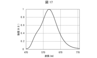
- the obtained composite ceramics was irradiated with excitation light from a laser light source, and the fluorescence spectrum of the beam output from the composite ceramics through a lens was measured using a fluorescence spectroscope. More specifically, using a spectroscope manufactured by Ocean Photonics Co., Ltd., the emission spectrum was measured under room temperature conditions with the excitation wavelength fixed at 441 nm. The results are shown in FIG.
- Example 2 As shown in FIG . 10, in Example 2, each raw material powder was mixed so that the contents of YAG, Sr2Si5N8 , and Al2O3 were 15 wt%, 15 wt%, and 70 wt%, respectively. Mixed. Except for this point, in Example 2, the same operation as in Example 1 was performed to produce a composite ceramic.
- Example 2 the same phosphor evaluation device as in Example 1 was used to measure the laser power dependence of the fluorescence power of the obtained composite ceramics. The results are shown in FIG.
- Example 2 Using the same device as in Example 1, the fluorescence spectrum of the beam output from the composite ceramics through the lens was measured using the same fluorescence spectrometer as in Example 1. The results are shown in FIG.
- Example 3 As shown in FIG. 10, in Example 3, each raw material powder was mixed so that the contents of YAG, Sr2Si5N8 , and Al2O3 were 5 wt%, 5 wt%, and 90 wt % , respectively. Mixed and sintered at 1300°C. Except for this point, in Example 3, the same operation as in Example 1 was performed to produce a composite ceramic.
- Example 2 the same phosphor evaluation device as in Example 1 was used to measure the laser power dependence of the fluorescence power of the obtained composite ceramics. The results are shown in FIG.
- Example 2 the fluorescence spectrum of the beam output from the composite ceramics through the lens was measured using the same fluorescence spectrometer as in Example 1. The results are shown in FIG.
- Comparative Example 1 As shown in FIG. 10, in Comparative Example 1, only Sr 2 Si 5 N 8 was filled in the mold and sintered at 1800°C. Except for this point, in Comparative Example 1, the same operation as in Example 1 was performed to produce a composite ceramic for comparison.
- Example 2 the same phosphor evaluation device as in Example 1 was used to measure the laser power dependence of the fluorescence power of the obtained composite ceramics. This result is shown in FIG.
- Example 2 Using the same device as in Example 1, the fluorescence spectrum of the beam output from the composite ceramics through the lens was measured using the same fluorescence spectrometer as in Example 1. The results are shown in FIG.
- Example 4 As shown in FIG. 22, in Example 4 , MgO was used instead of Al2O3 , and the contents of YAG, Sr2Si5N8 , and MgO were 15 wt%, 15 wt% , and 70 wt%, respectively. %, and sintered at 1300°C. Except for this point, in Example 4, the same operation as in Example 1 was performed to produce a composite ceramic.
- Example 2 the same phosphor evaluation device as in Example 1 was used to measure the laser power dependence of the fluorescence power of the obtained composite ceramics. The results are shown in FIG.
- Example 2 Using the same device as in Example 1, the fluorescence spectrum of the beam output from the composite ceramics through the lens was measured using the same fluorescence spectrometer as in Example 1. The results are shown in FIG.
- Example 5 As shown in FIG. 22, in Example 5, about 10% of MgO was changed to AlN as a light scattering component, and the contents of YAG, Sr2Si5N8 , MgO, and AlN were each 15 wt. %, 15 wt %, 63 wt %, and 7 wt %. Except for this point, in Example 5, the same operation as in Example 1 was performed to produce a composite ceramic.
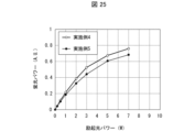
- Example 4 the same phosphor evaluation device as in Example 1 was used to measure the laser power dependence of the fluorescence power of the obtained composite ceramics. This result is shown in FIG. 23 together with the laser power dependence of the fluorescence power of the composite ceramics obtained in Example 4.
- the SEM image shown in FIG. 14 is a backscattered electron image, in which the portions composed of heavy elements appear white and the portions composed of light elements appear dark. Moreover, the shape of each component is a shape corresponding to the shape of the raw material particles. From the results shown in FIG . 14, the obtained composite ceramic contains YAG, Sr2Si5N8 , and Al2O3 , and Al2O3 surrounds YAG and Sr2Si5N8 . It was confirmed that it was sintered.
- the nitride-based phosphor component Sr 2 Si 5 N 8 is an oxide matrix component such as Al 2 O 3 I was able to confirm that there were still some left.
- the nitride phosphor has low excitation light power resistance (laser power resistance), and the garnet phosphor component and the matrix component are low. It can be seen that the pumping light power resistance is greatly improved by the addition.
- the fluorescent power was improved by about 10% or more by including, for example, AlN having a high refractive index as a light scattering component as part of the matrix component.
Abstract
La présente invention concerne une céramique composite (1) qui comprend un comprimé fritté contenant : un constituant du luminophore de type grenat (2) ; un constituant du luminophore de type nitrure (3) ; et un constituant de la matrice (4) comprenant au moins un élément choisi dans le groupe constitué par MgO et Al2O3. Le rapport de teneur du constituant de la matrice est de 31 % en poids à 95 % en poids par rapport aux constituants totaux. Le frittage est effectué avec le constituant de la matrice disposé de manière à renfermer le constituant du luminophore de type grenat et le constituant du luminophore de type nitrure.
Priority Applications (2)
| Application Number | Priority Date | Filing Date | Title |
|---|---|---|---|
| PCT/JP2022/009002 WO2023166638A1 (fr) | 2022-03-02 | 2022-03-02 | Céramique composite, élément luminophore, dispositif d'éclairage laser et procédé de fabrication d'élément composite |
| PCT/JP2023/007928 WO2023167306A1 (fr) | 2022-03-02 | 2023-03-02 | Céramique composite, élément de phosphore, dispositif d'éclairage laser et procédé de production de céramique composite |
Applications Claiming Priority (1)
| Application Number | Priority Date | Filing Date | Title |
|---|---|---|---|
| PCT/JP2022/009002 WO2023166638A1 (fr) | 2022-03-02 | 2022-03-02 | Céramique composite, élément luminophore, dispositif d'éclairage laser et procédé de fabrication d'élément composite |
Publications (1)
| Publication Number | Publication Date |
|---|---|
| WO2023166638A1 true WO2023166638A1 (fr) | 2023-09-07 |
Family
ID=87883252
Family Applications (2)
| Application Number | Title | Priority Date | Filing Date |
|---|---|---|---|
| PCT/JP2022/009002 WO2023166638A1 (fr) | 2022-03-02 | 2022-03-02 | Céramique composite, élément luminophore, dispositif d'éclairage laser et procédé de fabrication d'élément composite |
| PCT/JP2023/007928 WO2023167306A1 (fr) | 2022-03-02 | 2023-03-02 | Céramique composite, élément de phosphore, dispositif d'éclairage laser et procédé de production de céramique composite |
Family Applications After (1)
| Application Number | Title | Priority Date | Filing Date |
|---|---|---|---|
| PCT/JP2023/007928 WO2023167306A1 (fr) | 2022-03-02 | 2023-03-02 | Céramique composite, élément de phosphore, dispositif d'éclairage laser et procédé de production de céramique composite |
Country Status (1)
| Country | Link |
|---|---|
| WO (2) | WO2023166638A1 (fr) |
Citations (5)
| Publication number | Priority date | Publication date | Assignee | Title |
|---|---|---|---|---|
| JP2011012215A (ja) * | 2009-07-03 | 2011-01-20 | Covalent Materials Corp | セラミックス複合体 |
| JP2016180076A (ja) * | 2015-03-25 | 2016-10-13 | 日亜化学工業株式会社 | 蛍光物質成形体の製造方法、発光装置 |
| JP2020096022A (ja) * | 2018-12-10 | 2020-06-18 | 日亜化学工業株式会社 | 発光装置及びその製造方法 |
| JP2022007638A (ja) * | 2020-06-26 | 2022-01-13 | 日亜化学工業株式会社 | 成形体、発光装置及び成形体の製造方法 |
| JP2022036059A (ja) * | 2020-08-19 | 2022-03-04 | 国立大学法人大阪大学 | コンポジットセラミックス蛍光体およびコンポジットセラミックス蛍光体の製造方法 |
-
2022
- 2022-03-02 WO PCT/JP2022/009002 patent/WO2023166638A1/fr unknown
-
2023
- 2023-03-02 WO PCT/JP2023/007928 patent/WO2023167306A1/fr unknown
Patent Citations (5)
| Publication number | Priority date | Publication date | Assignee | Title |
|---|---|---|---|---|
| JP2011012215A (ja) * | 2009-07-03 | 2011-01-20 | Covalent Materials Corp | セラミックス複合体 |
| JP2016180076A (ja) * | 2015-03-25 | 2016-10-13 | 日亜化学工業株式会社 | 蛍光物質成形体の製造方法、発光装置 |
| JP2020096022A (ja) * | 2018-12-10 | 2020-06-18 | 日亜化学工業株式会社 | 発光装置及びその製造方法 |
| JP2022007638A (ja) * | 2020-06-26 | 2022-01-13 | 日亜化学工業株式会社 | 成形体、発光装置及び成形体の製造方法 |
| JP2022036059A (ja) * | 2020-08-19 | 2022-03-04 | 国立大学法人大阪大学 | コンポジットセラミックス蛍光体およびコンポジットセラミックス蛍光体の製造方法 |
Also Published As
| Publication number | Publication date |
|---|---|
| WO2023167306A1 (fr) | 2023-09-07 |
Similar Documents
| Publication | Publication Date | Title |
|---|---|---|
| US8872208B2 (en) | Light source device and lighting device | |
| JP5530165B2 (ja) | 光源装置および照明装置 | |
| US9519207B2 (en) | Wavelength converting device and light emitting device using the same | |
| JP5347354B2 (ja) | 蛍光物質成形体及びその製造方法、発光装置 | |
| CN110720060B (zh) | 波长转换体和其制造方法以及使用了波长转换体的发光装置 | |
| JP5611690B2 (ja) | 光源装置、色調整方法、照明装置 | |
| JP2010509764A (ja) | モノリシックセラミック発光変換体を含む照明システム | |
| JP6544408B2 (ja) | 光学部品及び光学部品の製造方法 | |
| JP2012104267A (ja) | 光源装置および照明装置 | |
| US10591137B2 (en) | Wavelength converter and light-emitting device having same | |
| JP2012036367A (ja) | 蛍光体複合部材 | |
| JP2006173433A (ja) | 光変換用セラミック複合体およびそれを用いた発光装置 | |
| TW201920608A (zh) | 光波長轉換裝置及光複合裝置 | |
| JP2012243618A (ja) | 光源装置および照明装置 | |
| CN113583675A (zh) | 激光激发金属衬底荧光膜、荧光转换模块及制备方法和应用 | |
| WO2012008306A1 (fr) | Elément composite au phosphore, indicateur à diodes électroluminescentes et procédé de fabrication de l'élément composite au phosphore | |
| US11069841B2 (en) | Multilayer ceramic converter with stratified scattering | |
| JP5781367B2 (ja) | 光源装置および照明装置 | |
| WO2023166638A1 (fr) | Céramique composite, élément luminophore, dispositif d'éclairage laser et procédé de fabrication d'élément composite | |
| JP2006169422A (ja) | 光変換用セラミック複合体およびそれを用いた発光装置 | |
| JP5766521B2 (ja) | 照明装置 | |
| WO2019021846A1 (fr) | Élément de conversion de longueur d'onde et dispositif électroluminescent | |
| JP2022036059A (ja) | コンポジットセラミックス蛍光体およびコンポジットセラミックス蛍光体の製造方法 | |
| JP7147138B2 (ja) | 発光装置、照明装置、画像表示装置及び車両表示灯 | |
| CN216818372U (zh) | 一种荧光转换复合层及白光发光器件 |
Legal Events
| Date | Code | Title | Description |
|---|---|---|---|
| 121 | Ep: the epo has been informed by wipo that ep was designated in this application |
Ref document number: 22929783 Country of ref document: EP Kind code of ref document: A1 |