WO2023166638A1 - Composite ceramic, phosphor element, laser illumination device, and method for manufacturing composite element - Google Patents
Composite ceramic, phosphor element, laser illumination device, and method for manufacturing composite element Download PDFInfo
- Publication number
- WO2023166638A1 WO2023166638A1 PCT/JP2022/009002 JP2022009002W WO2023166638A1 WO 2023166638 A1 WO2023166638 A1 WO 2023166638A1 JP 2022009002 W JP2022009002 W JP 2022009002W WO 2023166638 A1 WO2023166638 A1 WO 2023166638A1
- Authority
- WO
- WIPO (PCT)
- Prior art keywords
- component
- composite ceramics
- phosphor
- nitride
- composite
- Prior art date
Links
Images


Classifications
-
- C—CHEMISTRY; METALLURGY
- C09—DYES; PAINTS; POLISHES; NATURAL RESINS; ADHESIVES; COMPOSITIONS NOT OTHERWISE PROVIDED FOR; APPLICATIONS OF MATERIALS NOT OTHERWISE PROVIDED FOR
- C09K—MATERIALS FOR MISCELLANEOUS APPLICATIONS, NOT PROVIDED FOR ELSEWHERE
- C09K11/00—Luminescent, e.g. electroluminescent, chemiluminescent materials
- C09K11/08—Luminescent, e.g. electroluminescent, chemiluminescent materials containing inorganic luminescent materials
- C09K11/55—Luminescent, e.g. electroluminescent, chemiluminescent materials containing inorganic luminescent materials containing beryllium, magnesium, alkali metals or alkaline earth metals
-
- C—CHEMISTRY; METALLURGY
- C09—DYES; PAINTS; POLISHES; NATURAL RESINS; ADHESIVES; COMPOSITIONS NOT OTHERWISE PROVIDED FOR; APPLICATIONS OF MATERIALS NOT OTHERWISE PROVIDED FOR
- C09K—MATERIALS FOR MISCELLANEOUS APPLICATIONS, NOT PROVIDED FOR ELSEWHERE
- C09K11/00—Luminescent, e.g. electroluminescent, chemiluminescent materials
- C09K11/08—Luminescent, e.g. electroluminescent, chemiluminescent materials containing inorganic luminescent materials
- C09K11/59—Luminescent, e.g. electroluminescent, chemiluminescent materials containing inorganic luminescent materials containing silicon
-
- C—CHEMISTRY; METALLURGY
- C09—DYES; PAINTS; POLISHES; NATURAL RESINS; ADHESIVES; COMPOSITIONS NOT OTHERWISE PROVIDED FOR; APPLICATIONS OF MATERIALS NOT OTHERWISE PROVIDED FOR
- C09K—MATERIALS FOR MISCELLANEOUS APPLICATIONS, NOT PROVIDED FOR ELSEWHERE
- C09K11/00—Luminescent, e.g. electroluminescent, chemiluminescent materials
- C09K11/08—Luminescent, e.g. electroluminescent, chemiluminescent materials containing inorganic luminescent materials
- C09K11/64—Luminescent, e.g. electroluminescent, chemiluminescent materials containing inorganic luminescent materials containing aluminium
Definitions
- the present disclosure relates to composite ceramics containing a garnet-based phosphor component, a nitride-based phosphor component, and a matrix component, a phosphor element and a laser illumination device having the same, and a method for manufacturing the composite ceramics.
- Laser lighting devices are more energy efficient, compact, and brighter than other lighting devices, and have already begun to be put into practical use as lighting devices for projectors and automobile headlights. Also, in the home lighting market, replacement of existing LED (light emitting diode) lighting devices and fluorescent lamps with laser lighting devices is expected, and the laser lighting market is expected to expand rapidly in the future.
- LED light emitting diode
- Patent Document 1 discloses, as composite ceramics, ceramics containing a phosphor phase made of YAG containing Ce, a matrix phase made of at least one of Al 2 O 3 and AlN, and impurities within a predetermined range. A composite is disclosed.
- Patent Document 2 As a composite ceramic, a fluorescent substance molded body is produced by sintering a mixture of AlN powder and phosphor powder by a discharge plasma sintering method, melting the AlN powder, and then cooling it. is disclosed.
- the red phosphor means a phosphor that emits red to orange light.
- Patent Document 2 discloses that a nitride-based phosphor may be used as the phosphor powder.
- a composite ceramic according to one aspect of the present disclosure is a composite ceramic made of a sintered body containing a garnet phosphor component, a nitride phosphor component, and a matrix component, , the matrix component is at least one selected from the group consisting of MgO and Al 2 O 3 , the content of the matrix component is in the range of 31 wt% or more and 95 wt% or less of the total components, and the matrix component surrounds the garnet-based phosphor component and the nitride-based phosphor component and is sintered.
- a phosphor element according to one aspect of the present disclosure includes composite ceramics according to one aspect of the present disclosure, and a base material for fixing the composite ceramics.
- a laser illumination device includes a phosphor element according to one aspect of the present disclosure, and a laser light source that irradiates the composite ceramics in the phosphor element with excitation light. and a condensing member condensing light output from the composite ceramics in the phosphor element.
- a method for manufacturing a composite ceramic mixes a first raw material powder containing a garnet-based phosphor component, a nitride-based phosphor component, and a matrix component.
- a composite ceramic containing a red phosphor for laser illumination which can be produced relatively easily, a phosphor element and a laser illumination device including the same, and the It is possible to provide a method for producing such composite ceramics.
- FIG. 1 is a cross-sectional view showing an example of the structure of composite ceramics according to Embodiment 1.
- FIG. 3 is a flow chart showing an example of a method for manufacturing composite ceramics according to Embodiment 1.
- FIG. FIG. 5 is a cross-sectional view showing an example of the structure of composite ceramics according to Embodiment 2;
- FIG. 10 is a cross-sectional view showing an example of the structure of composite ceramics according to Embodiment 3;
- FIG. 10 is a cross-sectional view showing an example of the structure of composite ceramics according to Embodiment 4;
- FIG. 10 is a diagram showing a composite ceramic having one main surface provided with an antireflection coating film according to Embodiment 5;
- FIG. 11 is a cross-sectional view showing an example of a phosphor element according to Embodiment 5; 8 is a flow chart showing an example of a method for manufacturing the phosphor element shown in FIG. 7.
- FIG. FIG. 12 is a cross-sectional view showing an example of a laser illumination device according to Embodiment 6; 3 is a ternary diagram showing the contents of nitride-based phosphor components, matrix components, and garnet-based phosphor components in Examples 1 to 3 and Comparative Example 1.
- FIG. 1 is a diagram showing an XRD pattern of composite ceramics obtained in Example 1.
- FIG. 1 is a graph showing laser power dependence of fluorescence power of composite ceramics obtained in Example 1.
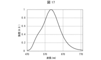
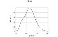
- FIG. 1 is a diagram showing fluorescence spectra of composite ceramics obtained in Example 1.
- FIG. FIG. 10 is a diagram showing an example of a SEM image of composite ceramics obtained in Example 2; 3 is a diagram showing an XRD pattern of composite ceramics obtained in Example 2.
- FIG. FIG. 4 is a graph showing laser power dependence of the fluorescence power of composite ceramics obtained in Example 2.
- FIG. 4 is a diagram showing fluorescence spectra of composite ceramics obtained in Example 2.
- FIG. 10 is a graph showing laser power dependence of the fluorescence power of composite ceramics obtained in Example 3.
- FIG. 10 is a diagram showing fluorescence spectra of composite ceramics obtained in Example 3; 4 is a graph showing laser power dependence of fluorescence power of composite ceramics obtained in Comparative Example 1.
- FIG. 2 is a diagram showing fluorescence spectra of composite ceramics obtained in Comparative Example 1.
- FIG. FIG. 10 is a ternary diagram showing the contents of nitride-based phosphor components, matrix components, and garnet-based phosphor components in Examples 4 and 5;
- FIG. 10 is a graph showing laser power dependence of the fluorescence power of composite ceramics obtained in Example 4.
- FIG. FIG. 10 is a diagram showing fluorescence spectra of composite ceramics obtained in Example 4;
- FIG. 10 is a graph showing laser power dependence of fluorescence power of composite ceramics obtained in Examples 4 and 5;
- FIG. 1 is a cross-sectional view showing an example of the structure of a composite ceramic 1 according to this embodiment.
- the composite ceramic 1 according to this embodiment is a multi-wavelength luminescent ceramic composite made of a sintered body containing phosphor components having two or more emission wavelengths and a matrix component.
- the composite ceramic 1 shown in FIG. 1 includes a garnet-based phosphor component 2, a nitride-based phosphor component 3, and a matrix component 4, and the matrix component 4 includes the garnet-based phosphor component 2 and the nitride-based phosphor. It has a sintered structure surrounding component 3.
- the composite ceramic 1 has a sea-island structure in which the garnet-based phosphor component 2 and the nitride-based phosphor component 3 are mixed in islands in the matrix component 4 . That is, the composite ceramic 1 has a structure in which the garnet-based phosphor component 2 and the nitride-based phosphor component 3 are dispersed like islands in a relatively continuous sea-like matrix component 4 . A matrix component 4 is filled between the garnet phosphor component 2 and the nitride phosphor component 3 .
- the garnet-based phosphor component 2, the nitride-based phosphor component 3, and the matrix component 4 are adhered to each other.
- the composite ceramic 1 comprises at least three phases of a first phosphor phase comprising a garnet phosphor component 2, a second phosphor phase comprising a nitride phosphor component 3, and a matrix phase comprising a matrix component 4. have phases.
- the composite ceramic 1 has a structure in which at least the above three phases are mixed and phases adjacent to each other are fixed.
- the structure in which at least the above three phases are mixed and the phases adjacent to each other are fixed means that the above three phases are not solid-dissolved, but are separated into regions of each phase in the solid, and the phases adjacent to each other are separated. A sticking structure is shown. It also includes the case where sintering aids and impurities are present at grain boundaries. Alternatively, even if there are slight alteration phases or melting phases between particles, if they basically have a solid three-phase structure, they are considered composite ceramics.
- Composite ceramics 1 excludes joints in which three or more phases are simply directly joined, and compositions in which at least the three phases are solidified by at least one of inorganic glass and organic binder.
- the garnet-based phosphor component 2 indicates a phosphor having a garnet crystal structure.
- the garnet-based phosphor component 2 is a phosphor having a large refractive index and excellent fluorescence characteristics, and emits yellowish to greenish yellowish fluorescence, for example, by blue excitation light.
- the light that does not contribute to the excitation among the excitation light is scattered and transmitted. Therefore, the garnet-based phosphor component 2 outputs blue scattered light and yellowish fluorescence.
- the garnet-based phosphor component 2 has excellent heat resistance, and can suppress deterioration even when irradiated with, for example, a high-power excitation light LD (laser diode).
- a high-power excitation light LD laser diode
- a YAG (yttrium-aluminum-garnet)-based phosphor can be used as the garnet-based phosphor component 2.
- the YAG-based phosphor indicates a phosphor that can be attributed to the crystal structure of the YAG phosphor.
- YAG phosphors examples include (Ce, Y) 3 Al 5 O 12 , (Ce, Lu) 3 Al 5 O 12 , (Ce, Lu, Y) 3 Al 5 O 12 , (Ce, Lu, Y ) 3 (Al, Ga) 5 O 12 .
- the YAG phosphor as the garnet phosphor component 2 in the composite ceramic 1, it is possible to easily realize the composite ceramic 1 that outputs yellowish to greenish yellow fluorescence.
- the composite ceramics 1 contains the YAG-based phosphor as the garnet-based phosphor component 2, the composite ceramics 1 having more excellent fluorescence characteristics can be obtained.
- the nitride-based phosphor component 3 indicates a phosphor containing nitrogen.
- Specific examples of the nitride phosphor component 3 include at least one phosphor selected from the group consisting of nitride phosphors and oxynitride phosphors.
- the nitride-based phosphor component 3 is a red-based phosphor that emits red-to-orange red-based fluorescence with excellent fluorescence properties. For example, it emits red-based fluorescence with blue excitation light. In addition, the light that does not contribute to the excitation among the excitation light is scattered and transmitted. Therefore, the nitride phosphor component 3 outputs blue scattered light and red fluorescence.
- the composite ceramic 1 contains the nitride-based phosphor component 3, the composite ceramic 1 having more excellent fluorescence characteristics can be obtained.
- nitride-based phosphor component 3 examples include Sr 2 Si 5 N 8 , (Sr, Ba) 2 Si 5 N 8 , (Ca, Sr, Ba) at least one nitride phosphor selected from the group consisting of 2Si5N8 .
- these nitride phosphors may be referred to as nitride phosphor (A).
- Eu and Ce are activators and are doped in the crystal.
- nitride- based phosphor component 3 for example, Eu:Sr2Si5N8, Eu:(Sr,Ba)2Si5N8 , Eu : ( Ca , Sr , Ba) 2Si5 N 8 , Ce: Sr 2 Si 5 N 8 , Ce: (Sr, Ba) 2 Si 5 N 8 , Ce: (Ca, Sr, Ba) Si 5 N 8 , (Eu, Ce): Sr 2 Si 5 N 8 , (Eu, Ce): (Sr, Ba) 2 Si 5 N 8 , (Eu, Ce): (Ca, Sr, Ba) 2 Si 5 N 8 and other nitride phosphors (A).
- the composite ceramic 1 that emits stable reddish fluorescence can be produced.
- nitride phosphors At least one of part of Si and part of N in the above composition formula may be substituted.
- Si When part of Si is substituted, Si is substituted with Al.
- N is replaced with O when part of N is replaced.
- the nitride-based phosphor component 3 is Sr 2 Si 5 N 8 , (Sr, Ba) 2 Si 5 N 8 , or (Ca, Sr, Ba) 2 Si 5 N 8 , in which part of Si is Al It may be a nitride phosphor in which N is substituted with or an oxynitride phosphor in which a part of N is replaced with O. Further, an oxynitride phosphor in which part of Si is replaced with Al and part of N is replaced with O may be used. As an example, for example, for example, (Sr, Ba) 2 (Si, Al) 5 N 8 , (Sr, Ba) 2 (Si, Al) 5 (N, O ) 8 and the like.
- nitride-based phosphor component 3 By including at least one of such a nitride phosphor and an oxynitride phosphor as the nitride-based phosphor component 3 in the composite ceramic 1, a more reliable composite ceramic 1 can be realized.
- the nitride-based phosphor component 3 is, for example, at least one nitride phosphor selected from the group consisting of CaAlSiN 3 and (Ca, Sr)AlSiN 3 activated with at least one element of Eu and Ce, respectively. It can be a body.
- these nitride phosphors may be referred to as nitride phosphor (B).
- Eu and Ce are activators and are doped in the crystal.
- the nitride-based phosphor component 3 includes, for example, Eu:CaAlSiN 3 , Eu:(Ca,Sr)AlSiN 3 , Ce:CaAlSiN 3 , Ce:(Ca,Sr)AlSiN 3 , (Eu, Ce ): CaAlSiN 3 , (Eu, Ce): (Ca, Sr) AlSiN 3 and other nitride phosphors (B).
- nitride-based phosphor component 3 in addition to the nitride phosphor (A) and the nitride phosphor (B), for example, Ce-activated (La, Y) 3 Si 6 N 11 , etc. There may be.
- nitride phosphors (A) and nitride phosphors (B), and nitride phosphors other than these nitride phosphors (A) and nitride phosphors (B) may be used separately. They may be used together as long as they do not dissolve or react with each other.
- Matrix component 4 is at least one selected from the group consisting of MgO (magnesium oxide) and Al 2 O 3 (aluminum oxide).
- the matrix component 4 may be MgO, Al 2 O 3 , or a mixture of MgO and Al 2 O 3 .
- the composite ceramic 1 according to this embodiment has an excitation light power resistance of 0.5 kW/cm 2 or more.
- the composite ceramic 1 according to the present embodiment is a composite ceramic for low color temperature, which has a high fluorescence power with respect to the excitation light power, can withstand laser excitation, and has a high excitation light power resistance. Therefore, according to this embodiment, it is possible to realize a phosphor element for a laser that is practical and does not saturate fluorescence even at relatively high power.
- the upper limit is not particularly limited.
- the upper limit of the pumping light power resistance is 100 kW/cm 2 from the pumping light power resistance (laser power resistance) of practically available laser light sources and various optical components. Therefore, it is desirable that the excitation light power resistance of the composite ceramics 1 according to this embodiment is in the range of 0.5 kW/cm 2 or more and 100 kW/cm 2 or less.
- the excitation light power tolerance indicates a value at which fluorescence power is saturated with respect to excitation light power (specifically, laser excitation light power) per 1 cm 2 .
- the excitation light power resistance can be measured by a phosphor evaluation device equipped with a laser light source, an integrating sphere, and a spectroscope.
- the content of the matrix component 4 in the composite ceramics 1 is within the range of 31 wt % or more and 95 wt % or less of the total components in the composite ceramics 1 .
- the composite ceramic 1 is a composite ceramic made of a sintered body containing the garnet phosphor component 2, the nitride phosphor component 3, and the matrix component 4, and the matrix component 4 is at least one selected from the group consisting of MgO and Al 2 O 3 , the content of matrix component 4 is in the range of 31 wt % or more and 95 wt % or less of all components, and matrix component 4 is garnet The phosphor component 2 and the nitride phosphor component 3 are surrounded and sintered.
- the content of the matrix component 4 in the composite ceramics 1 is set closer to the upper limit within the above range. Therefore, the content of the matrix component 4 in the composite ceramics 1 is more preferably 45 wt % or more, more preferably 60 wt % or more.
- the content of the matrix component 4 in the composite ceramic 1 is in the range of 31 wt% or more and 95 wt% or less of the total components, and is in the range of 31 wt% or more and 90 wt% or less of the total components. more preferred.
- the total content of the garnet-based phosphor component 2 and the nitride-based phosphor component 3 in the composite ceramics 1 is preferably in the range of 5 wt % or more and 69 wt % or less of all components in the composite ceramics 1 .
- the matrix component 4 surrounds the garnet-based phosphor component 2 and the nitride-based phosphor component 3 and is sintered to form the composite ceramic 1 having a structure in which adjacent phases adhere to each other. Obtainable.
- the respective contents of the garnet-based phosphor component 2 and the nitride-based phosphor component 3 in the composite ceramic 1 may be appropriately set so that the total content of these components falls within the above range, and is particularly limited. isn't it.
- the garnet-based phosphor component 2 emits yellow fluorescence or green fluorescence with blue excitation light, as described above.
- the nitride phosphor component 3 emits red fluorescence when exposed to blue excitation light.
- these phosphors scatter and transmit the light that did not contribute to the excitation among the excitation light. Therefore, when the composite ceramics 1 is irradiated with blue excitation light, the composite ceramics 1 outputs reddish bulb-colored light in which blue scattered light, yellowish fluorescence, and reddish fluorescence are mixed. be.
- the content of the garnet-based phosphor component 2 in the composite ceramics 1 is preferably in the range of 2 wt% or more and 65 wt% or less of the total components in the composite ceramics 1, and is in the range of 2 wt% or more and 59 wt% or less. It is more preferable to be in the range of 4 wt % or more and 59 wt % or less.
- the content of the nitride-based phosphor component 3 in the composite ceramic 1 is preferably in the range of 2 wt% or more and 65 wt% or less of all the components in the composite ceramic 1, and is in the range of 2 wt% or more and 59 wt% or less. more preferably within the range of 4 wt % or more and 59 wt % or less.
- the light bulb also contains red to orange red fluorescence, which is particularly suitable for home lighting devices, projector lighting devices, automobile headlights, outdoor lighting, and particularly remote lighting devices. Color emission spectra can be obtained.
- the content of the nitride-based phosphor component 3 in the composite ceramic 1 increases, the fluorescence power tends to saturate with respect to the excitation light power. Therefore, by reducing the content of the nitride-based phosphor component 3 in the composite ceramic 1, it is possible to further improve the excitation light power resistance. Therefore, the content of the nitride-based phosphor component 3 in the composite ceramic 1 is preferably set at the lower limit within the above range. Therefore, the content of the nitride-based phosphor component 3 in the composite ceramic 1 is more preferably 60 wt % or less, more preferably 40 wt % or less.
- the composite ceramic 1 is shown in FIGS.
- the contents of the nitride-based phosphor component 3, the matrix component 4, and the garnet-based phosphor component 2 are within the range surrounded by straight lines connecting points A to D below. is particularly preferred.
- the content of nitride phosphor component 3 is 59 wt%
- the content of matrix component 4 is 31 wt%
- the content of garnet phosphor component 2 is 10 wt%. shows the point where
- Point B indicates a point where the content of nitride phosphor component 3 is 8 wt %, the content of matrix component 4 is 90 wt %, and the content of garnet phosphor component 2 is 2 wt %. .
- Point C indicates a point where the content of nitride phosphor component 3 is 2 wt %, the content of matrix component 4 is 90 wt %, and the content of garnet phosphor component 2 is 8 wt %. .
- Point D indicates a point where the content of nitride phosphor component 3 is 10 wt %, the content of matrix component 4 is 31 wt %, and the content of garnet phosphor component 2 is 59 wt %. .
- a composite ceramic 1 for a low color temperature which has a high fluorescence power relative to the excitation light power, can withstand laser excitation, and has a high excitation light power resistance.
- the particle size of the garnet-based phosphor component 2 and the nitride-based phosphor component 3 contained in the composite ceramics 1 is determined according to the types of the garnet-based phosphor component 2 and the nitride-based phosphor component 3 to obtain desired light emission. It may be appropriately set so that a spectrum can be obtained. Therefore, the particle sizes of the garnet-based phosphor component 2 and the nitride-based phosphor component 3 are not particularly limited.
- the raw material powder used as the raw material of the garnet phosphor component 2 (in other words, the garnet phosphor component before sintering) has a number average particle diameter within the range of 3 ⁇ m or more and 50 ⁇ m or less. It is preferably used.
- the raw material powder of the garnet-based phosphor component 2 has a number-average particle diameter within the above range, it hardly reacts with the matrix component 4 and the nitride-based phosphor component 3 .
- the raw material powder used as the raw material for the nitride phosphor component 3 (in other words, the garnet phosphor component before sintering) has a number average particle size of 3 ⁇ m or more and 50 ⁇ m or less. Powder is preferably used.
- the raw material powder of the nitride-based phosphor component 3 has a number average particle size within the above range, it hardly reacts with the matrix component 4 and the garnet-based phosphor component 2 .
- the number average particle diameter of these raw material powders may be a value measured by a scanning electron microscope (SEM). specifications may be used.
- the number average particle size of the garnet-based phosphor component 2 contained per unit volume of the composite ceramic 1 is preferably in the range of 3 ⁇ m or more and 50 ⁇ m or less, for example.
- the number average particle size of the nitride-based phosphor component 3 contained per unit volume of the composite ceramic 1 is preferably in the range of 3 ⁇ m or more and 50 ⁇ m or less, for example. It is ideal that these phosphor particles have the size of primary particles, but they may have the size of secondary particles in which several primary particles are adhered.
- the matrix component 4 surrounds the garnet-based phosphor component 2 and the nitride-based phosphor component 3 and is sintered. Therefore, the number average particle size of the raw material powder used as the raw material of the matrix component 4 (in other words, the matrix component before sintering) is the same as that of each of the raw material powders of the garnet phosphor component 2 and the nitride phosphor component 3. It is preferably smaller than the number average particle size. On the other hand, if the particle size of the raw material powder is too small, there are problems of cost and hygroscopicity.
- the raw material powder used as the raw material of the matrix component 4 preferably has a number average particle diameter within the range of 0.01 ⁇ m or more and 1 ⁇ m or less.
- the number average particle size of the matrix component 4 is preferably smaller than the number average particle size of the garnet phosphor component 2 and the nitride phosphor component 3.
- the raw material powder of the matrix component 4 may also undergo grain growth due to sintering depending on the sintering method.
- the number average particle size of the matrix component 4 contained per unit volume of the composite ceramic 1 is preferably in the range of 0.01 ⁇ m or more and 10 ⁇ m or less.
- the sintering temperature can be further lowered, making it easier to manufacture the composite ceramic containing the red phosphor. In addition, it can be produced in a wide composition range.
- the matrix component 4 enters the gap between the garnet phosphor component 2 and the nitride phosphor component 3 . Thereby, a sintered body having a dense structure can be obtained.
- the matrix component 4 surrounds the garnet phosphor component 2 and the nitride phosphor component 3 and is sintered to form a mutually A composite ceramic 1 having a structure in which adjacent phases are fixed can be obtained.
- the structure of the composite ceramic 1 can optimize the phase structure of
- the number average particle diameter of the garnet phosphor component 2, the number average particle diameter of the nitride phosphor component 3, and the number average particle diameter of the matrix component 4 can be measured by SEM. Also, the number average particle size of other components described later can be similarly measured by SEM.
- particle size means the particle size when the component to be measured is a true sphere.
- the garnet phosphor component 2, the nitride phosphor component 3, the matrix component 4, and their raw material powders are all desirably spherical.
- the garnet phosphor component 2, the nitride phosphor component 3, the matrix component 4, and their raw material powders do not necessarily have a true spherical shape.
- the garnet phosphor component 2, nitride phosphor component 3, and matrix component 4 contained in the composite ceramic 1 are also roughly spherical.
- the garnet phosphor component 2, the nitride phosphor component 3, and the matrix component 4 contained in the composite ceramic 1 are also irregular. Particles of angular shape are obtained. Moreover, depending on the sintering method, the sintering may cause grain growth of these raw material powders to change the shape.
- the "particle size" means the particle size when converted to a true sphere with the same volume.
- the composite ceramics 1 may further contain a sintering aid.
- Raw material powder used as a raw material for the garnet-based phosphor component 2, raw material powder used as a raw material for the nitride-based phosphor component 3, and raw material powder used as a raw material for the matrix component 4 (first raw material powder) contains a sintering aid, the composite ceramic 1 also contains a sintering aid.
- the sintering aid used in the composite ceramics 1 include at least one selected from the group consisting of Si3N4 , SiO2 , CaO, MgO, ZnO and Y2O3 .
- the matrix component 4 is MgO
- MgO is excluded from the sintering aid.
- MgO can be used as a sintering aid when the matrix component is Al 2 O 3 only.
- the matrix component 4 is Al2O3
- at least one sintering aid selected from the group consisting of Si3N4 , SiO2 , CaO , MgO, ZnO and Y2O3 is used.
- the matrix component 4 contains at least MgO among MgO and Al2O3
- at least one sintering aid selected from the group consisting of Si3N4 , SiO2 , CaO, ZnO and Y2O3 is used.
- the sintering temperature can be further lowered, making it easier to produce the composite ceramics 1 . Moreover, this can further reduce the risk of deteriorating the performance of the phosphor.
- the content of the sintering aid in the first raw material powder and the composite ceramic 1 made of the first raw material powder is within the range of 0.05 wt % or more and 10 wt % or less in order not to deteriorate the phosphor characteristics. Preferably.
- the number average particle diameter of the sintering aid contained per unit volume of the composite ceramic 1 should be in the range of 0.01 ⁇ m or more and 1 ⁇ m or less, since the effect of the sintering aid is likely to be exhibited. is preferred.
- the sintering aid is very fine and in a very small amount compared to the garnet-based phosphor component 2, nitride-based phosphor component 3, and matrix component 4, and its illustration is omitted.
- the thickness of the composite ceramics 1 is not particularly limited, it is preferably in the range of, for example, 10 ⁇ m or more and 10 mm or less when used for a phosphor element of a laser lighting device.
- the composite ceramics 1 When the thickness of the composite ceramics 1 is 10 mm or less, the composite ceramics 1 is not too thick and has excellent heat dissipation properties. Patterns can be controlled. Moreover, since the thickness of the composite ceramics 1 is 10 ⁇ m or more, the composite ceramics 1 is not too thin, and the strength for applying the composite ceramics 1 to a phosphor element can be maintained.
- excitation light emitted from an excitation light source such as a laser light source can be transmitted.
- the composite ceramics 1 have a high light scattering property. If fluorescence or excitation light generated in the composite ceramics propagates in the lateral direction of the phosphor element, the beam emitted from the phosphor element becomes blurred.
- the composite ceramic 1 having a linear transmittance of 0.01% or more and 20% or less for light with a wavelength of 450 nm at a thickness of 100 ⁇ m.
- a value measured using a spectrophotometer equipped with an integrating sphere or a laser light source and a light receiver having an aperture can be used.
- a phosphor element using a composite ceramic having such a light transmittance reduces light propagating laterally to the main surface of the phosphor element inside the phosphor element, eliminates blurring of the beam diameter, and is effective for laser illumination. It is advantageous as a phosphor element for
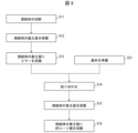
- FIG. 2 is a flow chart showing an example of a method for manufacturing the composite ceramics 1 according to this embodiment.
- the manufacturing method of the composite ceramics 1 according to this embodiment includes at least the following steps S1 to S4.
- a first raw material powder containing a garnet phosphor component 2, a nitride phosphor component 3, and a matrix component 4 is mixed (step S1 , mixing step).
- mixing the first raw material powder means mixing each component contained in the first raw material powder.
- the first raw material powder may contain the sintering aid.
- Dry mixing is used to mix the first raw material powder.
- any mixer may be used as long as powder mixing by a dry method is possible.
- step S2 first raw material powder accommodating step.
- step S3 the first raw material powder accommodated in the mold is sintered (step S3, sintering step).
- SPS discharge plasma sintering
- hot press method is used for sintering the first raw material powder.
- the SPS method and the hot press method are types of solid compression sintering methods, in which the first raw material powder accommodated in the mold is press-molded while being heated.
- the molded body is sintered by pulse electric heating while press-molding with mechanical pressure.
- electromagnetic energy due to pulse current, self-heating of the molded body, discharge plasma energy generated between each component, etc. are combined for sintering.
- the compact can be sintered.
- the SPS method it is possible to sinter by heating to a high temperature in a short period of time while applying mechanical pressure. can be sintered into a sintered body in which each component contained in is bonded at high density and substantially uniformly. In addition, since the SPS method requires a short sintering time, grain growth of each component can be suppressed.
- the hot press method sintering is performed in a pressurized atmosphere as in the SPS method.
- the sintering time is longer than that of the SPS method.
- the hot press method is excellent in mass productivity.
- the sintering temperature in the sintering step is preferably 1000°C or higher and 2000°C or lower. By setting the sintering temperature to 2000° C. or less, the sintering temperature is not too high, and it is possible to suppress the formation of oxides and the solid solution of the above components to form new compounds. Without losing the characteristics of each component.
- the sintering temperature is not too low, and the primary particles of the above components are likely to be in a bonded state.
- the components described above are mixed without solid solution, and a structure in which adjacent phases adhere to each other is likely to be formed. For this reason, for example, it becomes easy to obtain the composite ceramics 1 that has a sufficient processing strength as a bulk body and that outputs a suitable incandescent fluorescent light.
- the sintering time in the sintering step is not particularly limited, and may be any time from 5 minutes to 20 hours, for example.
- step S4 mold release step
- the method for manufacturing the composite ceramics 1 may further include an annealing step (step S5) for annealing the sintered body obtained in the sintering step after the releasing step.
- the annealing temperature is preferably 800°C or higher and 1500°C or lower, for example.
- the annealing time is not particularly limited, and may be any time from 5 minutes to 20 hours, for example.
- Annealing is preferably performed in a reducing atmosphere such as an N2 atmosphere or an H2 and N2 atmosphere.
- the method for manufacturing the composite ceramics 1 may further include a cutting/polishing step (step S6) in which at least one of cutting and polishing is applied to the sintered body.
- the size of the composite ceramics 1 is not particularly limited, and the sintered body taken out from the mold in the mold release process can be used as the composite ceramics 1 as it is. However, in order to make the composite ceramics 1 of a predetermined size, the obtained sintered body may be subjected to at least one of cutting and polishing as described above.
- the method of cutting the sintered body is not particularly limited, and for example, the sintered body may be sliced (cut) with a wire saw or the like.
- a thin composite ceramic 1 can be obtained by cutting the sintered body.
- the thin composite ceramics 1 may be manufactured without cutting by using a thin mold or by adjusting the amount of the first raw material powder contained in the mold.
- the method for polishing the sintered body is not particularly limited.
- the surface of the sintered body may be polished by rotating the polishing unit while discharging the polishing liquid from the discharge unit of the polishing apparatus.
- the thickness of the sintered body can be reduced while the surface can be made smooth. Therefore, the composite ceramic 1 having a thin thickness and a smooth surface can be obtained by performing polishing.
- the present embodiment is not limited to this. Only one of the annealing process and the cutting/polishing process may be performed. Also, the annealing step may be performed after the cutting/polishing step.
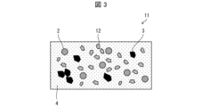
- FIG. 3 is a cross-sectional view showing an example of the structure of the composite ceramics 11 according to this embodiment.
- the composite ceramic 11 according to this embodiment has the same configuration as the composite ceramic 1 according to Embodiment 1, except that it further contains a light scattering component 12.
- the light scattering component 12 may be a light scatterer having a refractive index higher than that of the matrix component 4 by 0.21 or more.
- the composite ceramic further contains the light scattering component 12 in addition to the garnet phosphor component 2, the nitride phosphor component 3, and the matrix component 4, the sum of the matrix component 4 and the light scattering component 12 is
- the content is desirably 31 wt % or more and 95 wt % or less of the total components.
- the composite ceramics 11 which is excellent in light scattering properties and capable of efficiently extracting the generated fluorescence and excitation light to the outside.
- the light scattering component 12 includes, for example, at least one selected from the group consisting of AlN, cBN, SiC, AlN--SiC solid solution, and diamond. These light-scattering components are particularly excellent in light-scattering properties and can be suitably used as the light-scattering component 12 .
- the upper limit of the refractive index difference between the light scattering component 12 used in this embodiment and the matrix component 4 is not particularly limited. However, among MgO and Al 2 O 3 used for the matrix component 4, the refractive index of Al 2 O 3 having a low refractive index is 1.63. , the refractive index of SiC, which has the highest refractive index, is about 2.72. Therefore, when the above-exemplified light scattering component is used as the light scattering component 12, the maximum difference in refractive index between the light scattering component 12 and the matrix component 4 is 1.1.
- the number average particle diameter of the light scattering component 12 contained per unit volume of the composite ceramic 1 is preferably 0.25 ⁇ m or more and 40 ⁇ m or less, more preferably 0.5 ⁇ m or more and 20 ⁇ m or less.
- the number average particle size of the light scattering component 12 may be a value measured by SEM, or may be a specification described in a statement of delivery or a catalog. When the number average particle size of the light scattering component 12 is within the above range, light scattering is maximized by Mie scattering.
- the maximum light scattering effect can be obtained.
- the first raw material powder contains the raw material powder serving as the raw material of the light scattering component 12, so that the composite ceramics 11 can emit light. It contains a scattered component 12 . Therefore, the composite ceramics 11 can be manufactured by mixing the first raw material powder, which further contains the raw material powder of the light scattering component 12, in the mixing step (step S1).
- the composite ceramics 11 may also contain the sintering aid.
- FIG. 4 is a cross-sectional view showing an example of the structure of the composite ceramics 21 according to this embodiment.
- the composite ceramics 21 according to this embodiment has a laminated structure including a first ceramics layer 22 and a second ceramics layer 23 .
- the first ceramics layer 22 shown in FIG. 4 has the same configuration as the composite ceramics 1 according to the first embodiment.
- the second ceramic layer 23 is made of at least one selected from the group consisting of MgO and Al 2 O 3 and is bonded to one main surface of the first ceramic layer 22 .
- the second ceramic layer 23 having the above-described configuration is bonded onto the first ceramic layer 22, burning of the surface of the composite ceramic is suppressed even when strongly excited by laser light. can do. Therefore, according to the present embodiment, it is possible to provide the composite ceramic 12 capable of suppressing deterioration of the surface due to such scorching.
- the thickness of the first ceramics layer 22 is not particularly limited, and can be set to the same thickness as the composite ceramics 1 according to the first embodiment, for example.
- the thickness of the second ceramics layer 23 is not particularly limited, the second ceramics layer 23 does not contain a fluorescent component and does not contribute to fluorescence emission. It is desirable to be formed thinner than one ceramic layer 22 .
- the thickness of the second ceramics layer 23 is, for example, 30 ⁇ m or less.
- the thickness of the second ceramics layer 23 is desirably 1 ⁇ m or more, for example.
- the method of manufacturing the composite ceramics 21 is the same as the method of manufacturing the composite ceramics 1 according to the first embodiment, except for the following points.
- the method for manufacturing the composite ceramics 21 includes a step of accommodating a second raw material powder containing at least one selected from the group consisting of MgO and Al 2 O 3 and containing a second raw material powder less than the first raw material powder in a molding die. Including more.
- the first raw material powder and the second raw material powder accommodated in the molding die are sintered.
- a sintered body is formed in which the sintered body of the first raw material powder and the sintered body of the second raw material powder, which is thinner than the first raw material powder, are joined together.
- the composite ceramics 21 can be manufactured.
- the second raw powder containing step may be performed after the first raw powder containing step (step S2) (that is, between steps S2 and S3), and the first raw powder containing step ( It may be performed before step S2) (that is, between steps S1 and S2).
- the second raw powder containing step be performed twice before and after the first raw powder containing step.
- the step of accommodating the second raw material powder is performed twice before and after the step of accommodating the first raw material powder
- the second ceramic layer 23 is formed with the first ceramic layer 22 interposed therebetween after the mold release step (step S4).
- the second ceramic layer 23 on one main surface of the first ceramic layer 22 may be removed by grinding, polishing, or the like. Said removal may be performed in said cutting/polishing step.
- the sintered body is sliced (cut) so that one main surface of the first ceramic layer 22 has a second ceramic layer 23 on one main surface.
- a plurality of composite ceramics 21 having ceramic layers 23 formed thereon may be manufactured.
- the annealing process (step S5) may be performed as necessary.
- the composite ceramics 21 may also contain the sintering aid.
- the case where the first ceramic layer 22 has the same configuration as the composite ceramic 1 according to Embodiment 1 is illustrated as an example, but this embodiment is limited to this. not a thing
- the first ceramics layer 22 may have the same configuration as the composite ceramics 11 according to the second embodiment.
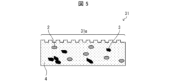
- FIG. 5 is a cross-sectional view showing an example of the structure of the composite ceramics 31 according to this embodiment.
- the composite ceramic 31 according to the present embodiment has, for example, the same configuration as the composite ceramic 1 according to the first embodiment, except that unevenness 31a is formed on one main surface. are doing.
- the method for manufacturing the composite ceramics 21 is the same as the method for manufacturing the composite ceramics 1 according to Embodiment 1, except that it further includes an unevenness forming step of forming unevennesses 31a on one main surface of the sintered body. is.
- the unevenness 31a is a dicer groove.
- this embodiment is not limited to this.
- the unevenness 31a may be formed by a dicer or laser processing, or the unevenness 31a may be formed by roughening the main surface by polishing.
- the composite ceramics 31 having the irregularities 31a formed on one main surface can scatter and efficiently extract the fluorescence and excitation light generated inside. be able to.
- the height of the unevenness 31a on the surface is not particularly limited as long as it can scatter the fluorescence and excitation light generated inside as described above.
- FIG. 5 shows an example in which the composite ceramics 31 has a structure in which unevenness 31 a is formed on one main surface of the composite ceramics 1 .
- the composite ceramics 31 according to this embodiment may have a structure in which one main surface of the composite ceramics 11 is formed with irregularities 31a.
- the composite ceramics 31 according to the present embodiment has a structure in which irregularities 31a are formed on the main surface of the second ceramics layer 23 of the composite ceramics 21 opposite to the first ceramics layer 22. good too.
- FIG. 6 shows a composite ceramic 1 provided with an AR (anti-reflection) coating film 41 on one main surface according to this embodiment.
- the AR coating film 41 is provided on the main surface of the composite ceramics 1, so that when the composite ceramics 1 is used as a phosphor element for laser illumination, excitation light is emitted on the irradiation surface of the excitation light. Light can be prevented from being reflected. Thereby, the loss of light when the excitation light is absorbed by the composite ceramics 1 can be reduced. Furthermore, fluorescence and scattered light generated in the phosphor of the composite ceramics 1 can be effectively extracted.
- a dielectric multilayer film such as SiO 2 , TiO 2 , Si 3 N 4 is used. These can be formed by a film forming method such as ion beam vapor deposition or sputtering.
- composite ceramics provided with the AR coating film 41 in this way may be referred to as composite ceramics with an AR coating film.
- Composite ceramics with an AR coating film that has been AR-coated in this manner is suitably used, for example, as a phosphor element for laser illumination.
- FIG. 7 is a cross-sectional view showing an example of the phosphor element 50 according to this embodiment.
- the phosphor element 50 shown in FIG. 7 includes the composite ceramics 1 provided with the AR coating film 41, the substrate 51, the adhesive layer 52, and the mirror 53 shown in FIG.
- the base material 51 is a supporting member that supports the composite ceramics 1 .
- Composite ceramics 1 is fixed on substrate 51 .
- the base material 51 is not particularly limited as long as the composite ceramics 1 can be fixed.
- the base material 51 includes metals such as SUS, Al, Cu, Mo, Ag, W, and the like. When the base material 51 is made of these metals, it can suitably reflect excitation light emitted from an excitation light source such as a laser light source.
- the phosphor element 50 having excellent thermal conductivity can be obtained.
- substrate 51 is not limited to such a non-transmissive substrate.
- substrate 51 may be a transmissive substrate such as, for example, monocrystalline sapphire or polycrystalline alumina, denoted Al 2 O 3 .
- the composite ceramic 1 is fixed to the base material 51 so that the AR coat film 41 is positioned on the main surface opposite to the base material 51, as shown in FIG.
- the mirror 53 is a reflector (mirror body) that reflects the light transmitted through the composite ceramics 1 .
- the mirror 53 is provided on the main surface of the composite ceramics 1 on the substrate 51 side.
- the main surface of the composite ceramic 1 on the substrate 51 side may be referred to as the "back main surface”
- the main surface on the opposite side of the substrate 51 may be referred to as the "front main surface”.
- the mirror 53 is provided on the back main surface side of the composite ceramics 1, and the AR coat film 41 is provided on the front main surface side of the composite ceramics.
- the mirror 53 is provided on the back main surface side of the composite ceramics 1 in this way, when the excitation light is applied to the front main surface side of the composite ceramics 1, the light transmitted through the composite ceramics 1 is reflected by the mirror 53. can be reflected. Thereby, the utilization efficiency of light can be improved.
- the mirror 53 is not particularly limited as long as it can reflect the light transmitted through the composite ceramics 1.
- a silver-based mirror containing silver or a silver alloy, which is a specular reflection positive material, is preferably used.
- the adhesive layer 52 is a layer that bonds the composite ceramics 1 provided with the mirror 53 and the base material 51 .
- the adhesive material used for the adhesive layer 52 is not particularly limited as long as it can adhere the composite ceramics 1 provided with the mirror 53 and the base material 51 .
- Examples of the adhesive material include silver-based or silver-alloy based inorganic adhesives.
- FIG. 8 is a flow chart showing an example of a method for manufacturing the phosphor element 50 shown in FIG.
- a cutting step (step S11) of cutting the sintered body, and a back main surface of the sintered body A back main surface polishing step (step S12) is performed.
- the cutting/grinding step is not essential.
- step S13 a film of the mirror 53 is formed on the back main surface of the sintered body (step S13, mirror film forming step).
- step S13 mirror film forming step
- the substrate 51 is prepared (step S21, substrate preparation step).
- step S13 the base material 51 and the mirror-equipped composite ceramics obtained in step S13 are bonded together with an adhesive material forming the adhesive layer 52 (step S14, bonding step).
- step S15 front main surface polishing step
- step S16 AR coat film formation step
- the front main surface polishing process is performed after the bonding process, but the present embodiment is not limited to this.
- the front and main surface polishing step may be performed before the bonding step.
- the phosphor element 50 is not limited to the structure shown in FIG.
- the phosphor element 50 may include, for example, the composite ceramics 1 and a substrate 51 to which the composite ceramics 1 is fixed.
- the composite ceramics 1 instead of the composite ceramics 1, the composite ceramics 11, the composite ceramics 21, or the composite ceramics 31 may be provided. Composite ceramics obtained by combining them may also be used.
- composite ceramics can be suitably used for phosphor elements for laser illumination (in other words, phosphor elements for laser illumination devices).
- the laser illumination device includes a phosphor element, a laser light source that irradiates excitation light to the composite ceramics in the phosphor element, and a condensing member that collects the light output from the composite ceramics in the phosphor element ( (first condensing member).
- FIG. 9 is a cross-sectional view showing an example of a laser illumination device 60 according to this embodiment.
- a laser illumination device 60 shown in FIG. 9 includes, for example, a phosphor element 50 shown in FIG. 8 as an example of the phosphor element.
- a laser illumination device 60 shown in FIG. 9 includes a laser light source 61 as the laser light source and a lens 63 as the first condensing member.
- the laser illumination device 60 shown in FIG. 9 includes a lens 62 as a second condensing member for condensing the excitation light output from the laser light source 61 .
- the laser light source 61 irradiates the composite ceramics 1 in the phosphor element 50 with the excitation light L1 as the first light through the lens 62 .
- the excitation light L1 output from the laser light source 61 is condensed by the lens 62, and the lens 62
- the composite ceramics 1 in the phosphor element 50 is irradiated with the light from above.
- the composite ceramic 1 absorbs at least part of the excitation light L1' and outputs second light including light with a wavelength different from the excitation light L1' (that is, light with a wavelength different from the excitation light L1).
- the garnet phosphor component 2 described above emits, for example, yellow fluorescence Y by the blue light that is the excitation light L1
- the nitride phosphor component 3 emits red fluorescence by the blue light that is the excitation light L1. Emit R.
- these phosphors scatter the blue light that does not contribute to the excitation in the blue light that is the excitation light L1, and transmits it as blue scattered light B. As shown in FIG.
- the phosphor element 50 may include the composite ceramics according to the present disclosure and the substrate 51 as described in the fifth embodiment.
- the composite ceramic may be the composite ceramic described in any one of Embodiments 1 to 4, or may be a composite ceramic obtained by combining them.
- the laser light source 61 is not particularly limited as long as it can irradiate the excitation light L1.
- a blue semiconductor LD LD: laser diode
- irradiates blue light as the excitation light L1 as described above can be cited. be done.
- the phosphor element 50 When the phosphor element 50 includes the mirror 52 as described above, or when the base material 51 is a non-transmissive base material that does not transmit the excitation light L1, the phosphor element 50 is positioned on the side of the emitted light of the laser light source 61. It is arranged so that the composite ceramics 1 is positioned.
- the base material 51 is a transmissive base material and does not have a reflector such as the mirror 52 on the back main surface side of the composite ceramics 1, the side of the base material 51 opposite to the fixed surface of the composite ceramics 1
- the excitation light L1 is irradiated from the surface of .
- the second light is emitted from the front main surface side of the composite ceramics 1 .
- both the first light collecting member and the second light collecting member are lenses
- these condensing members may be lenses or mirrors.
- Example 1 As shown in FIG. 10, in Example 1, the contents of YAG as a garnet-based phosphor component, Sr 2 Si 5 N 8 as a nitride-based phosphor component, and Al 2 O 3 as a matrix component were However, each raw material powder was mixed so as to be 25 wt %, 25 wt %, and 50 wt %, respectively.
- this raw material powder was filled into a mold and sintered at 1350°C for 3 minutes in a nitrogen atmosphere using the SPS method to produce composite ceramics.
- the laser power dependence of the fluorescence power of the resulting composite ceramics was measured using a phosphor evaluation device equipped with a laser light source, an integrating sphere, and a spectroscope.
- the excitation laser beam in the laser light source had a diameter of 1 mm, an excitation laser wavelength of 450 nm, and a continuous excitation laser beam. The results are shown in FIG.
- the obtained composite ceramics was irradiated with excitation light from a laser light source, and the fluorescence spectrum of the beam output from the composite ceramics through a lens was measured using a fluorescence spectroscope. More specifically, using a spectroscope manufactured by Ocean Photonics Co., Ltd., the emission spectrum was measured under room temperature conditions with the excitation wavelength fixed at 441 nm. The results are shown in FIG.
- Example 2 As shown in FIG . 10, in Example 2, each raw material powder was mixed so that the contents of YAG, Sr2Si5N8 , and Al2O3 were 15 wt%, 15 wt%, and 70 wt%, respectively. Mixed. Except for this point, in Example 2, the same operation as in Example 1 was performed to produce a composite ceramic.
- Example 2 the same phosphor evaluation device as in Example 1 was used to measure the laser power dependence of the fluorescence power of the obtained composite ceramics. The results are shown in FIG.
- Example 2 Using the same device as in Example 1, the fluorescence spectrum of the beam output from the composite ceramics through the lens was measured using the same fluorescence spectrometer as in Example 1. The results are shown in FIG.
- Example 3 As shown in FIG. 10, in Example 3, each raw material powder was mixed so that the contents of YAG, Sr2Si5N8 , and Al2O3 were 5 wt%, 5 wt%, and 90 wt % , respectively. Mixed and sintered at 1300°C. Except for this point, in Example 3, the same operation as in Example 1 was performed to produce a composite ceramic.
- Example 2 the same phosphor evaluation device as in Example 1 was used to measure the laser power dependence of the fluorescence power of the obtained composite ceramics. The results are shown in FIG.
- Example 2 the fluorescence spectrum of the beam output from the composite ceramics through the lens was measured using the same fluorescence spectrometer as in Example 1. The results are shown in FIG.
- Comparative Example 1 As shown in FIG. 10, in Comparative Example 1, only Sr 2 Si 5 N 8 was filled in the mold and sintered at 1800°C. Except for this point, in Comparative Example 1, the same operation as in Example 1 was performed to produce a composite ceramic for comparison.
- Example 2 the same phosphor evaluation device as in Example 1 was used to measure the laser power dependence of the fluorescence power of the obtained composite ceramics. This result is shown in FIG.
- Example 2 Using the same device as in Example 1, the fluorescence spectrum of the beam output from the composite ceramics through the lens was measured using the same fluorescence spectrometer as in Example 1. The results are shown in FIG.
- Example 4 As shown in FIG. 22, in Example 4 , MgO was used instead of Al2O3 , and the contents of YAG, Sr2Si5N8 , and MgO were 15 wt%, 15 wt% , and 70 wt%, respectively. %, and sintered at 1300°C. Except for this point, in Example 4, the same operation as in Example 1 was performed to produce a composite ceramic.
- Example 2 the same phosphor evaluation device as in Example 1 was used to measure the laser power dependence of the fluorescence power of the obtained composite ceramics. The results are shown in FIG.
- Example 2 Using the same device as in Example 1, the fluorescence spectrum of the beam output from the composite ceramics through the lens was measured using the same fluorescence spectrometer as in Example 1. The results are shown in FIG.
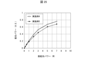
- Example 5 As shown in FIG. 22, in Example 5, about 10% of MgO was changed to AlN as a light scattering component, and the contents of YAG, Sr2Si5N8 , MgO, and AlN were each 15 wt. %, 15 wt %, 63 wt %, and 7 wt %. Except for this point, in Example 5, the same operation as in Example 1 was performed to produce a composite ceramic.
- Example 4 the same phosphor evaluation device as in Example 1 was used to measure the laser power dependence of the fluorescence power of the obtained composite ceramics. This result is shown in FIG. 23 together with the laser power dependence of the fluorescence power of the composite ceramics obtained in Example 4.
- the SEM image shown in FIG. 14 is a backscattered electron image, in which the portions composed of heavy elements appear white and the portions composed of light elements appear dark. Moreover, the shape of each component is a shape corresponding to the shape of the raw material particles. From the results shown in FIG . 14, the obtained composite ceramic contains YAG, Sr2Si5N8 , and Al2O3 , and Al2O3 surrounds YAG and Sr2Si5N8 . It was confirmed that it was sintered.
- the nitride-based phosphor component Sr 2 Si 5 N 8 is an oxide matrix component such as Al 2 O 3 I was able to confirm that there were still some left.
- the nitride phosphor has low excitation light power resistance (laser power resistance), and the garnet phosphor component and the matrix component are low. It can be seen that the pumping light power resistance is greatly improved by the addition.
- the fluorescent power was improved by about 10% or more by including, for example, AlN having a high refractive index as a light scattering component as part of the matrix component.
Abstract
A composite ceramic (1) comprises a sintered compact containing: a garnet-type phosphor component (2); a nitride-type phosphor component (3); and a matrix component (4) comprising at least one selected from the group consisting of MgO and Al2O3. The content ratio of the matrix component is 31 wt% to 95 wt% with respect to the total components. Sintering is conducted with the matrix component disposed in such a manner as to enclose the garnet-type phosphor component and the nitride-type phosphor component.
Description
本開示は、ガーネット系蛍光体成分と窒化物系蛍光体成分とマトリックス成分とを含むコンポジットセラミックス、およびそれを備えた、蛍光体素子およびレーザー照明装置、並びに、コンポジットセラミックスの製造方法に関する。
The present disclosure relates to composite ceramics containing a garnet-based phosphor component, a nitride-based phosphor component, and a matrix component, a phosphor element and a laser illumination device having the same, and a method for manufacturing the composite ceramics.
レーザー照明装置は、他の照明装置よりも省エネで、小型かつ高輝度であり、プロジェクタ用の照明装置、自動車のヘッドライト用の照明装置として、既に実用化が始まっている。また、家庭用照明市場でも、既存のLED(発光ダイオード)照明装置および蛍光灯からレーザー照明装置への置き換えが期待され、今後、レーザー照明の市場が急拡大すると予想されている。
Laser lighting devices are more energy efficient, compact, and brighter than other lighting devices, and have already begun to be put into practical use as lighting devices for projectors and automobile headlights. Also, in the home lighting market, replacement of existing LED (light emitting diode) lighting devices and fluorescent lamps with laser lighting devices is expected, and the laser lighting market is expected to expand rapidly in the future.
しかしながら、このようなレーザー照明装置用の蛍光体として実用化されつつあるコンポジットセラミックスは、蛍光体成分として、青色光を黄色に変換するYAG(イットリウム・アルミニウム・ガーネット)系蛍光体を使用したものである。例えば、特許文献1には、コンポジットセラミックスとして、Ceを含有するYAGからなる蛍光体相と、Al2O3とAlNの少なくとも一方からなるマトリックス相と、不純物とを所定の範囲の量だけ含むセラミックス複合体が開示されている。
However, composite ceramics, which are being put to practical use as phosphors for such laser lighting devices, use YAG (yttrium-aluminum-garnet)-based phosphors that convert blue light to yellow as phosphor components. be. For example, Patent Document 1 discloses, as composite ceramics, ceramics containing a phosphor phase made of YAG containing Ce, a matrix phase made of at least one of Al 2 O 3 and AlN, and impurities within a predetermined range. A composite is disclosed.
一方、近年、赤色系の蛍光を発光する赤色系蛍光体を含んだコンポジットセラミックスの開発も行われている。例えば、特許文献2には、コンポジットセラミックスとして、AlN粉末と蛍光体粉末との混合物を放電プラズマ焼結法により焼結し、AlN粉末を融解した後、冷却することで製造される蛍光物質成形体が開示されている。なお、ここで、赤色系蛍光体とは、赤色~オレンジ色の光を発する蛍光体を示す。そして、特許文献2には、上記蛍光体粉末に窒化物系蛍光体を用いてもよいことが開示されている。
On the other hand, in recent years, composite ceramics containing red phosphors that emit red fluorescence have also been developed. For example, in Patent Document 2, as a composite ceramic, a fluorescent substance molded body is produced by sintering a mixture of AlN powder and phosphor powder by a discharge plasma sintering method, melting the AlN powder, and then cooling it. is disclosed. Here, the red phosphor means a phosphor that emits red to orange light. Patent Document 2 discloses that a nitride-based phosphor may be used as the phosphor powder.
しかしながら、緻密なセラミックスを実現するためには原料を高温で焼結する必要があり、焼結時に高温にすると、特に窒化物系蛍光体が特性劣化し易い。そもそも、難焼結体である窒化物系蛍光体やAlNを用いたコンポジットセラミックスは、焼結自体が難しい。このため、赤色系蛍光体を含んだ、レーザー励起に耐え得る高パワー励起用のコンポジットセラミックスは実現されていない。
However, in order to realize dense ceramics, it is necessary to sinter the raw material at high temperature, and if the temperature is raised during sintering, the characteristics of nitride-based phosphors in particular are likely to deteriorate. In the first place, it is difficult to sinter composite ceramics using nitride-based phosphors and AlN, which are difficult to sinter. For this reason, composite ceramics for high-power excitation that contain a red phosphor and can withstand laser excitation have not been realized.
本開示の一態様は、上記問題点に鑑みなされたものであり、その目的は、比較的容易に製造することができる、レーザー照明用の赤色系蛍光体を含んだコンポジットセラミックス、およびそれを備えた、蛍光体素子およびレーザー照明装置、並びに、そのようなコンポジットセラミックスの製造方法を提供することにある。
One aspect of the present disclosure has been made in view of the above problems, and an object thereof is to provide a composite ceramic containing a red phosphor for laser illumination, which can be produced relatively easily, and a composite ceramic comprising the same. Another object of the present invention is to provide a phosphor element, a laser illumination device, and a method for manufacturing such composite ceramics.
上記の課題を解決するために、本開示の一態様に係るコンポジットセラミックスは、ガーネット系蛍光体成分と、窒化物系蛍光体成分と、マトリックス成分とを含む焼結体からなるコンポジットセラミックスであって、上記マトリックス成分は、MgOおよびAl2O3からなる群より選ばれる少なくとも一種であり、上記マトリックス成分の含有率が、全成分の31wt%以上、95wt%以下の範囲内であり、上記マトリックス成分は、上記ガーネット系蛍光体成分と上記窒化物系蛍光体成分とを取り囲んで焼結されている。
In order to solve the above problems, a composite ceramic according to one aspect of the present disclosure is a composite ceramic made of a sintered body containing a garnet phosphor component, a nitride phosphor component, and a matrix component, , the matrix component is at least one selected from the group consisting of MgO and Al 2 O 3 , the content of the matrix component is in the range of 31 wt% or more and 95 wt% or less of the total components, and the matrix component surrounds the garnet-based phosphor component and the nitride-based phosphor component and is sintered.
上記の課題を解決するために、本開示の一態様に係る蛍光体素子は、本開示の一態様に係るコンポジットセラミックスと、上記コンポジットセラミックスを固定する基材とを備えている。
In order to solve the above problems, a phosphor element according to one aspect of the present disclosure includes composite ceramics according to one aspect of the present disclosure, and a base material for fixing the composite ceramics.
上記の課題を解決するために、本開示の一態様に係るレーザー照明装置は、本開示の一態様に係る蛍光体素子と、上記蛍光体素子における上記コンポジットセラミックスに励起光を照射するレーザー光源と、上記蛍光体素子における上記コンポジットセラミックスから出力された光を集光する集光部材とを備えている。
In order to solve the above problems, a laser illumination device according to one aspect of the present disclosure includes a phosphor element according to one aspect of the present disclosure, and a laser light source that irradiates the composite ceramics in the phosphor element with excitation light. and a condensing member condensing light output from the composite ceramics in the phosphor element.
上記の課題を解決するために、本開示の一態様に係るコンポジットセラミックスの製造方法は、ガーネット系蛍光体成分と、窒化物系蛍光体成分と、マトリックス成分とを含む第1原料粉を混合する混合工程と、混合した上記第1原料粉を成形型に収容する第1原料粉収容工程と、上記成形型に収容した上記第1原料粉を、放電プラズマ焼結法またはホットプレス法で焼結する焼結工程と、上記焼結工程で得られた焼結体を上記成形型から取り出す離型工程とを含む。
In order to solve the above problems, a method for manufacturing a composite ceramic according to an aspect of the present disclosure mixes a first raw material powder containing a garnet-based phosphor component, a nitride-based phosphor component, and a matrix component. A mixing step, a first raw material powder accommodating step of accommodating the mixed first raw material powder in a molding die, and sintering the first raw material powder accommodated in the molding die by a discharge plasma sintering method or a hot press method. and a releasing step of removing the sintered body obtained in the sintering step from the mold.
本開示の一態様によれば、比較的容易に製造することができる、レーザー照明用の赤色系蛍光体を含んだコンポジットセラミックス、およびそれを備えた、蛍光体素子およびレーザー照明装置、並びに、そのようなコンポジットセラミックスの製造方法を提供することができる。
According to one aspect of the present disclosure, a composite ceramic containing a red phosphor for laser illumination, which can be produced relatively easily, a phosphor element and a laser illumination device including the same, and the It is possible to provide a method for producing such composite ceramics.
本開示の実施形態について、以下に説明する。なお、説明の便宜上、先に説明した部材と同じ機能を有する部材については、同じ符号を付記し、その説明を繰り返さない。また、実施形態2以降の実施形態では、先に説明した実施形態との相異点について説明する。特に説明がない場合でも、実施形態2以降の実施形態において、先に説明した実施形態と同様の変形が可能であることは、言うまでもない。また、以下、2つの数AおよびBについての「A~B」という記載は、特に明示されない限り、「A以上かつB以下」を意味する。
An embodiment of the present disclosure will be described below. For convenience of explanation, members having the same functions as those of the previously explained members are denoted by the same reference numerals, and the explanation thereof will not be repeated. Also, in the second and subsequent embodiments, differences from the previously described embodiments will be described. Even if there is no particular description, it goes without saying that modifications similar to those of the previously described embodiments are possible in the second and subsequent embodiments. Further, hereinafter, the description "A to B" for two numbers A and B means "A or more and B or less" unless otherwise specified.
〔実施形態1〕
図1は、本実施形態に係るコンポジットセラミックス1の組織の一例を示す断面図である。 [Embodiment 1]
FIG. 1 is a cross-sectional view showing an example of the structure of a composite ceramic 1 according to this embodiment.
図1は、本実施形態に係るコンポジットセラミックス1の組織の一例を示す断面図である。 [Embodiment 1]
FIG. 1 is a cross-sectional view showing an example of the structure of a composite ceramic 1 according to this embodiment.
本実施形態に係るコンポジットセラミックス1は、2種類以上の発光波長を有する蛍光体成分と、マトリックス成分とを含む焼結体からなる多波長発光のセラミックス複合体である。
The composite ceramic 1 according to this embodiment is a multi-wavelength luminescent ceramic composite made of a sintered body containing phosphor components having two or more emission wavelengths and a matrix component.
図1に示すコンポジットセラミックス1は、ガーネット系蛍光体成分2と、窒化物系蛍光体成分3と、マトリックス成分4とを含み、マトリックス成分4が、ガーネット系蛍光体成分2と窒化物系蛍光体成分3とを取り囲んで焼結された構造を有している。
The composite ceramic 1 shown in FIG. 1 includes a garnet-based phosphor component 2, a nitride-based phosphor component 3, and a matrix component 4, and the matrix component 4 includes the garnet-based phosphor component 2 and the nitride-based phosphor. It has a sintered structure surrounding component 3.
このため、コンポジットセラミックス1は、図1に示すように、マトリックス成分4中にガーネット系蛍光体成分2および窒化物系蛍光体成分3が島状に混在した海島構造を有している。つまり、コンポジットセラミックス1は、比較的連続に見える海状のマトリックス成分4中に、ガーネット系蛍光体成分2および窒化物系蛍光体成分3が島状に分散された構造を有している。ガーネット系蛍光体成分2と窒化物系蛍光体成分3との間には、マトリックス成分4が充填されている。
Therefore, as shown in FIG. 1, the composite ceramic 1 has a sea-island structure in which the garnet-based phosphor component 2 and the nitride-based phosphor component 3 are mixed in islands in the matrix component 4 . That is, the composite ceramic 1 has a structure in which the garnet-based phosphor component 2 and the nitride-based phosphor component 3 are dispersed like islands in a relatively continuous sea-like matrix component 4 . A matrix component 4 is filled between the garnet phosphor component 2 and the nitride phosphor component 3 .
ガーネット系蛍光体成分2と、窒化物系蛍光体成分3と、マトリックス成分4とは、互いに固着されている。
The garnet-based phosphor component 2, the nitride-based phosphor component 3, and the matrix component 4 are adhered to each other.
コンポジットセラミックス1は、ガーネット系蛍光体成分2からなる第1の蛍光体相と、窒化物系蛍光体成分3からなる第2の蛍光体相と、マトリックス成分4からなるマトリックス相と、の少なくとも3相を有している。
The composite ceramic 1 comprises at least three phases of a first phosphor phase comprising a garnet phosphor component 2, a second phosphor phase comprising a nitride phosphor component 3, and a matrix phase comprising a matrix component 4. have phases.
このため、コンポジットセラミックス1は、少なくとも上記3相が混在し、互いに隣接する相が固着した構造を有している。ここで、少なくとも上記3相が混在し、互いに隣接する相が固着した構造とは、上記3相が固溶せずに、固体中でそれぞれの相の領域に分離して、互いに隣接する相が固着している構造を示す。また、焼結助剤や不純物が粒界に存在する場合も含む。あるいは、粒子間でわずかに変質相や融解相があっても、基本的に3相の構造をしっかり有している場合はコンポジットセラミックスとする。
For this reason, the composite ceramic 1 has a structure in which at least the above three phases are mixed and phases adjacent to each other are fixed. Here, the structure in which at least the above three phases are mixed and the phases adjacent to each other are fixed means that the above three phases are not solid-dissolved, but are separated into regions of each phase in the solid, and the phases adjacent to each other are separated. A sticking structure is shown. It also includes the case where sintering aids and impurities are present at grain boundaries. Alternatively, even if there are slight alteration phases or melting phases between particles, if they basically have a solid three-phase structure, they are considered composite ceramics.
なお、3相以上の相のうち、少なくとも互いに隣接する相が互いに固溶した固溶体は、コンポジットセラミックス1から除かれる。また、3相以上の相が単に直接接合された接合物、並びに、無機ガラスおよび有機バインダーの少なくとも一方によって少なくとも上記3相が固められた組成物は、コンポジットセラミックス1から除かれる。
A solid solution in which at least the phases adjacent to each other among the three or more phases form a solid solution with each other is excluded from the composite ceramics 1 . Composite ceramics 1 excludes joints in which three or more phases are simply directly joined, and compositions in which at least the three phases are solidified by at least one of inorganic glass and organic binder.
(ガーネット系蛍光体成分2)
本開示において、ガーネット系蛍光体成分2とは、結晶構造がガーネット構造を有する蛍光体を示す。ガーネット系蛍光体成分2は、屈折率が大きく、蛍光特性に優れた蛍光体であり、例えば、青色励起光によって、黄色~緑色の黄色系の蛍光を発光する。また、励起光のうち励起に寄与しなかった光は、散乱させて透過する。このため、ガーネット系蛍光体成分2は、青色散乱光と、黄色系の蛍光とを出力する。 (Garnet phosphor component 2)
In the present disclosure, the garnet-basedphosphor component 2 indicates a phosphor having a garnet crystal structure. The garnet-based phosphor component 2 is a phosphor having a large refractive index and excellent fluorescence characteristics, and emits yellowish to greenish yellowish fluorescence, for example, by blue excitation light. In addition, the light that does not contribute to the excitation among the excitation light is scattered and transmitted. Therefore, the garnet-based phosphor component 2 outputs blue scattered light and yellowish fluorescence.
本開示において、ガーネット系蛍光体成分2とは、結晶構造がガーネット構造を有する蛍光体を示す。ガーネット系蛍光体成分2は、屈折率が大きく、蛍光特性に優れた蛍光体であり、例えば、青色励起光によって、黄色~緑色の黄色系の蛍光を発光する。また、励起光のうち励起に寄与しなかった光は、散乱させて透過する。このため、ガーネット系蛍光体成分2は、青色散乱光と、黄色系の蛍光とを出力する。 (Garnet phosphor component 2)
In the present disclosure, the garnet-based
ガーネット系蛍光体成分2は、耐熱性に優れ、例えばハイパワーの励起光LD(レーザーダイオード)を照射した場合でも、劣化を抑えることができる。
The garnet-based phosphor component 2 has excellent heat resistance, and can suppress deterioration even when irradiated with, for example, a high-power excitation light LD (laser diode).
ガーネット系蛍光体成分2としては、例えば、YAG(イットリウム・アルミニウム・ガーネット)系蛍光体が挙げられる。なお、YAG系蛍光体とは、YAG蛍光体の結晶構造に帰属できる蛍光体を示す。
As the garnet-based phosphor component 2, for example, a YAG (yttrium-aluminum-garnet)-based phosphor can be used. The YAG-based phosphor indicates a phosphor that can be attributed to the crystal structure of the YAG phosphor.
YAG系蛍光体としては、例えば、(Ce,Y)3Al5O12、(Ce,Lu)3Al5O12、(Ce,Lu,Y)3Al5O12、(Ce,Lu,Y)3(Al,Ga)5O12からなる群より選ばれる少なくとも一種が挙げられる。コンポジットセラミックス1がガーネット系蛍光体成分2として上記YAG系蛍光体を含むことで、黄色~緑色の黄色系の蛍光を出力するコンポジットセラミックス1を容易に実現することができる。また、コンポジットセラミックス1がガーネット系蛍光体成分2として上記YAG系蛍光体を含むことで、より蛍光特性に優れたコンポジットセラミックス1を得ることができる。
Examples of YAG phosphors include (Ce, Y) 3 Al 5 O 12 , (Ce, Lu) 3 Al 5 O 12 , (Ce, Lu, Y) 3 Al 5 O 12 , (Ce, Lu, Y ) 3 (Al, Ga) 5 O 12 . By including the YAG phosphor as the garnet phosphor component 2 in the composite ceramic 1, it is possible to easily realize the composite ceramic 1 that outputs yellowish to greenish yellow fluorescence. In addition, since the composite ceramics 1 contains the YAG-based phosphor as the garnet-based phosphor component 2, the composite ceramics 1 having more excellent fluorescence characteristics can be obtained.
(窒化物系蛍光体成分3)
本開示において、窒化物系蛍光体成分3とは、窒素を含む蛍光体を示す。窒化物系蛍光体成分3としては、具体的には、窒化物蛍光体および酸窒化物蛍光体からなる群より選ばれる少なくとも一種の蛍光体が挙げられる。 (Nitride phosphor component 3)
In the present disclosure, the nitride-basedphosphor component 3 indicates a phosphor containing nitrogen. Specific examples of the nitride phosphor component 3 include at least one phosphor selected from the group consisting of nitride phosphors and oxynitride phosphors.
本開示において、窒化物系蛍光体成分3とは、窒素を含む蛍光体を示す。窒化物系蛍光体成分3としては、具体的には、窒化物蛍光体および酸窒化物蛍光体からなる群より選ばれる少なくとも一種の蛍光体が挙げられる。 (Nitride phosphor component 3)
In the present disclosure, the nitride-based
窒化物系蛍光体成分3は、蛍光特性に優れた、赤色~オレンジ色の赤色系の蛍光を発する赤色系蛍光体であり、例えば、青色励起光によって赤色系の蛍光を発光する。また、励起光のうち励起に寄与しなかった光は、散乱させて透過する。このため、窒化物系蛍光体成分3は、青色散乱光および赤色系蛍光を出力する。コンポジットセラミックス1が窒化物系蛍光体成分3を含むことで、電球色の蛍光を出力する3元系のコンポジットセラミックスを得ることができる。また、コンポジットセラミックス1が窒化物系蛍光体成分3を含むことで、より蛍光特性に優れたコンポジットセラミックス1を得ることができる。
The nitride-based phosphor component 3 is a red-based phosphor that emits red-to-orange red-based fluorescence with excellent fluorescence properties. For example, it emits red-based fluorescence with blue excitation light. In addition, the light that does not contribute to the excitation among the excitation light is scattered and transmitted. Therefore, the nitride phosphor component 3 outputs blue scattered light and red fluorescence. By including the nitride-based phosphor component 3 in the composite ceramic 1, it is possible to obtain a ternary composite ceramic that outputs incandescent fluorescent light. In addition, since the composite ceramic 1 contains the nitride-based phosphor component 3, the composite ceramic 1 having more excellent fluorescence characteristics can be obtained.
窒化物系蛍光体成分3としては、例えば、それぞれEuおよびCeのうち少なくとも一方の元素で賦活された、Sr2Si5N8、(Sr,Ba)2Si5N8、(Ca,Sr,Ba)2Si5N8からなる群より選ばれる少なくとも一種の窒化物蛍光体が挙げられる。以下、説明の便宜上、これら窒化物蛍光体を、窒化物蛍光体(A)と称する場合がある。EuおよびCeは賦活剤であり、結晶中にドープされている。このように、窒化物系蛍光体成分3としては、例えば、Eu:Sr2Si5N8、Eu:(Sr,Ba)2Si5N8、Eu:(Ca,Sr,Ba)2Si5N8、Ce:Sr2Si5N8、Ce:(Sr,Ba)2Si5N8、Ce:(Ca,Sr,Ba)Si5N8、(Eu,Ce):Sr2Si5N8、(Eu,Ce):(Sr,Ba)2Si5N8、(Eu,Ce):(Ca,Sr,Ba)2Si5N8等の窒化物蛍光体(A)が挙げられる。
Examples of the nitride-based phosphor component 3 include Sr 2 Si 5 N 8 , (Sr, Ba) 2 Si 5 N 8 , (Ca, Sr, Ba) at least one nitride phosphor selected from the group consisting of 2Si5N8 . Hereinafter, for convenience of explanation, these nitride phosphors may be referred to as nitride phosphor (A). Eu and Ce are activators and are doped in the crystal. Thus, as the nitride- based phosphor component 3, for example, Eu:Sr2Si5N8, Eu:(Sr,Ba)2Si5N8 , Eu : ( Ca , Sr , Ba) 2Si5 N 8 , Ce: Sr 2 Si 5 N 8 , Ce: (Sr, Ba) 2 Si 5 N 8 , Ce: (Ca, Sr, Ba) Si 5 N 8 , (Eu, Ce): Sr 2 Si 5 N 8 , (Eu, Ce): (Sr, Ba) 2 Si 5 N 8 , (Eu, Ce): (Ca, Sr, Ba) 2 Si 5 N 8 and other nitride phosphors (A).
コンポジットセラミックス1が窒化物系蛍光体成分3としてこのようなアルカリ土類窒化ケイ素を含むことで、安定した赤色系の蛍光を発するコンポジットセラミックス1を作製することができる。
By including such an alkaline earth silicon nitride as the nitride-based phosphor component 3 in the composite ceramic 1, the composite ceramic 1 that emits stable reddish fluorescence can be produced.
なお、これら窒化物蛍光体(A)は、上記組成式におけるSiの一部およびNの一部のうち少なくとも一方が置換されていてもよい。Siの一部が置換される場合、SiはAlに置換される。Nの一部が置換される場合、NはOに置換される。
In these nitride phosphors (A), at least one of part of Si and part of N in the above composition formula may be substituted. When part of Si is substituted, Si is substituted with Al. N is replaced with O when part of N is replaced.
したがって、窒化物系蛍光体成分3は、Sr2Si5N8、(Sr,Ba)2Si5N8、あるいは(Ca,Sr,Ba)2Si5N8において、Siの一部がAlに置換された窒化物蛍光体であってもよく、Nの一部がOに置換された酸窒化物蛍光体であってもよい。また、Siの一部がAlに置換され、Nの一部がOに置換された酸窒化物蛍光体であってもよい。一例として、例えば、EuおよびCeのうち少なくとも一方の元素で賦活された、(Sr,Ba)2(Si,Al)5N8、(Sr,Ba)2(Si,Al)5(N,O)8等が挙げられる。
Therefore, the nitride-based phosphor component 3 is Sr 2 Si 5 N 8 , (Sr, Ba) 2 Si 5 N 8 , or (Ca, Sr, Ba) 2 Si 5 N 8 , in which part of Si is Al It may be a nitride phosphor in which N is substituted with or an oxynitride phosphor in which a part of N is replaced with O. Further, an oxynitride phosphor in which part of Si is replaced with Al and part of N is replaced with O may be used. As an example, for example, (Sr, Ba) 2 (Si, Al) 5 N 8 , (Sr, Ba) 2 (Si, Al) 5 (N, O ) 8 and the like.
コンポジットセラミックス1が窒化物系蛍光体成分3としてこのような窒化物蛍光体および酸窒化物蛍光体の少なくとも一方を含むことで、より信頼性の高いコンポジットセラミックス1を実現することができる。
By including at least one of such a nitride phosphor and an oxynitride phosphor as the nitride-based phosphor component 3 in the composite ceramic 1, a more reliable composite ceramic 1 can be realized.
また、窒化物系蛍光体成分3は、例えば、それぞれEuおよびCeのうち少なくとも一方の元素で賦活された、CaAlSiN3および(Ca,Sr)AlSiN3からなる群より選ばれる少なくとも一種の窒化物蛍光体であってもよい。以下、説明の便宜上、これら窒化物蛍光体を、窒化物蛍光体(B)と称する場合がある。EuおよびCeは賦活剤であり、結晶中にドープされている。このように、窒化物系蛍光体成分3としては、例えば、Eu:CaAlSiN3、Eu:(Ca,Sr)AlSiN3、Ce:CaAlSiN3、Ce:(Ca,Sr)AlSiN3、(Eu,Ce):CaAlSiN3、(Eu,Ce):(Ca,Sr)AlSiN3等の窒化物蛍光体(B)であってもよい。
Further, the nitride-based phosphor component 3 is, for example, at least one nitride phosphor selected from the group consisting of CaAlSiN 3 and (Ca, Sr)AlSiN 3 activated with at least one element of Eu and Ce, respectively. It can be a body. Hereinafter, for convenience of explanation, these nitride phosphors may be referred to as nitride phosphor (B). Eu and Ce are activators and are doped in the crystal. Thus, the nitride-based phosphor component 3 includes, for example, Eu:CaAlSiN 3 , Eu:(Ca,Sr)AlSiN 3 , Ce:CaAlSiN 3 , Ce:(Ca,Sr)AlSiN 3 , (Eu, Ce ): CaAlSiN 3 , (Eu, Ce): (Ca, Sr) AlSiN 3 and other nitride phosphors (B).
さらに、上記窒化物系蛍光体成分3としては、窒化物蛍光体(A)および窒化物蛍光体(B)以外に、例えば、Ceで賦活された(La、Y)3Si6N11等であってもよい。
Further, as the nitride-based phosphor component 3, in addition to the nitride phosphor (A) and the nitride phosphor (B), for example, Ce-activated (La, Y) 3 Si 6 N 11 , etc. There may be.
これら窒化物蛍光体(A)および窒化物蛍光体(B)、並びに、これら窒化物蛍光体(A)および窒化物蛍光体(B)以外の窒化物蛍光体は、それぞれ別々に用いられてもよく、互いに固溶または反応しない範囲で併用しても構わない。
These nitride phosphors (A) and nitride phosphors (B), and nitride phosphors other than these nitride phosphors (A) and nitride phosphors (B) may be used separately. They may be used together as long as they do not dissolve or react with each other.
(マトリックス成分4)
マトリックス成分4は、MgO(酸化マグネシウム)およびAl2O3(酸化アルミニウム)からなる群より選ばれる少なくとも一種である。マトリックス成分4は、MgOであってもよく、Al2O3であってもよく、MgOとAl2O3とが混在していてもよい。 (Matrix component 4)
Matrix component 4 is at least one selected from the group consisting of MgO (magnesium oxide) and Al 2 O 3 (aluminum oxide). The matrix component 4 may be MgO, Al 2 O 3 , or a mixture of MgO and Al 2 O 3 .
マトリックス成分4は、MgO(酸化マグネシウム)およびAl2O3(酸化アルミニウム)からなる群より選ばれる少なくとも一種である。マトリックス成分4は、MgOであってもよく、Al2O3であってもよく、MgOとAl2O3とが混在していてもよい。 (Matrix component 4)
本実施形態に係るコンポジットセラミックス1は、0.5kW/cm2以上の励起光パワー耐性を有している。このように、本実施形態に係るコンポジットセラミックス1は、励起光パワーに対する蛍光パワーが高く、レーザー励起に耐え得る、励起光パワー耐性が高い、低色温度用のコンポジットセラミックスである。このため、本実施形態によれば、実用的な、比較的高パワーでも蛍光飽和しない、レーザー用の蛍光体素子を実現することが可能である。
The composite ceramic 1 according to this embodiment has an excitation light power resistance of 0.5 kW/cm 2 or more. As described above, the composite ceramic 1 according to the present embodiment is a composite ceramic for low color temperature, which has a high fluorescence power with respect to the excitation light power, can withstand laser excitation, and has a high excitation light power resistance. Therefore, according to this embodiment, it is possible to realize a phosphor element for a laser that is practical and does not saturate fluorescence even at relatively high power.
なお、励起光パワー耐性は、高ければ高いほど、高出力でのレーザー励起に耐えることができることから、その上限値は、特に限定されるものではない。しかしながら、現実的に利用できるレーザー光源や各種光部品の励起光パワー耐性(レーザーパワー耐性)から、励起光パワー耐性の上限値は、100kW/cm2となる。したがって、本実施形態に係るコンポジットセラミックス1の励起光パワー耐性は、0.5kW/cm2以上、100kW/cm2以下の範囲内であることが望ましい。
In addition, since the higher the pumping light power resistance, the higher the pumping light power resistance, the more it can withstand laser pumping at a high output, the upper limit is not particularly limited. However, the upper limit of the pumping light power resistance is 100 kW/cm 2 from the pumping light power resistance (laser power resistance) of practically available laser light sources and various optical components. Therefore, it is desirable that the excitation light power resistance of the composite ceramics 1 according to this embodiment is in the range of 0.5 kW/cm 2 or more and 100 kW/cm 2 or less.
なお、本開示において、励起光パワー耐性とは、1cm2当たりの励起光パワー(具体的には、レーザー励起光パワー)に対して、蛍光パワーが飽和する値を示す。励起光パワー耐性は、レーザー光源と積分球と分光器とを備えた蛍光体評価装置によって測定することができる。
In the present disclosure, the excitation light power tolerance indicates a value at which fluorescence power is saturated with respect to excitation light power (specifically, laser excitation light power) per 1 cm 2 . The excitation light power resistance can be measured by a phosphor evaluation device equipped with a laser light source, an integrating sphere, and a spectroscope.
(コンポジットセラミックス1における各成分の含有率)
コンポジットセラミックス1におけるマトリックス成分4の含有率は、コンポジットセラミックス1における全成分の31wt%以上、95wt%以下の範囲内である。 (Content of each component in composite ceramics 1)
The content of thematrix component 4 in the composite ceramics 1 is within the range of 31 wt % or more and 95 wt % or less of the total components in the composite ceramics 1 .
コンポジットセラミックス1におけるマトリックス成分4の含有率は、コンポジットセラミックス1における全成分の31wt%以上、95wt%以下の範囲内である。 (Content of each component in composite ceramics 1)
The content of the
このように、本実施形態に係るコンポジットセラミックス1は、ガーネット系蛍光体成分2と、窒化物系蛍光体成分3と、マトリックス成分4とを含む焼結体からなるコンポジットセラミックスであって、マトリックス成分4は、MgOおよびAl2O3からなる群より選ばれる少なくとも一種であり、マトリックス成分4の含有率が、全成分の31wt%以上、95wt%以下の範囲内であり、マトリックス成分4は、ガーネット系蛍光体成分2と窒化物系蛍光体成分3とを取り囲んで焼結されている。
Thus, the composite ceramic 1 according to this embodiment is a composite ceramic made of a sintered body containing the garnet phosphor component 2, the nitride phosphor component 3, and the matrix component 4, and the matrix component 4 is at least one selected from the group consisting of MgO and Al 2 O 3 , the content of matrix component 4 is in the range of 31 wt % or more and 95 wt % or less of all components, and matrix component 4 is garnet The phosphor component 2 and the nitride phosphor component 3 are surrounded and sintered.
本実施形態によれば、これにより、比較的容易に製造することができる、レーザー照明用の赤色系蛍光体を含んだコンポジットセラミックス1を提供することができる。
According to this embodiment, it is possible to provide a composite ceramic 1 containing a red phosphor for laser illumination, which can be produced relatively easily.
なお、本願発明者らの検討によれば、コンポジットセラミックス1におけるマトリックス成分4の含有率を大きくすることで、励起光パワー耐性をより向上させることができる。したがって、コンポジットセラミックス1におけるマトリックス成分4の含有率は、上記範囲内において上限値寄りに設定されることが好ましい。このため、コンポジットセラミックス1におけるマトリックス成分4の含有率は、45wt%以上であることがより好ましく、60wt%以上であることがさらに好ましい。
According to the study by the inventors of the present application, by increasing the content of the matrix component 4 in the composite ceramics 1, the pumping light power resistance can be further improved. Therefore, it is preferable that the content of the matrix component 4 in the composite ceramic 1 is set closer to the upper limit within the above range. Therefore, the content of the matrix component 4 in the composite ceramics 1 is more preferably 45 wt % or more, more preferably 60 wt % or more.
上述したように、コンポジットセラミックス1におけるマトリックス成分4の含有率は、全成分の31wt%以上、95wt%以下の範囲内であり、全成分の31wt%以上、90wt%以下の範囲内であることがより好ましい。
As described above, the content of the matrix component 4 in the composite ceramic 1 is in the range of 31 wt% or more and 95 wt% or less of the total components, and is in the range of 31 wt% or more and 90 wt% or less of the total components. more preferred.
したがって、コンポジットセラミックス1におけるガーネット系蛍光体成分2および窒化物系蛍光体成分3の合計の含有率は、コンポジットセラミックス1における全成分の5wt%以上、69wt%以下の範囲内であることが好ましい。
Therefore, the total content of the garnet-based phosphor component 2 and the nitride-based phosphor component 3 in the composite ceramics 1 is preferably in the range of 5 wt % or more and 69 wt % or less of all components in the composite ceramics 1 .
これにより、上述したように、比較的容易に製造することができる、レーザー照明用の赤色系蛍光体を含んだコンポジットセラミックス1を提供することができる。また、上記の構成によれば、マトリックス成分4が、ガーネット系蛍光体成分2と窒化物系蛍光体成分3とを取り囲んで焼結された、互いに隣接する相が固着した構造のコンポジットセラミックス1を得ることができる。
Thereby, as described above, it is possible to provide the composite ceramic 1 containing a red phosphor for laser illumination, which can be produced relatively easily. Further, according to the above configuration, the matrix component 4 surrounds the garnet-based phosphor component 2 and the nitride-based phosphor component 3 and is sintered to form the composite ceramic 1 having a structure in which adjacent phases adhere to each other. Obtainable.
コンポジットセラミックス1におけるガーネット系蛍光体成分2および窒化物系蛍光体成分3のそれぞれの含有率は、これらの合計の含有率が上記範囲内となるように適宜設定すればよく、特に限定されるものではない。ガーネット系蛍光体成分2および窒化物系蛍光体成分3の種類に応じて、これらガーネット系蛍光体成分2および窒化物系蛍光体成分3の各含有率を適宜調整することで、所望の発光スペクトルを得ることができる。
The respective contents of the garnet-based phosphor component 2 and the nitride-based phosphor component 3 in the composite ceramic 1 may be appropriately set so that the total content of these components falls within the above range, and is particularly limited. isn't it. By appropriately adjusting the respective contents of the garnet-based phosphor component 2 and the nitride-based phosphor component 3 according to the types of the garnet-based phosphor component 2 and the nitride-based phosphor component 3, a desired emission spectrum can be obtained. can be obtained.
例えば、ガーネット系蛍光体成分2は、前記したように、青色励起光によって黄色蛍光または緑色蛍光を発光する。窒化物系蛍光体成分3は、前記したように、青色励起光によって赤色系蛍光を発光する。また、これらの蛍光体は、励起光のうち励起に寄与しなかった光を散乱させて透過する。したがって、コンポジットセラミックス1は、該コンポジットセラミックス1に青色励起光が照射されると、青色散乱光と、黄色系蛍光と、赤色系蛍光とが混ざった、赤みを帯びた電球色の光が出力される。
For example, the garnet-based phosphor component 2 emits yellow fluorescence or green fluorescence with blue excitation light, as described above. As described above, the nitride phosphor component 3 emits red fluorescence when exposed to blue excitation light. In addition, these phosphors scatter and transmit the light that did not contribute to the excitation among the excitation light. Therefore, when the composite ceramics 1 is irradiated with blue excitation light, the composite ceramics 1 outputs reddish bulb-colored light in which blue scattered light, yellowish fluorescence, and reddish fluorescence are mixed. be.
コンポジットセラミックス1におけるガーネット系蛍光体成分2の含有率は、コンポジットセラミックス1における全成分の2wt%以上、65wt%以下の範囲内であることが好ましく、2wt%以上、59wt%以下の範囲内であることがより好ましく、4wt%以上、59wt%以下の範囲内であることがより好ましい。
The content of the garnet-based phosphor component 2 in the composite ceramics 1 is preferably in the range of 2 wt% or more and 65 wt% or less of the total components in the composite ceramics 1, and is in the range of 2 wt% or more and 59 wt% or less. It is more preferable to be in the range of 4 wt % or more and 59 wt % or less.
また、コンポジットセラミックス1における窒化物系蛍光体成分3の含有率は、コンポジットセラミックス1における全成分の2wt%以上、65wt%以下の範囲内であることが好ましく、2wt%以上、59wt%以下の範囲内であることがより好ましく、4wt%以上、59wt%以下の範囲内であることがより好ましい。
In addition, the content of the nitride-based phosphor component 3 in the composite ceramic 1 is preferably in the range of 2 wt% or more and 65 wt% or less of all the components in the composite ceramic 1, and is in the range of 2 wt% or more and 59 wt% or less. more preferably within the range of 4 wt % or more and 59 wt % or less.
これにより、家庭用照明装置、プロジェクタ用の照明装置、自動車のヘッドライト用、屋外照明用、特に遠方照明用の照明装置等に特に好適な、赤色~オレンジ色の赤色系の蛍光も含有する電球色の発光スペクトルを得ることができる。
As a result, the light bulb also contains red to orange red fluorescence, which is particularly suitable for home lighting devices, projector lighting devices, automobile headlights, outdoor lighting, and particularly remote lighting devices. Color emission spectra can be obtained.
但し、本願発明者らの検討によれば、コンポジットセラミックス1における窒化物系蛍光体成分3の含有率が多くなると、励起光パワーに対して、蛍光パワーが飽和し易くなる傾向にある。このため、コンポジットセラミックス1における窒化物系蛍光体成分3の含有率を小さくすることで、励起光パワー耐性をより向上させることができる。したがって、コンポジットセラミックス1における窒化物系蛍光体成分3の含有率は、上記範囲内において、下限値よりに設定されることが好ましい。このため、コンポジットセラミックス1における窒化物系蛍光体成分3の含有率は、60wt%以下であることがより好ましく、40wt%以下であることがさらに好ましい。
However, according to the studies of the inventors of the present application, when the content of the nitride-based phosphor component 3 in the composite ceramic 1 increases, the fluorescence power tends to saturate with respect to the excitation light power. Therefore, by reducing the content of the nitride-based phosphor component 3 in the composite ceramic 1, it is possible to further improve the excitation light power resistance. Therefore, the content of the nitride-based phosphor component 3 in the composite ceramic 1 is preferably set at the lower limit within the above range. Therefore, the content of the nitride-based phosphor component 3 in the composite ceramic 1 is more preferably 60 wt % or less, more preferably 40 wt % or less.
また、コンポジットセラミックス1は、窒化物系蛍光体成分3、マトリックス成分4、およびガーネット系蛍光体成分2の合計の含有率を100wt%とする三角図において、例えば後掲の図10および図22に一例を示すように、窒化物系蛍光体成分3、マトリックス成分4、およびガーネット系蛍光体成分2のそれぞれの含有率が、下記点A~点Dを結ぶ直線で囲まれた範囲内にあることが特に好ましい。
Also, the composite ceramic 1 is shown in FIGS. As an example, the contents of the nitride-based phosphor component 3, the matrix component 4, and the garnet-based phosphor component 2 are within the range surrounded by straight lines connecting points A to D below. is particularly preferred.
なお、ここで、点Aとは、窒化物系蛍光体成分3の含有率が59wt%であり、マトリックス成分4の含有率が31wt%であり、ガーネット系蛍光体成分2の含有率が10wt%である点を示す。
At point A, the content of nitride phosphor component 3 is 59 wt%, the content of matrix component 4 is 31 wt%, and the content of garnet phosphor component 2 is 10 wt%. shows the point where
点Bとは、窒化物系蛍光体成分3の含有率が8wt%であり、マトリックス成分4の含有率が90wt%であり、ガーネット系蛍光体成分2の含有率が2wt%である点を示す。
Point B indicates a point where the content of nitride phosphor component 3 is 8 wt %, the content of matrix component 4 is 90 wt %, and the content of garnet phosphor component 2 is 2 wt %. .
点Cとは、窒化物系蛍光体成分3の含有率が2wt%であり、マトリックス成分4の含有率が90wt%であり、ガーネット系蛍光体成分2の含有率が8wt%である点を示す。
Point C indicates a point where the content of nitride phosphor component 3 is 2 wt %, the content of matrix component 4 is 90 wt %, and the content of garnet phosphor component 2 is 8 wt %. .
点Dとは、窒化物系蛍光体成分3の含有率が10wt%であり、マトリックス成分4の含有率が31wt%であり、ガーネット系蛍光体成分2の含有率が59wt%である点を示す。
Point D indicates a point where the content of nitride phosphor component 3 is 10 wt %, the content of matrix component 4 is 31 wt %, and the content of garnet phosphor component 2 is 59 wt %. .
これにより、励起光パワーに対する蛍光パワーが高く、レーザー励起に耐え得る、励起光パワー耐性が高い、低色温度用のコンポジットセラミックス1を提供することができる。
As a result, it is possible to provide a composite ceramic 1 for a low color temperature, which has a high fluorescence power relative to the excitation light power, can withstand laser excitation, and has a high excitation light power resistance.
(コンポジットセラミックス1における各成分の粒径)
コンポジットセラミックス1に含まれる、ガーネット系蛍光体成分2および窒化物系蛍光体成分3の粒径は、これらガーネット系蛍光体成分2および窒化物系蛍光体成分3の種類に応じて、所望の発光スペクトルを得ることができるように適宜設定すればよい。このため、これらガーネット系蛍光体成分2および窒化物系蛍光体成分3の粒径は、特に限定されるものではない。 (Particle size of each component in composite ceramics 1)
The particle size of the garnet-basedphosphor component 2 and the nitride-based phosphor component 3 contained in the composite ceramics 1 is determined according to the types of the garnet-based phosphor component 2 and the nitride-based phosphor component 3 to obtain desired light emission. It may be appropriately set so that a spectrum can be obtained. Therefore, the particle sizes of the garnet-based phosphor component 2 and the nitride-based phosphor component 3 are not particularly limited.
コンポジットセラミックス1に含まれる、ガーネット系蛍光体成分2および窒化物系蛍光体成分3の粒径は、これらガーネット系蛍光体成分2および窒化物系蛍光体成分3の種類に応じて、所望の発光スペクトルを得ることができるように適宜設定すればよい。このため、これらガーネット系蛍光体成分2および窒化物系蛍光体成分3の粒径は、特に限定されるものではない。 (Particle size of each component in composite ceramics 1)
The particle size of the garnet-based
しかしながら、ガーネット系蛍光体成分2の原料として用いられる原料粉(言い換えれば、焼結前のガーネット系蛍光体成分)には、数平均粒径が、3μm以上、50μm以下の範囲内の原料粉が好適に用いられる。ガーネット系蛍光体成分2の原料粉の数平均粒径が上記範囲内にある場合、マトリックス成分4や窒化物系蛍光体成分3と反応し難い。
However, the raw material powder used as the raw material of the garnet phosphor component 2 (in other words, the garnet phosphor component before sintering) has a number average particle diameter within the range of 3 μm or more and 50 μm or less. It is preferably used. When the raw material powder of the garnet-based phosphor component 2 has a number-average particle diameter within the above range, it hardly reacts with the matrix component 4 and the nitride-based phosphor component 3 .
同様に、窒化物系蛍光体成分3の原料として用いられる原料粉(言い換えれば、焼結前のガーネット系蛍光体成分)には、数平均粒径が、3μm以上、50μm以下の範囲内の原料粉が好適に用いられる。窒化物系蛍光体成分3の原料粉の数平均粒径が上記範囲内にある場合、マトリックス成分4やガーネット系蛍光体成分2と反応し難い。
Similarly, the raw material powder used as the raw material for the nitride phosphor component 3 (in other words, the garnet phosphor component before sintering) has a number average particle size of 3 μm or more and 50 μm or less. Powder is preferably used. When the raw material powder of the nitride-based phosphor component 3 has a number average particle size within the above range, it hardly reacts with the matrix component 4 and the garnet-based phosphor component 2 .
なお、これら原料粉の数平均粒径は、走査型電子顕微鏡(SEM)による測定値であってもよく、これら原料粉に、市販の原料粉をそのまま用いる場合には、納品書あるいはカタログに記載のスペックであってもよい。
The number average particle diameter of these raw material powders may be a value measured by a scanning electron microscope (SEM). specifications may be used.
これら原料粉は、焼結方法によっては、焼結によって粒成長する場合もある。このため、コンポジットセラミックス1の単位体積当たりに含まれるガーネット系蛍光体成分2の数平均粒径は、例えば、3μm以上、50μm以下の範囲内であることが好ましい。同様に、コンポジットセラミックス1の単位体積当たりに含まれる窒化物系蛍光体成分3の数平均粒径は、例えば、3μm以上、50μm以下の範囲内であることが好ましい。なお、これらの蛍光体粒子は1次粒子のサイズであるあることが理想であるが、何個かの1次粒子が固着した2次粒子のサイズでもよい。
Depending on the sintering method, these raw material powders may undergo grain growth due to sintering. Therefore, the number average particle size of the garnet-based phosphor component 2 contained per unit volume of the composite ceramic 1 is preferably in the range of 3 μm or more and 50 μm or less, for example. Similarly, the number average particle size of the nitride-based phosphor component 3 contained per unit volume of the composite ceramic 1 is preferably in the range of 3 μm or more and 50 μm or less, for example. It is ideal that these phosphor particles have the size of primary particles, but they may have the size of secondary particles in which several primary particles are adhered.
また、前記したように、マトリックス成分4は、ガーネット系蛍光体成分2と窒化物系蛍光体成分3とを取り囲んで焼結されている。このため、マトリックス成分4の原料として用いられる原料粉(言い換えれば、焼結前のマトリックス成分)の数平均粒径は、ガーネット系蛍光体成分2および窒化物系蛍光体成分3の各原料粉の数平均粒径よりも小さいことが好ましい。一方で、原料粉の粒径が小さくなりすぎると、コストや吸湿性の問題がある。
Further, as described above, the matrix component 4 surrounds the garnet-based phosphor component 2 and the nitride-based phosphor component 3 and is sintered. Therefore, the number average particle size of the raw material powder used as the raw material of the matrix component 4 (in other words, the matrix component before sintering) is the same as that of each of the raw material powders of the garnet phosphor component 2 and the nitride phosphor component 3. It is preferably smaller than the number average particle size. On the other hand, if the particle size of the raw material powder is too small, there are problems of cost and hygroscopicity.
このため、マトリックス成分4の原料として用いられる原料粉には、反応性の観点から、数平均粒径が、0.01μm以上、1μm以下の範囲内の原料粉が好適に用いられる。
Therefore, from the viewpoint of reactivity, the raw material powder used as the raw material of the matrix component 4 preferably has a number average particle diameter within the range of 0.01 μm or more and 1 μm or less.
マトリックス成分4の数平均粒径は、ガーネット系蛍光体成分2および窒化物系蛍光体成分3の数平均粒径よりも小さいことが好ましい。ガーネット系蛍光体成分2の原料粉および窒化物系蛍光体成分3の原料粉と同様に、マトリックス成分4の原料粉も、焼結方法によっては、焼結によって粒成長する場合もある。
The number average particle size of the matrix component 4 is preferably smaller than the number average particle size of the garnet phosphor component 2 and the nitride phosphor component 3. As with the raw material powder of the garnet-based phosphor component 2 and the raw material powder of the nitride-based phosphor component 3, the raw material powder of the matrix component 4 may also undergo grain growth due to sintering depending on the sintering method.
このため、コンポジットセラミックス1の単位体積当たりに含まれるマトリックス成分4の数平均粒径は、0.01μm以上、10μm以下の範囲内であることが好ましい。
Therefore, the number average particle size of the matrix component 4 contained per unit volume of the composite ceramic 1 is preferably in the range of 0.01 μm or more and 10 μm or less.
コンポジットセラミックス1の単位体積当たりに含まれるマトリックス成分4の数平均粒径が上記範囲内である場合、焼結温度をさらに下げることができるので、赤色系蛍光体を含んだコンポジットセラミックスを、さらに容易に、広い組成範囲で作製することができる。
When the number-average particle diameter of the matrix component 4 contained per unit volume of the composite ceramic 1 is within the above range, the sintering temperature can be further lowered, making it easier to manufacture the composite ceramic containing the red phosphor. In addition, it can be produced in a wide composition range.
また、マトリックス成分4の数平均粒径を上記範囲内とすることで、マトリックス成分4が、ガーネット系蛍光体成分2と窒化物系蛍光体成分3との隙間に入り込む。これにより、緻密な構造の焼結体を得ることができる。このように、マトリックス成分4の数平均粒径を上記範囲内とすることで、マトリックス成分4が、ガーネット系蛍光体成分2と窒化物系蛍光体成分3とを取り囲んで焼結された、互いに隣接する相が固着した構造のコンポジットセラミックス1を得ることができる。
Also, by setting the number average particle diameter of the matrix component 4 within the above range, the matrix component 4 enters the gap between the garnet phosphor component 2 and the nitride phosphor component 3 . Thereby, a sintered body having a dense structure can be obtained. By setting the number average particle size of the matrix component 4 within the above range, the matrix component 4 surrounds the garnet phosphor component 2 and the nitride phosphor component 3 and is sintered to form a mutually A composite ceramic 1 having a structure in which adjacent phases are fixed can be obtained.
また、ガーネット系蛍光体成分2の数平均粒径、窒化物系蛍光体成分3の数平均粒径、およびマトリックス成分4の数平均粒径を上記範囲内とすることで、コンポジットセラミックス1の組織の相構造の最適化を図ることができる。
Further, by setting the number average particle diameter of the garnet phosphor component 2, the number average particle diameter of the nitride phosphor component 3, and the number average particle diameter of the matrix component 4 within the above ranges, the structure of the composite ceramic 1 can optimize the phase structure of
これらガーネット系蛍光体成分2の数平均粒径および窒化物系蛍光体成分3の数平均粒径、およびマトリックス成分4の数平均粒径は、SEMによって測定することができる。また、後述するその他の成分の数平均粒径も同様にSEMによって測定することができる。
The number average particle diameter of the garnet phosphor component 2, the number average particle diameter of the nitride phosphor component 3, and the number average particle diameter of the matrix component 4 can be measured by SEM. Also, the number average particle size of other components described later can be similarly measured by SEM.
なお、本開示において、「粒径」とは、測定対象の成分が真球であるときの粒子径を意味する。発光特性の制御の容易さの観点からすれば、ガーネット系蛍光体成分2、窒化物系蛍光体成分3、マトリックス成分4、およびそれらの原料粉は、何れも真球状であることが望ましい。しかしながら、これらガーネット系蛍光体成分2、窒化物系蛍光体成分3、マトリックス成分4、およびそれらの原料粉は、必ずしも真球形状を有しているとは限らない。これら原料粉が球形の粒子である場合、コンポジットセラミックス1に含まれる、ガーネット系蛍光体成分2、窒化物系蛍光体成分3、およびマトリックス成分4も、概ね球形になる。しかしながら、これら原料粉が例えば不定形の角張った形状の粒子である場合、コンポジットセラミックス1に含まれる、ガーネット系蛍光体成分2、窒化物系蛍光体成分3、およびマトリックス成分4も、不定形の角張った形状の粒子となる。また、焼結方法によっては、焼結により、これら原料粉が粒成長して形状が変わる場合もある。このように測定対象の成分が真球でない場合、「粒径」とは、同体積の真球に換算したときの粒子径を意味する。
In the present disclosure, "particle size" means the particle size when the component to be measured is a true sphere. From the viewpoint of ease of control of light emission characteristics, the garnet phosphor component 2, the nitride phosphor component 3, the matrix component 4, and their raw material powders are all desirably spherical. However, the garnet phosphor component 2, the nitride phosphor component 3, the matrix component 4, and their raw material powders do not necessarily have a true spherical shape. When these raw material powders are spherical particles, the garnet phosphor component 2, nitride phosphor component 3, and matrix component 4 contained in the composite ceramic 1 are also roughly spherical. However, if these raw material powders are, for example, amorphous and angular particles, the garnet phosphor component 2, the nitride phosphor component 3, and the matrix component 4 contained in the composite ceramic 1 are also irregular. Particles of angular shape are obtained. Moreover, depending on the sintering method, the sintering may cause grain growth of these raw material powders to change the shape. When the component to be measured is not a true sphere as described above, the "particle size" means the particle size when converted to a true sphere with the same volume.
(焼結助剤)
また、コンポジットセラミックス1は、焼結助剤をさらに含んでいてもよい。前記ガーネット系蛍光体成分2の原料として用いられる原料粉、窒化物系蛍光体成分3の原料として用いられる原料粉、マトリックス成分4の原料として用いられる原料粉を含む原料粉(第1原料粉)が焼結助剤を含む場合、コンポジットセラミックス1も焼結助剤を含む。 (Sintering aid)
Moreover, thecomposite ceramics 1 may further contain a sintering aid. Raw material powder used as a raw material for the garnet-based phosphor component 2, raw material powder used as a raw material for the nitride-based phosphor component 3, and raw material powder used as a raw material for the matrix component 4 (first raw material powder) contains a sintering aid, the composite ceramic 1 also contains a sintering aid.
また、コンポジットセラミックス1は、焼結助剤をさらに含んでいてもよい。前記ガーネット系蛍光体成分2の原料として用いられる原料粉、窒化物系蛍光体成分3の原料として用いられる原料粉、マトリックス成分4の原料として用いられる原料粉を含む原料粉(第1原料粉)が焼結助剤を含む場合、コンポジットセラミックス1も焼結助剤を含む。 (Sintering aid)
Moreover, the
コンポジットセラミックス1に用いられる焼結助剤としては、例えば、Si3N4、SiO2、CaO、MgO、ZnOおよびY2O3からなる群より選ばれる少なくとも一種が挙げられる。但し、マトリックス成分4がMgOである場合、MgOは、焼結助剤から除かれる。MgOは、マトリックス成分がAl2O3のみの場合に、焼結助剤として用いることが可能である。
Examples of the sintering aid used in the composite ceramics 1 include at least one selected from the group consisting of Si3N4 , SiO2 , CaO, MgO, ZnO and Y2O3 . However, when the matrix component 4 is MgO, MgO is excluded from the sintering aid. MgO can be used as a sintering aid when the matrix component is Al 2 O 3 only.
このため、マトリックス成分4がAl2O3である場合、Si3N4、SiO2、CaO、MgO、ZnOおよびY2O3からなる群より選ばれる少なくとも一種の焼結助剤が用いられる。一方、マトリックス成分4が、MgOおよびAl2O3のうち少なくともMgOを含む場合、Si3N4、SiO2、CaO、ZnOおよびY2O3からなる群より選ばれる少なくとも一種の焼結助剤が用いられる。
Therefore, when the matrix component 4 is Al2O3 , at least one sintering aid selected from the group consisting of Si3N4 , SiO2 , CaO , MgO, ZnO and Y2O3 is used. On the other hand, when the matrix component 4 contains at least MgO among MgO and Al2O3 , at least one sintering aid selected from the group consisting of Si3N4 , SiO2 , CaO, ZnO and Y2O3 is used.
上記第1原料粉が焼結助剤を含む場合、焼結温度をさらに下げることが可能となり、コンポジットセラミックス1の作製がさらに容易になる。また、これにより、蛍光体の性能を劣化させるリスクをさらに低減できる。
When the first raw material powder contains a sintering aid, the sintering temperature can be further lowered, making it easier to produce the composite ceramics 1 . Moreover, this can further reduce the risk of deteriorating the performance of the phosphor.
なお、上記第1原料粉および該第1原料粉からなるコンポジットセラミックス1における焼結助剤の含有率は、蛍光体特性を劣化させないために、0.05wt%以上、10wt%以下の範囲内であることが好ましい。
In addition, the content of the sintering aid in the first raw material powder and the composite ceramic 1 made of the first raw material powder is within the range of 0.05 wt % or more and 10 wt % or less in order not to deteriorate the phosphor characteristics. Preferably.
また、コンポジットセラミックス1の単位体積当たりに含まれる焼結助剤の数平均粒径は、焼結助剤としての効果を発揮しやすいことから、0.01μm以上、1μm以下の範囲内であることが好ましい。このように、焼結助剤は、ガーネット系蛍光体成分2、窒化物系蛍光体成分3、およびマトリックス成分4と比較して、非常に微細および微量であり、その図示については省略する。
In addition, the number average particle diameter of the sintering aid contained per unit volume of the composite ceramic 1 should be in the range of 0.01 μm or more and 1 μm or less, since the effect of the sintering aid is likely to be exhibited. is preferred. As described above, the sintering aid is very fine and in a very small amount compared to the garnet-based phosphor component 2, nitride-based phosphor component 3, and matrix component 4, and its illustration is omitted.
〔コンポジットセラミックス1の厚み〕
コンポジットセラミックス1の厚みは、特に限定されるものではないが、レーザー照明装置の蛍光体素子に用いる場合、例えば、10μm以上、10mm以下の範囲内であることが好ましい。 [Thickness of Composite Ceramics 1]
Although the thickness of thecomposite ceramics 1 is not particularly limited, it is preferably in the range of, for example, 10 μm or more and 10 mm or less when used for a phosphor element of a laser lighting device.
コンポジットセラミックス1の厚みは、特に限定されるものではないが、レーザー照明装置の蛍光体素子に用いる場合、例えば、10μm以上、10mm以下の範囲内であることが好ましい。 [Thickness of Composite Ceramics 1]
Although the thickness of the
コンポジットセラミックス1の厚みが10mm以下であることで、コンポジットセラミックス1が厚すぎず、排熱性に優れ、例えば、後述する集光部材によって、蛍光体素子から出力されるビームが広がりすぎないようにビームパターンを制御することができる。また、コンポジットセラミックス1の厚みが10μm以上であることで、コンポジットセラミックス1が薄すぎず、該コンポジットセラミックス1を蛍光体素子に適用するための強度を維持することができる。
When the thickness of the composite ceramics 1 is 10 mm or less, the composite ceramics 1 is not too thick and has excellent heat dissipation properties. Patterns can be controlled. Moreover, since the thickness of the composite ceramics 1 is 10 μm or more, the composite ceramics 1 is not too thin, and the strength for applying the composite ceramics 1 to a phosphor element can be maintained.
また、コンポジットセラミックス1の厚みを上記範囲内とすることで、例えばレーザー光源等の励起光源から出射された励起光を透過させることができる。
Also, by setting the thickness of the composite ceramics 1 within the above range, excitation light emitted from an excitation light source such as a laser light source can be transmitted.
〔コンポジットセラミックス1における光の透過率〕
コンポジットセラミックス1は、光散乱性が大きいことが望ましい。コンポジットセラミックス中で発生した蛍光や励起光が、蛍光体素子の横方向に伝搬すると、蛍光体素子から出射されるビームがボケてしまう。 [Light Transmittance in Composite Ceramics 1]
It is desirable that thecomposite ceramics 1 have a high light scattering property. If fluorescence or excitation light generated in the composite ceramics propagates in the lateral direction of the phosphor element, the beam emitted from the phosphor element becomes blurred.
コンポジットセラミックス1は、光散乱性が大きいことが望ましい。コンポジットセラミックス中で発生した蛍光や励起光が、蛍光体素子の横方向に伝搬すると、蛍光体素子から出射されるビームがボケてしまう。 [Light Transmittance in Composite Ceramics 1]
It is desirable that the
しかしながら、本実施形態によれば、厚み100μmでの波長450nmの光の直線透過率が、0.01%以上、20%以下であるコンポジットセラミックス1を得ることができる。なお、上記の光の直線透過率は、積分球を備えた分光光度計またはレーザー光源とアパーチャーを有する受光器とを用いて測定した値を用いることができる。
However, according to the present embodiment, it is possible to obtain the composite ceramic 1 having a linear transmittance of 0.01% or more and 20% or less for light with a wavelength of 450 nm at a thickness of 100 μm. For the linear transmittance of light, a value measured using a spectrophotometer equipped with an integrating sphere or a laser light source and a light receiver having an aperture can be used.
このような光の透過率を有するコンポジットセラミックスを用いた蛍光体素子は、蛍光体素子内部で蛍光体素子の主面に横方向に伝搬する光が低減され、ビーム径のボケがなくなり、レーザー照明用の蛍光体素子として有利になる。
A phosphor element using a composite ceramic having such a light transmittance reduces light propagating laterally to the main surface of the phosphor element inside the phosphor element, eliminates blurring of the beam diameter, and is effective for laser illumination. It is advantageous as a phosphor element for
〔コンポジットセラミックス1の製造方法〕
次に、コンポジットセラミックス1の製造方法について説明する。 [Method for producing composite ceramics 1]
Next, a method for manufacturing thecomposite ceramics 1 will be described.
次に、コンポジットセラミックス1の製造方法について説明する。 [Method for producing composite ceramics 1]
Next, a method for manufacturing the
図2は、本実施形態に係るコンポジットセラミックス1の製造方法の一例を示すフローチャートである。
FIG. 2 is a flow chart showing an example of a method for manufacturing the composite ceramics 1 according to this embodiment.
本実施形態に係るコンポジットセラミックス1の製造方法は、少なくとも下記ステップS1~ステップS4を含んでいる。
The manufacturing method of the composite ceramics 1 according to this embodiment includes at least the following steps S1 to S4.
図2に示すように、コンポジットセラミックス1の製造方法では、まず、ガーネット系蛍光体成分2と、窒化物系蛍光体成分3と、マトリックス成分4とを含む第1原料粉を混合する(ステップS1、混合工程)。
As shown in FIG. 2, in the method of manufacturing the composite ceramic 1, first, a first raw material powder containing a garnet phosphor component 2, a nitride phosphor component 3, and a matrix component 4 is mixed (step S1 , mixing step).
なお、ここで、第1原料粉を混合するとは、該第1原料粉に含まれる各成分を混ぜ合わせることを示す。このとき、上記第1原料粉には、前記焼結助剤が含まれていてもよい。
Here, mixing the first raw material powder means mixing each component contained in the first raw material powder. At this time, the first raw material powder may contain the sintering aid.
第1原料粉の混合には、乾式混合が用いられる。上記混合には、乾式法による粉体混合が可能であれば、如何なる混合機を用いてもよい。
Dry mixing is used to mix the first raw material powder. For the above mixing, any mixer may be used as long as powder mixing by a dry method is possible.
次いで、上記混合工程で混合した第1原料粉を成形型に収容する(ステップS2、第1原料粉収容工程)。
Next, the first raw material powder mixed in the mixing step is accommodated in the mold (step S2, first raw material powder accommodating step).
次いで、上記成形型に収容した上記第1原料粉を焼結する(ステップS3、焼結工程)。このとき、第1原料粉の焼結には、SPS(放電プラズマ焼結)法またはホットプレス法を使用する。
Next, the first raw material powder accommodated in the mold is sintered (step S3, sintering step). At this time, SPS (discharge plasma sintering) method or hot press method is used for sintering the first raw material powder.
SPS法およびホットプレス法は、固体圧縮焼結法の一種であり、上記成形型に収容した上記第1原料粉を、加熱しながら加圧してプレス成形する。
The SPS method and the hot press method are types of solid compression sintering methods, in which the first raw material powder accommodated in the mold is press-molded while being heated.
SPS法では、機械的な加圧によりプレス成形しながら、パルス通電加熱をして成形体を焼結する。SPS法では、通常の焼結に用いられる熱的および機械的エネルギーに加え、パルス通電による電磁的エネルギー、成形体の自己発熱および各成分間に発生する放電プラズマエネルギー等を複合的に焼結の駆動力として、成形体を焼結することができる。
In the SPS method, the molded body is sintered by pulse electric heating while press-molding with mechanical pressure. In the SPS method, in addition to the thermal and mechanical energy used in ordinary sintering, electromagnetic energy due to pulse current, self-heating of the molded body, discharge plasma energy generated between each component, etc. are combined for sintering. As a driving force, the compact can be sintered.
その結果、SPS法では、機械的な加圧をしつつ、短期間で高温に昇温して焼結できるため、上述したような3元系の難焼結成形体であっても、当該成形体に含まれる各成分が高密度で略均一に接合した焼結体に焼結できる。また、SPS法は、焼結時間が短いため、各成分の粒成長を抑制することができる。
As a result, in the SPS method, it is possible to sinter by heating to a high temperature in a short period of time while applying mechanical pressure. can be sintered into a sintered body in which each component contained in is bonded at high density and substantially uniformly. In addition, since the SPS method requires a short sintering time, grain growth of each component can be suppressed.
ホットプレス法では、SPS法と同じく、加圧雰囲気で焼結が行われる。ホットプレス法を用いた場合、SPS法と比較して焼結時間が長くなる。しかしながら、ホットプレス法は、量産性に優れている。
In the hot press method, sintering is performed in a pressurized atmosphere as in the SPS method. When the hot press method is used, the sintering time is longer than that of the SPS method. However, the hot press method is excellent in mass productivity.
上記焼結工程における焼結温度は、1000℃以上、2000℃以下であることが好ましい。焼結温度を2000℃以下とすることで、焼結温度が高すぎず、酸化物が生じたり、上記各成分が固溶して新たな化合物になったりすることを抑制することができ、上記各成分の特性を失わずに済む。
The sintering temperature in the sintering step is preferably 1000°C or higher and 2000°C or lower. By setting the sintering temperature to 2000° C. or less, the sintering temperature is not too high, and it is possible to suppress the formation of oxides and the solid solution of the above components to form new compounds. Without losing the characteristics of each component.
また、焼結温度を1000℃以上とすることで、焼結温度が低すぎず、上記各成分の1次粒子が接合された状態になり易い。その結果、上記各成分が固溶せずに混在し、互いに隣接する相が固着した構造になり易い。このため、例えば、バルク体として十分な加工強度を有し、好適な電球色の蛍光を出力するコンポジットセラミックス1が得られ易くなる。
Also, by setting the sintering temperature to 1000°C or higher, the sintering temperature is not too low, and the primary particles of the above components are likely to be in a bonded state. As a result, the components described above are mixed without solid solution, and a structure in which adjacent phases adhere to each other is likely to be formed. For this reason, for example, it becomes easy to obtain the composite ceramics 1 that has a sufficient processing strength as a bulk body and that outputs a suitable incandescent fluorescent light.
上記焼結工程における焼結時間は、特に限定されず、例えば、5分以上、20時間以下の任意の時間であってもよい。
The sintering time in the sintering step is not particularly limited, and may be any time from 5 minutes to 20 hours, for example.
次いで、上記焼結工程で得られた焼結体を上記成形型から取り出す(ステップS4、離型工程)。これにより、コンポジットセラミックス1を得ることができる。
Next, the sintered body obtained in the sintering step is removed from the mold (step S4, mold release step). Thereby, the composite ceramics 1 can be obtained.
なお、コンポジットセラミックス1の製造方法は、上記離型工程後に、上記焼結工程で得られた焼結体をアニールするアニール工程(ステップS5)をさらに含んでいてもよい。
The method for manufacturing the composite ceramics 1 may further include an annealing step (step S5) for annealing the sintered body obtained in the sintering step after the releasing step.
アニール温度としては、例えば、800℃以上、1500℃以下であることが好ましい。上記焼結体を、800℃以上、1500℃以下でアニールすることで、コンポジットセラミックス1の加工変形を好適に防いだり、各相の欠陥を制御したりすることができる。
The annealing temperature is preferably 800°C or higher and 1500°C or lower, for example. By annealing the sintered body at 800° C. or higher and 1500° C. or lower, it is possible to suitably prevent deformation of the composite ceramic 1 and control defects in each phase.
なお、アニール時間は、特に限定されず、例えば、5分以上、20時間以下の任意の時間であってもよい。
The annealing time is not particularly limited, and may be any time from 5 minutes to 20 hours, for example.
なお、アニールは、N2雰囲気やH2およびN2雰囲気等の還元雰囲気下で行うことが好ましい。
Annealing is preferably performed in a reducing atmosphere such as an N2 atmosphere or an H2 and N2 atmosphere.
なお、コンポジットセラミックス1の製造方法は、上記焼結体に対し、切断および研磨のうち少なくとも一方を施す切断/研磨工程(ステップS6)をさらに含んでいてもよい。
The method for manufacturing the composite ceramics 1 may further include a cutting/polishing step (step S6) in which at least one of cutting and polishing is applied to the sintered body.
コンポジットセラミックス1の大きさは特に限定されるものではなく、離型工程で成形型から取り出した焼結体を、そのままコンポジットセラミックス1として使用できる。しかしながら、コンポジットセラミックス1を所定の大きさとするため、得られた焼結体に、上述したように切断および研磨のうち少なくとも一方を施してもよい。
The size of the composite ceramics 1 is not particularly limited, and the sintered body taken out from the mold in the mold release process can be used as the composite ceramics 1 as it is. However, in order to make the composite ceramics 1 of a predetermined size, the obtained sintered body may be subjected to at least one of cutting and polishing as described above.
上記焼結体の切断方法は、特に限定されるものではなく、例えば、ワイヤーソー等によって上記焼結体をスライス加工(切断)してもよい。上記焼結体を切断することによって、厚みの薄いコンポジットセラミックス1を得ることができる。勿論、厚みの薄い成形型を用いたり、成形型に収容する第1原料粉の量を調整したりすることで、切断することなく、厚みの薄いコンポジットセラミックス1を製造してもよい。
The method of cutting the sintered body is not particularly limited, and for example, the sintered body may be sliced (cut) with a wire saw or the like. A thin composite ceramic 1 can be obtained by cutting the sintered body. Of course, the thin composite ceramics 1 may be manufactured without cutting by using a thin mold or by adjusting the amount of the first raw material powder contained in the mold.
また、上記焼結体の研磨方法も特に限定されない。例えば、研磨装置の吐出部から研磨液を吐出しながら研磨部を回転させることによって、上記焼結体の表面を研磨してもよい。これにより、上記焼結体の厚みを薄くしながら、表面を滑らかにすることができる。このため、研磨を行うことで、厚みが薄く、かつ、表面が滑らかなコンポジットセラミックス1を得ることができる。
Also, the method for polishing the sintered body is not particularly limited. For example, the surface of the sintered body may be polished by rotating the polishing unit while discharging the polishing liquid from the discharge unit of the polishing apparatus. As a result, the thickness of the sintered body can be reduced while the surface can be made smooth. Therefore, the composite ceramic 1 having a thin thickness and a smooth surface can be obtained by performing polishing.
なお、図2では、アニール工程および切断/研磨工程の両方を行っているが、本実施形態はこれに限定されない。アニール工程および切断/研磨工程は、何れか一方のみを行ってもよい。また、アニール工程は、切断/研磨工程の後に行ってもよい。
Although both the annealing process and the cutting/polishing process are performed in FIG. 2, the present embodiment is not limited to this. Only one of the annealing process and the cutting/polishing process may be performed. Also, the annealing step may be performed after the cutting/polishing step.
〔実施形態2〕
図3は、本実施形態に係るコンポジットセラミックス11の組織の一例を示す断面図である。 [Embodiment 2]
FIG. 3 is a cross-sectional view showing an example of the structure of thecomposite ceramics 11 according to this embodiment.
図3は、本実施形態に係るコンポジットセラミックス11の組織の一例を示す断面図である。 [Embodiment 2]
FIG. 3 is a cross-sectional view showing an example of the structure of the
図3に示すように、本実施形態に係るコンポジットセラミックス11は、光散乱成分12をさらに含んでいることを除けば、実施形態1に係るコンポジットセラミックス1と同様の構成を有している。
As shown in FIG. 3, the composite ceramic 11 according to this embodiment has the same configuration as the composite ceramic 1 according to Embodiment 1, except that it further contains a light scattering component 12.
上記光散乱成分12は、屈折率がマトリックス成分4よりも0.21以上高い光散乱体であればよい。
The light scattering component 12 may be a light scatterer having a refractive index higher than that of the matrix component 4 by 0.21 or more.
このようにコンポジットセラミックスが、ガーネット系蛍光体成分2、窒化物系蛍光体成分3、およびマトリックス成分4に加えて光散乱成分12をさらに含む場合、マトリックス成分4と光散乱成分12との合計の含有率が、全成分の31wt%以上、95wt%以下であることが望ましい。
When the composite ceramic further contains the light scattering component 12 in addition to the garnet phosphor component 2, the nitride phosphor component 3, and the matrix component 4, the sum of the matrix component 4 and the light scattering component 12 is The content is desirably 31 wt % or more and 95 wt % or less of the total components.
従来公知のコンポジットセラミックスは、例えばレーザー照明装置の蛍光体素子に用いた場合、コンポジットセラミックス中で発生した蛍光や励起光が、蛍光体素子の横方向に伝搬して、蛍光体素子から出射されるビームがボケてしまうという問題点を有している。
When conventionally known composite ceramics are used, for example, in a phosphor element of a laser illumination device, fluorescence or excitation light generated in the composite ceramics propagates in the lateral direction of the phosphor element and is emitted from the phosphor element. There is a problem that the beam is blurred.
しかしながら、本実施形態によれば、実施形態1に記載の効果に加えて、光散乱性に優れ、発生した蛍光および励起光を外部に効率良く取り出すことができるコンポジットセラミックス11を提供することができる。
However, according to the present embodiment, in addition to the effects described in the first embodiment, it is possible to provide the composite ceramics 11 which is excellent in light scattering properties and capable of efficiently extracting the generated fluorescence and excitation light to the outside. .
上記光散乱成分12としては、例えば、AlN、cBN、SiC、AlN-SiC固溶体、およびダイアモンドからなる群より選ばれる少なくとも一種が挙げられる。これらの光散乱成分は、光散乱性に特に優れ、光散乱成分12として好適に用いることができる。
The light scattering component 12 includes, for example, at least one selected from the group consisting of AlN, cBN, SiC, AlN--SiC solid solution, and diamond. These light-scattering components are particularly excellent in light-scattering properties and can be suitably used as the light-scattering component 12 .
本実施形態で用いられる光散乱成分12における、マトリックス成分4との屈折率差の上限は、特に限定されるものではない。しかしながら、マトリックス成分4に用いられるMgOおよびAl2O3のうち、屈折率が低いAl2O3の屈折率は1.63であり、光散乱成分12として上記例示の光散乱成分を使用した場合、屈折率が最も高いSiCの屈折率は約2.72程度である。このため、光散乱成分12として上記例示の光散乱成分を使用した場合、光散乱成分12における、マトリックス成分4との屈折率差は、最大で1.1になる。
The upper limit of the refractive index difference between the light scattering component 12 used in this embodiment and the matrix component 4 is not particularly limited. However, among MgO and Al 2 O 3 used for the matrix component 4, the refractive index of Al 2 O 3 having a low refractive index is 1.63. , the refractive index of SiC, which has the highest refractive index, is about 2.72. Therefore, when the above-exemplified light scattering component is used as the light scattering component 12, the maximum difference in refractive index between the light scattering component 12 and the matrix component 4 is 1.1.
また、コンポジットセラミックス1の単位体積当たりに含まれる光散乱成分12の数平均粒径は、0.25μm以上、40μm以下であることが好ましく、より望ましくは0.5μm以上、20μm以下である。なお、この光散乱成分12の数平均粒径は、SEMによる測定値であってもよく、納品書あるいはカタログに記載のスペックであってもよい。上記光散乱成分12の数平均粒径が上記範囲内にある場合、ミー散乱により、光散乱が最も大きくなる。
Also, the number average particle diameter of the light scattering component 12 contained per unit volume of the composite ceramic 1 is preferably 0.25 μm or more and 40 μm or less, more preferably 0.5 μm or more and 20 μm or less. The number average particle size of the light scattering component 12 may be a value measured by SEM, or may be a specification described in a statement of delivery or a catalog. When the number average particle size of the light scattering component 12 is within the above range, light scattering is maximized by Mie scattering.
光散乱成分12の数平均粒径が上記範囲内である場合、最大限の光散乱効果を得ることができる。
When the number average particle size of the light scattering component 12 is within the above range, the maximum light scattering effect can be obtained.
ガーネット系蛍光体成分2、窒化物系蛍光体成分3、およびマトリックス成分4と同様に、第1原料粉が、光散乱成分12の原料となる原料粉を含むことで、コンポジットセラミックス11が、光散乱成分12を含む。したがって、コンポジットセラミックス11は、前記混合工程(ステップS1)で、光散乱成分12の原料となる原料粉をさらに含む第1原料粉を混合することで製造することができる。
As with the garnet-based phosphor component 2, the nitride-based phosphor component 3, and the matrix component 4, the first raw material powder contains the raw material powder serving as the raw material of the light scattering component 12, so that the composite ceramics 11 can emit light. It contains a scattered component 12 . Therefore, the composite ceramics 11 can be manufactured by mixing the first raw material powder, which further contains the raw material powder of the light scattering component 12, in the mixing step (step S1).
なお、図示はしないが、コンポジットセラミックス11も前記焼結助剤を含んでいてもよいことは、言うまでもない。
Although not shown, it goes without saying that the composite ceramics 11 may also contain the sintering aid.
〔実施形態3〕
図4は、本実施形態に係るコンポジットセラミックス21の組織の一例を示す断面図である。 [Embodiment 3]
FIG. 4 is a cross-sectional view showing an example of the structure of thecomposite ceramics 21 according to this embodiment.
図4は、本実施形態に係るコンポジットセラミックス21の組織の一例を示す断面図である。 [Embodiment 3]
FIG. 4 is a cross-sectional view showing an example of the structure of the
図4に示すように、本実施形態に係るコンポジットセラミックス21は、第1セラミックス層22と、第2セラミックス層23とを備えた積層構造を有している。図4に示す第1セラミックス層22は、実施形態1に係るコンポジットセラミックス1と同様の構成を有している。
As shown in FIG. 4, the composite ceramics 21 according to this embodiment has a laminated structure including a first ceramics layer 22 and a second ceramics layer 23 . The first ceramics layer 22 shown in FIG. 4 has the same configuration as the composite ceramics 1 according to the first embodiment.
第2セラミックス層23は、MgOおよびAl2O3からなる群より選ばれる少なくとも一種からなり、第1セラミックス層22の一方の主面に接合されている。
The second ceramic layer 23 is made of at least one selected from the group consisting of MgO and Al 2 O 3 and is bonded to one main surface of the first ceramic layer 22 .
従来、赤色系蛍光体を含んだ、レーザー励起に耐え得る高パワー励起用のコンポジットセラミックスは実現されていない。前述したように、実施形態1によれば、レーザー励起を用いたレーザー照明に使用が可能な、赤色系蛍光体を含んだ、レーザー照明用のコンポジットセラミックス1を提供することができる。したがって、第1セラミックス層22は、それのみで、レーザー照明用のコンポジットセラミックスとして使用することができる。
Conventionally, composite ceramics for high-power excitation that can withstand laser excitation, including red phosphors, have not been realized. As described above, according to Embodiment 1, it is possible to provide the composite ceramic 1 for laser illumination containing a red phosphor that can be used for laser illumination using laser excitation. Therefore, the first ceramics layer 22 by itself can be used as composite ceramics for laser illumination.
しかしながら、上述したように、第1セラミックス層22上に、上述した構成を有する第2セラミックス層23が接合されていることで、レーザー光で強励起した場合でも、コンポジットセラミックスの表面の焼けを抑制することができる。このため、本実施形態によれば、このような焼けによる表面の劣化を抑制することができるコンポジットセラミックス12を提供することができる。
However, as described above, since the second ceramic layer 23 having the above-described configuration is bonded onto the first ceramic layer 22, burning of the surface of the composite ceramic is suppressed even when strongly excited by laser light. can do. Therefore, according to the present embodiment, it is possible to provide the composite ceramic 12 capable of suppressing deterioration of the surface due to such scorching.
第1セラミックス層22の厚みは、特に限定されるものではなく、例えば、実施形態1に係るコンポジットセラミックス1と同様の厚みに設定することができる。
The thickness of the first ceramics layer 22 is not particularly limited, and can be set to the same thickness as the composite ceramics 1 according to the first embodiment, for example.
第2セラミックス層23の厚みは、特に限定されるものではないが、第2セラミックス層23は、蛍光成分を含んでおらず、蛍光発光には寄与しないこと、並びに、排熱性の観点から、第1セラミックス層22よりも薄く形成されていることが望ましい。
Although the thickness of the second ceramics layer 23 is not particularly limited, the second ceramics layer 23 does not contain a fluorescent component and does not contribute to fluorescence emission. It is desirable to be formed thinner than one ceramic layer 22 .
このため、第2セラミックス層23の厚みは、例えば、30μm以下であることが望ましい。また、コンポジットセラミックスの表面の焼けの抑制効果を十分に得るためには、第2セラミックス層23の厚みは、例えば、1μm以上であることが望ましい。
Therefore, it is desirable that the thickness of the second ceramics layer 23 is, for example, 30 μm or less. In order to sufficiently obtain the effect of suppressing burning of the surface of the composite ceramics, the thickness of the second ceramics layer 23 is desirably 1 μm or more, for example.
コンポジットセラミックス21の製造方法は、以下の点を除けば、実施形態1に係るコンポジットセラミックス1の製造方法と同じである。コンポジットセラミックス21の製造方法は、MgOおよびAl2O3からなる群より選ばれる少なくとも一種からなる、前記第1原料粉よりも少ない第2原料粉を成形型に収容する第2原料粉収容工程をさらに含んでいる。そして、前記焼結工程(ステップS3)で、成形型に収容した、第1原料粉および第2原料粉を焼結する。これにより、第1原料粉の焼結体と、第1原料粉よりも薄い、第2原料粉の焼結体とが接合された焼結体を形成する。これにより、コンポジットセラミックス21を製造することができる。
The method of manufacturing the composite ceramics 21 is the same as the method of manufacturing the composite ceramics 1 according to the first embodiment, except for the following points. The method for manufacturing the composite ceramics 21 includes a step of accommodating a second raw material powder containing at least one selected from the group consisting of MgO and Al 2 O 3 and containing a second raw material powder less than the first raw material powder in a molding die. Including more. Then, in the sintering step (step S3), the first raw material powder and the second raw material powder accommodated in the molding die are sintered. As a result, a sintered body is formed in which the sintered body of the first raw material powder and the sintered body of the second raw material powder, which is thinner than the first raw material powder, are joined together. Thereby, the composite ceramics 21 can be manufactured.
なお、第2原料粉収容工程は、前記第1原料粉収容工程(ステップS2)の後(つまり、ステップS2とステップS3との間)で行われてもよく、前記第1原料粉収容工程(ステップS2)の前(つまり、ステップS1とステップS2との間)で行われてもよい。
The second raw powder containing step may be performed after the first raw powder containing step (step S2) (that is, between steps S2 and S3), and the first raw powder containing step ( It may be performed before step S2) (that is, between steps S1 and S2).
しかしながら、応力や原料の収縮の影響を考えると、第2原料粉収容工程は、前記第1原料粉収容工程の前および前記第1原料粉収容工程の後の2回行われることが望ましい。第2原料粉収容工程を前記第1原料粉収容工程の前後で2回行う場合、離型工程(ステップS4)後に、第1セラミックス層22を挟んで第2セラミックス層23が形成された焼結体が得られる。つまり、第1セラミックス層22の表主面および裏主面の両主面に第2セラミックス層23が形成された、3層構造を有する焼結体が得られる。この場合、離型工程後に、第1セラミックス層22の一方の主面における第2セラミックス層23を、研削、研磨等で除去すればよい。上記除去は、前記切断/研磨工程で行われてもよい。
However, considering the effects of stress and shrinkage of the raw material, it is desirable that the second raw powder containing step be performed twice before and after the first raw powder containing step. When the step of accommodating the second raw material powder is performed twice before and after the step of accommodating the first raw material powder, the second ceramic layer 23 is formed with the first ceramic layer 22 interposed therebetween after the mold release step (step S4). you get a body That is, a sintered body having a three-layer structure in which the second ceramic layer 23 is formed on both the front and back main surfaces of the first ceramic layer 22 is obtained. In this case, after the mold release step, the second ceramic layer 23 on one main surface of the first ceramic layer 22 may be removed by grinding, polishing, or the like. Said removal may be performed in said cutting/polishing step.
また、第1セラミックス層22の一方の主面における第2セラミックス層23を除去する代わりに、焼結体をスライス加工(切断)することで、第1セラミックス層22の一方の主面に第2セラミックス層23が形成された複数のコンポジットセラミックス21を製造してもよい。
Further, instead of removing the second ceramic layer 23 on one main surface of the first ceramic layer 22, the sintered body is sliced (cut) so that one main surface of the first ceramic layer 22 has a second ceramic layer 23 on one main surface. A plurality of composite ceramics 21 having ceramic layers 23 formed thereon may be manufactured.
また、本実施形態でも、離型工程(ステップS4)の後、あるいは、上記切断/研磨工程の後、必要に応じて、アニール工程(ステップS5)を行ってもよい。
Also in this embodiment, after the mold release process (step S4) or after the above cutting/polishing process, the annealing process (step S5) may be performed as necessary.
また、図示はしないが、コンポジットセラミックス21も前記焼結助剤を含んでいてもよい。
Although not shown, the composite ceramics 21 may also contain the sintering aid.
さらに、図4では、第1セラミックス層22が、実施形態1に係るコンポジットセラミックス1と同様の構成を有している場合を例に挙げて図示したが、本実施形態は、これに限定されるものではない。第1セラミックス層22は、実施形態2に係るコンポジットセラミックス11と同様の構成を有していてもよい。
Furthermore, in FIG. 4, the case where the first ceramic layer 22 has the same configuration as the composite ceramic 1 according to Embodiment 1 is illustrated as an example, but this embodiment is limited to this. not a thing The first ceramics layer 22 may have the same configuration as the composite ceramics 11 according to the second embodiment.
〔実施形態4〕
図5は、本実施形態に係るコンポジットセラミックス31の組織の一例を示す断面図である。 [Embodiment 4]
FIG. 5 is a cross-sectional view showing an example of the structure of thecomposite ceramics 31 according to this embodiment.
図5は、本実施形態に係るコンポジットセラミックス31の組織の一例を示す断面図である。 [Embodiment 4]
FIG. 5 is a cross-sectional view showing an example of the structure of the
図5に示すように、本実施形態に係るコンポジットセラミックス31は、一方の主面に凹凸31aが形成されていることを除けば、例えば、実施形態1に係るコンポジットセラミックス1と同様の構成を有している。
As shown in FIG. 5, the composite ceramic 31 according to the present embodiment has, for example, the same configuration as the composite ceramic 1 according to the first embodiment, except that unevenness 31a is formed on one main surface. are doing.
したがって、コンポジットセラミックス21の製造方法は、焼結体の一方の主面に凹凸31aを形成する凹凸形成工程をさらに含んでいることを除けば、実施形態1に係るコンポジットセラミックス1の製造方法と同じである。
Therefore, the method for manufacturing the composite ceramics 21 is the same as the method for manufacturing the composite ceramics 1 according to Embodiment 1, except that it further includes an unevenness forming step of forming unevennesses 31a on one main surface of the sintered body. is.
図5では、一例として、凹凸31aがダイサー溝である場合を例に挙げて図示している。しかしながら、本実施形態は、これに限定されるものではない。上記凹凸形成工程では、例えば、ダイサーまたはレーザー加工によって凹凸31aを形成してもよく、研磨で上記主面を粗面化することで凹凸31aを形成してもよい。
In FIG. 5, as an example, the case where the unevenness 31a is a dicer groove is illustrated. However, this embodiment is not limited to this. In the unevenness forming step, for example, the unevenness 31a may be formed by a dicer or laser processing, or the unevenness 31a may be formed by roughening the main surface by polishing.
本実施形態によれば、上述したように一方の主面に凹凸31aが形成されていることで、内部で発生した蛍光や励起光を散乱させて効率良く取り出すことができるコンポジットセラミックス31を提供することができる。
According to the present embodiment, as described above, the composite ceramics 31 having the irregularities 31a formed on one main surface can scatter and efficiently extract the fluorescence and excitation light generated inside. be able to.
なお、表面に凹凸31aの高さは、上述したように、内部で発生した蛍光や励起光を散乱させることができればよく、特に限定されるものではない。
The height of the unevenness 31a on the surface is not particularly limited as long as it can scatter the fluorescence and excitation light generated inside as described above.
なお、図5では、コンポジットセラミックス31が、前記コンポジットセラミックス1の一方の主面に凹凸31aが形成されている構成を有している場合を例に挙げて図示した。しかしながら、本実施形態は、これに限定されるものではない。本実施形態に係るコンポジットセラミックス31は、前記コンポジットセラミックス11の一方の主面に凹凸31aが形成されている構成を有していてもよい。また、本実施形態に係るコンポジットセラミックス31は、前記コンポジットセラミックス21の第2セラミックス層23における、第1セラミックス層22とは反対側の主面に凹凸31aが形成されている構成を有していてもよい。
Note that FIG. 5 shows an example in which the composite ceramics 31 has a structure in which unevenness 31 a is formed on one main surface of the composite ceramics 1 . However, this embodiment is not limited to this. The composite ceramics 31 according to this embodiment may have a structure in which one main surface of the composite ceramics 11 is formed with irregularities 31a. Further, the composite ceramics 31 according to the present embodiment has a structure in which irregularities 31a are formed on the main surface of the second ceramics layer 23 of the composite ceramics 21 opposite to the first ceramics layer 22. good too.
〔実施形態5〕
図6は、本実施形態に係る、一方の主面にAR(反射防止)コート膜41が設けられたコンポジットセラミックス1を示す図である。 [Embodiment 5]
FIG. 6 shows acomposite ceramic 1 provided with an AR (anti-reflection) coating film 41 on one main surface according to this embodiment.
図6は、本実施形態に係る、一方の主面にAR(反射防止)コート膜41が設けられたコンポジットセラミックス1を示す図である。 [Embodiment 5]
FIG. 6 shows a
図6に示すようにコンポジットセラミックス1の主面にARコート膜41が設けられていることで、該コンポジットセラミックス1をレーザー照明用の蛍光体素子として用いた場合に、励起光の照射面において励起光が反射されるのを防止することができる。これにより、励起光がコンポジットセラミックス1に吸収されるときの光の損失を低減することができる。さらに、コンポジットセラミックス1の蛍光体中で発生した蛍光や散乱光を有効に取り出すことができる。
As shown in FIG. 6, the AR coating film 41 is provided on the main surface of the composite ceramics 1, so that when the composite ceramics 1 is used as a phosphor element for laser illumination, excitation light is emitted on the irradiation surface of the excitation light. Light can be prevented from being reflected. Thereby, the loss of light when the excitation light is absorbed by the composite ceramics 1 can be reduced. Furthermore, fluorescence and scattered light generated in the phosphor of the composite ceramics 1 can be effectively extracted.
上記ARコート膜41の材料としては、SiO2、TiO2、Si3N4等の誘電体多層膜が用いられる。これらは、例えばイオンビーム蒸着やスパッター等の成膜方法で形成することができる。
As a material for the AR coat film 41, a dielectric multilayer film such as SiO 2 , TiO 2 , Si 3 N 4 is used. These can be formed by a film forming method such as ion beam vapor deposition or sputtering.
なお、以下、このようにARコート膜41が設けられたコンポジットセラミックスを、ARコート膜付コンポジットセラミックスと称する場合がある。このようにARコートが施されたARコート膜付コンポジットセラミックスは、例えば、レーザー照明用の蛍光体素子に好適に用いられる。
In addition, hereinafter, the composite ceramics provided with the AR coating film 41 in this way may be referred to as composite ceramics with an AR coating film. Composite ceramics with an AR coating film that has been AR-coated in this manner is suitably used, for example, as a phosphor element for laser illumination.
図7は、本実施形態に係る蛍光体素子50の一例を示す断面図である。
FIG. 7 is a cross-sectional view showing an example of the phosphor element 50 according to this embodiment.
図7に示す蛍光体素子50は、図6に示す、ARコート膜41が設けられたコンポジットセラミックス1と、基材51と、接着層52と、ミラー53とを備えている。
The phosphor element 50 shown in FIG. 7 includes the composite ceramics 1 provided with the AR coating film 41, the substrate 51, the adhesive layer 52, and the mirror 53 shown in FIG.
基材51は、コンポジットセラミックス1を支持する支持部材である。コンポジットセラミックス1は、基材51上に固定されている。
The base material 51 is a supporting member that supports the composite ceramics 1 . Composite ceramics 1 is fixed on substrate 51 .
基材51としては、コンポジットセラミックス1を固定することができれば特に限定されない。一例として、基材51としては、例えば、SUS、Al、Cu、Mo、Ag、W等の金属が挙げられる。基材51がこれらの金属である場合、レーザー光源等の励起光源から照射された励起光を好適に反射することができる。
The base material 51 is not particularly limited as long as the composite ceramics 1 can be fixed. As an example, the base material 51 includes metals such as SUS, Al, Cu, Mo, Ag, W, and the like. When the base material 51 is made of these metals, it can suitably reflect excitation light emitted from an excitation light source such as a laser light source.
また、Al、Cu、Mo、AgおよびW等は熱伝導性に優れるため、熱伝導性に優れた蛍光体素子50を得ることができる。
Also, since Al, Cu, Mo, Ag, W, etc. have excellent thermal conductivity, the phosphor element 50 having excellent thermal conductivity can be obtained.
但し、基材51としては、このような非透過型基材に限定されない。基材51は、例えば、Al2O3で示される、単結晶のサファイアあるいは多結晶のアルミナ等の、透過型基材でああってもよい。
However, the substrate 51 is not limited to such a non-transmissive substrate. Substrate 51 may be a transmissive substrate such as, for example, monocrystalline sapphire or polycrystalline alumina, denoted Al 2 O 3 .
コンポジットセラミックス1は、図7に示すように、ARコート膜41が基材51とは反対側の主面に位置するように基材51に固定される。
The composite ceramic 1 is fixed to the base material 51 so that the AR coat film 41 is positioned on the main surface opposite to the base material 51, as shown in FIG.
ミラー53は、コンポジットセラミックス1を透過した光を反射する反射体(鏡体)である。ミラー53は、コンポジットセラミックス1における、基材51側の主面に設けられる。以下、コンポジットセラミックス1における、基材51側の主面を「裏主面」と称し、基材51とは反対側の主面を「表主面」と称する場合がある。
The mirror 53 is a reflector (mirror body) that reflects the light transmitted through the composite ceramics 1 . The mirror 53 is provided on the main surface of the composite ceramics 1 on the substrate 51 side. Hereinafter, the main surface of the composite ceramic 1 on the substrate 51 side may be referred to as the "back main surface", and the main surface on the opposite side of the substrate 51 may be referred to as the "front main surface".
ミラー53は、コンポジットセラミックス1の裏主面側に設けられ、ARコート膜41は、コンポジットセラミックスの表主面側に設けられる。
The mirror 53 is provided on the back main surface side of the composite ceramics 1, and the AR coat film 41 is provided on the front main surface side of the composite ceramics.
このようにコンポジットセラミックス1の裏主面側にミラー53が設けられていることで、コンポジットセラミックス1の表主面側に励起光を照射した場合に、コンポジットセラミックス1を透過した光をミラー53で反射することができる。これにより、光の利用効率を向上させることができる。
Since the mirror 53 is provided on the back main surface side of the composite ceramics 1 in this way, when the excitation light is applied to the front main surface side of the composite ceramics 1, the light transmitted through the composite ceramics 1 is reflected by the mirror 53. can be reflected. Thereby, the utilization efficiency of light can be improved.
ミラー53としては、コンポジットセラミックス1を透過した光を反射することができれば特に限定されないが、例えば、正反射正材料である銀あるいは銀合金を含む銀系ミラーが好適に用いられる。
The mirror 53 is not particularly limited as long as it can reflect the light transmitted through the composite ceramics 1. For example, a silver-based mirror containing silver or a silver alloy, which is a specular reflection positive material, is preferably used.
接着層52は、ミラー53が設けられたコンポジットセラミックス1と基材51とを接着する層である。
The adhesive layer 52 is a layer that bonds the composite ceramics 1 provided with the mirror 53 and the base material 51 .
接着層52に用いられる接着材料としては、ミラー53が設けられたコンポジットセラミックス1と基材51とを接着することができれば、特に限定されるものではない。上記接着材料としては、例えば、銀系または銀合金系無機接着剤が挙げられる。
The adhesive material used for the adhesive layer 52 is not particularly limited as long as it can adhere the composite ceramics 1 provided with the mirror 53 and the base material 51 . Examples of the adhesive material include silver-based or silver-alloy based inorganic adhesives.
図8は、図7に示す蛍光体素子50の製造方法の一例を示すフローチャートである。
FIG. 8 is a flow chart showing an example of a method for manufacturing the phosphor element 50 shown in FIG.
図8に示すように、蛍光体素子50の製造方法では、例えば、前記ステップS6の切断/研磨工程として、焼結体を切断する切断工程(ステップS11)と、上記焼結体の裏主面を研磨する裏主面研磨工程(ステップS12)とを行う。但し、前述したように、切断/研磨工程は必須ではない。
As shown in FIG. 8, in the method of manufacturing the phosphor element 50, for example, as the cutting/polishing step of step S6, a cutting step (step S11) of cutting the sintered body, and a back main surface of the sintered body A back main surface polishing step (step S12) is performed. However, as mentioned above, the cutting/grinding step is not essential.
次いで、上記焼結体の裏主面にミラー53を成膜する(ステップS13、ミラー成膜工程)。これにより、コンポジットセラミックス1の一方の主面にミラー53が接合されたミラー付コンポジットセラミックスを形成する。
Next, a film of the mirror 53 is formed on the back main surface of the sintered body (step S13, mirror film forming step). As a result, a composite ceramic with a mirror in which the mirror 53 is bonded to one main surface of the composite ceramic 1 is formed.
一方、基材51を準備する(ステップS21、基材準備工程)。
On the other hand, the substrate 51 is prepared (step S21, substrate preparation step).
次いで、上記基材51と、ステップS13で得られたミラー付コンポジットセラミックスとを、接着層52を構成する接着材料により貼り合わせる(ステップS14、貼合工程)。
Next, the base material 51 and the mirror-equipped composite ceramics obtained in step S13 are bonded together with an adhesive material forming the adhesive layer 52 (step S14, bonding step).
次いで、上記焼結体の表主面を研磨する(ステップS15、表主面研磨工程)。その後、上記焼結体の表主面にARコート膜41を成膜する(ステップS16、ARコート膜成膜工程)。これにより、図8に示すように、蛍光体素子50を製造することができる。
Next, the front main surface of the sintered body is polished (step S15, front main surface polishing step). After that, an AR coat film 41 is formed on the main surface of the sintered body (step S16, AR coat film formation step). Thereby, as shown in FIG. 8, the phosphor element 50 can be manufactured.
なお、図8では、貼合工程の後に表主面研磨工程を行っているが、本実施形態はこれに限定されない。表主面研磨工程は、貼合工程の前に行ってもよい。
In addition, in FIG. 8, the front main surface polishing process is performed after the bonding process, but the present embodiment is not limited to this. The front and main surface polishing step may be performed before the bonding step.
また、本実施形態に係る蛍光体素子50は、図7に示す構造に限定されるものではない。蛍光体素子50は、例えば、コンポジットセラミックス1と、該コンポジットセラミックス1を固定する基材51とを備えていればよい。
Further, the phosphor element 50 according to this embodiment is not limited to the structure shown in FIG. The phosphor element 50 may include, for example, the composite ceramics 1 and a substrate 51 to which the composite ceramics 1 is fixed.
また、コンポジットセラミックス1に代えて、コンポジットセラミックス11、あるいはコンポジットセラミックス21、あるいはコンポジットセラミックス31を備えていてもよい。また、それらを組み合わせてなるコンポジットセラミックスを使用してもよい。
Also, instead of the composite ceramics 1, the composite ceramics 11, the composite ceramics 21, or the composite ceramics 31 may be provided. Composite ceramics obtained by combining them may also be used.
〔実施形態6〕
前記したように、コンポジットセラミックスは、レーザー照明用の蛍光体素子(言い換えれば、レーザー照明装置の蛍光体素子)に好適に用いることができる。 [Embodiment 6]
As described above, composite ceramics can be suitably used for phosphor elements for laser illumination (in other words, phosphor elements for laser illumination devices).
前記したように、コンポジットセラミックスは、レーザー照明用の蛍光体素子(言い換えれば、レーザー照明装置の蛍光体素子)に好適に用いることができる。 [Embodiment 6]
As described above, composite ceramics can be suitably used for phosphor elements for laser illumination (in other words, phosphor elements for laser illumination devices).
本実施形態に係るレーザー照明装置は、蛍光体素子と、蛍光体素子におけるコンポジットセラミックスに励起光を照射するレーザー光源と、蛍光体素子におけるコンポジットセラミックスから出力された光を集光する集光部材(第1集光部材)とを備えている。
The laser illumination device according to the present embodiment includes a phosphor element, a laser light source that irradiates excitation light to the composite ceramics in the phosphor element, and a condensing member that collects the light output from the composite ceramics in the phosphor element ( (first condensing member).
図9は、本実施形態に係るレーザー照明装置60の一例を示す断面図である。
FIG. 9 is a cross-sectional view showing an example of a laser illumination device 60 according to this embodiment.
図9に示すレーザー照明装置60は、上記蛍光体素子の一例として、例えば、図8に示す蛍光体素子50を備えている。また、図9に示すレーザー照明装置60は、上記レーザー光源としてレーザー光源61を備えるとともに、上記第1集光部材としてレンズ63を備えている。さらに、図9に示すレーザー照明装置60は、レーザー光源61から出力された励起光を集光する第2集光部材として、レンズ62を備えている。
A laser illumination device 60 shown in FIG. 9 includes, for example, a phosphor element 50 shown in FIG. 8 as an example of the phosphor element. A laser illumination device 60 shown in FIG. 9 includes a laser light source 61 as the laser light source and a lens 63 as the first condensing member. Furthermore, the laser illumination device 60 shown in FIG. 9 includes a lens 62 as a second condensing member for condensing the excitation light output from the laser light source 61 .
レーザー光源61は、蛍光体素子50におけるコンポジットセラミックス1に、レンズ62を介して、第1光としての励起光L1を照射する。具体的には、レーザー光源61から出力された励起光L1は、レンズ62で集光されることで、集光された励起光L1(以下、「励起光L1’」と記す)として、レンズ62から蛍光体素子50におけるコンポジットセラミックス1に照射される。
The laser light source 61 irradiates the composite ceramics 1 in the phosphor element 50 with the excitation light L1 as the first light through the lens 62 . Specifically, the excitation light L1 output from the laser light source 61 is condensed by the lens 62, and the lens 62 The composite ceramics 1 in the phosphor element 50 is irradiated with the light from above.
コンポジットセラミックス1は、上記励起光L1’の少なくとも一部を吸収し、励起光L1’とは異なる波長の光(つまり、励起光L1とは異なる波長の光)を含む第2光を出力する。例えば、前述したガーネット系蛍光体成分2は、励起光L1である青色光によって、例えば黄色系蛍光Yを発光し、窒化物系蛍光体成分3は、励起光L1である青色光によって赤色系蛍光Rを発光する。また、これらの蛍光体は、励起光L1である青色光のうち励起に寄与しなかった青色光を散乱させて、青色散乱光Bとして透過する。これにより、蛍光体素子50におけるコンポジットセラミックス1に青色の励起光L1が照射されると、図9に示すように、蛍光体素子50から、青色散乱光Bと、黄色系蛍光Yと、赤色系蛍光Rとが出力される。蛍光体素子50(具体的には、蛍光体素子50のコンポジットセラミックス1)から出力されたこれらの光(第2光)は、レンズ63で集光される。そして、蛍光体素子50から出力された、これらの光(つまり、青色散乱光Bと、黄色系蛍光Yと、赤色系蛍光Rと)が混ざることで、レンズ63を介して、赤みを帯びた電球色の光が、ビームL2として出力される。
The composite ceramic 1 absorbs at least part of the excitation light L1' and outputs second light including light with a wavelength different from the excitation light L1' (that is, light with a wavelength different from the excitation light L1). For example, the garnet phosphor component 2 described above emits, for example, yellow fluorescence Y by the blue light that is the excitation light L1, and the nitride phosphor component 3 emits red fluorescence by the blue light that is the excitation light L1. Emit R. In addition, these phosphors scatter the blue light that does not contribute to the excitation in the blue light that is the excitation light L1, and transmits it as blue scattered light B. As shown in FIG. As a result, when the composite ceramics 1 in the phosphor element 50 is irradiated with the blue excitation light L1, as shown in FIG. Fluorescence R is output. These lights (second light) output from the phosphor element 50 (specifically, the composite ceramics 1 of the phosphor element 50 ) are condensed by the lens 63 . Then, these lights (that is, the blue scattered light B, the yellowish fluorescence Y, and the reddish fluorescence R) output from the phosphor element 50 are mixed to produce a reddish color through the lens 63. An incandescent light is output as a beam L2.
なお、上記蛍光体素子50としては、実施形態5で説明したように、本開示に係るコンポジットセラミックスと基材51とを備えていればよい。上記コンポジットセラミックスとしては、実施形態1~4の何れかに記載のコンポジットセラミックスであってもよく、それらを組み合わせてなるコンポジットセラミックスであってもよい。
Note that the phosphor element 50 may include the composite ceramics according to the present disclosure and the substrate 51 as described in the fifth embodiment. The composite ceramic may be the composite ceramic described in any one of Embodiments 1 to 4, or may be a composite ceramic obtained by combining them.
なお、レーザー光源61としては、励起光L1を照射できるものであれば特に限定されないが、例えば、上述したように励起光L1として青色光を照射する、青色半導体LD(LD:レーザーダイオード)が挙げられる。
The laser light source 61 is not particularly limited as long as it can irradiate the excitation light L1. For example, a blue semiconductor LD (LD: laser diode) that irradiates blue light as the excitation light L1 as described above can be cited. be done.
蛍光体素子50が上述したようにミラー52を備える場合、あるいは、基材51が励起光L1を透過しない非透過型基材である場合、蛍光体素子50は、レーザー光源61の出射光側にコンポジットセラミックス1が位置するように配置される。
When the phosphor element 50 includes the mirror 52 as described above, or when the base material 51 is a non-transmissive base material that does not transmit the excitation light L1, the phosphor element 50 is positioned on the side of the emitted light of the laser light source 61. It is arranged so that the composite ceramics 1 is positioned.
一方、基材51が透過型基材であり、コンポジットセラミックス1の裏主面側にミラー52のような反射体を備えていない場合、基材51における、コンポジットセラミックス1の固定面とは反対側の面から励起光L1が照射される。なお、この場合にも、コンポジットセラミックス1の表主面側から第2光が出力される。
On the other hand, if the base material 51 is a transmissive base material and does not have a reflector such as the mirror 52 on the back main surface side of the composite ceramics 1, the side of the base material 51 opposite to the fixed surface of the composite ceramics 1 The excitation light L1 is irradiated from the surface of . Also in this case, the second light is emitted from the front main surface side of the composite ceramics 1 .
また、図9では、第1集光部材および第2集光部材がともにレンズである場合を例に挙げて図示した。しかしながら、これら集光部材は、レンズであってもよく、ミラーであってもよい。
Also, in FIG. 9, the case where both the first light collecting member and the second light collecting member are lenses is illustrated as an example. However, these condensing members may be lenses or mirrors.
〔実施例〕
以下、実施例および比較例により、本開示に係るコンポジットセラミックスについて具体的に説明するが、本開示に係るコンポジットセラミックスは、これら実施例に限定されるものではない。なお、以下の実施例および比較例において、原料粉としてのYAGには、2mol%のCeで賦活された、数平均粒径が15μmのYAGを使用した。また、原料粉としてのSr2Si5N8には、2mol%のEuで賦活された、数平均粒径が13μm(一部凝集した粉を含む)のSr2Si5N8を使用した。原料粉としてのAl2O3には、数平均粒径が0.1μmのAl2O3を使用した。原料粉としてのMgOには、数平均粒径が0.05μmのMgOを使用した。原料粉としてのAlNには、数平均粒径が1μmのAlNを使用した。 〔Example〕
EXAMPLES The composite ceramics according to the present disclosure will be specifically described below with reference to examples and comparative examples, but the composite ceramics according to the present disclosure is not limited to these examples. In the following examples and comparative examples, YAG activated with 2 mol % Ce and having a number average particle size of 15 μm was used as YAG as raw material powder. In addition, Sr 2 Si 5 N 8 activated with 2 mol % of Eu and having a number average particle size of 13 μm (including partially agglomerated powder) was used as Sr 2 Si 5 N 8 as the raw material powder. Al 2 O 3 having a number average particle diameter of 0.1 μm was used as Al 2 O 3 as the raw material powder. MgO having a number average particle size of 0.05 μm was used as the raw material powder. AlN having a number average particle size of 1 μm was used as AlN as the raw material powder.
〔実施例1〕
図10に示すように、実施例1では、ガーネット系蛍光体成分であるYAGと、窒化物系蛍光体成分であるSr2Si5N8と、マトリックス成分であるAl2O3との含有量が、それぞれ25wt%、25wt%、50wt%となるように各原料粉を混合した。 [Example 1]
As shown in FIG. 10, in Example 1, the contents of YAG as a garnet-based phosphor component, Sr 2 Si 5 N 8 as a nitride-based phosphor component, and Al 2 O 3 as a matrix component were However, each raw material powder was mixed so as to be 25 wt %, 25 wt %, and 50 wt %, respectively.
次いで、この原料粉を成形型に充填し、SPS法を用いて、窒素雰囲気下、1350℃で3分間焼結することで、コンポジットセラミックスを製造した。
Next, this raw material powder was filled into a mold and sintered at 1350°C for 3 minutes in a nitrogen atmosphere using the SPS method to produce composite ceramics.
得られたコンポジットセラミックスをリガク株式会社製の粉末X線回折装置によってXRD(X線回折)測定した。この結果を図11に示す。
XRD (X-ray diffraction) of the resulting composite ceramics was measured using a powder X-ray diffractometer manufactured by Rigaku Corporation. The results are shown in FIG.
また、レーザー光源と積分球と分光器とを備えた蛍光体評価装置によって、得られたコンポジットセラミックスの蛍光パワーのレーザーパワー依存性を測定した。なお、レーザー光源における、励起レーザービームのビーム径は直径1mmであり、励起レーザー波長は450nm、励起レーザービームは連続光とした。この結果を図12に示す。
In addition, the laser power dependence of the fluorescence power of the resulting composite ceramics was measured using a phosphor evaluation device equipped with a laser light source, an integrating sphere, and a spectroscope. The excitation laser beam in the laser light source had a diameter of 1 mm, an excitation laser wavelength of 450 nm, and a continuous excitation laser beam. The results are shown in FIG.
また、得られたコンポジットセラミックスに、レーザー光源から励起光を照射し、該コンポジットセラミックスからレンズを透過させて出力したビームの蛍光スペクトルを、蛍光分光器を用いて測定した。より具体的には、オーシャンフォトニックス(株)製の分光器を用いて、室温条件下、励起波長を441nmに固定した状態で発光スペクトルを測定した。この結果を図13に示す。
In addition, the obtained composite ceramics was irradiated with excitation light from a laser light source, and the fluorescence spectrum of the beam output from the composite ceramics through a lens was measured using a fluorescence spectroscope. More specifically, using a spectroscope manufactured by Ocean Photonics Co., Ltd., the emission spectrum was measured under room temperature conditions with the excitation wavelength fixed at 441 nm. The results are shown in FIG.
〔実施例2〕
図10に示すように、実施例2では、YAGと、Sr2Si5N8と、Al2O3との含有量が、それぞれ15wt%、15wt%、70wt%となるように各原料粉を混合した。この点を除けば、実施例2では、実施例1と同じ操作を行ってコンポジットセラミックスを製造した。 [Example 2]
As shown in FIG . 10, in Example 2, each raw material powder was mixed so that the contents of YAG, Sr2Si5N8 , and Al2O3 were 15 wt%, 15 wt%, and 70 wt%, respectively. Mixed. Except for this point, in Example 2, the same operation as in Example 1 was performed to produce a composite ceramic.
日本電子株式会社製の走査電子顕微SEMを用いて、加速電圧20kVにおいて、上記コンポジットセラミックスの表面観察を行い、SEM画像を得た。このSEM画像を図14に示す。
Using a scanning electron microscope SEM manufactured by JEOL Ltd., the surface of the composite ceramics was observed at an acceleration voltage of 20 kV to obtain an SEM image. This SEM image is shown in FIG.
また、得られたコンポジットセラミックスを実施例1と同じX線回折装置によってXRD測定した。この結果を図15に示す。
Further, the obtained composite ceramics were subjected to XRD measurement using the same X-ray diffractometer as in Example 1. The results are shown in FIG.
また、実施例1と同じ蛍光体評価装置によって、得られたコンポジットセラミックスの蛍光パワーのレーザーパワー依存性を測定した。この結果を図16に示す。
Also, the same phosphor evaluation device as in Example 1 was used to measure the laser power dependence of the fluorescence power of the obtained composite ceramics. The results are shown in FIG.
また、実施例1と同じ装置を用いて、上記コンポジットセラミックスからレンズを透過させて出力したビームの蛍光スペクトルを、実施例1と同じ蛍光分光器を用いて測定した。この結果を図17に示す。
Using the same device as in Example 1, the fluorescence spectrum of the beam output from the composite ceramics through the lens was measured using the same fluorescence spectrometer as in Example 1. The results are shown in FIG.
〔実施例3〕
図10に示すように、実施例3では、YAGと、Sr2Si5N8と、Al2O3との含有量が、それぞれ5wt%、5wt%、90wt%となるように各原料粉を混合し、1300℃で焼結した。この点を除けば、実施例3では、実施例1と同じ操作を行ってコンポジットセラミックスを製造した。 [Example 3]
As shown in FIG. 10, in Example 3, each raw material powder was mixed so that the contents of YAG, Sr2Si5N8 , and Al2O3 were 5 wt%, 5 wt%, and 90 wt % , respectively. Mixed and sintered at 1300°C. Except for this point, in Example 3, the same operation as in Example 1 was performed to produce a composite ceramic.
そして、実施例1と同じ蛍光体評価装置によって、得られたコンポジットセラミックスの蛍光パワーのレーザーパワー依存性を測定した。この結果を図18に示す。
Then, the same phosphor evaluation device as in Example 1 was used to measure the laser power dependence of the fluorescence power of the obtained composite ceramics. The results are shown in FIG.
そして、実施例1と同じ装置を用いて、上記コンポジットセラミックスからレンズを透過させて出力したビームの蛍光スペクトルを、実施例1と同じ蛍光分光器を用いて測定した。この結果を図19に示す。
Then, using the same apparatus as in Example 1, the fluorescence spectrum of the beam output from the composite ceramics through the lens was measured using the same fluorescence spectrometer as in Example 1. The results are shown in FIG.
〔比較例1〕
図10に示すように、比較例1ではSr2Si5N8のみを成形型に充填し、1800℃で焼結した。この点を除けば、比較例1では、実施例1と同じ操作を行って、比較用のコンポジットセラミックスを製造した。 [Comparative Example 1]
As shown in FIG. 10, in Comparative Example 1, only Sr 2 Si 5 N 8 was filled in the mold and sintered at 1800°C. Except for this point, in Comparative Example 1, the same operation as in Example 1 was performed to produce a composite ceramic for comparison.
そして、実施例1と同じ蛍光体評価装置によって、得られたコンポジットセラミックスの蛍光パワーのレーザーパワー依存性を測定した。この結果を図20に示す。
Then, the same phosphor evaluation device as in Example 1 was used to measure the laser power dependence of the fluorescence power of the obtained composite ceramics. This result is shown in FIG.
また、実施例1と同じ装置を用いて、上記コンポジットセラミックスからレンズを透過させて出力したビームの蛍光スペクトルを、実施例1と同じ蛍光分光器を用いて測定した。この結果を図21に示す。
Using the same device as in Example 1, the fluorescence spectrum of the beam output from the composite ceramics through the lens was measured using the same fluorescence spectrometer as in Example 1. The results are shown in FIG.
〔実施例4〕
図22に示すように、実施例4では、Al2O3に代えてMgOを使用し、YAGと、Sr2Si5N8と、MgOとの含有量が、それぞれ15wt%、15wt%、70wt%となるように各原料粉を混合し、1300℃で焼結した。この点を除けば、実施例4では、実施例1と同じ操作を行ってコンポジットセラミックスを製造した。 [Example 4]
As shown in FIG. 22, in Example 4 , MgO was used instead of Al2O3 , and the contents of YAG, Sr2Si5N8 , and MgO were 15 wt%, 15 wt% , and 70 wt%, respectively. %, and sintered at 1300°C. Except for this point, in Example 4, the same operation as in Example 1 was performed to produce a composite ceramic.
そして、実施例1と同じ蛍光体評価装置によって、得られたコンポジットセラミックスの蛍光パワーのレーザーパワー依存性を測定した。この結果を図23に示す。
Then, the same phosphor evaluation device as in Example 1 was used to measure the laser power dependence of the fluorescence power of the obtained composite ceramics. The results are shown in FIG.
また、実施例1と同じ装置を用いて、上記コンポジットセラミックスからレンズを透過させて出力したビームの蛍光スペクトルを、実施例1と同じ蛍光分光器を用いて測定した。この結果を図24に示す。
Using the same device as in Example 1, the fluorescence spectrum of the beam output from the composite ceramics through the lens was measured using the same fluorescence spectrometer as in Example 1. The results are shown in FIG.
〔実施例5〕
図22に示すように、実施例5では、MgOの約10%を光散乱成分としてのAlNに変更し、YAGと、Sr2Si5N8と、MgOと、AlNの含有量が、それぞれ15wt%、15wt%、63wt%、7wt%となるように各原料粉を混合した。この点を除けば、実施例5では、実施例1と同じ操作を行ってコンポジットセラミックスを製造した。 [Example 5]
As shown in FIG. 22, in Example 5, about 10% of MgO was changed to AlN as a light scattering component, and the contents of YAG, Sr2Si5N8 , MgO, and AlN were each 15 wt. %, 15 wt %, 63 wt %, and 7 wt %. Except for this point, in Example 5, the same operation as in Example 1 was performed to produce a composite ceramic.
そして、実施例1と同じ蛍光体評価装置によって、得られたコンポジットセラミックスの蛍光パワーのレーザーパワー依存性を測定した。この結果を、実施例4で得られたコンポジットセラミックスの蛍光パワーのレーザーパワー依存性と併せて図23に示す。
Then, the same phosphor evaluation device as in Example 1 was used to measure the laser power dependence of the fluorescence power of the obtained composite ceramics. This result is shown in FIG. 23 together with the laser power dependence of the fluorescence power of the composite ceramics obtained in Example 4.
図14に示すSEM画像は反射電子像であり、重い元素で構成される部分が白く、軽い元素で構成される部分が暗く映る。また、各成分の形状は、原料の粒子の形状に応じた形状となる。図14に示す結果から、得られたコンポジットセラミックスは、YAGと、Sr2Si5N8と、Al2O3とを含み、Al2O3がYAGとSr2Si5N8とを取り囲んで焼結されていることが確認された。
The SEM image shown in FIG. 14 is a backscattered electron image, in which the portions composed of heavy elements appear white and the portions composed of light elements appear dark. Moreover, the shape of each component is a shape corresponding to the shape of the raw material particles. From the results shown in FIG . 14, the obtained composite ceramic contains YAG, Sr2Si5N8 , and Al2O3 , and Al2O3 surrounds YAG and Sr2Si5N8 . It was confirmed that it was sintered.
また、図11および図15に示すように、XRD測定の結果、YAG、Sr2Si5N8、およびAl2O3のそれぞれのピークが確認された。なお、XRD測定の結果とデータベースからの回折強度はよく一致しており、YAG、Sr2Si5N8、およびAl2O3
以外のピークは観察されなかった。 Moreover, as shown in FIGS. 11 and 15, as a result of the XRD measurement, respective peaks of YAG, Sr 2 Si 5 N 8 and Al 2 O 3 were confirmed. The XRD measurement results and the diffraction intensity from the database are in good agreement, and YAG, Sr 2 Si 5 N 8 and Al 2 O 3
No other peaks were observed.
また、例えば特許文献2の比較例等からも判るように、従来、窒化物と酸化物とは相性が悪いことが知られている。しかしながら、例えば図11および図15に示すように、本開示に係るコンポジットセラミックスは、窒化物系蛍光体成分であるSr2Si5N8が、酸化物である例えばAl2O3からなるマトリックス成分中でも残っていることが確認できた。
Further, as can be seen from the comparative example of Patent Document 2, for example, it is conventionally known that nitrides and oxides are not compatible with each other. However, as shown in FIGS. 11 and 15, for example, in the composite ceramics according to the present disclosure, the nitride-based phosphor component Sr 2 Si 5 N 8 is an oxide matrix component such as Al 2 O 3 I was able to confirm that there were still some left.
また、図13、図17、図19、図24に示す蛍光スペクトルから、実施例1~4では、それぞれ、YAGと、Sr2Si5N8とから発生したそれぞれの蛍光のピークが観察された。
Further, from the fluorescence spectra shown in FIGS. 13, 17, 19, and 24, in Examples 1 to 4, respective peaks of fluorescence generated from YAG and Sr 2 Si 5 N 8 were observed. .
また、図21に示す蛍光スペクトルから、比較例1では、Sr2Si5N8のみの蛍光のピークが観察された。
Further, from the fluorescence spectrum shown in FIG. 21, in Comparative Example 1, a fluorescence peak of only Sr 2 Si 5 N 8 was observed.
また、図12に示すように、実施例1では、励起光パワーが5wのときに蛍光が飽和しており、蛍光の飽和点は5Wである。このため、実施例1の励起光パワー耐性は、5/(3.1415×0.05×0.05)=0.64kW/cm2となる。
Further, as shown in FIG. 12, in Example 1, the fluorescence is saturated when the excitation light power is 5 W, and the saturation point of the fluorescence is 5W. Therefore, the excitation light power resistance of Example 1 is 5/(3.1415×0.05×0.05)=0.64 kW/cm 2 .
また、図16に示すように、実施例2では、7Wまでの励起光パワーがしか測定していないが、図16から、蛍光の飽和点は8W程度以上であると見積もられる。したがって、蛍光の飽和点が仮に8Wであるとすると、実施例2の励起光パワー耐性は、8/(3.1415×0.05×0.05)=1.0kW/cm2となる。
Further, as shown in FIG. 16, in Example 2, only excitation light powers up to 7 W were measured, but from FIG. 16 it is estimated that the saturation point of fluorescence is about 8 W or more. Therefore, assuming that the fluorescence saturation point is 8 W, the excitation light power resistance of Example 2 is 8/(3.1415×0.05×0.05)=1.0 kW/cm 2 .
また、図18に示すように、実施例3では、蛍光の飽和点は10Wである。このため、実施例3の励起光パワー耐性は、10/(3.1415×0.05×0.05)=1.3kW/cm2となる。
Further, as shown in FIG. 18, in Example 3, the fluorescence saturation point is 10W. Therefore, the excitation light power resistance of Example 3 is 10/(3.1415×0.05×0.05)=1.3 kW/cm 2 .
また、図20に示すように、比較例1では、蛍光の飽和点は2Wである。このため、比較例1の励起光パワー耐性は、2/(3.1415×0.05×0.05)=0.25kW/cm2となる。
Further, as shown in FIG. 20, in Comparative Example 1, the fluorescence saturation point is 2W. Therefore, the excitation light power resistance of Comparative Example 1 is 2/(3.1415×0.05×0.05)=0.25 kW/cm 2 .
また、図23に示すように、実施例4では、7Wまでの励起光パワーがしか測定していないが、図23から、蛍光の飽和点は9W程度以上であると見積もられる。したがって、蛍光の飽和点が仮に9Wであるとすると、実施例4の励起光パワー耐性は、9/(3.1415×0.05×0.05)=1.1kW/cm2となる。
Further, as shown in FIG. 23, in Example 4, only excitation light powers up to 7 W were measured, but from FIG. 23 it is estimated that the fluorescence saturation point is about 9 W or more. Therefore, assuming that the fluorescence saturation point is 9 W, the excitation light power resistance of Example 4 is 9/(3.1415×0.05×0.05)=1.1 kW/cm 2 .
したがって、図12、図16、図18、図20、および図23に示す結果から、窒化物系蛍光体は、励起光パワー耐性(レーザーパワー耐性)が低く、ガーネット系蛍光体成分およびマトリックス成分を添加することで、励起光パワー耐性が大きく向上することが判る。
Therefore, from the results shown in FIGS. 12, 16, 18, 20, and 23, the nitride phosphor has low excitation light power resistance (laser power resistance), and the garnet phosphor component and the matrix component are low. It can be seen that the pumping light power resistance is greatly improved by the addition.
また、図25に示す結果から、マトリックス成分の一部に、光散乱成分として、例えば屈折率の高いAlNを含めることで、蛍光パワーが約10%以上向上することが確認された。
Also, from the results shown in FIG. 25, it was confirmed that the fluorescent power was improved by about 10% or more by including, for example, AlN having a high refractive index as a light scattering component as part of the matrix component.
本開示は上述した各実施形態に限定されるものではなく、請求項に示した範囲で種々の変更が可能であり、異なる実施形態にそれぞれ開示された技術的手段を適宜組み合わせて得られる実施形態についても本開示の技術的範囲に含まれる。さらに、各実施形態にそれぞれ開示された技術的手段を組み合わせることにより、新しい技術的特徴を形成することができる。
The present disclosure is not limited to the above-described embodiments, and various modifications are possible within the scope of the claims, and embodiments obtained by appropriately combining technical means disclosed in different embodiments is also included in the technical scope of the present disclosure. Furthermore, new technical features can be formed by combining the technical means disclosed in each embodiment.
1、11、12、21、31 コンポジットセラミックス
2 ガーネット系蛍光体成分
3 窒化物系蛍光体成分
4 マトリックス成分
12 光散乱成分
22 第1セラミックス層
23 第2セラミックス層
31a 凹凸
50 蛍光体素子
51 基材
60 レーザー照明装置
61 レーザー光源
62、63 レンズ Reference Signs List 1, 11, 12, 21, 31 Composite ceramics 2 Garnet phosphor component 3 Nitride phosphor component 4 Matrix component 12 Light scattering component 22 First ceramic layer 23 Second ceramic layer 31a Unevenness 50 Phosphor element 51 Substrate 60 laser illumination device 61 laser light source 62, 63 lens
2 ガーネット系蛍光体成分
3 窒化物系蛍光体成分
4 マトリックス成分
12 光散乱成分
22 第1セラミックス層
23 第2セラミックス層
31a 凹凸
50 蛍光体素子
51 基材
60 レーザー照明装置
61 レーザー光源
62、63 レンズ
Claims (22)
- ガーネット系蛍光体成分と、窒化物系蛍光体成分と、マトリックス成分とを含む焼結体からなるコンポジットセラミックスであって、
上記マトリックス成分は、MgOおよびAl2O3からなる群より選ばれる少なくとも一種であり、
上記マトリックス成分の含有率が、全成分の31wt%以上、95wt%以下の範囲内であり、
上記マトリックス成分は、上記ガーネット系蛍光体成分と上記窒化物系蛍光体成分とを取り囲んで焼結されていることを特徴とするコンポジットセラミックス。 A composite ceramic comprising a sintered body containing a garnet phosphor component, a nitride phosphor component, and a matrix component,
The matrix component is at least one selected from the group consisting of MgO and Al 2 O 3 ,
The content of the matrix component is in the range of 31 wt% or more and 95 wt% or less of all components,
The composite ceramics, wherein the matrix component is sintered while surrounding the garnet phosphor component and the nitride phosphor component. - 当該コンポジットセラミックスの単位体積当たりに含まれる上記マトリックス成分の数平均粒径が、0.01μm以上、10μm以下の範囲内であることを特徴とする請求項1に記載のコンポジットセラミックス。 The composite ceramics according to claim 1, wherein the number average particle size of the matrix component contained per unit volume of the composite ceramics is in the range of 0.01 µm or more and 10 µm or less.
- 上記ガーネット系蛍光体成分が、(Ce,Y)3Al5O12、(Ce,Lu)3Al5O12、(Ce,Lu,Y)3Al5O12、(Ce,Lu,Y)3(Al,Ga)5O12からなる群より選ばれる少なくとも一種を含むことを特徴とする請求項2に記載のコンポジットセラミックス。 The garnet phosphor component is (Ce, Y) 3 Al 5 O 12 , (Ce, Lu) 3 Al 5 O 12 , (Ce, Lu, Y) 3 Al 5 O 12 , (Ce, Lu, Y) 3. The composite ceramics according to claim 2, comprising at least one selected from the group consisting of 3 (Al, Ga) 5O12 .
- 上記窒化物系蛍光体成分が、それぞれEuおよびCeのうち少なくとも一方の元素で賦活された、Sr2Si5N8、(Sr,Ba)2Si5N8、(Ca,Sr,Ba)2Si5N8からなる群より選ばれる少なくとも一種を含むことを特徴とする請求項1~3の何れか1項に記載のコンポジットセラミックス。 Sr 2 Si 5 N 8 , (Sr, Ba) 2 Si 5 N 8 , (Ca, Sr, Ba) 2 in which the nitride-based phosphor component is activated with at least one of Eu and Ce, respectively 4. The composite ceramics according to any one of claims 1 to 3, comprising at least one selected from the group consisting of Si5N8 .
- 上記Siの一部および上記Nの一部のうち少なくとも一方が置換されており、
上記Siの一部が置換されている場合、上記SiはAlに置換されており、
上記Nの一部が置換されている場合、上記NはOに置換されていることを特徴とする請求項4に記載のコンポジットセラミックス。 At least one of a portion of the Si and a portion of the N is substituted,
When part of the Si is substituted, the Si is substituted with Al,
5. The composite ceramics according to claim 4, wherein said N is replaced with O when part of said N is replaced. - 上記窒化物系蛍光体成分が、それぞれEuおよびCeのうち少なくとも一方の元素で賦活された、CaAlSiN3および(Ca,Sr)AlSiN3からなる群より選ばれる少なくとも一種を含むことを特徴とする請求項1~5の何れか1項に記載のコンポジットセラミックス。 The above-mentioned nitride-based phosphor component contains at least one selected from the group consisting of CaAlSiN 3 and (Ca,Sr)AlSiN 3 activated with at least one of Eu and Ce, respectively. The composite ceramics according to any one of items 1 to 5.
- 上記窒化物系蛍光体成分、上記マトリックス成分、および上記ガーネット系蛍光体成分の合計の含有率を100wt%とする三角図において、上記窒化物系蛍光体成分、上記マトリックス成分、および上記ガーネット系蛍光体成分のそれぞれの含有率が、
上記窒化物系蛍光体成分の含有率が59wt%であり、上記マトリックス成分の含有率が31wt%であり、上記ガーネット系蛍光体成分の含有率が10wt%である点Aと、
上記窒化物系蛍光体成分の含有率が8wt%であり、上記マトリックス成分の含有率が90wt%であり、上記ガーネット系蛍光体成分の含有率が2wt%である点Bと、
上記窒化物系蛍光体成分の含有率が2wt%であり、上記マトリックス成分の含有率が90wt%であり、上記ガーネット系蛍光体成分の含有率が8wt%である点Cと、
上記窒化物系蛍光体成分の含有率が10wt%であり、上記マトリックス成分の含有率が31wt%であり、上記ガーネット系蛍光体成分の含有率が59wt%である点Dとを結ぶ直線で囲まれた範囲内にあることを特徴とする請求項1~6の何れか1項に記載のコンポジットセラミックス。 In a ternary diagram where the total content of the nitride phosphor component, the matrix component, and the garnet phosphor component is 100 wt %, the nitride phosphor component, the matrix component, and the garnet phosphor The content of each body component is
a point A where the content of the nitride-based phosphor component is 59 wt%, the content of the matrix component is 31 wt%, and the content of the garnet-based phosphor component is 10 wt%;
a point B where the content of the nitride-based phosphor component is 8 wt%, the content of the matrix component is 90 wt%, and the content of the garnet-based phosphor component is 2 wt%;
a point C where the content of the nitride-based phosphor component is 2 wt%, the content of the matrix component is 90 wt%, and the content of the garnet-based phosphor component is 8 wt%;
Encircled by a straight line connecting point D where the content of the nitride phosphor component is 10 wt%, the content of the matrix component is 31 wt%, and the content of the garnet phosphor component is 59 wt%. 7. The composite ceramics according to any one of claims 1 to 6, wherein the composite ceramics are within the range of - 屈折率が上記マトリックス成分よりも0.21以上高い光散乱成分をさらに含み、
上記マトリックス成分と上記光散乱成分との合計の含有率が、全成分の31wt%以上、95wt%以下であることを特徴とする請求項1~7の何れか1項に記載のコンポジットセラミックス。 further comprising a light scattering component having a refractive index higher than that of the matrix component by 0.21 or more;
8. The composite ceramics according to claim 1, wherein the total content of said matrix component and said light scattering component is 31 wt % or more and 95 wt % or less of all components. - 上記光散乱成分が、AlN、cBN、SiC、AlN-SiC固溶体、およびダイアモンドからなる群より選ばれる少なくとも一種であることを特徴とする請求項8に記載のコンポジットセラミックス。 The composite ceramics according to claim 8, wherein the light scattering component is at least one selected from the group consisting of AlN, cBN, SiC, AlN-SiC solid solution, and diamond.
- 当該コンポジットセラミックスの単位体積当たりに含まれる上記光散乱成分の数平均粒径が、0.25μm以上、40μm以下であることを特徴とする請求項8または9に記載のコンポジットセラミックス。 The composite ceramics according to claim 8 or 9, wherein the number average particle size of the light scattering component contained per unit volume of the composite ceramics is 0.25 µm or more and 40 µm or less.
- 厚み100μmでの波長450nmの光の直線透過率が、0.01%以上、20%以下であることを特徴とする請求項1~10の何れか1項に記載のコンポジットセラミックス。 The composite ceramics according to any one of claims 1 to 10, wherein the linear transmittance of light with a wavelength of 450 nm at a thickness of 100 µm is 0.01% or more and 20% or less.
- 焼結助剤をさらに含み、
上記焼結助剤は、
上記マトリックス成分がAl2O3である場合、Si3N4、SiO2、CaO、MgO、ZnOおよびY2O3からなる群より選ばれる少なくとも一種であり、
上記マトリックス成分が、MgOおよびAl2O3のうち少なくともMgOを含む場合、Si3N4、SiO2、CaO、ZnOおよびY2O3からなる群より選ばれる少なくとも一種であることを特徴とする請求項1~11の何れか1項に記載のコンポジットセラミックス。 further comprising a sintering aid;
The sintering aid is
When the matrix component is Al 2 O 3 , it is at least one selected from the group consisting of Si 3 N 4 , SiO 2 , CaO, MgO, ZnO and Y 2 O 3 ,
When the matrix component contains at least MgO among MgO and Al 2 O 3 , it is at least one selected from the group consisting of Si 3 N 4 , SiO 2 , CaO, ZnO and Y 2 O 3 . The composite ceramics according to any one of claims 1-11. - 一方の主面に、MgOおよびAl2O3からなる群より選ばれる少なくとも一種からなる層が接合された積層構造を有していることを特徴とする請求項1~12の何れか1項に記載のコンポジットセラミックス。 13. The method according to any one of claims 1 to 12, having a laminated structure in which a layer made of at least one selected from the group consisting of MgO and Al 2 O 3 is joined to one principal surface. Composite ceramics as described.
- 励起光パワー耐性が0.5kW/cm2以上であることを特徴とする請求項1~13の何れか1項に記載のコンポジットセラミックス。 14. The composite ceramics according to any one of claims 1 to 13, having an excitation light power resistance of 0.5 kW/cm 2 or more.
- 一方の主面に凹凸が形成されていることを特徴とする請求項1~14の何れか1項に記載のコンポジットセラミックス。 The composite ceramics according to any one of claims 1 to 14, characterized in that unevenness is formed on one main surface.
- 請求項1~15の何れか1項に記載のコンポジットセラミックスと、
上記コンポジットセラミックスを固定する基材とを備えていることを特徴とする蛍光体素子。 The composite ceramic according to any one of claims 1 to 15,
and a substrate for fixing the composite ceramics. - 請求項16に記載の蛍光体素子と、
上記蛍光体素子における上記コンポジットセラミックスに励起光を照射するレーザー光源と、
上記蛍光体素子における上記コンポジットセラミックスから出力された光を集光する集光部材とを備えていることを特徴とするレーザー照明装置。 a phosphor element according to claim 16;
a laser light source for irradiating the composite ceramics in the phosphor element with excitation light;
and a condensing member for condensing light output from the composite ceramics in the phosphor element. - ガーネット系蛍光体成分と、窒化物系蛍光体成分と、マトリックス成分とを含む第1原料粉を混合する混合工程と、
混合した上記第1原料粉を成形型に収容する第1原料粉収容工程と、
上記成形型に収容した上記第1原料粉を、放電プラズマ焼結法またはホットプレス法で焼結する焼結工程と、
上記焼結工程で得られた焼結体を上記成形型から取り出す離型工程とを含むことを特徴とするコンポジットセラミックスの製造方法。 a mixing step of mixing a first raw material powder containing a garnet-based phosphor component, a nitride-based phosphor component, and a matrix component;
a first raw material powder containing step of containing the mixed first raw material powder in a molding die;
a sintering step of sintering the first raw material powder accommodated in the mold by a discharge plasma sintering method or a hot press method;
A method for producing composite ceramics, comprising a releasing step of taking out the sintered body obtained in the sintering step from the mold. - MgOおよびAl2O3からなる群より選ばれる少なくとも一種からなる、上記第1原料粉よりも少ない第2原料粉を上記成形型に収容する第2原料粉収容工程をさらに含み、
上記焼結工程で、上記成形型に収容した、上記第1原料粉および上記第2原料粉を焼結することで、上記第1原料粉の焼結体と、上記第1原料粉よりも薄い、上記第2原料粉の焼結体とが接合された焼結体を形成することを特徴とする請求項18に記載のコンポジットセラミックスの製造方法。 further comprising a step of accommodating a second raw material powder, which is composed of at least one selected from the group consisting of MgO and Al 2 O 3 and is less than the first raw material powder, in the molding die;
In the sintering step, by sintering the first raw material powder and the second raw material powder contained in the mold, the sintered body of the first raw material powder is thinner than the first raw material powder. 19. The method of manufacturing composite ceramics according to claim 18, wherein a sintered body is formed by joining the sintered body of the second raw material powder. - 上記焼結体に対し、切断および研磨のうち少なくとも一方を施す切断/研磨工程をさらに含むことを特徴とする請求項18または19に記載のコンポジットセラミックスの製造方法。 The method for producing composite ceramics according to claim 18 or 19, further comprising a cutting/polishing step of performing at least one of cutting and polishing on the sintered body.
- 上記焼結体の一方の主面に凹凸を形成する凹凸形成工程をさらに含むことを特徴とする請求項18~20の何れか1項に記載のコンポジットセラミックスの製造方法。 The method for producing composite ceramics according to any one of claims 18 to 20, further comprising an unevenness forming step of forming unevenness on one main surface of the sintered body.
- 上記凹凸形成工程では、ダイサー、レーザー加工、または研磨により上記凹凸を形成することを特徴とする請求項21に記載のコンポジットセラミックスの製造方法。 22. The method for producing composite ceramics according to claim 21, wherein, in the unevenness forming step, the unevenness is formed by a dicer, laser processing, or polishing.
Priority Applications (2)
| Application Number | Priority Date | Filing Date | Title |
|---|---|---|---|
| PCT/JP2022/009002 WO2023166638A1 (en) | 2022-03-02 | 2022-03-02 | Composite ceramic, phosphor element, laser illumination device, and method for manufacturing composite element |
| PCT/JP2023/007928 WO2023167306A1 (en) | 2022-03-02 | 2023-03-02 | Composite ceramic, phosphor element, laser lighting device, and method for producing composite ceramic |
Applications Claiming Priority (1)
| Application Number | Priority Date | Filing Date | Title |
|---|---|---|---|
| PCT/JP2022/009002 WO2023166638A1 (en) | 2022-03-02 | 2022-03-02 | Composite ceramic, phosphor element, laser illumination device, and method for manufacturing composite element |
Publications (1)
| Publication Number | Publication Date |
|---|---|
| WO2023166638A1 true WO2023166638A1 (en) | 2023-09-07 |
Family
ID=87883252
Family Applications (2)
| Application Number | Title | Priority Date | Filing Date |
|---|---|---|---|
| PCT/JP2022/009002 WO2023166638A1 (en) | 2022-03-02 | 2022-03-02 | Composite ceramic, phosphor element, laser illumination device, and method for manufacturing composite element |
| PCT/JP2023/007928 WO2023167306A1 (en) | 2022-03-02 | 2023-03-02 | Composite ceramic, phosphor element, laser lighting device, and method for producing composite ceramic |
Family Applications After (1)
| Application Number | Title | Priority Date | Filing Date |
|---|---|---|---|
| PCT/JP2023/007928 WO2023167306A1 (en) | 2022-03-02 | 2023-03-02 | Composite ceramic, phosphor element, laser lighting device, and method for producing composite ceramic |
Country Status (1)
| Country | Link |
|---|---|
| WO (2) | WO2023166638A1 (en) |
Citations (5)
| Publication number | Priority date | Publication date | Assignee | Title |
|---|---|---|---|---|
| JP2011012215A (en) * | 2009-07-03 | 2011-01-20 | Covalent Materials Corp | Ceramic composite |
| JP2016180076A (en) * | 2015-03-25 | 2016-10-13 | 日亜化学工業株式会社 | Method for producing phosphor molding, and light emitting device |
| JP2020096022A (en) * | 2018-12-10 | 2020-06-18 | 日亜化学工業株式会社 | Light-emitting device and manufacturing method therefor |
| JP2022007638A (en) * | 2020-06-26 | 2022-01-13 | 日亜化学工業株式会社 | Molding, light emitting device and method for producing molding |
| JP2022036059A (en) * | 2020-08-19 | 2022-03-04 | 国立大学法人大阪大学 | Composite ceramic phosphor, and method of producing composite ceramic phosphor |
-
2022
- 2022-03-02 WO PCT/JP2022/009002 patent/WO2023166638A1/en unknown
-
2023
- 2023-03-02 WO PCT/JP2023/007928 patent/WO2023167306A1/en unknown
Patent Citations (5)
| Publication number | Priority date | Publication date | Assignee | Title |
|---|---|---|---|---|
| JP2011012215A (en) * | 2009-07-03 | 2011-01-20 | Covalent Materials Corp | Ceramic composite |
| JP2016180076A (en) * | 2015-03-25 | 2016-10-13 | 日亜化学工業株式会社 | Method for producing phosphor molding, and light emitting device |
| JP2020096022A (en) * | 2018-12-10 | 2020-06-18 | 日亜化学工業株式会社 | Light-emitting device and manufacturing method therefor |
| JP2022007638A (en) * | 2020-06-26 | 2022-01-13 | 日亜化学工業株式会社 | Molding, light emitting device and method for producing molding |
| JP2022036059A (en) * | 2020-08-19 | 2022-03-04 | 国立大学法人大阪大学 | Composite ceramic phosphor, and method of producing composite ceramic phosphor |
Also Published As
| Publication number | Publication date |
|---|---|
| WO2023167306A1 (en) | 2023-09-07 |
Similar Documents
| Publication | Publication Date | Title |
|---|---|---|
| US8872208B2 (en) | Light source device and lighting device | |
| JP5530165B2 (en) | Light source device and lighting device | |
| US9519207B2 (en) | Wavelength converting device and light emitting device using the same | |
| JP5347354B2 (en) | Fluorescent material molded body, method for manufacturing the same, and light emitting device | |
| CN110720060B (en) | Wavelength converter, method for producing same, and light-emitting device using wavelength converter | |
| JP5611690B2 (en) | Light source device, color adjustment method, lighting device | |
| JP2010509764A (en) | Illumination system including a monolithic ceramic luminescence converter | |
| JP6544408B2 (en) | Optical component and method of manufacturing optical component | |
| JP2012104267A (en) | Light source device and lighting system | |
| US10591137B2 (en) | Wavelength converter and light-emitting device having same | |
| JP2012036367A (en) | Phosphor composite member | |
| JP2006173433A (en) | Light transforming ceramic compound, and light emitting device using the same | |
| TW201920608A (en) | Optical wavelength converter and composite optical device | |
| JP2012243618A (en) | Light source device and lighting device | |
| CN113583675A (en) | Laser-excited metal substrate fluorescent film, fluorescence conversion module, preparation method and application | |
| WO2012008306A1 (en) | Phosphor composite member, led device and method for manufacturing phosphor composite member | |
| US11069841B2 (en) | Multilayer ceramic converter with stratified scattering | |
| JP5781367B2 (en) | Light source device and lighting device | |
| WO2023166638A1 (en) | Composite ceramic, phosphor element, laser illumination device, and method for manufacturing composite element | |
| JP2006169422A (en) | Ceramic composite material for photo-conversion and emitter device using it | |
| JP5766521B2 (en) | Lighting device | |
| WO2019021846A1 (en) | Wavelength conversion member and light emitting device | |
| JP2022036059A (en) | Composite ceramic phosphor, and method of producing composite ceramic phosphor | |
| JP7147138B2 (en) | Light-emitting device, lighting device, image display device, and vehicle indicator light | |
| CN216818372U (en) | Fluorescence conversion composite layer and white light emitting device |
Legal Events
| Date | Code | Title | Description |
|---|---|---|---|
| 121 | Ep: the epo has been informed by wipo that ep was designated in this application |
Ref document number: 22929783 Country of ref document: EP Kind code of ref document: A1 |