JP6544408B2 - Optical component and method of manufacturing optical component - Google Patents
Optical component and method of manufacturing optical component Download PDFInfo
- Publication number
- JP6544408B2 JP6544408B2 JP2017204385A JP2017204385A JP6544408B2 JP 6544408 B2 JP6544408 B2 JP 6544408B2 JP 2017204385 A JP2017204385 A JP 2017204385A JP 2017204385 A JP2017204385 A JP 2017204385A JP 6544408 B2 JP6544408 B2 JP 6544408B2
- Authority
- JP
- Japan
- Prior art keywords
- light
- light transmitting
- transmitting member
- optical component
- light reflecting
- Prior art date
- Legal status (The legal status is an assumption and is not a legal conclusion. Google has not performed a legal analysis and makes no representation as to the accuracy of the status listed.)
- Active
Links
Images


Description
本発明は、光学部品及び光学部品の製造方法に関する。 The present invention relates to an optical component and a method of manufacturing the optical component.
特許文献1に記載の光学部品は、アルミナ等の光取出し部材に、金属膜を介して、透光部材が固定されている(例えば、特許文献1の図2参照。)。
In the optical component described in
このような光学部品は、金属膜が劣化することにより、輝度が低下する場合がある。 Such an optical component may have a reduced luminance due to the deterioration of the metal film.
本発明の一形態に係る光学部品は、上面、下面及び側面を有する透光部材と、前記透光部材を取り囲むように前記透光部材の側方に設けられた光反射部材と、を備える。前記光反射部材は、複数の空隙を含むセラミックスからなり、前記透光部材及び前記光反射部材を横切る一断面において、前記複数の空隙は前記透光部材の近傍に偏在している。 An optical component according to an aspect of the present invention includes a light transmitting member having an upper surface, a lower surface, and a side surface, and a light reflecting member provided on the side of the light transmitting member so as to surround the light transmitting member. The light reflecting member is made of a ceramic including a plurality of air gaps, and the plurality of air gaps are unevenly distributed in the vicinity of the light transmitting member in a cross section crossing the light transmitting member and the light reflecting member.
本発明の一形態に係る光学部品の製造方法は、上面、下面、及び側面を有する透光部材を準備する工程と、前記透光部材を取り囲むように前記透光部材の側方に無機材料からなる光反射粉末を含む成形体を形成する工程と、前記光反射粉末の焼結体を含む光反射部材と前記透光部材とが一体に形成され、前記透光部材及び前記光反射部材を横切る一断面で、前記光反射部材において前記透光部材の近傍に複数の空隙が偏在するように前記成形体を焼結する工程と、を有する。 A method of manufacturing an optical component according to an aspect of the present invention includes the steps of preparing a light transmitting member having an upper surface, a lower surface, and a side surface, and an inorganic material laterally of the light transmitting member so as to surround the light transmitting member. Forming a compact containing the light reflecting powder, and the light reflecting member containing the sintered body of the light reflecting powder and the light transmitting member are integrally formed, and traverse the light transmitting member and the light reflecting member Sintering the compact so that a plurality of air gaps are localized in the vicinity of the light transmitting member in the light reflecting member in one cross section.
上記の光学部品によれば、輝度の低下を低減し、且つ、強度を確保した光学部品とすることができる。 According to the above-described optical component, it is possible to reduce the decrease in luminance and to obtain an optical component with ensured strength.
また、上記の光学部品の製造方法によれば、輝度の低下を低減し、且つ、強度を確保した光学部品を容易に製造することができる。 Further, according to the above-described method of manufacturing an optical component, it is possible to easily manufacture an optical component in which the decrease in luminance is reduced and the strength is secured.
本発明を実施するための形態を、図面を参照しながら以下に説明する。ただし、以下に示す形態は、本発明の技術思想を具体化するためのものであって、本発明を限定するものではない。なお、各図面が示す部材の大きさや位置関係等は、説明を明確にするために誇張していることがある。 The mode for carrying out the present invention will be described below with reference to the drawings. However, the form shown below is for embodying the technical thought of this invention, and does not limit this invention. Note that the sizes and positional relationships of members shown in each drawing may be exaggerated for the sake of clarity.
<第1実施形態>
図1Aに第1実施形態に係る光学部品10の上面図を示す。また、図1Bは図1Aの1B−1B線における断面図である。
First Embodiment
FIG. 1A shows a top view of the
光学部品10は、上面、下面及び側面を有する透光部材1と、透光部材1を取り囲むように透光部材1の側方に設けられた光反射部材2と、を備える。光反射部材2は、複数の空隙を含むセラミックスからなり、透光部材1及び光反射部材2を横切る一断面において、複数の空隙は透光部材1の近傍に偏在している。
The
光学部品10によれば、光反射部材2での透過率を低減することができ、且つ、強度も確保した光学部品10とすることができる。以下、この点について説明する。
According to the
従来の光学部品においては、透光部材と光取出し部材との間に金属膜を設け、透光部材から光取出し部材に向かう光を金属膜で反射させて取り出している。しかしながら、例えば、車に搭載する場合は、車が沿岸部に配置されることにより塩害等で金属膜が劣化する場合がある。この場合に、光取出し効率が低下する。そこで、金属膜を用いずに、セラミックスからなる光反射部材を透光部材の周囲に設けることが考えられる。この場合に、透光部材から光反射部材に向かう光の透過を抑制して効率的に反射させるために、光反射部材の気孔率を高くすることが考えられるが、全体的に気孔率を高くすると光反射部材の強度が低下してしまう。 In the conventional optical component, a metal film is provided between the light transmitting member and the light extraction member, and light traveling from the light transmitting member to the light extraction member is reflected by the metal film and extracted. However, for example, in the case of being mounted in a car, the metal film may be deteriorated due to salt damage or the like by the car being disposed in the coastal area. In this case, the light extraction efficiency is reduced. Therefore, it is conceivable to provide a light reflecting member made of ceramic around the light transmitting member without using a metal film. In this case, it is conceivable to increase the porosity of the light reflecting member in order to suppress transmission of light traveling from the light transmitting member to the light reflecting member for efficient reflection, but overall the porosity is high. Then, the strength of the light reflecting member is reduced.
そこで本願発明者は、光反射部材2として、透光部材1及び光反射部材2を横切る一断面で、複数の空隙が透光部材1の近傍に偏在するセラミックスを用いている。つまり、光反射部材2として、透光部材1に近い側から順に、第1気孔率の第1領域2aと、第1気孔率よりも気孔率が低い第2気孔率の第2領域2bと、を有するセラミックスを用いている。これにより、透光部材1からの光が透過することを第1領域2aで低減しつつ、光学部品10としての強度を第2領域2bで確保することができる。したがって、輝度の低下を低減し、且つ、強度を確保した光学部品10とすることができる。
Therefore, the inventor of the present invention uses, as the
以下、光学部品10の構成要素について説明する。
The components of the
(透光部材1)
透光部材1は、発光素子等からの光を透過する材料からなる。透光部材1としては、光反射部材2の焼結温度で溶融しない材料を用いることができる。本実施形態では、透光部材1として、蛍光体を含むセラミックス(以下、「蛍光体セラミックス」という。)を用いている。蛍光体セラミックスでは、その内部で光が散乱しやすくなるため光反射部材2に光が当たりやすくなる。したがって、第1領域2aで光の透過を抑制する効果がより顕著となる。さらに、光反射部材2のうち、気孔率の高い第1領域2aに比べて、気孔率の低い第2領域2bは放熱性に優れる。したがって、蛍光体で生じた熱を、第1領域2aを介して、第2領域2bで効果的に放散させることができる。なお、ここでは、透光部材1として蛍光体セラミックスを用いているが、蛍光体の単結晶を用いてもよい。この場合でも、本実施形態によれば、蛍光体からの熱を光反射部材2の第2領域2bに効率よく放散させることができる。
(Translucent member 1)
The
透光部材1と光反射部材2との間に透光性の他の部材を介在させてもよいが、本実施形態では、透光部材1が光反射部材2の側面に接するようにしている。つまり、透光部材1と光反射部材2とが、他の部材を介することなく直接接している。これにより、他の部材により光が吸収されることがないので、光取出し効率が向上する。また、透光部材1に蛍光体が含まれる場合は、他の部材を介する場合と比較して蛍光体で生じる熱を放散しやすくすることができる。
Although another light transmitting member may be interposed between the light transmitting
本実施形態では、蛍光体セラミックスとして、蛍光体と無機材料からなる結着剤とを含むものを用いている。具体的には、蛍光体としてYAG(Yttrium Aluminum Garnet)系蛍光体を用いており、結着剤として酸化アルミニウムを用いている。また、光反射部材2として、酸化アルミニムを主成分として含む材料を用いている。このように、透光部材1に含まれる結着剤に光反射部材2と同じ材料を含む場合は、透光部材1と光反射部材2との密着力を高くすることができる。
In the present embodiment, as the phosphor ceramic, one containing a phosphor and a binder made of an inorganic material is used. Specifically, YAG (Yttrium Aluminum Garnet) -based phosphor is used as a phosphor, and aluminum oxide is used as a binder. Further, as the
蛍光体としては、透光部材1と光反射部材2との密着力を高くするために、光反射部材2の線膨張係数に近い線膨張係数を有する蛍光体を用いることが好ましい。光反射部材2として酸化アルミニウムを主成分として含む材料を用いる場合は、これに近い線膨張係数を有する蛍光体として、YAG系蛍光体が挙げられる。YAG系蛍光体には、例えばYの少なくとも一部をTbに置換したものや、Yの少なくとも一部をLuに置換したものも含まれる。また、YAG系蛍光体は、組成中にGdやGa等が含まれるものであってもよい。蛍光体にYAG系蛍光体を用い、光反射部材2に酸化アルミニウムを用いる場合、同様の理由により、透光部材1に含まれる結着剤は、酸化アルミニウムであることが好ましい。結着剤としては、他にも、例えば、賦活剤を含まないYAG、酸化イットリウムを用いることができる。結着剤を含むことにより、蛍光体の含有量を調整することができるため、透光部材1から出ていく光の色を調整しやすくすることができる。
As the phosphor, in order to increase the adhesion between the light transmitting
透光部材1としては、他にも、蛍光体を含まないサファイア、透光性アルミナ、石英などを用いることができる。透光部材1に蛍光体が含まれない場合でも、透光部材1で散乱等した光を光反射部材2の第1領域2aで効率よく反射させることができるとともに、光反射部材2の第2領域2bで光学部品10の強度を確保することができる。
Besides, as the light-
本実施形態では、透光部材1は、四角柱であり、その上面が一方向に長い長方形である。この他にも、円柱、多角柱、多角錘台、円錐台とすることができ、中でも円柱又は円錐台とすることが好ましい。円柱又は円錐台の場合は、第1領域2aの幅(上面から見て、円形状である透光部材1の中心を通る直線と第1領域2aとが重なった部分の長さ)を一定に近づけることができるため、発光むらを低減しやすくすることができる。
In the present embodiment, the
(光反射部材2)
光反射部材2は、透光部材1を取り囲むように透光部材1の側方に設けられている。言い換えると、光反射部材2には上下方向に貫通する貫通孔が設けられており、貫通孔の内部に透光部材1が設けられている。そして、透光部材1の上面及び透光部材1の下面が光反射部材2から露出している。
(Light reflecting member 2)
The
光反射部材2は、複数の空隙を含むセラミックスからなる。透光部材1と光反射部材2とを横切る一断面において、複数の空隙は透光部材1の近傍に偏在している。つまり、第1気孔率の第1領域2aと、第1気孔率よりも気孔率が低い第2気孔率の第2領域2bと、を透光部材1に近い側から順に有する。仮に、光反射部材の全体の気孔率を低くすると、強度は高くなるものの透過率が低下してしまう。これは光反射部材2の内部における界面が減るため、光反射部材2の内部に入射した光が伝搬しやすくなるためである。また、仮に、光反射部材の全体の気孔率を高くすると、透過率は低くなるものの強度が低下してしまう。これに対して、本実施形態では、透光部材1に接するようにして気孔率が比較的高い第1領域2aを設けることにより、透光部材1の近傍では光を効率的に反射させている。さらに、第1領域2aの外側においては、気孔率が比較的低い第2領域2bを設けることにより、強度を向上させるとともに、放熱性を向上させている。なお、本明細書において、第1領域2aと第2領域2bとは同じ部材の中にあり、同じ組成を有するものである。つまり、異なる部材同士が接合されているものは本明細書における第1領域2a及び第2領域2bではない。これにより、異なる部材同士が接合されている場合よりも、第1領域2aと第2領域2bとの間での剥離を起こりにくくすることができる。
The
透光部材1の全周囲において、第1領域2aの幅(上方から見て、光学部品10の中心部を通る直線と第1領域2aとが重なった部分の長さ)は直線における第2領域2bの幅(上方から見て、光学部品10の中心部を通る直線と第2領域2bとが重なった部分の長さ)よりも狭いことが好ましい。これにより、光反射部材2の強度を確保しやすくすることができる。
In the entire periphery of the
第1領域2aの幅は、50μm以上300μm以下の範囲で設定することが好ましく、100μm以上250μm以下の範囲で設定することがより好ましい。50μm以上の範囲で設定することにより、光反射部材2に向かう光が透過することを低減しやすくすることができる。また、300μm以下の範囲で設定することにより、透光部材1として蛍光体を含む部材を用いる場合に、気孔率が低く放熱性が高い第2領域2bまでの距離を小さくすることができるため、蛍光体からの熱を放散しやすくすることができる。
The width of the
透光部材1の全周囲において第1領域2aの幅を一定とすることが好ましいが、本実施形態のように異なっていてもよい。一例として、光学部品10を上方から見たときに、透光部材1の外形及び光反射部材2の外形がともに矩形で、両者それぞれの中心部が一致し、且つ両者それぞれの一構成辺が互いに平行である場合を想定する。ここで、透光部材1の中心部を通り透光部材1の一構成辺に垂直をなす直線(以下「L1」という。)と第1領域2aとが重なった部分の距離を「D1a」とし、L1と第2領域2bとが重なった部分の距離を「D1b」とし、透光部材1の中心部を通りL1に垂直をなす直線(以下「L2」という。)と第1領域2aとが重なった部分の距離を「D2a」とし、L2と第2領域2bとが重なった部分の距離を「D2b」とする。この場合、例えば、D1aがD2aよりも大きければ、D1bをD2bよりも大きくすることが好ましい。第1領域2aの幅が大きければ第1領域2aで光を反射しやすくなる反面、強度が低下しやすくなる。しかし、このような場合であっても、幅が大きい第1領域2aの近傍に位置する第2領域2bの幅を大きくすることで、光学部品10としての強度の低下も抑制することができる。
Although it is preferable to make the width of the
図1Bに示すように、第1領域2aは透光部材1の側面の上端から下端に亘って配置されていることが好ましい。これにより、透光部材1の側面全域で光の透過を低減することができる。
As shown to FIG. 1B, it is preferable that the 1st area |
光反射部材2としては、酸化アルミニウムの他に、例えば、酸化ジルコニウム、酸化チタンを用いることができる。また、光反射部材2は、主材料と異なる材料からなる添加剤を含んでいてもよい。添加剤としては、酸化イットリム、酸化ジルコニウム、窒化ホウ素、酸化ルテチウム、酸化ランタンが挙げられる。これらの材料によれば、光反射部材2の光透過率を低減することができる。
As the
上述のとおり、第1領域2aは気孔率が高く、第2領域2bは気孔率が低い。例えば、後述する実施例で説明するように落射型の顕微鏡を用いて光学部品を暗視野観察することにより、気孔率が高い領域(第1領域)と気孔率が低い領域(第2領域)とを見分けることができる。他にも、光反射部材2を走査電子顕微鏡にて観察することで、気孔率の違いを把握することができる。なお、光反射部材2において、「複数の空隙が透光部材1に近い側に偏在している」とは、例えば、走査型電子顕微鏡(SEM)により観察したときの、透光部材1の表面と透光部材1の表面から300μmの線とで挟まれた領域における空隙の密度が、それよりも外側の領域における空隙の密度よりも高いことを指す
As described above, the
(その他)
透光部材1として蛍光体を含む部材を用いる場合は、透光部材1の上面、光反射部材2の上面、透光部材1の下面、及び光反射部材2の下面の少なくともいずれかに、透光性の放熱部材3が設けられていることが好ましい。第1領域2aでは気孔率が高いことにより放熱性が低下するおそれがあるが、放熱部材3を設けることにより透光部材1で生じる熱を放熱部材3で放散することができ、透光部材1の温度特性を向上させることができる。放熱部材3は、排熱性の向上のために、透光部材1及び光反射部材2の少なくとも一方に、直接設けられていることが好ましい。ただし、透光部材1から放熱部材3に向かう光を反射させるフィルタ4を放熱部材3に設けている場合は、フィルタ4を介して間接的に透光部材1及び光反射部材2の少なくとも一方に設けられていてもよい。
(Others)
When a member containing a phosphor is used as the
次に、図2A〜図7Bを参照しながら、光学部品10の製造方法を説明する。
Next, a method of manufacturing the
光学部品10の製造方法は、上面、下面、及び側面を有する透光部材1を準備する工程と、透光部材1を取り囲むように透光部材1の側方に無機材料からなる光反射粉末を含む成形体2dを形成する工程と、光反射粉末の焼結体を含む光反射部材と透光部材とが一体に形成され、透光部材1及び光反射部材2を横切る一断面で、光反射部材2において透光部材1の近傍に複数の空隙が偏在するように成形体2dを焼結する工程と、を有する。
The method of manufacturing the
これにより、輝度の低下を低減し、且つ、強度を確保した光学部品10を容易に製造することができる。
Thereby, it is possible to easily manufacture the
以下で、光学部品10の製造方法に含まれる各工程について説明する。ここで、同一の名称、符号については、上記で説明したものと同一もしくは同質の部材を示しているため、重複した説明は適宜省略する。
Below, each process included in the manufacturing method of the
(透光部材1を準備する工程)
まず、上面、下面、及び側面を有する透光部材1を準備する。本実施形態では、複数の透光部材1を準備している。これにより、1回の焼結で複数の透光部材1を備える光学部品10を得ることができるため、量産性を向上させることができる。
(Step of preparing light transmitting member 1)
First, the
(透光部材1を支持部材40に仮止めする工程)
次に、図2A及び図2Bに示すように、透光部材1を支持部材40に仮止めする。これにより、光反射粉末を含む成形体2dを形成する工程において、透光部材1が転倒することを抑制することができる。また、隣り合う透光部材1の距離を一定に保つことができる。本実施形態では、透光部材1と支持部材40との間のみに樹脂を設け、透光部材1を支持部材40に仮止めしている。これにより、透光部材1及び成形体2dから支持部材40を除去する工程において、過度に力を入れることなく支持部材40を除去しやすくすることができる。なお、作業性を考慮すれば支持部材40を用いることが好ましいものの、必ずしも支持部材40を用いる必要はない。
(Step of temporarily fixing the
Next, as shown in FIGS. 2A and 2B, the
支持部材40の材料は成形体2dを形成する工程において用いる方法に合わせて選択することができる。本実施形態では、スリップキャスト法(泥漿鋳込み成形法)により成形体2dを形成しているため、支持部材40として石膏を用いている。
The material of the
成形体2dを形成する際にスリップキャスト法を用いる場合は、石膏の上面の全面に接着剤を塗布するとスラリーに含まれる水分を石膏に吸わせる際に、吸いムラができ、クラックが入るおそれがある。そこで、ここでは、透光部材1と支持部材40との間のみに樹脂を設けることにより、吸いムラを抑制している。樹脂としては、例えば、アクリル系のものを用いることができる。これにより、スラリーに含まれる結合剤と樹脂とが反応することにより樹脂に含まれる成分がスラリーに入ることを抑制することができる。
In the case of using the slip casting method when forming the molded
透光部材1と隣り合う透光部材1とは、所定の間隔を置いて、支持部材40の上面に仮止めされている。ある透光部材1の側面から隣り合う透光部材1の側面までの距離は、例えば、1mm以上10mm以下の範囲とすることができる。1mm以上とすることにより、第2領域2bの幅を確保しやすく、10mm以下とすることにより、1回の焼結で得られる光学部品に含まれる透光部材1の数を増やすことができる。
The
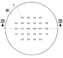
(光反射粉末を含む成形体2dを形成する工程)
次に、図3A、図3B、図4A、及び図4Bに示すように、透光部材1を取り囲むように透光部材1の側方に無機材料からなる光反射粉末を含む成形体2dを形成する。本実施形態では、複数の透光部材1それぞれを取り囲むように透光部材1のそれぞれの側面に成形体2dを形成している。
(Step of forming molded
Next, as shown in FIG. 3A, FIG. 3B, FIG. 4A and FIG. 4B, a molded
成形体2dは、スリップキャスト法、ドクターブレード法(シート成形法)、乾式成形法などを用いて成形することができる。ドクターブレード法を用いる場合は、具体的には、透光部材を覆うように添加剤を混ぜたスラリーをシート状に塗布した後に、スラリーがシート状に塗布されたグリーンシートを乾燥させて成形体を形成することができる。また、乾式成形法を用いる場合は、具体的には、透光部材を覆うように無機材料からなる光反射粉末を容器に充填し、光反射粉末を押圧することにより成形体を形成することができる。
The formed
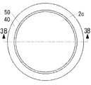
本実施形態では、スリップキャスト法により成形体2dを形成している。具体的には、まず、図3A及び図3Bに示すように、複数の透光部材1を取り囲む枠体50を支持部材40の上面に配置する。次に、枠体50の内側に光反射粉末を含むスラリー2cを塗布する。次に、スラリー2cに含まれる水分を石膏に吸わせる。石膏は水分を吸収する材料であるため、例えば室温で数時間程度放置すればよい。これにより、光反射粉末を含む成形体2dを形成している。このとき、透光部材1と成形体2dとは、完全に固着しているわけではないものの、一定の形に成形されている(以下、透光部材1と成形体2dとが一定の形に成形されたものを「複合体」という。)。スリップキャスト法を用いることにより、加圧せずに成形することができる。また、ドクターブレード法に比較してスラリーに含まれる有機物を少なくすることができる。これにより、成形密度を高くすることができるため、焼成時に光反射部材2にクラックが入る可能性を低減することができる。
In the present embodiment, the molded
枠体50としては、離形性及び撥水性を有するものを用いることができる。これにより、枠体50の内側面に成形体2dが固着することを低減することができる。また、スラリー2cに含まれる水分が枠体50に吸水されることを抑制することができるため、枠体50近傍における成形体2dの成形密度のむらを低減することができる。本実施形態では、フッ素樹脂からなる枠体50を用いている。
As the
本実施形態のスラリー2cは、酸化アルミニウム及び酸化イットリウムを含む光反射粉末、分散剤、結合剤、並びに純水を含んでいる。スラリー2cの厚みは透光部材1の厚みよりも大きいことが好ましい。すなわち、スラリー2cが透光部材1の側面のみならず上面まで被覆していることが好ましい。透光部材とスラリーとの厚みを同じにすることは難しいため、透光部材の厚みがスラリーよりも厚くなる場合がある。この場合、後に説明する得られた光学部品10の一部を除去する工程において、研磨等の際に透光部材のみに力が加わるため透光部材が破損するおそれがある。そこで、本実施形態では、厚みを大きくすることで、透光部材1のみに力が加わることを抑制している。スラリー2cの厚みは光学部品10の厚みに対して、2倍以上4倍以下とすることが好ましい。2倍以上とすることにより、透光部材1と成形体2dとの剥離を抑制することができるため、透光部材1及び成形体2dから支持部材40を除去しやすくすることができる。また、4倍以下とすることにより、得られた光学部品10の一部を除去する工程において、除去する光学部品10の厚みを小さくすることができる。
The
(支持部材40を除去する工程)
次に、図4A及び図4Bに示すように、透光部材1及び成形体2dから支持部材40を除去する。透光部材1と支持部材40とは樹脂により仮止めされているが、透光部材1の下面の面積は比較的小さい。また、透光部材1と成形体2dとはある程度一体的に成形されている。これらの理由により、加熱によって樹脂を軟下させたり、過度に力を入れて引っ張らなくとも透光部材1と支持部材40とを分離させることができる。本実施形態では、支持部材40の上面から枠体50を除去し、その後、複合体を支持部材40から外している。
(Step of removing support member 40)
Next, as shown in FIGS. 4A and 4B, the
(脱脂工程)
次に、複合体に含まれる有機物(分散剤及び結合剤)を除去するために、成形体2dを焼結する温度よりも低い温度で加熱する。脱脂工程は、例えば、窒素雰囲気や大気雰囲気で行うことができる。脱脂のための加熱は、確実に有機物を除去するために、3時間以上行うことが好ましい。本実施形態では、脱脂工程と成形体2dを焼結する工程とを別の工程で行っているが、成形体2dを焼結する工程において、低い温度で一定の時間脱脂を行い、そのまま温度を高くして成形体2dを焼結してもよい。なお、成形体2dを形成する工程において乾式成形法を用いる場合は、この工程は不要である。
(Degreasing process)
Next, in order to remove the organic matter (dispersant and binder) contained in the composite, the compact 2d is heated at a temperature lower than the temperature at which it is sintered. The degreasing step can be performed, for example, in a nitrogen atmosphere or an air atmosphere. The heating for degreasing is preferably performed for 3 hours or more in order to reliably remove the organic matter. In this embodiment, the degreasing step and the step of sintering the compact 2d are performed in separate steps, but in the step of sintering the compact 2d, degreasing is performed at a low temperature for a certain period of time, and the temperature is It may be raised to sinter the compact 2d. In addition, when using the dry-forming method in the process of forming the molded
(成形体2dを焼結する工程)
次に、光反射粉末の焼結体を含む光反射部材と透光部材とが一体に形成され、透光部材1及び光反射部材2を横切る一断面で、光反射部材2において透光部材1の近傍に複数の空隙が偏在するように成形体2dを焼結する。このような光反射部材2は、焼結温度や焼結時の加圧の程度で調整することができる。ここでは、図5A及び図5Bに示すように、成形体2dを押圧せずに焼結することにより、光反射粉末の焼結体と透光部材1とが一体になった光学部品10を得る。これにより、第1領域2aと、第2領域2bと、を透光部材1の側から順に有する光反射部材2を含む光学部品10とすることができる。第1領域2a及び第2領域2bは以下の理由で形成されていると考えられる。成形体2dを焼結する際に、光反射粉末は近くにある他の光反射粉末と結合しながら収縮する。このとき、透光部材1から遠い領域においては光反射粉末が全周にあるため、光反射粉末同士が結合しやすく気孔ができにくいが、透光部材1の近傍領域においては光反射粉末が外側にしかないため、光反射粉末同士が結合することができず気孔ができやすくなる。押圧せずに焼結することにより、このように光反射粉末同士が離れた状態が維持されたまま焼結が完了するため、透光部材1の近傍においては光反射部材2の気孔率が高くなると考えられる。
(Step of sintering the molded
Next, the light reflection member including the sintered body of the light reflection powder and the light transmission member are integrally formed, and the
蛍光体を含むセラミックスからなる透光部材1の周囲に、95.2重量%の酸化アルミニウムと4.8重量%の酸化イットリウムとを含む光反射粉末を有する成形体2dをスリップキャスト法により形成し、その後押圧せずに焼結した光学部品10を上面側から観察した二次電子像を図8Aに示す。二次電子像を測定する際には、二次電子像を測定するために蒸着によりカーボン膜を形成している。図8Aの第1領域2aは、第1領域2aに含まれる空隙に起因して第2領域2bよりも黒くなっている。また、図8Bに図8AのA領域のSEM画像を示し、図8Cに図8AのB領域のSEM画像を示す。図8Bでは透光部材1の近傍において気孔が多く存在しているのに対して、図8Cでは気孔がほぼなくなっている。これらの結果からわかるように、押圧することなく光反射粉末を焼結して光反射部材2を形成することにより、気孔率の異なる領域を有する光反射部材2を形成することができることを確認できた。
A molded
光反射性粉末として酸化アルミニウムを用いる場合は、焼結温度を、1200℃以上1800℃以下に設定することが好ましく、1400℃以上1500℃以下に設定することがより好ましい。1200℃以上に設定することにより、光反射部材2としての強度を確保することができる。また、1800℃以下に設定することにより、光反射部材2の透光性が高くなる可能性を低減することができる。
When aluminum oxide is used as the light reflective powder, the sintering temperature is preferably set to 1200 ° C. or more and 1800 ° C. or less, and more preferably set to 1400 ° C. or more and 1500 ° C. or less. By setting the temperature to 1200 ° C. or higher, the strength as the
本実施形態では、大気雰囲気下で焼結している。焼結時間は、例えば、30分以上5時間以下の範囲で設定することが好ましく、2時間以上4時間以下の範囲で設定することがより好ましい。30分以上とすることにより、光反射部材2の強度を確保しやすくすることができる。また、5時間以下とすることにより、必要以上に焼結に時間をかけることを避けることができる。
In the present embodiment, sintering is performed in the atmosphere. The sintering time is preferably set, for example, in the range of 30 minutes to 5 hours, and more preferably in the range of 2 hours to 4 hours. By setting it as 30 minutes or more, the intensity | strength of the
(光学部品10の一部を除去する工程)
この段階では、透光部材1の上面は光反射部材2で覆われている。そこで、図6A及び図6Bに示すように、透光部材1が露出するまで、光学部品10の上面側から光学部品10の一部を除去する。光学部品10の一部を除去する方法としては、研磨等が挙げられる。本実施形態は、一方側からのみ除去しているが、透光部材1の下面及び光反射部材2の下面の付着物を除去するために、さらに下面側から光学部品10の一部を除去してもよい。本実施形態では、透光部材1が多角柱状態であり、その角と接する部分には第1領域2aが無い、又は、上方から見て角と接する部分の第1領域2aの幅はそれ以外の部分の第1領域2aの幅よりも狭い。なお、本工程は必ずしも必要ではなく、例えば、成形体2dを焼結する工程で透光部材1の上面が光反射部材2の上面から露出した光学部品が得られている場合は本工程を省略してもよい。
(Step of removing a part of the optical component 10)
At this stage, the upper surface of the
(個片化する工程)
次に、図7A及び図7Bに示すように、1つの光学部品10が1つの透光部材1を含むように複数の光学部品10に個片化する。例えば、ブレードを用いて複数の光学部品10に個片化することができる。なお、本実施形態では、1つの光学部品10が1つの透光部材1を含むように個片化しているが、1つの光学部品10が複数の透光部材1を含むように個片化してもよい。また、本工程は必ずしも必要ではなく、例えば、成形体2dを焼結する工程又は光学部品10の一部を除去する工程で所望の光学部品10を得ることができている場合は、本工程を省略してもよい。
(Step of singulating)
Next, as shown in FIGS. 7A and 7B, one
<第2実施形態>
図9に、第2実施形態に係る光学部品20と発光素子60とを組み合わせた発光装置100の模式図を示す。光学部品20は、次に説明する事項以外は、光学部品10で説明した事項と実質的に同一である。
Second Embodiment
FIG. 9 shows a schematic view of a
光学部品20は、透光部材1の下面及び光反射部材2の下面の双方に、透光部材1側から順に絶縁膜5及びフィルタ4を介して、放熱部材3が設けられている。透光部材1の下面又は光反射部材2の下面の一方に放熱部材3を設けてもよいが、本実施形態のように、放熱性を考慮して両者に放熱部材3を設けることが好ましい。なお、透光部材1の上面及び光反射部材2の上面の少なくとも一方に放熱部材を設けることもできるが、本実施形態のように、透光部材1の下面及び光反射部材2の下面の少なくとも一方に透光性の放熱部材3が設けられていることが好ましい。透光部材1に放熱部材3を接合する際に、研磨等によって透光部材1の表面を平坦にする場合があるが、この場合に研磨等のレート差により光反射部材2の第1領域2aが、透光部材1や第2領域2bよりも優先して除去されることがあり、その結果、第1領域2aが部分的に凹んで、溝が形成されることがある。したがって、仮に、透光部材の上面及び光反射部材の上面の少なくとも一方に放熱部材を設けようとすると、光取出し側となる上方において、第1領域にできた溝から光が抜けるため輝度が低下するおそれがある。そこで、本実施形態のように、透光部材1の下面及び光反射部材2の下面の少なくとも一方に放熱部材3を設けることが好ましい。
In the
光学部品20においては、透光部材1で生じる熱を放熱部材3に排熱することができるため、透光部材1の劣化を低減することができる。
In the
本実施形態では、フィルタ4として、発光素子60からの光を透過しやすく、透光部材1の蛍光を反射しやすいものを用いている。本実施形態では、発光素子60として青色光を発するものを用いており、透光部材1として青色光が照射されることにより黄色光を発する蛍光体を含むものを用いている。したがって、青色光を透過しやすく黄色光を反射しやすいフィルタ4を用いている。
In the present embodiment, as the filter 4, a filter which easily transmits light from the
本実施形態では、フィルタ4と透光部材1の下面及び光反射部材2の下面とは絶縁膜5を介して接合されている。本実施形態では、フィルタ4と透光部材1等とを表面活性化接合法により接合するために、透光部材1の下面および光反射部材2の下面を研磨している。このとき、透光部材1と光反射部材2と研磨レートの差により、透光部材1と光反射部材2との境目の近傍に溝ができる。溝があるまま表面活性化接合法を行うと、透光部材1と放熱部材3との間に隙間ができるため、放熱性が低下するおそれがある。このため、絶縁膜5で溝を埋めて、放熱性の低下を低減している。
In the present embodiment, the filter 4 and the lower surface of the
本実施形態では、絶縁膜5として、酸化アルミニウムを用いている。この他にも、例えば、酸化ケイ素、酸化チタンを用いることができる。絶縁膜5は、放熱性の低下を抑制するために、溝を埋める程度の膜厚で形成することが好ましい。なお、本実施形態では表面活性化接合法によりフィルタ4と透光部材1とを接合しているが、原子拡散接合法を用いて接合してもよい。この場合は、フィルタの上面と透光部材の下面とにそれぞれ金属膜を形成し、金属膜同士を接合することにより、フィルタと透光部材とを接合する。
In the present embodiment, aluminum oxide is used as the insulating film 5. Besides this, for example, silicon oxide and titanium oxide can be used. The insulating film 5 is preferably formed to have a film thickness enough to fill the groove in order to suppress a decrease in heat dissipation. Although the filter 4 and the
図9に示す発光装置100では、発光素子60としてレーザ素子(Laser Diode、LD)を用いている。LDは、LDからの光が光学部品20に含まれる透光部材1を通過するように、光学部品20と離間して配置されている。透光部材1として蛍光体を含む蛍光体セラミックスを用い、且つ、発光素子60としてLDを用いる場合は、透光部材1からの排熱の必要性が増す。このため、放熱部材3を設けることによる排熱性向上の効果がより顕著となる。
In the
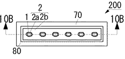
<第3実施形態>
図10Aに、第3実施形態に係る光学部品30と発光素子60とを組み合わせた発光装置200の上面図を示し、図10Bに図10Aの10B−10B線における断面図を示す。光学部品30は、次に説明する事項以外は、光学部品10で説明した事項と実質的に同一である。
Third Embodiment
FIG. 10A shows a top view of a
光学部品30は、1つの光学部品30に複数の透光部材1が含まれている。そして、光反射部材2は、各透光部材1の周囲に第1領域2aを有し、その外側に第2領域2bを有している。
The
図10A及び図10Bに示す発光装置200では、基板70の上面に複数の発光素子60が設けられている。発光装置200では、発光素子60として発光ダイオード(Light Emitting Diode,LED)が用いられている。そして、1つの発光素子60の上面に1つの透光部材1が位置するように、複数の発光素子60の上面に1つの光学部品30が配置されている。また、発光素子60の周囲には光反射性樹脂80が配置されている。
In the
発光装置200では、1つの発光素子60からの光が1つの透光部材1を通過するように配置しているが、2以上の発光素子からの光が1つの透光部材を通過するように光学部品及び発光素子を配置してもよい。
In the
<実施例>
以下の製造方法により光学部品を作製した。まず、透光部材1として、短辺が500μm、長辺が1000μm、高さが600μmの直方体の蛍光体セラミックスを準備した。蛍光体セラミックスとしては、YAG蛍光体と酸化アルミニウムとを含む、焼結体からなる蛍光体セラミックスを用いた。
<Example>
An optical component was produced by the following production method. First, a rectangular parallelepiped phosphor ceramic having a short side of 500 μm, a long side of 1000 μm, and a height of 600 μm was prepared as the
次に、スリップキャスト法により成形体2dを形成した。具体的には、以下の方法により成形体2dを形成した。まず、アクリル系の樹脂シートに蛍光体セラミックスを配置し、加圧することにより蛍光体セラミックスの下面にアクリル系の樹脂を転写した。そして、支持部材40である石膏の上面に樹脂を介して蛍光体セラミックスの下面を仮止めした。そして、蛍光体セラミックスを取り囲むように、支持部材40の上面に内径が30mmのテフロン(登録商標)リングからなる枠体50を固定した。次に、透光部材1の上面が見えなくなるまで枠体50の内側にスラリー2cを充填した。スラリー2cとしては、光反射粉末を76.4%、分散剤を0.7%、結合剤を2.4%、純水を20.5%含むものを用いた。光反射粉末は、95.2重量%の酸化アルミニウムと、4.8重量%の酸化イットリウムと、を含む。また、分散剤はポリカルボン酸アンモニウム系の材料を含み、結合剤としてはアクリル系の材料を含む。そして、1晩放置して、スラリー2cに含まれる水分を石膏に吸わせることにより、成形体2dを形成した。つまり、蛍光体セラミックスと成形体2dとが一定の形に成形された複合体を形成した。
Next, a formed
次に、枠体50を外した後に、複合体を支持部材40から外した。このとき、蛍光体セラミックスの下面と石膏とは接着剤により仮止めされているが、蛍光体セラミックスの下面の面積が比較的小さいため複合体を支持部材40から外すことができる。そして、複合体を、窒素雰囲気下で700℃で3時間加熱することにより脱脂した。次に、1450℃で2時間焼成した。これにより、蛍光体セラミックスと光反射部材2とが一体になっており、蛍光体セラミックスの側面及び上面が光反射部材2に覆われた光学部品を得た。次に、得られた光学部品を蛍光体セラミックスの上面が露出するまで上面側から研磨した。これにより、上方から見て、蛍光体セラミックスが光反射部材2に取り囲まれた光学部品が得られた。
Next, after the
得られた光学部品について、落射型の顕微鏡を用いて暗視野観察を行った写真を図11に示す。図11において、中心にある長方形の部材が透光部材1であり、その外側にあるのが光反射部材2である。光反射部材2において、黒色の部分が第1領域2aであり、その外側の領域が第2領域2bである。図11に示すように、第1領域2aでは、気孔率が高いことから気孔に起因して影になって写る部分が多いために黒色に見えており、第2領域2bは気孔率が低いため影が少なく色が付いていないと考えられる。
About the obtained optical component, the photograph which performed the dark field observation using the incident type microscope is shown in FIG. In FIG. 11, the rectangular member at the center is the
各実施形態に記載の光学部品は、照明、車両用灯具等に使用することができる。 The optical component described in each embodiment can be used for lighting, a vehicle lamp, and the like.
1…透光部材
2…光反射部材
2a…第1領域
2b…第2領域
2c…スラリー
2d…成形体
3…放熱部材
4…フィルタ
5…絶縁膜
10、20、30…光学部品
40…支持部材
50…枠体
60…発光素子
70…基板
80…光反射性樹脂
100、200…発光装置
DESCRIPTION OF
Claims (12)
前記透光部材を取り囲むように前記透光部材の側方に設けられた光反射部材と、を備え、
前記光反射部材は、複数の空隙を含むセラミックスからなり、
前記透光部材及び前記光反射部材を横切る一断面において、前記複数の空隙は前記透光部材の近傍に偏在していることを特徴とする光学部品。 A translucent member having an upper surface, a lower surface and a side surface;
A light reflecting member provided on a side of the light transmitting member so as to surround the light transmitting member;
The light reflecting member is made of a ceramic including a plurality of air gaps,
An optical component characterized in that the plurality of air gaps are unevenly distributed in the vicinity of the light transmitting member in a cross section crossing the light transmitting member and the light reflecting member.
前記透光部材を取り囲むように前記透光部材の側方に無機材料からなる光反射粉末を含む成形体を形成する工程と、
前記光反射粉末の焼結体を含む光反射部材と前記透光部材とが一体に形成され、前記透光部材及び前記光反射部材を横切る一断面で、前記光反射部材において前記透光部材の近傍に複数の空隙が偏在するように前記成形体を焼結する工程と、を有する光学部品の製造方法。 Providing a translucent member having an upper surface, a lower surface, and a side surface;
Forming a compact including a light reflecting powder made of an inorganic material on the side of the light transmitting member so as to surround the light transmitting member;
A light reflecting member including a sintered body of the light reflecting powder and the light transmitting member are integrally formed, and the light reflecting member is formed of the light reflecting member in a section crossing the light transmitting member and the light reflecting member. Sintering the compact so that a plurality of voids are unevenly distributed in the vicinity.
前記成形体を形成する工程において、前記複数の透光部材それぞれを取り囲むように前記透光部材それぞれの側方に前記成形体を形成することを特徴とする請求項7〜10のいずれか1項に記載の光学部品の製造方法。 In the step of preparing the translucent member, a plurality of translucent members are prepared,
The process of forming the said molded object WHEREIN: The said molded object is formed in the side of each of the said light transmission member so that each of the said some light transmission member may be surrounded, The said any one of the Claims 7-10 The manufacturing method of the optical component as described in.
前記成形体を形成する工程と前記成形体を焼結する工程との間に、前記透光部材及び前記成形体から前記支持部材を除去する工程を有することを特徴とする請求項7〜11のいずれか1項に記載の光学部品の製造方法。 The step of temporarily fixing the light transmitting member to the support member between the step of preparing the light transmitting member and the step of forming the molded body, and only between the light transmitting member and the support member Providing a resin and temporarily fixing the light transmitting member to the support member;
12. The method according to claim 7, further comprising the step of removing the support member from the light transmitting member and the compact between the step of forming the compact and the step of sintering the compact. The manufacturing method of the optical component of any one term.
Priority Applications (9)
| Application Number | Priority Date | Filing Date | Title |
|---|---|---|---|
| EP19204255.4A EP3633804B1 (en) | 2017-03-03 | 2018-03-02 | Light emitting device |
| EP18159660.2A EP3370308B1 (en) | 2017-03-03 | 2018-03-02 | Optical component and method of manufacturing same |
| EP21168341.2A EP3869638A1 (en) | 2017-03-03 | 2018-03-02 | Optical component |
| CN201810173995.XA CN108535797A (en) | 2017-03-03 | 2018-03-02 | The manufacturing method of optical component and optical component |
| US15/910,921 US10670200B2 (en) | 2017-03-03 | 2018-03-02 | Optical component and method of manufacturing same |
| CA2997327A CA2997327A1 (en) | 2017-03-03 | 2018-03-05 | Optical component and method of manufacturing same |
| JP2019104439A JP6912737B2 (en) | 2017-03-03 | 2019-06-04 | Optical parts and manufacturing method of optical parts |
| US16/860,303 US10859216B2 (en) | 2017-03-03 | 2020-04-28 | Optical component and method of manufacturing same |
| US17/087,827 US11162645B2 (en) | 2017-03-03 | 2020-11-03 | Light emitting device including heat dissipation member |
Applications Claiming Priority (4)
| Application Number | Priority Date | Filing Date | Title |
|---|---|---|---|
| JP2017040495 | 2017-03-03 | ||
| JP2017040495 | 2017-03-03 | ||
| JP2017125738 | 2017-06-28 | ||
| JP2017125738 | 2017-06-28 |
Related Child Applications (1)
| Application Number | Title | Priority Date | Filing Date |
|---|---|---|---|
| JP2019104439A Division JP6912737B2 (en) | 2017-03-03 | 2019-06-04 | Optical parts and manufacturing method of optical parts |
Publications (2)
| Publication Number | Publication Date |
|---|---|
| JP2019009406A JP2019009406A (en) | 2019-01-17 |
| JP6544408B2 true JP6544408B2 (en) | 2019-07-17 |
Family
ID=65029757
Family Applications (3)
| Application Number | Title | Priority Date | Filing Date |
|---|---|---|---|
| JP2017204385A Active JP6544408B2 (en) | 2017-03-03 | 2017-10-23 | Optical component and method of manufacturing optical component |
| JP2019104439A Active JP6912737B2 (en) | 2017-03-03 | 2019-06-04 | Optical parts and manufacturing method of optical parts |
| JP2021112541A Active JP7157356B2 (en) | 2017-03-03 | 2021-07-07 | Optical component and method for manufacturing optical component |
Family Applications After (2)
| Application Number | Title | Priority Date | Filing Date |
|---|---|---|---|
| JP2019104439A Active JP6912737B2 (en) | 2017-03-03 | 2019-06-04 | Optical parts and manufacturing method of optical parts |
| JP2021112541A Active JP7157356B2 (en) | 2017-03-03 | 2021-07-07 | Optical component and method for manufacturing optical component |
Country Status (1)
| Country | Link |
|---|---|
| JP (3) | JP6544408B2 (en) |
Families Citing this family (8)
| Publication number | Priority date | Publication date | Assignee | Title |
|---|---|---|---|---|
| JP7323763B2 (en) | 2018-12-27 | 2023-08-09 | 日亜化学工業株式会社 | Light-emitting device and method for manufacturing light-emitting device |
| US11205886B2 (en) | 2019-03-12 | 2021-12-21 | Nichia Corporation | Method of manufacturing optical member, optical member, and light emitting device |
| JP7111989B2 (en) | 2019-04-22 | 2022-08-03 | 日亜化学工業株式会社 | Wavelength conversion component, method for manufacturing wavelength conversion component, and light emitting device |
| JP7189446B2 (en) * | 2019-08-08 | 2022-12-14 | 日亜化学工業株式会社 | Light-emitting device and method for manufacturing light-emitting device |
| JP2021152615A (en) * | 2020-03-24 | 2021-09-30 | スタンレー電気株式会社 | Optical device |
| JP2021173925A (en) | 2020-04-28 | 2021-11-01 | 日亜化学工業株式会社 | Wavelength conversion member and method of manufacturing light-emitting device |
| CN112486021B (en) * | 2020-12-07 | 2021-10-08 | 燕山大学 | Low-complexity control method for asymmetric servo hydraulic position tracking system |
| US20230318254A1 (en) | 2022-03-31 | 2023-10-05 | Nichia Corporation | Phosphor member, method of manufacturing phosphor member, and light-emitting device |
Family Cites Families (10)
| Publication number | Priority date | Publication date | Assignee | Title |
|---|---|---|---|---|
| WO2006097876A1 (en) * | 2005-03-14 | 2006-09-21 | Koninklijke Philips Electronics N.V. | Phosphor in polycrystalline ceramic structure and a light-emitting element comprising same |
| WO2011039911A1 (en) * | 2009-10-02 | 2011-04-07 | シャープ株式会社 | Organic el lighting device and manufacturing method therefor |
| JP5695887B2 (en) * | 2010-11-18 | 2015-04-08 | スタンレー電気株式会社 | Light source device and lighting device |
| JP5917183B2 (en) * | 2012-02-17 | 2016-05-11 | スタンレー電気株式会社 | Light source device and lighting device |
| US8931922B2 (en) * | 2012-03-22 | 2015-01-13 | Osram Sylvania Inc. | Ceramic wavelength-conversion plates and light sources including the same |
| JP2013207049A (en) * | 2012-03-28 | 2013-10-07 | Nec Corp | Light emitting device using wavelength conversion body |
| JP6323020B2 (en) * | 2014-01-20 | 2018-05-16 | セイコーエプソン株式会社 | Light source device and projector |
| JP2016027613A (en) * | 2014-05-21 | 2016-02-18 | 日本電気硝子株式会社 | Wavelength conversion member and light emitting device using the same |
| JP2016058624A (en) * | 2014-09-11 | 2016-04-21 | パナソニックIpマネジメント株式会社 | Light-emitting device |
| JP2016213451A (en) * | 2015-05-01 | 2016-12-15 | 日東電工株式会社 | Manufacturing method for optical semiconductor element with phosphor layer-sealing layer |
-
2017
- 2017-10-23 JP JP2017204385A patent/JP6544408B2/en active Active
-
2019
- 2019-06-04 JP JP2019104439A patent/JP6912737B2/en active Active
-
2021
- 2021-07-07 JP JP2021112541A patent/JP7157356B2/en active Active
Also Published As
| Publication number | Publication date |
|---|---|
| JP2019164376A (en) | 2019-09-26 |
| JP2021184093A (en) | 2021-12-02 |
| JP7157356B2 (en) | 2022-10-20 |
| JP6912737B2 (en) | 2021-08-04 |
| JP2019009406A (en) | 2019-01-17 |
Similar Documents
| Publication | Publication Date | Title |
|---|---|---|
| JP6544408B2 (en) | Optical component and method of manufacturing optical component | |
| TWI673252B (en) | Wavelength converting member and light emitting device using same | |
| US11162645B2 (en) | Light emitting device including heat dissipation member | |
| KR102576303B1 (en) | Wavelength conversion member and light-emitting device | |
| JP2012104267A (en) | Light source device and lighting system | |
| WO2018016357A1 (en) | Wavelength conversion member and light-emitting device using same | |
| US20170137328A1 (en) | Method of making a ceramic wavelength converter assembly | |
| JP2016157905A (en) | Optical component | |
| KR20180095645A (en) | Wavelength converting member and light emitting device | |
| US10185213B2 (en) | Fluorescent substrate, light source device, and projection display unit | |
| WO2017040433A1 (en) | Laser-activated remote phosphor target and system | |
| US20140166902A1 (en) | Wavelength Conversion Body And Method For Manufacturing Same | |
| JP5781367B2 (en) | Light source device and lighting device | |
| JP7189422B2 (en) | WAVELENGTH CONVERSION MEMBER COMPOSITE, LIGHT-EMITTING DEVICE, AND METHOD OF MANUFACTURING WAVELENGTH CONVERSION MEMBER COMPOSITE | |
| US20230299248A1 (en) | Optical member, light-emitting device, method for manufacturing optical member, and method for manufacturing light-emitting device | |
| WO2023166638A1 (en) | Composite ceramic, phosphor element, laser illumination device, and method for manufacturing composite element | |
| WO2021132212A1 (en) | Wavelength conversion member, light-emitting element, and light-emitting device | |
| JP7053984B2 (en) | Manufacturing method of optical parts and light emitting device, as well as optical parts and light emitting device | |
| JP2018107006A (en) | Light-emitting element and fluorescent light source device |
Legal Events
| Date | Code | Title | Description |
|---|---|---|---|
| RD03 | Notification of appointment of power of attorney |
Free format text: JAPANESE INTERMEDIATE CODE: A7423 Effective date: 20171115 |
|
| A621 | Written request for application examination |
Free format text: JAPANESE INTERMEDIATE CODE: A621 Effective date: 20180403 |
|
| A977 | Report on retrieval |
Free format text: JAPANESE INTERMEDIATE CODE: A971007 Effective date: 20190426 |
|
| TRDD | Decision of grant or rejection written | ||
| A01 | Written decision to grant a patent or to grant a registration (utility model) |
Free format text: JAPANESE INTERMEDIATE CODE: A01 Effective date: 20190521 |
|
| A61 | First payment of annual fees (during grant procedure) |
Free format text: JAPANESE INTERMEDIATE CODE: A61 Effective date: 20190603 |
|
| R150 | Certificate of patent or registration of utility model |
Ref document number: 6544408 Country of ref document: JP Free format text: JAPANESE INTERMEDIATE CODE: R150 |
|
| R250 | Receipt of annual fees |
Free format text: JAPANESE INTERMEDIATE CODE: R250 |