WO2023166590A1 - 光増幅器及び光増幅方法 - Google Patents
光増幅器及び光増幅方法 Download PDFInfo
- Publication number
- WO2023166590A1 WO2023166590A1 PCT/JP2022/008781 JP2022008781W WO2023166590A1 WO 2023166590 A1 WO2023166590 A1 WO 2023166590A1 JP 2022008781 W JP2022008781 W JP 2022008781W WO 2023166590 A1 WO2023166590 A1 WO 2023166590A1
- Authority
- WO
- WIPO (PCT)
- Prior art keywords
- optical
- amplifier
- amplification
- signal
- optical parametric
- Prior art date
- Legal status (The legal status is an assumption and is not a legal conclusion. Google has not performed a legal analysis and makes no representation as to the accuracy of the status listed.)
- Ceased
Links
Images





Classifications
-
- H—ELECTRICITY
- H01—ELECTRIC ELEMENTS
- H01S—DEVICES USING THE PROCESS OF LIGHT AMPLIFICATION BY STIMULATED EMISSION OF RADIATION [LASER] TO AMPLIFY OR GENERATE LIGHT; DEVICES USING STIMULATED EMISSION OF ELECTROMAGNETIC RADIATION IN WAVE RANGES OTHER THAN OPTICAL
- H01S3/00—Lasers, i.e. devices using stimulated emission of electromagnetic radiation in the infrared, visible or ultraviolet wave range
- H01S3/30—Lasers, i.e. devices using stimulated emission of electromagnetic radiation in the infrared, visible or ultraviolet wave range using scattering effects, e.g. stimulated Brillouin or Raman effects
-
- H—ELECTRICITY
- H01—ELECTRIC ELEMENTS
- H01S—DEVICES USING THE PROCESS OF LIGHT AMPLIFICATION BY STIMULATED EMISSION OF RADIATION [LASER] TO AMPLIFY OR GENERATE LIGHT; DEVICES USING STIMULATED EMISSION OF ELECTROMAGNETIC RADIATION IN WAVE RANGES OTHER THAN OPTICAL
- H01S3/00—Lasers, i.e. devices using stimulated emission of electromagnetic radiation in the infrared, visible or ultraviolet wave range
- H01S3/10—Controlling the intensity, frequency, phase, polarisation or direction of the emitted radiation, e.g. switching, gating, modulating or demodulating
- H01S3/10007—Controlling the intensity, frequency, phase, polarisation or direction of the emitted radiation, e.g. switching, gating, modulating or demodulating in optical amplifiers
- H01S3/10023—Controlling the intensity, frequency, phase, polarisation or direction of the emitted radiation, e.g. switching, gating, modulating or demodulating in optical amplifiers by functional association of additional optical elements, e.g. filters, gratings, reflectors
- H01S3/1003—Controlling the intensity, frequency, phase, polarisation or direction of the emitted radiation, e.g. switching, gating, modulating or demodulating in optical amplifiers by functional association of additional optical elements, e.g. filters, gratings, reflectors tunable optical elements, e.g. acousto-optic filters, tunable gratings
-
- H—ELECTRICITY
- H01—ELECTRIC ELEMENTS
- H01S—DEVICES USING THE PROCESS OF LIGHT AMPLIFICATION BY STIMULATED EMISSION OF RADIATION [LASER] TO AMPLIFY OR GENERATE LIGHT; DEVICES USING STIMULATED EMISSION OF ELECTROMAGNETIC RADIATION IN WAVE RANGES OTHER THAN OPTICAL
- H01S3/00—Lasers, i.e. devices using stimulated emission of electromagnetic radiation in the infrared, visible or ultraviolet wave range
- H01S3/23—Arrangements of two or more lasers not provided for in groups H01S3/02 - H01S3/22, e.g. tandem arrangements of separate active media
- H01S3/2308—Amplifier arrangements, e.g. MOPA
-
- H—ELECTRICITY
- H01—ELECTRIC ELEMENTS
- H01S—DEVICES USING THE PROCESS OF LIGHT AMPLIFICATION BY STIMULATED EMISSION OF RADIATION [LASER] TO AMPLIFY OR GENERATE LIGHT; DEVICES USING STIMULATED EMISSION OF ELECTROMAGNETIC RADIATION IN WAVE RANGES OTHER THAN OPTICAL
- H01S3/00—Lasers, i.e. devices using stimulated emission of electromagnetic radiation in the infrared, visible or ultraviolet wave range
- H01S3/30—Lasers, i.e. devices using stimulated emission of electromagnetic radiation in the infrared, visible or ultraviolet wave range using scattering effects, e.g. stimulated Brillouin or Raman effects
- H01S3/302—Lasers, i.e. devices using stimulated emission of electromagnetic radiation in the infrared, visible or ultraviolet wave range using scattering effects, e.g. stimulated Brillouin or Raman effects in an optical fibre
-
- H—ELECTRICITY
- H04—ELECTRIC COMMUNICATION TECHNIQUE
- H04B—TRANSMISSION
- H04B10/00—Transmission systems employing electromagnetic waves other than radio-waves, e.g. infrared, visible or ultraviolet light, or employing corpuscular radiation, e.g. quantum communication
- H04B10/29—Repeaters
- H04B10/291—Repeaters in which processing or amplification is carried out without conversion of the main signal from optical form
Definitions
- the present invention relates to an optical amplifier and an optical amplification method.
- Broadband transmission systems for conventional optical amplification and transmission systems have been achieved by using rare-earth-doped fiber amplifiers (EDFA (Erbium Doped Fiber Amplifier), BDFA (Bithmus Doped Fiber Amplifier), etc.) and semiconductor optical amplifiers (SOA: (Semiconductor Optical Amplifier), and in some cases, it is realized in combination with backward-pumping distributed Raman amplification that can control the amplification band with the pumping light wavelength that uses the transmission line itself as the amplification medium.
- EDFA Erbium Doped Fiber Amplifier
- BDFA Bithmus Doped Fiber Amplifier
- SOA semiconductor optical amplifier
- Rare-earth-doped optical fiber amplifiers and semiconductor optical amplifiers are expected to increase or decrease the number of wavelengths because there is concern that rapid fluctuations in input optical signal power will cause optical surges, degrading signal quality and damaging optical components. There was a problem in applying it to a future optical network that utilizes abundant wavelength resources.
- optical parametric amplification which is capable of amplifying polarization multiplexed signals and has excellent broadband characteristics and high-speed responsiveness, to optical amplifier repeaters has been studied (see, for example, Non-Patent Document 2).
- the optical signal is not distorted in the operating region where the gain is saturated.
- the gain fluctuates according to the magnitude of the amplitude component of the signal, causing distortion in the signal. Therefore, it is difficult for an optical parametric amplifier to achieve both high gain and high output.
- the signal-to-noise ratio is improved by increasing the input power to the transmission line fiber, the signal will be distorted due to gain saturation in the optical parametric amplifier. Poor signal quality. Therefore, there is a problem that the signal quality after amplification is limited in the wide amplification band covered by the optical parametric amplifier.
- One aspect of the present invention is an optical amplifier that optically amplifies and repeats an optical signal transmitted through an optical fiber transmission line, comprising: an optical parametric amplifier that performs optical parametric amplification on an input optical signal; and the optical fiber transmission line.
- a Raman amplifier for controlling a gain so as to shift the optimum input optical power in the optical parametric amplifier to a region where the output of the optical parametric amplifier is linearly amplified.
- One aspect of the present invention is an optical amplification method in an optical amplifier that optically amplifies and repeats an optical signal transmitted through an optical fiber transmission line, wherein an optical parametric amplifier performs optical parametric amplification on an input optical signal,
- the gain is controlled such that the optimum input optical power in the optical fiber transmission line is shifted to a region where the output of the optical parametric amplifier is linearly amplified.
- optical amplifying repeaters it is possible to perform broadband and high-quality optical amplifying repeaters in optical amplifying repeaters using optical parametric amplification.
- FIG. 1 is a diagram showing a configuration example of an optical transmission system according to the present invention
- FIG. 1 is a diagram for explaining a basic configuration example of an optical amplifier according to the present invention
- FIG. FIG. 4 is a diagram for explaining the effect of combining optical parametric amplification and forward-pumped Raman amplification
- FIG. 4 is a diagram for explaining the effect of combining optical parametric amplification and forward-pumped Raman amplification
- 1 is a diagram illustrating a configuration example of an optical amplifier according to a first embodiment
- FIG. 4 is a flow chart showing the flow of processing performed by the optical amplifier in the first embodiment
- FIG. 10 is a diagram illustrating a configuration example of an optical amplifier according to a second embodiment
- FIG. 9 is a flow chart showing the flow of processing performed by the optical amplifier in the second embodiment; It is a figure for demonstrating the effect in 1st Embodiment and 2nd Embodiment.
- FIG. 12 is a diagram illustrating a configuration example of an optical amplifier according to a third embodiment; FIG.
- FIG. 1 is a diagram showing a configuration example of an optical transmission system 100 according to the present invention.
- the optical transmission system 100 includes a plurality of optical transmitters 10-1 to 10-N (N is an integer equal to or greater than 2), an optical multiplexer/demultiplexer 20, an optical amplifying repeater transmission line 30, an optical multiplexer/demultiplexer 40, A plurality of optical receivers 50-1 to 50-N are provided.
- the optical amplifying repeater transmission line 30 is configured using one or more optical amplifiers 31 and an optical fiber transmission line.
- the optical transmitters 10-1 to 10-N transmit optical signals with different wavelengths.
- the optical transmitter 10-1 transmits an optical signal of wavelength 1
- the optical transmitter 10-N transmits an optical signal of wavelength N.
- FIG. 1 is a diagrammatic representation of the optical transmitter 10-1 to 10-N.
- the optical multiplexer/demultiplexer 20 multiplexes optical signals of different wavelengths transmitted from the optical transmitters 10-1 to 10-N by wavelength division multiplexing to generate a WDM signal.
- the optical multiplexer/demultiplexer 20 outputs the generated WDM signal to the optical amplification repeater transmission line 30 .
- the optical amplifier 31 amplifies and transmits the WDM signal output from the optical multiplexer/demultiplexer 20 . More specifically, the optical amplifier 31 performs optical parametric amplification and Raman amplification on the WDM signal.
- the optical multiplexer/demultiplexer 40 demultiplexes the WDM signal amplified by the optical amplifier 31 .
- the optical multiplexer/demultiplexer 40 demultiplexes a WDM signal into optical signals of wavelengths 1 to N and outputs the optical signals to the optical receivers 50-1 to 50-N.
- the optical receivers 50 - 1 to 50 -N receive optical signals demultiplexed by the optical multiplexer/demultiplexer 40 .
- the optical receiver 50-1 receives an optical signal of wavelength 1
- the optical receiver 50-N receives an optical signal of wavelength N.
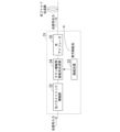
- FIG. 2 is a diagram for explaining a basic configuration example of the optical amplifier 31 in the present invention.
- the optical amplifier 31 includes an optical parametric amplification section 32 , a pumping light source 33 , a pumping light multiplexing section 34 for Raman amplification, and an optical isolator 35 .
- the optical parametric amplifier 32 is composed of, for example, a highly nonlinear fiber and a periodically poled lithium niobate (PPLN) waveguide.
- PPLN periodically poled lithium niobate
- the excitation light source 33 outputs excitation light with a predetermined wavelength and intensity.
- the wavelength of the pumping light output by the pumping light source 33 is set based on the wavelength of the optical signal input to the optical amplifier 31 .
- the Raman amplification pumping light multiplexing unit 34 performs forward pumping Raman amplification based on the optical signal amplified by the optical parametric amplification unit 32 and the pumping light output from the pumping light source 33 .
- the Raman amplification pumping light combiner 34 controls the gain so as to shift the optimum input light power in the optical fiber transmission line to a region where the output of the optical parametric amplifier 32 is linearly amplified.
- the optical isolator 35 transmits forward light and blocks backward light.
- the optical isolator 35 transmits light proceeding to the optical fiber transmission line and blocks light input in the direction of the Raman amplification pumping light combiner 34 .
- FIG. 3 shows a measurement example of the relationship between the optical signal quality (SNR) and the optical fiber input power when optically amplified relay transmission is carried out over 2,000 km with the configuration of the amplifier shown in the legend.
- FIG. 4 shows the results of comparison between the conventional configuration and the present invention regarding the gain/noise figure, input wavelength number (power) variation characteristics, and broadband characteristics.
- the configuration shown in FIG. 2 is that of an optical amplifier 31 capable of amplifying and repeating an optical signal of one wavelength. will be described.
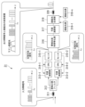
- FIG. 5 is a diagram showing a configuration example of the optical amplifier 31 in the first embodiment.
- the optical amplifier 31 includes an optical isolator 311, a band-splitting filter 312, a plurality of variable attenuators 313-1 and 313-2, a plurality of OPAs 314-1 and 314-2, and a plurality of monitors 315-1 and 315- 2, a band synthesizing/gain equalizing unit 316, a variable attenuation unit 317, a plurality of pumping light sources 318-1 to 318-n (n is an integer of 2 or more), a pumping light combining unit 319, and an optical isolator 320.
- a WDM signal is input to the optical amplifier 31 .
- the configuration shown in FIG. 5 can be applied as an optical amplifying repeater and a post-amplifier.
- the optical isolator 311 transmits forward light and blocks backward light.
- optical isolator 311 transmits light traveling to band-splitting filter 312 and blocks the input of light in the direction toward the optical fiber transmission line.
- Band splitting filter 312 splits the input WDM signal into two bands. Specifically, the band splitting filter 312 splits the WDM signal into a long wavelength band optical signal and a short wavelength band optical signal, for example, based on the fundamental wavelength ⁇ F . By the band splitting filter 312, the optical signal in the long wavelength band is output to the variable attenuator 313-1, and the optical signal in the short wavelength band is output to the variable attenuator 313-2.
- the phase conjugate light (idler light) generated around the fundamental wavelength ⁇ F in the process of optical parametric amplification is unnecessary. and amplified with OPA314-1 and 314-2.
- the pump light for distributed Raman amplification is included in the input signal (WDM signal), the band-splitting filter 312 and the pump light elimination filter shown in FIG. The pump light for Raman amplification is separated/removed from the WDM signal.
- variable attenuator 313-1 adjusts the power of the optical signal in the long wavelength band.
- the amount of attenuation by variable attenuator 313-1 is set based on the monitor 315-1 output power output power output from OPA 314-1. The power of the optical signal is adjusted.
- variable attenuator 313-2 adjusts the power of the optical signal in the short wavelength band.
- the amount of attenuation by variable attenuator 313-2 is set based on the monitor 315-2 output power output power output from OPA 314-2. The power of the optical signal is adjusted.
- the OPA314-1 is composed of, for example, a highly nonlinear fiber and a periodically poled lithium niobate (PPLN) waveguide.
- the OPA 314-1 amplifies the input optical signal using the nonlinear optical effect.
- OPA 314-1 amplifies WDM signals in the long wavelength band.
- the OPA 314-1 sets the pumping light level of the OPA 314-1 based on the monitor 315-1 monitoring the output power of the OPA 314-1, and performs amplification at the set pumping light level.
- the OPA314-2 is composed of, for example, a highly nonlinear fiber and a periodically poled lithium niobate waveguide.
- the OPA 314-2 amplifies the input optical signal using the nonlinear optical effect.
- OPA 314-2 amplifies WDM signals in the short wavelength band.
- the OPA 314-2 sets the pumping light level of the OPA 314-2 based on the result of monitoring the output power of the OPA 314-2 by the monitor 315-2, and performs amplification at the set pumping light level.
- the monitors 315-1 and 315-2 monitor the output power of the OPA's 314-1 and 314-2 in order to control the gain saturation of the OPA's 314-1 and 314-2.
- the operation region where gain saturation occurs with respect to pumping light and input signal power of OPAs 314-1 and 314-2 can be obtained by measuring in advance or by detecting distortion in the receiver of the optical transmission system. can.
- the band synthesizing/gain equalizing unit 316 synthesizes the long wavelength band WDM signal whose optical power is amplified by the OPA 314-1 and the short wavelength band WDM signal whose optical power is amplified by the OPA 314-2. After that, band synthesis/gain equalization section 316 performs gain equalization.
- variable attenuation section 317 adjusts the input power of the WDM signal output from the band synthesis/gain equalization section 316 .
- the excitation light sources 318-1 to 318-n output excitation light of different wavelengths.
- the pumping light sources 318-1 to 318-n have a wavelength band shifted to the short wavelength side by about 100 nm with respect to the WDM signal.
- an incoherent light source in a multi-repeater transmission or high Raman amplification gain region.
- a plurality of wavelengths may be bundled including a light source for polarization multiplexing and secondary excitation.
- the forward-pumped Raman amplification gain is set at the pump source output such that the optimum optical fiber input power falls within the non-gain-saturated regions of OPAs 314-1 and 314-2.
- the excitation light multiplexing unit 319 multiplexes the excitation light output from each of the excitation light sources 318-1 to 318-n and the WDM signal.
- the optical isolator 320 transmits forward light and blocks backward light.
- the optical isolator 320 transmits light traveling to the optical fiber transmission line and blocks input of light in the direction toward the pumping light multiplexing unit 319 .
- the gain of this optical amplifier repeater is set so that the sum of the forward Raman gain GRF and the gain GOPA due to the OPA is equal to the loss of the transmission line to be repeated.
- FIG. 6 is a flow chart showing the flow of processing performed by the optical amplifier 31 in the first embodiment.
- the band division filter 312 divides the input WDM signal into two bands (step S101).
- the optical signal in the long wavelength band split by the band splitting filter 312 is output to the variable attenuator 313-1, and the optical signal in the short wavelength band is output to the variable attenuator 313-2.
- the variable attenuator 313-1 adjusts the power of the optical signal in the long wavelength band (step S102).
- the variable attenuator 313-1 outputs the optical signal in the long wavelength band after power adjustment to the OPA 314-1.
- the OPA 314-1 amplifies the WDM signal in the long wavelength band (step S103).
- OPA 314-1 outputs the amplified WDM signal of the long wavelength band to band synthesis/gain equalization section 316 via monitor 315-1.
- the monitor 315-1 monitors the output power of the amplified long-wavelength band WDM signal output from the OPA 314-1. Feedback control for the variable attenuator 313-1 and the OPA 314-1 based on the monitor result by the monitor 315-1 is executed each time the monitor result is obtained.
- the variable attenuator 313-2 adjusts the power of the optical signal in the short wavelength band (step S104).
- the variable attenuator 313-2 outputs the short wavelength band optical signal after power adjustment to the OPA 314-2.
- the OPA 314-2 amplifies the short wavelength band WDM signal (step S105).
- the OPA 314-2 outputs the amplified short wavelength band WDM signal to the band synthesis/gain equalization section 316 via the monitor 315-1.
- the monitor 315-2 monitors the output power of the amplified long-wavelength band WDM signal output from the OPA 314-2. Feedback control for the variable attenuator 313-2 and the OPA 314-2 based on the monitor result by the monitor 315-2 is executed each time the monitor result is obtained.
- a band synthesis/gain equalization unit 316 synthesizes and gains the long wavelength band WDM signal whose optical power is amplified by the OPA 314-1 and the short wavelength band WDM signal whose optical power is amplified by the OPA 314-2. (step S106).
- the WDM signal combined and gain-equalized by band combining/gain equalizing section 316 is input to variable attenuation section 317 .
- the variable attenuator 317 adjusts the input power of the WDM signal (step S107).
- the variable attenuator 317 outputs the WDM signal after the input power adjustment to the excitation light combiner 319 .
- the pumping light multiplexing unit 319 multiplexes the pumping light output from each of the pumping light sources 318-1 to 318-n and the WDM signal, thereby performing forward pumping Raman amplification (step S108).
- the WDM signal Raman-amplified by the pumping light combiner 319 is output to the optical fiber transmission line.
- the optical amplifier 31 configured as described above, it is possible to perform broadband and high-quality optical amplifying repeater in optical amplifying repeater using optical parametric amplification. Specifically, the optical amplifier 31 performs optical parametric amplification on the input optical signal, and shifts the optimum input optical power in the optical fiber transmission line to a region where the output of the optical parametric amplifier is linearly amplified. to control the gain.
- an optical amplifying repeater using optical parametric amplification can: It is possible to realize optical amplification repeater transmission of wideband and high-quality wavelength multiplexed signals.
- the optical amplifier has, in addition to the configuration of the first embodiment, a configuration for backward pumping Raman amplification using an optical fiber transmission line connected to the input side of the optical amplifier as an amplification medium.
- FIG. 7 is a diagram showing a configuration example of the optical amplifier 31a in the second embodiment.
- the optical amplifier 31a includes an optical isolator 311, a band-splitting filter 312, a plurality of variable attenuators 313-1 and 313-2, a plurality of OPAs 314-1 and 314-2, and a plurality of monitors 315-1 and 315- 2, a band synthesizing/gain equalizing unit 316, a variable attenuation unit 317, a plurality of pumping light sources 318-1 to 318-n (n is an integer of 2 or more), a pumping light combining unit 319, and an optical isolator 320. , a plurality of excitation light sources 321-1 to 321-n, and an excitation light multiplexing unit 322.
- the optical amplifier 31a differs in configuration from the optical amplifier 31 in that it newly includes a plurality of pumping light sources 321-1 to 321-n and a pumping light multiplexing unit 322. Other configurations of the optical amplifier 31 a are the same as those of the optical amplifier 31 . Therefore, differences based on the plurality of pumping light sources 321-1 to 321-n and the pumping light multiplexing unit 322 will be described.
- the basic operation is the same as in the first embodiment, but the RIN transfer is very small in backward-pumped Raman amplification. Therefore, as the pumping light sources 321-1 to 321-n, a wavelength band shifted to the short wavelength side by about 100 nm with respect to the WDM signal is used, and both coherent light sources and incoherent light sources can be applied. Light sources of multiple wavelengths may be bundled, including light sources for polarization multiplexing and secondary excitation.
- the forward-pumped Raman amplification gain is set at the output of the pump light source such that the optimum optical fiber input power is contained in the non-gain-saturated regions of OPAs 314-1 and 314-2.
- the variable attenuator 317 adjusts the input power of the WDM signal to the transmission line optical fiber.
- the excitation light multiplexing unit 322 multiplexes the excitation light output from each of the excitation light sources 321-1 to 321-n and the WDM signal.
- the gain of this optical amplifying repeater is set so that the sum of the forward Raman gain GRF, the gain GOPA due to the OPA, and the backward Raman gain GRB is equal to the loss of the transmission line to be repeated.
- FIG. 8 is a flow chart showing the flow of processing performed by the optical amplifier 31a in the second embodiment.
- the pumping light multiplexing unit 322 multiplexes the pumping light output from each of the pumping light sources 321-1 to 321-n and the input WDM signal, thereby performing backward pumping Raman amplification (step S201).
- the WDM signal Raman-amplified by the pumping light combiner 322 is output to the band division filter 312 via the optical isolator 311 . After that, the processes after step S101 are executed.
- the optical amplifier 31b can obtain the same effects as in the first embodiment even when bidirectional pumping Raman amplification is applied.
- the optical amplifier 31b by applying backward pumping Raman amplification to the configuration of the first embodiment, the SNR after transmission can be improved compared to the first embodiment.
- FIG. 9 is a diagram for explaining the effects of the first embodiment and the second embodiment.
- an optical parametric amplifier alone is used to achieve a fiber input power equivalent to that of a conventional rare-earth-doped fiber optical amplifier repeater represented by a conventional EDFA, the signal is distorted due to gain saturation. The signal quality after amplification is limited in the wide amplification band covered by .
- the configurations shown in the first and second embodiments enable optical amplifier repeater transmission of wideband and high-quality WDM signals. know that it will be possible.
- FIG. 10 is a diagram showing a configuration example of the optical amplifier 31b in the third embodiment.
- the optical amplifier 31 b includes a control section 330 , an SW 331 , a plurality of OPAs 314 - 1 to 314 - 3 , a wavelength selective switch 332 and a Raman amplification section 333 .
- FIG. 10 shows an example in which optical signals are input from separate routes 1 to 3 to the optical amplifier 31b, which is a relay node. It is assumed that the optical signal input to the optical amplifier 31b uses wavelengths in the C band for route 1, the C band for route 2, and the S band for route 3.
- OPAs 314-1 to 314-3 are optical parametric amplifiers capable of amplifying a set frequency band.
- OPA314-1 can amplify the C and L bands
- OPA314-2 can amplify the S and C bands
- OPA314-3 can amplify the S and C bands. do.
- the control unit 330 controls the SW 331 and the wavelength selective switch 332.
- the control of the SW 331 and the wavelength selective switch 332 is path switching.
- the SW 331 has multiple input ports and multiple output ports.
- the connection relationship between the input port and the output port of the SW 331 is controlled by the control section 330 .
- the SW 331 controls the path connecting the input port and the output port so as to allocate the signal to the OPA 314 capable of amplifying each band.
- the optical signal input from route 1 is an optical signal in the C band
- it is input to the OPA 314-1 capable of amplifying the C and L bands
- the optical signal input from route 2 is in the C band. Therefore, the C band and S band are input to the OPA 314-2, which can be amplified.
- the path connecting the input port and the output port is controlled by the control unit 330 so that the signal is input to the OPA 314-3.
- the wavelength selective switch 332 selects bands so that the bands amplified by the OPAs 314-1 to 314-3 do not collide.
- the wavelength selective switch 332 selects an L-band optical signal from the output of the OPA 314-1, selects a C-band optical signal from the output of the OPA 314-2, and selects a C-band optical signal from the OPA 314-3.
- An S-band optical signal is selected from the output.
- the wavelength selective switch 332 multiplexes the optical signals of each selected band.
- the Raman amplifier 333 multiplexes the optical signal multiplexed by the wavelength selective switch 332 and pumping light of an appropriate wavelength, and amplifies the optical signal to the optimum input power of the transmission line fiber input.
- An amplification fiber may also be used.
- the present invention can be applied to optical repeaters in optical transmission systems.
Landscapes
- Physics & Mathematics (AREA)
- Electromagnetism (AREA)
- Engineering & Computer Science (AREA)
- Plasma & Fusion (AREA)
- Optics & Photonics (AREA)
- Computer Networks & Wireless Communication (AREA)
- Signal Processing (AREA)
- Optical Modulation, Optical Deflection, Nonlinear Optics, Optical Demodulation, Optical Logic Elements (AREA)
- Optical Communication System (AREA)
Priority Applications (3)
| Application Number | Priority Date | Filing Date | Title |
|---|---|---|---|
| JP2024504072A JP7787458B2 (ja) | 2022-03-02 | 2022-03-02 | 光増幅器及び光増幅方法 |
| US18/841,962 US20250174961A1 (en) | 2022-03-02 | 2022-03-02 | Optical amplifier and optical amplification method |
| PCT/JP2022/008781 WO2023166590A1 (ja) | 2022-03-02 | 2022-03-02 | 光増幅器及び光増幅方法 |
Applications Claiming Priority (1)
| Application Number | Priority Date | Filing Date | Title |
|---|---|---|---|
| PCT/JP2022/008781 WO2023166590A1 (ja) | 2022-03-02 | 2022-03-02 | 光増幅器及び光増幅方法 |
Publications (1)
| Publication Number | Publication Date |
|---|---|
| WO2023166590A1 true WO2023166590A1 (ja) | 2023-09-07 |
Family
ID=87883209
Family Applications (1)
| Application Number | Title | Priority Date | Filing Date |
|---|---|---|---|
| PCT/JP2022/008781 Ceased WO2023166590A1 (ja) | 2022-03-02 | 2022-03-02 | 光増幅器及び光増幅方法 |
Country Status (3)
| Country | Link |
|---|---|
| US (1) | US20250174961A1 (https=) |
| JP (1) | JP7787458B2 (https=) |
| WO (1) | WO2023166590A1 (https=) |
Citations (2)
| Publication number | Priority date | Publication date | Assignee | Title |
|---|---|---|---|---|
| JP2003298516A (ja) * | 2002-03-29 | 2003-10-17 | Fujitsu Ltd | 波長分散補償装置 |
| JP2018019350A (ja) * | 2016-07-29 | 2018-02-01 | 沖電気工業株式会社 | 光伝送システム、光伝送方法及び複素共役光生成部 |
-
2022
- 2022-03-02 JP JP2024504072A patent/JP7787458B2/ja active Active
- 2022-03-02 WO PCT/JP2022/008781 patent/WO2023166590A1/ja not_active Ceased
- 2022-03-02 US US18/841,962 patent/US20250174961A1/en active Pending
Patent Citations (2)
| Publication number | Priority date | Publication date | Assignee | Title |
|---|---|---|---|---|
| JP2003298516A (ja) * | 2002-03-29 | 2003-10-17 | Fujitsu Ltd | 波長分散補償装置 |
| JP2018019350A (ja) * | 2016-07-29 | 2018-02-01 | 沖電気工業株式会社 | 光伝送システム、光伝送方法及び複素共役光生成部 |
Non-Patent Citations (1)
| Title |
|---|
| GUO XIAOJIE; SHU CHESTER: "Cross-Gain Modulation Suppression in a Raman-Assisted Fiber Optical Parametric Amplifier", IEEE PHOTONICS TECHNOLOGY LETTERS, IEEE, USA, vol. 26, no. 13, 1 July 2014 (2014-07-01), USA, pages 1360 - 1363, XP011551692, ISSN: 1041-1135, DOI: 10.1109/LPT.2014.2324566 * |
Also Published As
| Publication number | Publication date |
|---|---|
| US20250174961A1 (en) | 2025-05-29 |
| JPWO2023166590A1 (https=) | 2023-09-07 |
| JP7787458B2 (ja) | 2025-12-17 |
Similar Documents
| Publication | Publication Date | Title |
|---|---|---|
| JP5181770B2 (ja) | 光伝送システム | |
| JP4671478B2 (ja) | 波長多重光通信システムおよび波長多重光通信方法 | |
| JP2002076482A (ja) | 光増幅器,光増幅方法及び光増幅システム | |
| JP3779691B2 (ja) | 広帯域エルビウム添加光ファイバ増幅器及びこれを採用した波長分割多重化光伝送システム | |
| JPWO2002035665A1 (ja) | 光送信機、光中継器及び光受信機並びに光送信方法 | |
| JP4487420B2 (ja) | 光増幅伝送システム | |
| US11438086B2 (en) | Optical amplification in an optical network | |
| JP2003188830A (ja) | 波長多重光伝送用装置、中継装置、分配装置及び波長多重光伝送システム | |
| Abe et al. | Expansion of transmission bandwidth over 16 THz in S+ C+ L+ U bands by combining C-band transceiver with PPLN-based wavelength converters | |
| US20090022499A1 (en) | Optical signal to noise ratio system | |
| JP2002164845A (ja) | 波長多重光送受信装置、波長多重光中継器、及び波長多重光通信システム | |
| Konno et al. | 9-THz wideband PPLN-based wavelength converter for simultaneous conversion of C+ L-band WDM signal to full S-band | |
| JP6088385B2 (ja) | 光伝送システム及び光伝送方法 | |
| JP7063329B2 (ja) | 光中継器、光中継器の制御方法、及び光伝送システム | |
| US12574136B2 (en) | Optical amplification system, optical amplification apparatus and optical amplification method | |
| Abe et al. | PPLN-based Wavelength Converters for Waveband Extension to U-band and Beyond | |
| US8503881B1 (en) | Systems for extending WDM transmission into the O-band | |
| US10090961B2 (en) | Multi-channel optical cross-phase modulation compensator | |
| JP7787458B2 (ja) | 光増幅器及び光増幅方法 | |
| JP2001168799A (ja) | 光通信システム及びそれに用いる光中継器 | |
| JP3596403B2 (ja) | 光波長分割多重送信装置及び光波長分割多重受信装置及び光中継装置及び光波長分割多重伝送システム | |
| JP6701265B2 (ja) | 光伝送システム及び光伝送方法 | |
| US20240103338A1 (en) | Wavelength converter and optical transmission system | |
| JP3917628B2 (ja) | 光増幅器及び該光増幅器を備えた光通信システム | |
| WO2025181964A1 (ja) | 光信号処理装置及び光伝送システム |
Legal Events
| Date | Code | Title | Description |
|---|---|---|---|
| 121 | Ep: the epo has been informed by wipo that ep was designated in this application |
Ref document number: 22929738 Country of ref document: EP Kind code of ref document: A1 |
|
| ENP | Entry into the national phase |
Ref document number: 2024504072 Country of ref document: JP Kind code of ref document: A |
|
| WWE | Wipo information: entry into national phase |
Ref document number: 18841962 Country of ref document: US |
|
| NENP | Non-entry into the national phase |
Ref country code: DE |
|
| 122 | Ep: pct application non-entry in european phase |
Ref document number: 22929738 Country of ref document: EP Kind code of ref document: A1 |
|
| WWP | Wipo information: published in national office |
Ref document number: 18841962 Country of ref document: US |