WO2023163071A1 - 複合材料及びその製造方法 - Google Patents
複合材料及びその製造方法 Download PDFInfo
- Publication number
- WO2023163071A1 WO2023163071A1 PCT/JP2023/006584 JP2023006584W WO2023163071A1 WO 2023163071 A1 WO2023163071 A1 WO 2023163071A1 JP 2023006584 W JP2023006584 W JP 2023006584W WO 2023163071 A1 WO2023163071 A1 WO 2023163071A1
- Authority
- WO
- WIPO (PCT)
- Prior art keywords
- compound
- composite material
- less
- peak
- conductive material
- Prior art date
- Legal status (The legal status is an assumption and is not a legal conclusion. Google has not performed a legal analysis and makes no representation as to the accuracy of the status listed.)
- Ceased
Links
Images




Classifications
-
- H—ELECTRICITY
- H01—ELECTRIC ELEMENTS
- H01M—PROCESSES OR MEANS, e.g. BATTERIES, FOR THE DIRECT CONVERSION OF CHEMICAL ENERGY INTO ELECTRICAL ENERGY
- H01M4/00—Electrodes
- H01M4/02—Electrodes composed of, or comprising, active material
- H01M4/36—Selection of substances as active materials, active masses, active liquids
- H01M4/58—Selection of substances as active materials, active masses, active liquids of inorganic compounds other than oxides or hydroxides, e.g. sulfides, selenides, tellurides, halogenides or LiCoFy; of polyanionic structures, e.g. phosphates, silicates or borates
-
- H—ELECTRICITY
- H01—ELECTRIC ELEMENTS
- H01M—PROCESSES OR MEANS, e.g. BATTERIES, FOR THE DIRECT CONVERSION OF CHEMICAL ENERGY INTO ELECTRICAL ENERGY
- H01M4/00—Electrodes
- H01M4/02—Electrodes composed of, or comprising, active material
- H01M4/36—Selection of substances as active materials, active masses, active liquids
- H01M4/58—Selection of substances as active materials, active masses, active liquids of inorganic compounds other than oxides or hydroxides, e.g. sulfides, selenides, tellurides, halogenides or LiCoFy; of polyanionic structures, e.g. phosphates, silicates or borates
- H01M4/581—Chalcogenides or intercalation compounds thereof
- H01M4/5815—Sulfides
-
- C—CHEMISTRY; METALLURGY
- C01—INORGANIC CHEMISTRY
- C01B—NON-METALLIC ELEMENTS; COMPOUNDS THEREOF; METALLOIDS OR COMPOUNDS THEREOF NOT COVERED BY SUBCLASS C01C
- C01B25/00—Phosphorus; Compounds thereof
- C01B25/14—Sulfur, selenium, or tellurium compounds of phosphorus
-
- C—CHEMISTRY; METALLURGY
- C01—INORGANIC CHEMISTRY
- C01B—NON-METALLIC ELEMENTS; COMPOUNDS THEREOF; METALLOIDS OR COMPOUNDS THEREOF NOT COVERED BY SUBCLASS C01C
- C01B25/00—Phosphorus; Compounds thereof
- C01B25/16—Oxyacids of phosphorus; Salts thereof
- C01B25/26—Phosphates
- C01B25/45—Phosphates containing plural metal, or metal and ammonium
-
- H—ELECTRICITY
- H01—ELECTRIC ELEMENTS
- H01M—PROCESSES OR MEANS, e.g. BATTERIES, FOR THE DIRECT CONVERSION OF CHEMICAL ENERGY INTO ELECTRICAL ENERGY
- H01M10/00—Secondary cells; Manufacture thereof
- H01M10/05—Accumulators with non-aqueous electrolyte
- H01M10/052—Li-accumulators
-
- H—ELECTRICITY
- H01—ELECTRIC ELEMENTS
- H01M—PROCESSES OR MEANS, e.g. BATTERIES, FOR THE DIRECT CONVERSION OF CHEMICAL ENERGY INTO ELECTRICAL ENERGY
- H01M4/00—Electrodes
- H01M4/02—Electrodes composed of, or comprising, active material
- H01M4/13—Electrodes for accumulators with non-aqueous electrolyte, e.g. for lithium-accumulators; Processes of manufacture thereof
- H01M4/136—Electrodes based on inorganic compounds other than oxides or hydroxides, e.g. sulfides, selenides, tellurides, halogenides or LiCoFy
-
- H—ELECTRICITY
- H01—ELECTRIC ELEMENTS
- H01M—PROCESSES OR MEANS, e.g. BATTERIES, FOR THE DIRECT CONVERSION OF CHEMICAL ENERGY INTO ELECTRICAL ENERGY
- H01M4/00—Electrodes
- H01M4/02—Electrodes composed of, or comprising, active material
- H01M4/36—Selection of substances as active materials, active masses, active liquids
-
- H—ELECTRICITY
- H01—ELECTRIC ELEMENTS
- H01M—PROCESSES OR MEANS, e.g. BATTERIES, FOR THE DIRECT CONVERSION OF CHEMICAL ENERGY INTO ELECTRICAL ENERGY
- H01M4/00—Electrodes
- H01M4/02—Electrodes composed of, or comprising, active material
- H01M4/36—Selection of substances as active materials, active masses, active liquids
- H01M4/362—Composites
-
- H—ELECTRICITY
- H01—ELECTRIC ELEMENTS
- H01M—PROCESSES OR MEANS, e.g. BATTERIES, FOR THE DIRECT CONVERSION OF CHEMICAL ENERGY INTO ELECTRICAL ENERGY
- H01M4/00—Electrodes
- H01M4/02—Electrodes composed of, or comprising, active material
- H01M4/36—Selection of substances as active materials, active masses, active liquids
- H01M4/38—Selection of substances as active materials, active masses, active liquids of elements or alloys
-
- H—ELECTRICITY
- H01—ELECTRIC ELEMENTS
- H01M—PROCESSES OR MEANS, e.g. BATTERIES, FOR THE DIRECT CONVERSION OF CHEMICAL ENERGY INTO ELECTRICAL ENERGY
- H01M4/00—Electrodes
- H01M4/02—Electrodes composed of, or comprising, active material
- H01M4/36—Selection of substances as active materials, active masses, active liquids
- H01M4/58—Selection of substances as active materials, active masses, active liquids of inorganic compounds other than oxides or hydroxides, e.g. sulfides, selenides, tellurides, halogenides or LiCoFy; of polyanionic structures, e.g. phosphates, silicates or borates
- H01M4/582—Halogenides
-
- H—ELECTRICITY
- H01—ELECTRIC ELEMENTS
- H01M—PROCESSES OR MEANS, e.g. BATTERIES, FOR THE DIRECT CONVERSION OF CHEMICAL ENERGY INTO ELECTRICAL ENERGY
- H01M4/00—Electrodes
- H01M4/02—Electrodes composed of, or comprising, active material
- H01M4/36—Selection of substances as active materials, active masses, active liquids
- H01M4/58—Selection of substances as active materials, active masses, active liquids of inorganic compounds other than oxides or hydroxides, e.g. sulfides, selenides, tellurides, halogenides or LiCoFy; of polyanionic structures, e.g. phosphates, silicates or borates
- H01M4/5825—Oxygenated metallic salts or polyanionic structures, e.g. borates, phosphates, silicates, olivines
-
- H—ELECTRICITY
- H01—ELECTRIC ELEMENTS
- H01M—PROCESSES OR MEANS, e.g. BATTERIES, FOR THE DIRECT CONVERSION OF CHEMICAL ENERGY INTO ELECTRICAL ENERGY
- H01M4/00—Electrodes
- H01M4/02—Electrodes composed of, or comprising, active material
- H01M4/62—Selection of inactive substances as ingredients for active masses, e.g. binders, fillers
- H01M4/624—Electric conductive fillers
-
- H—ELECTRICITY
- H01—ELECTRIC ELEMENTS
- H01M—PROCESSES OR MEANS, e.g. BATTERIES, FOR THE DIRECT CONVERSION OF CHEMICAL ENERGY INTO ELECTRICAL ENERGY
- H01M4/00—Electrodes
- H01M4/02—Electrodes composed of, or comprising, active material
- H01M4/62—Selection of inactive substances as ingredients for active masses, e.g. binders, fillers
- H01M4/624—Electric conductive fillers
- H01M4/625—Carbon or graphite
-
- C—CHEMISTRY; METALLURGY
- C01—INORGANIC CHEMISTRY
- C01P—INDEXING SCHEME RELATING TO STRUCTURAL AND PHYSICAL ASPECTS OF SOLID INORGANIC COMPOUNDS
- C01P2002/00—Crystal-structural characteristics
- C01P2002/70—Crystal-structural characteristics defined by measured X-ray, neutron or electron diffraction data
- C01P2002/72—Crystal-structural characteristics defined by measured X-ray, neutron or electron diffraction data by d-values or two theta-values, e.g. as X-ray diagram
-
- H—ELECTRICITY
- H01—ELECTRIC ELEMENTS
- H01M—PROCESSES OR MEANS, e.g. BATTERIES, FOR THE DIRECT CONVERSION OF CHEMICAL ENERGY INTO ELECTRICAL ENERGY
- H01M4/00—Electrodes
- H01M4/02—Electrodes composed of, or comprising, active material
- H01M2004/026—Electrodes composed of, or comprising, active material characterised by the polarity
- H01M2004/028—Positive electrodes
-
- Y—GENERAL TAGGING OF NEW TECHNOLOGICAL DEVELOPMENTS; GENERAL TAGGING OF CROSS-SECTIONAL TECHNOLOGIES SPANNING OVER SEVERAL SECTIONS OF THE IPC; TECHNICAL SUBJECTS COVERED BY FORMER USPC CROSS-REFERENCE ART COLLECTIONS [XRACs] AND DIGESTS
- Y02—TECHNOLOGIES OR APPLICATIONS FOR MITIGATION OR ADAPTATION AGAINST CLIMATE CHANGE
- Y02E—REDUCTION OF GREENHOUSE GAS [GHG] EMISSIONS, RELATED TO ENERGY GENERATION, TRANSMISSION OR DISTRIBUTION
- Y02E60/00—Enabling technologies; Technologies with a potential or indirect contribution to GHG emissions mitigation
- Y02E60/10—Energy storage using batteries
Definitions
- the present invention relates to composite materials and manufacturing methods thereof.
- the composite material of the present invention is suitable for use as a battery material.
- Lithium-ion batteries have a high energy density and are easily miniaturized and lightweight, so they are widely used as power sources for portable electronic devices such as notebook computers and mobile phones. Recently, development of high-output, high-capacity lithium-ion batteries to be mounted on electric vehicles, hybrid electric vehicles, and the like is underway.
- Patent Literature 1 proposes a composite positive electrode material produced by dry-ball-mill mixing a sulfide electrolyte having a silver vanadium sulfide crystal structure and a conductive carbon material. Furthermore, Non-Patent Document 1 proposes a positive electrode active material in which Li 3 PS 4 glass, which is a sulfide solid electrolyte, and a carbon-based conductive aid are combined.
- an object of the present invention is to provide a material capable of improving the performance of a lithium ion battery and a suitable method for producing the same.
- the present invention provides lithium (Li) element, sulfur (S) element, and M element
- M is phosphorus (P) element, germanium (Ge) element, antimony (Sb) element, silicon (Si) element, tin (Sn ) element, aluminum (Al) element, titanium (Ti) element, iron (Fe) element, nickel (Ni) element, cobalt (Co) element, and manganese (Mn) element).
- the above problems have been solved by providing a method of manufacturing the material
- FIG. 1 is an X-ray diffraction pattern of a composite material of compound A and a conductive material used in Example 1.
- FIG. 2 is an X-ray diffraction pattern of a composite material of compound A and a conductive material used in Example 2.
- FIG. 3 is an X-ray diffraction pattern of a composite material of compound A and a conductive material used in Example 3.
- FIG. 4 is an X-ray diffraction pattern of a composite material of compound A and a conductive material used in Example 4.
- FIG. 5 is an X-ray diffraction pattern of a composite material of compound A and a conductive material used in Example 5.
- FIG. 1 is an X-ray diffraction pattern of a composite material of compound A and a conductive material used in Comparative Example 1.
- FIG. 7 is an X-ray diffraction pattern of a composite material of compound A and a conductive material used in Example 2.
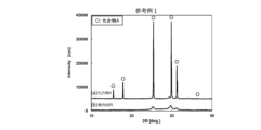
- FIG. 8 is an X-ray diffraction pattern of a composite material of compound A and a conductive material used in Reference Example 1.
- FIG. 9 is a charge/discharge curve of a battery using the positive electrode active material produced in Example 1.
- FIG. 10 is a charge/discharge curve of a battery using the positive electrode active material produced in Example 3.
- FIG. 11 is a charge/discharge curve of a battery using the positive electrode active material produced in Comparative Example 1.
- FIG. 12 is a charge/discharge curve of a battery using the positive electrode active material produced in Comparative Example 2.
- FIG. 13 is a charge/discharge curve of a battery using the positive electrode active material produced in Reference Example 1.
- FIG. 13 is a charge/discharge curve of a battery using the positive electrode active material produced in Reference Example 1.
- the present invention will be described below based on its preferred embodiments.
- the present invention relates to a method for manufacturing composite materials.
- This composite material is a composite material of a compound A and a conductive material, which will be described later.
- This composite material is particularly suitable for use as an active material for batteries.
- the production method of the present invention is roughly divided into the following steps (1) and (2).
- (1) A step of preparing compound A (hereinafter also referred to as "preparing step”).
- a step of mixing compound A and a conductive material to obtain a composite material in which both are combined hereinafter also referred to as a “mixing step”.
- mixing step each step will be described below.
- compound A is prepared.
- the compound A preferably contains a lithium (Li) element, a sulfur (S) element, and an M element.
- M elements include, for example, phosphorus (P) elements, germanium (Ge) elements, antimony (Sb) elements, silicon (Si) elements, tin (Sn) elements, aluminum (Al) elements, titanium (Ti) elements, iron (Fe ) element, nickel (Ni) element, cobalt (Co) element and manganese (Mn) element.
- the M element preferably contains at least the phosphorus (P) element, and more preferably the M element is only the P element.
- Examples of the compound containing the Li element, the S element, and the M element include Li 7 PS 6 , Li 7+3x (P 5+ 1-x Fe 2+ x )S 6 , Li, which are compounds containing only the Li element, the S element, and the M element. 7+x (P 5+ 1 ⁇ x Si 4+ x )S 6 and the like (wherein x represents a number of 0.1 or more and 1.0 or less).
- x represents a number of 0.1 or more and 1.0 or less.
- a compound containing other elements in addition to these three elements can also be used. Examples of such other elements include halogen (X) elements.
- the properties of the composite material obtained by this production method as an active material can be further enhanced.
- the X element at least one element selected from fluorine (F), chlorine (Cl), bromine (Br) and iodine (I) can be used.
- the compound containing Li element, S element, M element and X element has a composition formula (1) Li a MS b X c (wherein M is P, Ge, Sb, Si, Sn, Al, Ti, Fe , Ni, Co and Mn.X is at least one element selected from F, Cl, Br and I.) is represented by the present production method This is preferable because the properties of the resulting composite material as an active material are further improved.
- a is preferably 3.0 or more, more preferably 3.5 or more, from the viewpoint of improving lithium ion conductivity.
- a is preferably 9.0 or less, more preferably 8.0 or less.
- the atomic ratio of Li to P that is, the value of a is, for example, preferably 5.0 or more, preferably 5.5 or more, particularly 6.0 or more.
- a is, for example, preferably 8.0 or less, more preferably 7.8 or less, and particularly preferably 7.5 or less.
- b is preferably 4.0 or more, more preferably 4.5 or more, and even more preferably 5.0 or more.
- b is preferably 7.5 or less, more preferably 7.0 or less, even more preferably 6.5 or less.
- c is preferably 0.1 or more, more preferably 0.2 or more.
- c is preferably less than 1.0, more preferably 0.8 or less, even more preferably 0.6 or less.
- the M element in the composition formula (1) is preferably at least one of the P element, Ge element, Sb element, Sn element and Si element, and it is particularly preferable that the P element is contained. is preferably only the P element.
- the discharge capacity of the battery can be increased when the composite material obtained by this production method is used as the active material of the battery.
- the M element is P
- the value of c which is the atomic ratio of X to P, is preferably 0.10 or more, and more preferably 0.2 or more.
- the value of c is preferably, for example, less than 1.0, more preferably 0.8 or less, particularly preferably 0.6 or less.
- the atomic ratio of Li to P is, for example, preferably 5.0 or more, preferably 5.5 or more, and particularly preferably 6.0 or more. preferable.
- the atomic ratio of Li to P is, for example, preferably 9.0 or less, preferably 8.0 or less, and even more preferably 7.5 or less.
- the atomic ratio of Li to P may be, for example, 20.0 or less, 15.0 or less, or 9 .0 or less.
- Compound A is particularly preferably represented by the compositional formula (2) Li 7-d MS 6-d X d from the viewpoint that the composite material obtained by this production method has even higher properties as an active material.
- the value of d which is the atomic ratio of X to P
- the atomic ratio of Li to P can also be the same as in the composition formula (1) described above, so the description is omitted here.
- the compound A can be represented by Li a (M1 1-y M2 y )S b X c .
- the compound A can be represented by Li 7-d (M1 1-y M2 y )S 6-d X d .
- y is preferably 0.010 or greater, more preferably 0.020 or greater, and even more preferably 0.050 or greater.
- y is preferably 0.70 or less, more preferably 0.40 or less, and even more preferably 0.20 or less. Note that the M1 element and the M2 element can be the same as the M element described in the composition formula (1), so descriptions thereof are omitted here.
- composition of each element in compound A can be measured, for example, by ICP emission spectrometry.
- compound A preferably contains a crystal phase having an aldirodite-type crystal structure. This makes it possible to further enhance the properties of the composite material obtained by this production method as an active material.
- compound A preferably contains a crystal phase having a cubic or orthogonal aldirodite crystal structure.
- Whether or not the active material of the present invention contains a crystal phase having an aldirodite crystal structure can be determined by analyzing the active material of the present invention by an X-ray diffraction method or an X-ray total scattering method.
- a CuK ⁇ ray for example, a CuK ⁇ 1 ray can be used as a radiation source in the X-ray diffraction method.
- one or more positions selected from four at 44.40° ⁇ 1.00°, four at 47.20° ⁇ 1.00° and two at 52.00° ⁇ 1.00° It is more preferable to have a peak at 2 ⁇ 15.40° ⁇ 1 2 at .00°, 2 at 17.86° ⁇ 1.00°, 2 at 31.25° ⁇ 1.00°, 4 at 44.40° ⁇ 1.00°, 47.20° It is even more preferred to have peaks at all four positions at ⁇ 1.00° and two at 52.00° ⁇ 1.00°.
- the above-described peak positions are represented by the median value of ⁇ 1.00°, the median value of ⁇ 0.800° is preferable, and the median value of ⁇ 0.500° is more preferable.
- Compound A may contain other materials and other components as necessary. Therefore, compound A may consist of a single phase composed of a crystal phase of an aldirodite-type crystal structure, or may contain other phases in addition to the phase concerned.
- the compound A may contain a Li 2 S phase, a Li 3 PS 4 phase, a Li 4 P 2 S 6 phase, a LiCl or LiBr phase, etc. in addition to the crystal phase of the aldirodite crystal structure.
- the capacity of the composite material obtained by this production method as the active material is further increased, which is preferable.
- the compound A contains a Li element, an S element, an M element and an X element, and is mainly composed of a compound containing a crystal phase having an aldirodite type crystal structure.
- compound A may contain unavoidable impurities of less than 5% by mass, especially less than 3% by mass, to the extent that the effect of the present invention is not adversely affected.
- Compound A has the form of particles, and its particle size D1 is 0.1 ⁇ m or more, expressed as the volume cumulative particle size D50 at a cumulative volume of 50% by volume measured by a laser diffraction scattering particle size distribution measurement method. is preferred, 0.2 ⁇ m or more is more preferred, and 0.5 ⁇ m or more is even more preferred. D1 is preferably 20.0 ⁇ m or less, more preferably 10.0 ⁇ m or less, and even more preferably 5.0 ⁇ m or less.
- Compound A can be produced by a known method. For example, when compound A contains Li element, P element, S element, Cl element and Br element, lithium sulfide (Li 2 S) powder, diphosphorus pentasulfide (P 2 S 5 ) powder, and lithium chloride ( LiCl) powder and lithium bromide (LiBr) powder are mixed and fired to obtain particles of the compound.
- Li 2 S lithium sulfide
- P 2 S 5 diphosphorus pentasulfide
- LiCl lithium chloride
- LiBr lithium bromide
- the firing temperature in the case of firing in an atmosphere containing hydrogen sulfide gas is, for example, preferably 350° C. or higher, more preferably 450° C. or higher.
- the firing temperature is, for example, preferably 650° C. or lower, more preferably 600° C. or lower, and even more preferably 500° C. or lower.
- the firing temperature is preferably 350° C. or higher, for example.
- the firing temperature is, for example, preferably 550° C. or lower, more preferably 500° C. or lower, and even more preferably 450° C. or lower.
- Compound A can also be produced by amorphizing the raw material powder by a mechanical milling method, and heat-treating the amorphous raw material powder to crystallize it.
- the processing equipment and processing conditions are not particularly limited as long as the raw material powders can be sufficiently mixed and made amorphous.
- the container filled with the raw material powder rotates and revolves at high speed, so high impact energy is generated between the balls, which are the grinding media that are placed in the container together with the raw material powder, and the powder is efficiently and uniformly milled. It is possible to amorphize the raw material powder.
- the mechanical milling method may be either dry or wet.
- the processing conditions for the mechanical milling method can be appropriately set according to the processing equipment to be used, and the processing time can be, for example, 0.1 hours or more and 100 hours or less.
- the processing time can be, for example, 0.1 hours or more and 100 hours or less.
- the raw material powder can be amorphized more efficiently and uniformly.
- Balls as grinding media are preferably made of ZrO 2 , Al 2 O 3 , Si 3 N 4 (silicon nitride) or WC (tungsten carbide), and the ball diameter is preferably 0.2 mm or more and 10 mm or less.
- Compound A can be obtained by heat-treating and crystallizing the raw material powder that has been made amorphous by mechanical milling under the same firing conditions as above.
- the raw material powder subjected to the mechanical milling process is more uniformly mixed than the raw material powder obtained by ordinary pulverization and mixing, so the heat treatment temperature can be further lowered.
- Compound A can also be produced by a liquid phase method using an organic solvent. In this case, it can be obtained by dissolving a sulfide or halide as a raw material of compound A in a solvent such as tetrahydrofuran or ethanol, and precipitating compound A using the solvent as a reaction field. Compound A can also be obtained by preliminarily synthesizing compound A by another method, dissolving it in a solvent such as ethanol, and reprecipitating it. Such a liquid phase method can produce compound A in a shorter time and with less energy than other methods, and it is relatively easy to reduce the particle size of the particles.
- the particles of compound A are obtained in this way, it is preferable to adjust the particles to an appropriate particle size.
- the preferred particle size of compound A can be the same as described above, so the description is omitted here.
- the compound A and the conductive material are mixed to obtain a composite material in which the two are combined.
- a material having electronic conductivity can be used without particular limitation.
- Examples of conductive materials include various metallic materials and conductive non-metallic materials. Either one of the metallic material and the conductive non-metallic material may be used, or both may be used in combination.
- various noble metal elements such as gold (Au) element, silver (Ag) element, platinum (Pt) element, palladium (Pd) element, rhodium (Rh) element, iridium (Ir) element, ruthenium ( Ru) element and osmium (Os) element.
- various transition metal elements such as copper (Cu) element, iron (Fe) element and tin (Sn) element can be used.
- One of these metal elements may be used alone, or two or more of them may be used in combination.
- a carbon material can be used as the conductive nonmetallic material.
- Examples include graphite, acetylene black, carbon black, carbon nanofibers, carbon nanotubes, nanographenes and fullerene nanowhiskers. These carbon materials may be used singly or in combination of two or more. Among these carbon materials, when carbon black is used, the initial capacity and discharge rate characteristics of a battery using the composite material obtained by this production method as an active material can be further enhanced. From the viewpoint of making this advantage more remarkable, it is preferable to use furnace black as the carbon black, among them, it is preferable to use oil furnace black, and it is particularly preferable to use ketjen black.
- the conductive material has the form of particles, and the particle size D2 thereof is, for example, preferably 1 nm or more, more preferably 10 nm or more, and even more preferably 20 nm or more.
- D2 is, for example, preferably 500 nm or less, more preferably 300 nm or less, and even more preferably 200 nm or less.
- the particle size D2 of the conductive material is the average particle size of the Feret diameter measured by directly observing the particles using a scanning electron microscope (SEM) or a transmission electron microscope (TEM) (average of 100 or more particles value).
- the fiber diameter can be used instead of the particle size.
- the fiber diameter D3 is, for example, preferably 50 nm or more, more preferably 100 nm or more, and even more preferably 150 nm or more.
- D3 is, for example, preferably 10000 nm or less, more preferably 5000 nm or less, and even more preferably 2000 nm or less.
- the size of the conductive material is preferably smaller than the size of the compound A.
- the value of D1/D2 which is the ratio of the particle diameter D1 of the compound A to the particle diameter D2 of the conductive material, is, for example, preferably 2 or more, more preferably 5 or more, and 10 or more. is more preferable.
- the value of D1/D2 is, for example, preferably 1000 or less, more preferably 500 or less, and still more preferably 10 or more and 100 or less.
- the size of the fibrous conductive material is preferably smaller than the size of the compound A.
- the value of D1/D3, which is the ratio of the particle diameter D1 of the compound A to the fiber diameter D3 of the conductive material is, for example, preferably 1 or more, more preferably 2 or more, and 5 or more. is more preferable.
- the value of D1/D3 is, for example, preferably 1000 or less, more preferably 500 or less, and even more preferably 100 or less.
- the compound A and the conductive material are combined, for example, by applying mechanical energy to the particles of the compound A and the particles of the conductive material.
- powders are mainly stirred, mixed, kneaded, and granulated. , pulverization, dispersion, and/or surface modification.
- planetary ball mills, ball mills, jet mills, bead mills, stirring pulverizers, vibration mills, hammer mills, roller mills and atomizers can be used.
- the type of main mechanical energy that can be applied using these devices differs depending on each device. For example, when using a planetary ball mill, compressive and impact forces are mainly applied to compound A and conductive material in a mixed state.
- the centrifugal acceleration obtained during rotation of the device is not particularly limited as long as it allows the compound A and the conductive portion to be combined. More preferably. Further, the centrifugal acceleration is, for example, preferably 40 G or less, more preferably 30 G or less, and even more preferably 25 G or less. By setting the centrifugal acceleration within the above range, the discharge capacity of the battery can be further increased when the composite material obtained by the present invention is used as the active material of the battery.
- the conductive material is preferably 1 part by mass or more, more preferably 2 parts by mass or more, and 5 parts by mass or more with respect to 100 parts by mass of the compound A. More preferred.
- the conductive material is preferably, for example, 50 parts by mass or less, more preferably 20 parts by mass or less, and even more preferably 10 parts by mass or less with respect to 100 parts by mass of Compound A.
- the compound A and the conductive material are combined so that the crystallinity of the compound A is lowered.
- the properties of the composite material obtained by this production method as an active material can be further enhanced.
- the diffraction peak with the highest peak intensity is I 0 .
- the diffraction peak with the highest peak intensity is Let It be.
- the crystallinity of the composite material decreases, the half width of each diffraction peak in the X-ray diffraction pattern widens, so that multiple diffraction peaks may overlap.
- the diffraction peaks are regarded as one diffraction peak and designated as It .
- the mixing step of the compound A and the conductive material is preferably performed so that the above-mentioned degree of amorphousness N is, for example, 97% or more, especially 98% or more, and further preferably 99% or more. preferable.
- the degree of amorphousness N is within the above range, the discharge capacity of a battery using the composite material obtained by the present invention as an active material can be increased.
- the impact force is preferably 0.50 N or more, particularly 0.70 N or more, and particularly preferably 0.90 N or more.
- the impact force is a force generated when an object with mass collides with the impact force, and is expressed by the following formula (2).
- Impact force (F) m x G (2)
- m is the weight (kg) of the colliding object and G is the acceleration (m/s 2 ).
- m and G is the centrifugal acceleration.
- conditions for mixing compound A and a conductive material using a planetary ball mill include a method of adjusting the revolution and/or rotation speed of the device, the diameter, material and number of balls, and the mixing time.
- lithium sulfide Li 2 S
- Lithium sulfide functions as a positive electrode active material of a battery and has the effect of increasing the discharge capacity of the battery. Therefore, it is desirable that lithium sulfide is produced as a result of the compositing.
- the compound A and the conductive material are combined so that the compound A is amorphous in the mixing step, it is not particularly limited whether the conductive material is amorphous.
- the composite material thus obtained comprises a main portion containing particles of Compound A and a conductive portion containing a conductive material dispersed on the surface and/or inside of the main portion and imparting electronic conductivity.
- the particles are composed.
- the conductive portion plays a role of an electron conduction path when lithium is desorbed from the main portion, it is desirable that the conductive portion is uniformly dispersed and closely attached to the surface and inside.
- the aldirodite production ratio of the composite material obtained by this production method is not particularly limited as long as the effects of the present invention are achieved.
- the aldirodite formation ratio is, for example, preferably 40 or less, more preferably 30 or less, particularly preferably 10 or less, further preferably 5 or less, and most preferably 0. Note that the aldirodite production ratio can be the same as that described in the section of Examples described later, so description thereof is omitted here.
- the compound A and the conductive material are "composited", which means that the conductive portion is in a state in which the conductive portion is in close contact with the main portion and dispersed on the surface or inside the main portion. is preferred.
- Examples of “complexed” aspects include aspects in which the particles of the conductive material are inseparably dispersed on the surface and/or inside of the particles of compound A, and particles of compound A that constitute the main portion and the conductive portion.
- An embodiment in which particles of the constituting conductive material are chemically reacted and bonded is exemplified.
- the composite material obtained by this production method is subjected to an energy dispersive X-ray spectrometer.
- SEM-EDS scanning electron microscope
- mapping the constituent elements (for example, sulfur element) of compound A that constitutes the main part and the constituent elements of the conductive material that constitutes the conductive part the main It refers to a state in which the constituent elements of the compound A constituting the part and the constituent elements of the conductive material constituting the conductive part are present so as to overlap each other.
- the constituent elements of compound A constituting the main part and the conductive part It is a state in which the constituent elements of the conductive material that constitute the are present so as to overlap.
- the fact that the main portion and the conductive portion are chemically reacted and combined can be confirmed by the presence or absence of a C—S bond by Raman spectroscopy or photoelectron spectroscopy, for example, when the conductive material is a carbon material.
- the composite material obtained by this production method When the composite material obtained by this production method is used as an active material, in the active material, electrons are smoothly transferred between the outside of the active material and the main part through the conductive part. As a result, it acquires electrical conductivity and acquires the desorption function of lithium ions. Furthermore, a battery having a composite material obtained by this production method as an active material by mainly using compound A having an aldirodite crystal structure with a high lithium ion conductivity and high lithium ion conductivity, A high discharge capacity is expressed. In particular, the composite material obtained by this production method is useful as a positive electrode active material for lithium ion batteries.
- the active material When using the composite material obtained by this production method as an active material, the active material can be mixed with an electrolyte, a conductive material, a binder, and the like to form an electrode mixture.
- An electrode mixture using the composite material obtained by this manufacturing method as a positive electrode active material is a positive electrode mixture that constitutes the positive electrode layer.
- the electrolyte can be, for example, a solid electrolyte.
- the solid electrolyte preferably has ionic conductivity such as lithium ion conductivity.
- Specific examples include inorganic solid electrolytes such as sulfide solid electrolytes, oxide solid electrolytes, nitride solid electrolytes and halide solid electrolytes, and organic polymer electrolytes such as polymer electrolytes.
- the solid electrolyte is preferably a sulfide solid electrolyte from the viewpoint of making the effects of the present invention more remarkable.
- the sulfide solid electrolyte may be the same as sulfide solid electrolytes used in general solid batteries.
- the sulfide solid electrolyte may contain, for example, Li and S and have lithium ion conductivity.
- the sulfide solid electrolyte may be any of crystalline material, glass ceramics, and glass.
- the sulfide solid electrolyte may have an aldirodite crystal structure. Examples of such sulfide solid electrolytes include Li 2 SP 2 S 5 , Li 2 SP 2 S 5 -LiX ("X" represents one or more halogen elements), Li 2 S- P2S5 - P2O5 , Li2S - Li3PO4 - P2S5 , Li3PS4 , Li4P2S6 , Li10GeP2S12 , Li3.25Ge0 .
- X represents one or more halogen elements, a is 3.0 represents a number of 9.0 or less, b represents a number of 3.5 or more and 6.0 or less, and c represents a number of 0.1 or more and 3.0 or less.
- sulfide solid electrolytes described in International Publication No. 2013/099834 and International Publication No. 2015/001818 are included.
- the active material contained in the electrode mixture may be only the composite material obtained by this production method, or the composite material may be used in combination with other active materials.
- Other active materials include known active materials containing elemental sulfur and sulfur.
- the proportion of the composite material in the electrode mixture may be, for example, 20% by mass or more, 30% by mass or more, or 40% by mass or more. On the other hand, the ratio may be, for example, 70% by mass or less, or 60% by mass or less.
- a battery containing the composite material obtained by the present production method as an active material includes a positive electrode layer containing a positive electrode active material, a negative electrode layer containing a negative electrode active material, and a solid electrolyte layer containing a solid electrolyte, wherein the positive electrode active material is It is preferably a composite material obtained by this manufacturing method.
- a battery can be produced, for example, by stacking three layers of the positive electrode layer, the solid electrolyte layer, and the negative electrode layer produced as described above, and molding them under pressure.
- a battery having the composite material obtained by this production method as an active material is preferably a lithium-ion battery, and more preferably a lithium-sulfur battery. Batteries here include solid batteries having a solid electrolyte layer, in particular all-solid-state batteries.
- a battery having the composite material obtained by the present production method as an active material may be a primary battery or a secondary battery, but is preferably used for a secondary battery. is particularly preferred.
- the term “lithium secondary battery” broadly includes secondary batteries that charge and discharge by moving lithium ions between a positive electrode and a negative electrode.
- a solid battery has a positive electrode layer, a negative electrode layer, and a solid electrolyte layer between the positive electrode layer and the negative electrode layer.
- the active material of the present invention is preferably contained in the positive electrode layer.
- Solid battery means a solid battery that does not contain any liquid or gel substance as an electrolyte, and also includes, for example, 50% by mass or less, 30% by mass or less, or 10% by mass or less of liquid or gel substance as an electrolyte. Aspects are also included.
- the present invention further discloses the following method for manufacturing a composite material.
- Lithium (Li) element, sulfur (S) element, and M element M is phosphorus (P) element, germanium (Ge) element, antimony (Sb) element, silicon (Si) element, tin (Sn) element, aluminum (Al) element, titanium (Ti) element, iron (Fe) element, nickel (Ni) element, cobalt (Co) element and manganese (Mn) element.
- Example 1 (1) Preparation Step A compound A and a conductive material having compositions shown in Table 1 below were prepared. (2) Mixing step Compound A and the conductive material were mixed in the amounts shown in Table 1. A planetary ball mill (manufactured by Fritsch, P-7) was used for mixing. The balls used were made of zirconia and had a diameter of 5 mm. Mixing was performed for 10 hours at a rotation speed of 500 rpm. The impact force applied at this time was as shown in Table 1. Thus, a composite material in which the compound A and the conductive material were combined was obtained.
- a planetary ball mill manufactured by Fritsch, P-7
- the resulting composite material was pulverized in a mortar and sieved with a sieve having an opening of 53 ⁇ m to obtain particles having a particle diameter D50 of 6.6 ⁇ m. All of the above operations were carried out in a glove box replaced with sufficiently dried Ar gas (dew point of ⁇ 60° C. or lower).
- Example 2 As the compound A and the conductive material, those shown in Table 1 were used. A composite material was obtained in the same manner as in Example 1 except for the above.
- the "X/P atomic number ratio" shown in Table 1 represents the ratio of the atomic number of the X (halogen) element to the atomic number of the phosphorus element.
- the “Li/P atomic ratio” represents the ratio of the number of atoms of the Li element to the number of atoms of the phosphorus element.
- Example 3 As the compound A, those shown in Table 1 were used. A composite material was obtained in the same manner as in Example 1 except for the above.
- Example 5 As the compound A, those shown in Table 1 were used. Further, using zirconia balls having a diameter of 10 mm, mixing was performed by a planetary ball mill at a rotational speed of 600 rpm for 10 hours. The impact force applied at this time was as shown in Table 1. A composite material was obtained in the same manner as in Example 1 except for these.
- Example 1 As the compound A, those shown in Table 1 were used. Further, using zirconia balls having a diameter of 10 mm, mixing was performed by a planetary ball mill at a rotational speed of 600 rpm for 10 hours. The impact force applied at this time was as shown in Table 1. A composite material was obtained in the same manner as in Example 1 except for these.
- Example 2 As the compound A and the conductive material, those shown in Table 1 were used. Further, mixing by a planetary ball mill was performed for 1 hour at a rotation speed of 300 rpm. The impact force applied at this time was as shown in Table 1. A composite material was obtained in the same manner as in Example 1 except for these.
- the aldirodite formation ratio of the composite materials produced in Examples, Comparative Examples and Reference Examples was measured by the following method. Table 1 shows the results.
- [Aldirodite formation ratio] In the X-ray diffraction pattern of the composite material, when compound A has a cubic aldirodite crystal structure, the intensity of the diffraction peak observed at 29.62 ° ⁇ 1.00 ° is Ia , and the cubic aldirodite crystal structure is , the intensity of the diffraction peak observed at 29.77° ⁇ 1.00° is Ia .
- a composite material can be evaluated by the aldirodite production ratio represented by the following equation (3).
- Aldirodite formation ratio (%) 100 x I a / (I a + I b ) (3)
- impurity phases other than compound A and lithium sulfide may be confirmed, but since the production ratio is small, the production ratio of the impurity phase does not need to be considered in the aldirodite production ratio. .
- solid battery cells were produced using the composite materials produced in Examples, Comparative Examples, and Reference Examples as positive electrode active materials, and the initial discharge capacity was measured by the following method. Table 1 shows the results.
- An all-solid battery cell in which a positive electrode layer, a solid electrolyte layer and a negative electrode layer are laminated was produced by sandwiching with a load of .
- the thickness of each layer is approximately 40 ⁇ m for the positive electrode layer, approximately 600 ⁇ m for the solid electrolyte layer, and approximately 400 ⁇ m for the negative electrode layer.
- the production of all-solid-state battery cells was carried out in a glove box that was replaced with argon gas having a dew point temperature of -60°C.
- the produced all-solid-state battery was connected to a charge/discharge measuring device in an environmental tester maintained at 25° C., and battery characteristics were evaluated. A current of 2.0 mA during charging and discharging was defined as a 1C rate.
- a method is provided that can suitably produce a material that can improve the performance of a lithium ion battery.
Landscapes
- Chemical & Material Sciences (AREA)
- Chemical Kinetics & Catalysis (AREA)
- Electrochemistry (AREA)
- General Chemical & Material Sciences (AREA)
- Inorganic Chemistry (AREA)
- Organic Chemistry (AREA)
- Composite Materials (AREA)
- Engineering & Computer Science (AREA)
- Manufacturing & Machinery (AREA)
- Crystallography & Structural Chemistry (AREA)
- Materials Engineering (AREA)
- Battery Electrode And Active Subsutance (AREA)
- Glass Compositions (AREA)
Priority Applications (6)
| Application Number | Priority Date | Filing Date | Title |
|---|---|---|---|
| EP23760070.5A EP4485577A4 (en) | 2022-02-26 | 2023-02-22 | COMPOSITE MATERIAL AND METHOD FOR PRODUCING SAME |
| JP2023545812A JP7442022B2 (ja) | 2022-02-26 | 2023-02-22 | 複合材料及びその製造方法 |
| KR1020247002763A KR102729144B1 (ko) | 2022-02-26 | 2023-02-22 | 복합 재료 및 그 제조 방법 |
| US18/291,464 US12424626B2 (en) | 2022-02-26 | 2023-02-22 | Composite material, and method for manufacturing same |
| CN202380013079.9A CN117836982B (zh) | 2022-02-26 | 2023-02-22 | 复合材料及其制造方法 |
| JP2024022635A JP7505135B2 (ja) | 2022-02-26 | 2024-02-19 | 複合材料及びその製造方法 |
Applications Claiming Priority (2)
| Application Number | Priority Date | Filing Date | Title |
|---|---|---|---|
| JP2022028735 | 2022-02-26 | ||
| JP2022-028735 | 2022-02-26 |
Publications (1)
| Publication Number | Publication Date |
|---|---|
| WO2023163071A1 true WO2023163071A1 (ja) | 2023-08-31 |
Family
ID=87766048
Family Applications (1)
| Application Number | Title | Priority Date | Filing Date |
|---|---|---|---|
| PCT/JP2023/006584 Ceased WO2023163071A1 (ja) | 2022-02-26 | 2023-02-22 | 複合材料及びその製造方法 |
Country Status (6)
| Country | Link |
|---|---|
| US (1) | US12424626B2 (https=) |
| EP (1) | EP4485577A4 (https=) |
| JP (2) | JP7442022B2 (https=) |
| KR (1) | KR102729144B1 (https=) |
| CN (1) | CN117836982B (https=) |
| WO (1) | WO2023163071A1 (https=) |
Cited By (2)
| Publication number | Priority date | Publication date | Assignee | Title |
|---|---|---|---|---|
| WO2024166908A1 (ja) * | 2023-02-07 | 2024-08-15 | 三井金属鉱業株式会社 | 活物質、固体電解質、電極合剤並びに電池 |
| WO2025206032A1 (ja) * | 2024-03-29 | 2025-10-02 | 三井金属鉱業株式会社 | 活物質、電極合剤並びに電池 |
Citations (6)
| Publication number | Priority date | Publication date | Assignee | Title |
|---|---|---|---|---|
| WO2013099834A1 (ja) | 2011-12-28 | 2013-07-04 | 三井金属鉱業株式会社 | 硫化物系固体電解質 |
| WO2015001818A1 (ja) | 2013-07-04 | 2015-01-08 | 三井金属鉱業株式会社 | 結晶性固体電解質及びその製造方法 |
| CN109256555A (zh) | 2018-10-16 | 2019-01-22 | 清华大学 | 一种硫系复合正极材料及其全固态锂电池以及它们的制备方法 |
| CN111082128A (zh) * | 2019-12-23 | 2020-04-28 | 中国科学院青岛生物能源与过程研究所 | 一种高功率全固态电池及其制备 |
| JP2020135947A (ja) * | 2019-02-13 | 2020-08-31 | トヨタ自動車株式会社 | 炭素コーティング固体電解質粒子の製造方法 |
| WO2022045302A1 (ja) * | 2020-08-28 | 2022-03-03 | 三井金属鉱業株式会社 | 活物質及びその製造方法、電極合剤並びに電池 |
Family Cites Families (4)
| Publication number | Priority date | Publication date | Assignee | Title |
|---|---|---|---|---|
| JP6352960B2 (ja) * | 2016-02-09 | 2018-07-04 | 国立大学法人東京工業大学 | 硫化物固体電解質材料、電池および硫化物固体電解質材料の製造方法 |
| KR102507008B1 (ko) * | 2017-12-20 | 2023-03-06 | 현대자동차주식회사 | 단일 원소로부터 유래된 아지로다이트형 결정구조를 갖는 전고체 전지용 황화물계 고체전해질 및 이의 제조방법 |
| WO2020214786A1 (en) * | 2019-04-17 | 2020-10-22 | University Of Louisville Research Foundation, Inc. | Method for wet chemical synthesis of lithium argyrodites |
| TWI896584B (zh) * | 2019-12-27 | 2025-09-11 | 日商三井金屬鑛業股份有限公司 | 硫化物固體電解質及其製造方法 |
-
2023
- 2023-02-22 WO PCT/JP2023/006584 patent/WO2023163071A1/ja not_active Ceased
- 2023-02-22 KR KR1020247002763A patent/KR102729144B1/ko active Active
- 2023-02-22 US US18/291,464 patent/US12424626B2/en active Active
- 2023-02-22 CN CN202380013079.9A patent/CN117836982B/zh active Active
- 2023-02-22 JP JP2023545812A patent/JP7442022B2/ja active Active
- 2023-02-22 EP EP23760070.5A patent/EP4485577A4/en active Pending
-
2024
- 2024-02-19 JP JP2024022635A patent/JP7505135B2/ja active Active
Patent Citations (6)
| Publication number | Priority date | Publication date | Assignee | Title |
|---|---|---|---|---|
| WO2013099834A1 (ja) | 2011-12-28 | 2013-07-04 | 三井金属鉱業株式会社 | 硫化物系固体電解質 |
| WO2015001818A1 (ja) | 2013-07-04 | 2015-01-08 | 三井金属鉱業株式会社 | 結晶性固体電解質及びその製造方法 |
| CN109256555A (zh) | 2018-10-16 | 2019-01-22 | 清华大学 | 一种硫系复合正极材料及其全固态锂电池以及它们的制备方法 |
| JP2020135947A (ja) * | 2019-02-13 | 2020-08-31 | トヨタ自動車株式会社 | 炭素コーティング固体電解質粒子の製造方法 |
| CN111082128A (zh) * | 2019-12-23 | 2020-04-28 | 中国科学院青岛生物能源与过程研究所 | 一种高功率全固态电池及其制备 |
| WO2022045302A1 (ja) * | 2020-08-28 | 2022-03-03 | 三井金属鉱業株式会社 | 活物質及びその製造方法、電極合剤並びに電池 |
Non-Patent Citations (2)
| Title |
|---|
| JOURNAL OF POWER SOURCES, vol. 293, 2015, pages 721 - 725 |
| See also references of EP4485577A4 |
Cited By (2)
| Publication number | Priority date | Publication date | Assignee | Title |
|---|---|---|---|---|
| WO2024166908A1 (ja) * | 2023-02-07 | 2024-08-15 | 三井金属鉱業株式会社 | 活物質、固体電解質、電極合剤並びに電池 |
| WO2025206032A1 (ja) * | 2024-03-29 | 2025-10-02 | 三井金属鉱業株式会社 | 活物質、電極合剤並びに電池 |
Also Published As
| Publication number | Publication date |
|---|---|
| JP7505135B2 (ja) | 2024-06-24 |
| JP2024059733A (ja) | 2024-05-01 |
| EP4485577A1 (en) | 2025-01-01 |
| KR20240024258A (ko) | 2024-02-23 |
| US20250105285A1 (en) | 2025-03-27 |
| JP7442022B2 (ja) | 2024-03-01 |
| CN117836982B (zh) | 2025-05-13 |
| US12424626B2 (en) | 2025-09-23 |
| KR102729144B1 (ko) | 2024-11-13 |
| JPWO2023163071A1 (https=) | 2023-08-31 |
| CN117836982A (zh) | 2024-04-05 |
| EP4485577A4 (en) | 2025-04-23 |
Similar Documents
| Publication | Publication Date | Title |
|---|---|---|
| CN116057009B (zh) | 活性物质及其制造方法、电极合剂以及电池 | |
| JP7344345B2 (ja) | 硫化物系無機固体電解質材料の製造方法 | |
| JP7505135B2 (ja) | 複合材料及びその製造方法 | |
| KR20190016904A (ko) | 정극합재 및 그 제조방법 | |
| JP5895917B2 (ja) | 硫化物固体電解質材料、電池および硫化物固体電解質材料の製造方法 | |
| US11075375B2 (en) | Cathode mixture, all solid state battery, method for producing cathode mixture, and method for producing all solid state battery | |
| JP2020173992A (ja) | 硫化物固体電解質、硫化物固体電解質の製造方法、電極体および全固体電池 | |
| JP7192726B2 (ja) | 負極材料及びその製造方法 | |
| WO2024166908A1 (ja) | 活物質、固体電解質、電極合剤並びに電池 | |
| WO2024048476A1 (ja) | 複合材料の製造方法及び複合材料 | |
| JP7421011B2 (ja) | 電池 | |
| WO2025206032A1 (ja) | 活物質、電極合剤並びに電池 | |
| JP2014214037A (ja) | 多硫化チタン−炭素複合体 | |
| WO2024166792A1 (ja) | 負極合剤、スラリー、負極及び電池 | |
| WO2024185669A1 (ja) | 正極合材の製造方法、正極合材及びリチウムイオン電池 | |
| EP4664548A1 (en) | Negative electrode and battery using same |
Legal Events
| Date | Code | Title | Description |
|---|---|---|---|
| WWE | Wipo information: entry into national phase |
Ref document number: 2023545812 Country of ref document: JP |
|
| 121 | Ep: the epo has been informed by wipo that ep was designated in this application |
Ref document number: 23760070 Country of ref document: EP Kind code of ref document: A1 |
|
| WWE | Wipo information: entry into national phase |
Ref document number: 18291464 Country of ref document: US |
|
| ENP | Entry into the national phase |
Ref document number: 20247002763 Country of ref document: KR Kind code of ref document: A |
|
| WWE | Wipo information: entry into national phase |
Ref document number: 1020247002763 Country of ref document: KR |
|
| WWE | Wipo information: entry into national phase |
Ref document number: 202380013079.9 Country of ref document: CN |
|
| WWE | Wipo information: entry into national phase |
Ref document number: 2023760070 Country of ref document: EP |
|
| NENP | Non-entry into the national phase |
Ref country code: DE |
|
| ENP | Entry into the national phase |
Ref document number: 2023760070 Country of ref document: EP Effective date: 20240926 |
|
| WWP | Wipo information: published in national office |
Ref document number: 18291464 Country of ref document: US |
|
| WWG | Wipo information: grant in national office |
Ref document number: 202380013079.9 Country of ref document: CN |
|
| WWG | Wipo information: grant in national office |
Ref document number: 18291464 Country of ref document: US |