WO2023163009A1 - Matériau de matelas, dispositif de purification de gaz d'échappement et procédé de production de matériau de matelas - Google Patents
Matériau de matelas, dispositif de purification de gaz d'échappement et procédé de production de matériau de matelas Download PDFInfo
- Publication number
- WO2023163009A1 WO2023163009A1 PCT/JP2023/006349 JP2023006349W WO2023163009A1 WO 2023163009 A1 WO2023163009 A1 WO 2023163009A1 JP 2023006349 W JP2023006349 W JP 2023006349W WO 2023163009 A1 WO2023163009 A1 WO 2023163009A1
- Authority
- WO
- WIPO (PCT)
- Prior art keywords
- inorganic
- binder
- mat
- organic binder
- mat material
- Prior art date
Links
- 239000000463 material Substances 0.000 title claims abstract description 193
- 238000004519 manufacturing process Methods 0.000 title claims description 22
- 238000000746 purification Methods 0.000 title description 3
- 239000011230 binding agent Substances 0.000 claims abstract description 361
- 239000012784 inorganic fiber Substances 0.000 claims abstract description 148
- 239000000203 mixture Substances 0.000 claims description 75
- 238000000034 method Methods 0.000 claims description 55
- 239000011247 coating layer Substances 0.000 claims description 42
- 239000000835 fiber Substances 0.000 claims description 38
- 238000002360 preparation method Methods 0.000 claims description 26
- 239000002002 slurry Substances 0.000 claims description 22
- 239000002270 dispersing agent Substances 0.000 claims description 21
- 230000001681 protective effect Effects 0.000 claims description 21
- 239000007788 liquid Substances 0.000 claims description 19
- 229910052751 metal Inorganic materials 0.000 claims description 15
- 239000002184 metal Substances 0.000 claims description 15
- 238000001035 drying Methods 0.000 claims description 13
- 239000002904 solvent Substances 0.000 claims description 9
- 239000006185 dispersion Substances 0.000 claims description 8
- 238000002156 mixing Methods 0.000 claims description 6
- 238000004220 aggregation Methods 0.000 claims description 4
- 230000002776 aggregation Effects 0.000 claims description 4
- 239000002612 dispersion medium Substances 0.000 claims description 4
- 230000004931 aggregating effect Effects 0.000 claims description 3
- 239000010410 layer Substances 0.000 claims description 2
- 238000012360 testing method Methods 0.000 description 35
- 238000004080 punching Methods 0.000 description 16
- 239000007787 solid Substances 0.000 description 14
- 238000009987 spinning Methods 0.000 description 14
- 230000000052 comparative effect Effects 0.000 description 12
- VYPSYNLAJGMNEJ-UHFFFAOYSA-N Silicium dioxide Chemical compound O=[Si]=O VYPSYNLAJGMNEJ-UHFFFAOYSA-N 0.000 description 9
- 238000007906 compression Methods 0.000 description 8
- 238000001000 micrograph Methods 0.000 description 8
- 239000003960 organic solvent Substances 0.000 description 8
- 230000008569 process Effects 0.000 description 8
- PNEYBMLMFCGWSK-UHFFFAOYSA-N aluminium oxide Inorganic materials [O-2].[O-2].[O-2].[Al+3].[Al+3] PNEYBMLMFCGWSK-UHFFFAOYSA-N 0.000 description 7
- 210000004027 cell Anatomy 0.000 description 7
- 230000006835 compression Effects 0.000 description 7
- 239000012701 inorganic fiber precursor Substances 0.000 description 7
- 238000010586 diagram Methods 0.000 description 6
- 238000010304 firing Methods 0.000 description 6
- 239000011259 mixed solution Substances 0.000 description 6
- 239000000377 silicon dioxide Substances 0.000 description 6
- 229910001220 stainless steel Inorganic materials 0.000 description 6
- 239000010935 stainless steel Substances 0.000 description 6
- 150000003839 salts Chemical class 0.000 description 5
- WYURNTSHIVDZCO-UHFFFAOYSA-N Tetrahydrofuran Chemical compound C1CCOC1 WYURNTSHIVDZCO-UHFFFAOYSA-N 0.000 description 4
- VSCWAEJMTAWNJL-UHFFFAOYSA-K aluminium trichloride Chemical compound Cl[Al](Cl)Cl VSCWAEJMTAWNJL-UHFFFAOYSA-K 0.000 description 4
- 125000000129 anionic group Chemical group 0.000 description 4
- 210000002421 cell wall Anatomy 0.000 description 4
- 230000000694 effects Effects 0.000 description 4
- 229920000620 organic polymer Polymers 0.000 description 4
- 239000005022 packaging material Substances 0.000 description 4
- 239000002245 particle Substances 0.000 description 4
- 229920005989 resin Polymers 0.000 description 4
- 239000011347 resin Substances 0.000 description 4
- 239000003566 sealing material Substances 0.000 description 4
- 239000000126 substance Substances 0.000 description 4
- 229910018072 Al 2 O 3 Inorganic materials 0.000 description 3
- 239000004372 Polyvinyl alcohol Substances 0.000 description 3
- 229910004298 SiO 2 Inorganic materials 0.000 description 3
- 239000002585 base Substances 0.000 description 3
- 239000011248 coating agent Substances 0.000 description 3
- 238000000576 coating method Methods 0.000 description 3
- 238000002485 combustion reaction Methods 0.000 description 3
- 238000005520 cutting process Methods 0.000 description 3
- 230000007423 decrease Effects 0.000 description 3
- 238000005470 impregnation Methods 0.000 description 3
- 239000004745 nonwoven fabric Substances 0.000 description 3
- 229920000642 polymer Polymers 0.000 description 3
- 229920002451 polyvinyl alcohol Polymers 0.000 description 3
- RMAQACBXLXPBSY-UHFFFAOYSA-N silicic acid Chemical compound O[Si](O)(O)O RMAQACBXLXPBSY-UHFFFAOYSA-N 0.000 description 3
- 238000004804 winding Methods 0.000 description 3
- NIXOWILDQLNWCW-UHFFFAOYSA-M Acrylate Chemical compound [O-]C(=O)C=C NIXOWILDQLNWCW-UHFFFAOYSA-M 0.000 description 2
- 229920002134 Carboxymethyl cellulose Polymers 0.000 description 2
- WSFSSNUMVMOOMR-UHFFFAOYSA-N Formaldehyde Chemical compound O=C WSFSSNUMVMOOMR-UHFFFAOYSA-N 0.000 description 2
- CPLXHLVBOLITMK-UHFFFAOYSA-N Magnesium oxide Chemical compound [Mg]=O CPLXHLVBOLITMK-UHFFFAOYSA-N 0.000 description 2
- PPBRXRYQALVLMV-UHFFFAOYSA-N Styrene Chemical compound C=CC1=CC=CC=C1 PPBRXRYQALVLMV-UHFFFAOYSA-N 0.000 description 2
- MCMNRKCIXSYSNV-UHFFFAOYSA-N Zirconium dioxide Chemical compound O=[Zr]=O MCMNRKCIXSYSNV-UHFFFAOYSA-N 0.000 description 2
- 239000002253 acid Substances 0.000 description 2
- 239000007864 aqueous solution Substances 0.000 description 2
- 230000015572 biosynthetic process Effects 0.000 description 2
- 238000007664 blowing Methods 0.000 description 2
- 239000001768 carboxy methyl cellulose Substances 0.000 description 2
- 235000010948 carboxy methyl cellulose Nutrition 0.000 description 2
- 239000008112 carboxymethyl-cellulose Substances 0.000 description 2
- 238000007766 curtain coating Methods 0.000 description 2
- KZHJGOXRZJKJNY-UHFFFAOYSA-N dioxosilane;oxo(oxoalumanyloxy)alumane Chemical compound O=[Si]=O.O=[Si]=O.O=[Al]O[Al]=O.O=[Al]O[Al]=O.O=[Al]O[Al]=O KZHJGOXRZJKJNY-UHFFFAOYSA-N 0.000 description 2
- 230000001747 exhibiting effect Effects 0.000 description 2
- 239000008394 flocculating agent Substances 0.000 description 2
- 238000010438 heat treatment Methods 0.000 description 2
- 150000002484 inorganic compounds Chemical class 0.000 description 2
- 229910010272 inorganic material Inorganic materials 0.000 description 2
- 229920000126 latex Polymers 0.000 description 2
- 229910052863 mullite Inorganic materials 0.000 description 2
- YLQBMQCUIZJEEH-UHFFFAOYSA-N tetrahydrofuran Natural products C=1C=COC=1 YLQBMQCUIZJEEH-UHFFFAOYSA-N 0.000 description 2
- XLYOFNOQVPJJNP-UHFFFAOYSA-N water Substances O XLYOFNOQVPJJNP-UHFFFAOYSA-N 0.000 description 2
- 230000037303 wrinkles Effects 0.000 description 2
- 229920000178 Acrylic resin Polymers 0.000 description 1
- 239000004925 Acrylic resin Substances 0.000 description 1
- ODINCKMPIJJUCX-UHFFFAOYSA-N Calcium oxide Chemical compound [Ca]=O ODINCKMPIJJUCX-UHFFFAOYSA-N 0.000 description 1
- 108010010803 Gelatin Proteins 0.000 description 1
- 229920002845 Poly(methacrylic acid) Polymers 0.000 description 1
- 239000002202 Polyethylene glycol Substances 0.000 description 1
- 239000004743 Polypropylene Substances 0.000 description 1
- 229920002125 Sokalan® Polymers 0.000 description 1
- 229920002472 Starch Polymers 0.000 description 1
- 150000007513 acids Chemical class 0.000 description 1
- 239000000654 additive Substances 0.000 description 1
- 239000000292 calcium oxide Substances 0.000 description 1
- 235000012255 calcium oxide Nutrition 0.000 description 1
- 239000005018 casein Substances 0.000 description 1
- BECPQYXYKAMYBN-UHFFFAOYSA-N casein, tech. Chemical compound NCCCCC(C(O)=O)N=C(O)C(CC(O)=O)N=C(O)C(CCC(O)=N)N=C(O)C(CC(C)C)N=C(O)C(CCC(O)=O)N=C(O)C(CC(O)=O)N=C(O)C(CCC(O)=O)N=C(O)C(C(C)O)N=C(O)C(CCC(O)=N)N=C(O)C(CCC(O)=N)N=C(O)C(CCC(O)=N)N=C(O)C(CCC(O)=O)N=C(O)C(CCC(O)=O)N=C(O)C(COP(O)(O)=O)N=C(O)C(CCC(O)=N)N=C(O)C(N)CC1=CC=CC=C1 BECPQYXYKAMYBN-UHFFFAOYSA-N 0.000 description 1
- 235000021240 caseins Nutrition 0.000 description 1
- 239000003054 catalyst Substances 0.000 description 1
- 239000000919 ceramic Substances 0.000 description 1
- 230000008859 change Effects 0.000 description 1
- 239000003795 chemical substances by application Substances 0.000 description 1
- 229910052878 cordierite Inorganic materials 0.000 description 1
- 230000018044 dehydration Effects 0.000 description 1
- 238000006297 dehydration reaction Methods 0.000 description 1
- 230000006866 deterioration Effects 0.000 description 1
- JSKIRARMQDRGJZ-UHFFFAOYSA-N dimagnesium dioxido-bis[(1-oxido-3-oxo-2,4,6,8,9-pentaoxa-1,3-disila-5,7-dialuminabicyclo[3.3.1]nonan-7-yl)oxy]silane Chemical compound [Mg++].[Mg++].[O-][Si]([O-])(O[Al]1O[Al]2O[Si](=O)O[Si]([O-])(O1)O2)O[Al]1O[Al]2O[Si](=O)O[Si]([O-])(O1)O2 JSKIRARMQDRGJZ-UHFFFAOYSA-N 0.000 description 1
- 238000007599 discharging Methods 0.000 description 1
- 238000006073 displacement reaction Methods 0.000 description 1
- 238000000921 elemental analysis Methods 0.000 description 1
- 239000003822 epoxy resin Substances 0.000 description 1
- 238000011156 evaluation Methods 0.000 description 1
- 210000003746 feather Anatomy 0.000 description 1
- 238000001914 filtration Methods 0.000 description 1
- 229920000159 gelatin Polymers 0.000 description 1
- 239000008273 gelatin Substances 0.000 description 1
- 235000019322 gelatine Nutrition 0.000 description 1
- 235000011852 gelatine desserts Nutrition 0.000 description 1
- 239000003365 glass fiber Substances 0.000 description 1
- LNEPOXFFQSENCJ-UHFFFAOYSA-N haloperidol Chemical compound C1CC(O)(C=2C=CC(Cl)=CC=2)CCN1CCCC(=O)C1=CC=C(F)C=C1 LNEPOXFFQSENCJ-UHFFFAOYSA-N 0.000 description 1
- 230000036541 health Effects 0.000 description 1
- 239000012943 hotmelt Substances 0.000 description 1
- 239000010954 inorganic particle Substances 0.000 description 1
- 239000004816 latex Substances 0.000 description 1
- 239000000395 magnesium oxide Substances 0.000 description 1
- 238000005259 measurement Methods 0.000 description 1
- 230000007246 mechanism Effects 0.000 description 1
- 238000002844 melting Methods 0.000 description 1
- 230000008018 melting Effects 0.000 description 1
- 238000000465 moulding Methods 0.000 description 1
- PSZYNBSKGUBXEH-UHFFFAOYSA-M naphthalene-1-sulfonate Chemical compound C1=CC=C2C(S(=O)(=O)[O-])=CC=CC2=C1 PSZYNBSKGUBXEH-UHFFFAOYSA-M 0.000 description 1
- 239000013618 particulate matter Substances 0.000 description 1
- 239000004584 polyacrylic acid Substances 0.000 description 1
- 229920000647 polyepoxide Polymers 0.000 description 1
- 229920001223 polyethylene glycol Polymers 0.000 description 1
- -1 polypropylene Polymers 0.000 description 1
- 229920001155 polypropylene Polymers 0.000 description 1
- 229920000036 polyvinylpyrrolidone Polymers 0.000 description 1
- 239000001267 polyvinylpyrrolidone Substances 0.000 description 1
- 235000013855 polyvinylpyrrolidone Nutrition 0.000 description 1
- 239000000843 powder Substances 0.000 description 1
- 239000002994 raw material Substances 0.000 description 1
- 230000009467 reduction Effects 0.000 description 1
- 238000000550 scanning electron microscopy energy dispersive X-ray spectroscopy Methods 0.000 description 1
- 238000007789 sealing Methods 0.000 description 1
- HBMJWWWQQXIZIP-UHFFFAOYSA-N silicon carbide Chemical compound [Si+]#[C-] HBMJWWWQQXIZIP-UHFFFAOYSA-N 0.000 description 1
- 229910010271 silicon carbide Inorganic materials 0.000 description 1
- 239000008107 starch Substances 0.000 description 1
- 235000019698 starch Nutrition 0.000 description 1
- 238000003756 stirring Methods 0.000 description 1
- 150000003457 sulfones Chemical class 0.000 description 1
- 229920005992 thermoplastic resin Polymers 0.000 description 1
- 229920001187 thermosetting polymer Polymers 0.000 description 1
- 229920002554 vinyl polymer Polymers 0.000 description 1
Images


Classifications
-
- B—PERFORMING OPERATIONS; TRANSPORTING
- B01—PHYSICAL OR CHEMICAL PROCESSES OR APPARATUS IN GENERAL
- B01D—SEPARATION
- B01D46/00—Filters or filtering processes specially modified for separating dispersed particles from gases or vapours
-
- B—PERFORMING OPERATIONS; TRANSPORTING
- B01—PHYSICAL OR CHEMICAL PROCESSES OR APPARATUS IN GENERAL
- B01D—SEPARATION
- B01D53/00—Separation of gases or vapours; Recovering vapours of volatile solvents from gases; Chemical or biological purification of waste gases, e.g. engine exhaust gases, smoke, fumes, flue gases, aerosols
- B01D53/34—Chemical or biological purification of waste gases
- B01D53/92—Chemical or biological purification of waste gases of engine exhaust gases
- B01D53/94—Chemical or biological purification of waste gases of engine exhaust gases by catalytic processes
-
- D—TEXTILES; PAPER
- D04—BRAIDING; LACE-MAKING; KNITTING; TRIMMINGS; NON-WOVEN FABRICS
- D04H—MAKING TEXTILE FABRICS, e.g. FROM FIBRES OR FILAMENTARY MATERIAL; FABRICS MADE BY SUCH PROCESSES OR APPARATUS, e.g. FELTS, NON-WOVEN FABRICS; COTTON-WOOL; WADDING ; NON-WOVEN FABRICS FROM STAPLE FIBRES, FILAMENTS OR YARNS, BONDED WITH AT LEAST ONE WEB-LIKE MATERIAL DURING THEIR CONSOLIDATION
- D04H1/00—Non-woven fabrics formed wholly or mainly of staple fibres or like relatively short fibres
- D04H1/40—Non-woven fabrics formed wholly or mainly of staple fibres or like relatively short fibres from fleeces or layers composed of fibres without existing or potential cohesive properties
- D04H1/42—Non-woven fabrics formed wholly or mainly of staple fibres or like relatively short fibres from fleeces or layers composed of fibres without existing or potential cohesive properties characterised by the use of certain kinds of fibres insofar as this use has no preponderant influence on the consolidation of the fleece
- D04H1/4209—Inorganic fibres
-
- D—TEXTILES; PAPER
- D04—BRAIDING; LACE-MAKING; KNITTING; TRIMMINGS; NON-WOVEN FABRICS
- D04H—MAKING TEXTILE FABRICS, e.g. FROM FIBRES OR FILAMENTARY MATERIAL; FABRICS MADE BY SUCH PROCESSES OR APPARATUS, e.g. FELTS, NON-WOVEN FABRICS; COTTON-WOOL; WADDING ; NON-WOVEN FABRICS FROM STAPLE FIBRES, FILAMENTS OR YARNS, BONDED WITH AT LEAST ONE WEB-LIKE MATERIAL DURING THEIR CONSOLIDATION
- D04H1/00—Non-woven fabrics formed wholly or mainly of staple fibres or like relatively short fibres
- D04H1/40—Non-woven fabrics formed wholly or mainly of staple fibres or like relatively short fibres from fleeces or layers composed of fibres without existing or potential cohesive properties
- D04H1/44—Non-woven fabrics formed wholly or mainly of staple fibres or like relatively short fibres from fleeces or layers composed of fibres without existing or potential cohesive properties the fleeces or layers being consolidated by mechanical means, e.g. by rolling
- D04H1/46—Non-woven fabrics formed wholly or mainly of staple fibres or like relatively short fibres from fleeces or layers composed of fibres without existing or potential cohesive properties the fleeces or layers being consolidated by mechanical means, e.g. by rolling by needling or like operations to cause entanglement of fibres
- D04H1/48—Non-woven fabrics formed wholly or mainly of staple fibres or like relatively short fibres from fleeces or layers composed of fibres without existing or potential cohesive properties the fleeces or layers being consolidated by mechanical means, e.g. by rolling by needling or like operations to cause entanglement of fibres in combination with at least one other method of consolidation
- D04H1/488—Non-woven fabrics formed wholly or mainly of staple fibres or like relatively short fibres from fleeces or layers composed of fibres without existing or potential cohesive properties the fleeces or layers being consolidated by mechanical means, e.g. by rolling by needling or like operations to cause entanglement of fibres in combination with at least one other method of consolidation in combination with bonding agents
-
- D—TEXTILES; PAPER
- D06—TREATMENT OF TEXTILES OR THE LIKE; LAUNDERING; FLEXIBLE MATERIALS NOT OTHERWISE PROVIDED FOR
- D06M—TREATMENT, NOT PROVIDED FOR ELSEWHERE IN CLASS D06, OF FIBRES, THREADS, YARNS, FABRICS, FEATHERS OR FIBROUS GOODS MADE FROM SUCH MATERIALS
- D06M11/00—Treating fibres, threads, yarns, fabrics or fibrous goods made from such materials, with inorganic substances or complexes thereof; Such treatment combined with mechanical treatment, e.g. mercerising
- D06M11/32—Treating fibres, threads, yarns, fabrics or fibrous goods made from such materials, with inorganic substances or complexes thereof; Such treatment combined with mechanical treatment, e.g. mercerising with oxygen, ozone, ozonides, oxides, hydroxides or percompounds; Salts derived from anions with an amphoteric element-oxygen bond
- D06M11/36—Treating fibres, threads, yarns, fabrics or fibrous goods made from such materials, with inorganic substances or complexes thereof; Such treatment combined with mechanical treatment, e.g. mercerising with oxygen, ozone, ozonides, oxides, hydroxides or percompounds; Salts derived from anions with an amphoteric element-oxygen bond with oxides, hydroxides or mixed oxides; with salts derived from anions with an amphoteric element-oxygen bond
- D06M11/45—Oxides or hydroxides of elements of Groups 3 or 13 of the Periodic Table; Aluminates
-
- D—TEXTILES; PAPER
- D06—TREATMENT OF TEXTILES OR THE LIKE; LAUNDERING; FLEXIBLE MATERIALS NOT OTHERWISE PROVIDED FOR
- D06M—TREATMENT, NOT PROVIDED FOR ELSEWHERE IN CLASS D06, OF FIBRES, THREADS, YARNS, FABRICS, FEATHERS OR FIBROUS GOODS MADE FROM SUCH MATERIALS
- D06M11/00—Treating fibres, threads, yarns, fabrics or fibrous goods made from such materials, with inorganic substances or complexes thereof; Such treatment combined with mechanical treatment, e.g. mercerising
- D06M11/77—Treating fibres, threads, yarns, fabrics or fibrous goods made from such materials, with inorganic substances or complexes thereof; Such treatment combined with mechanical treatment, e.g. mercerising with silicon or compounds thereof
- D06M11/79—Treating fibres, threads, yarns, fabrics or fibrous goods made from such materials, with inorganic substances or complexes thereof; Such treatment combined with mechanical treatment, e.g. mercerising with silicon or compounds thereof with silicon dioxide, silicic acids or their salts
-
- D—TEXTILES; PAPER
- D06—TREATMENT OF TEXTILES OR THE LIKE; LAUNDERING; FLEXIBLE MATERIALS NOT OTHERWISE PROVIDED FOR
- D06M—TREATMENT, NOT PROVIDED FOR ELSEWHERE IN CLASS D06, OF FIBRES, THREADS, YARNS, FABRICS, FEATHERS OR FIBROUS GOODS MADE FROM SUCH MATERIALS
- D06M15/00—Treating fibres, threads, yarns, fabrics, or fibrous goods made from such materials, with macromolecular compounds; Such treatment combined with mechanical treatment
- D06M15/19—Treating fibres, threads, yarns, fabrics, or fibrous goods made from such materials, with macromolecular compounds; Such treatment combined with mechanical treatment with synthetic macromolecular compounds
- D06M15/21—Macromolecular compounds obtained by reactions only involving carbon-to-carbon unsaturated bonds
- D06M15/263—Macromolecular compounds obtained by reactions only involving carbon-to-carbon unsaturated bonds of unsaturated carboxylic acids; Salts or esters thereof
-
- F—MECHANICAL ENGINEERING; LIGHTING; HEATING; WEAPONS; BLASTING
- F01—MACHINES OR ENGINES IN GENERAL; ENGINE PLANTS IN GENERAL; STEAM ENGINES
- F01N—GAS-FLOW SILENCERS OR EXHAUST APPARATUS FOR MACHINES OR ENGINES IN GENERAL; GAS-FLOW SILENCERS OR EXHAUST APPARATUS FOR INTERNAL COMBUSTION ENGINES
- F01N3/00—Exhaust or silencing apparatus having means for purifying, rendering innocuous, or otherwise treating exhaust
- F01N3/08—Exhaust or silencing apparatus having means for purifying, rendering innocuous, or otherwise treating exhaust for rendering innocuous
- F01N3/10—Exhaust or silencing apparatus having means for purifying, rendering innocuous, or otherwise treating exhaust for rendering innocuous by thermal or catalytic conversion of noxious components of exhaust
- F01N3/24—Exhaust or silencing apparatus having means for purifying, rendering innocuous, or otherwise treating exhaust for rendering innocuous by thermal or catalytic conversion of noxious components of exhaust characterised by constructional aspects of converting apparatus
- F01N3/28—Construction of catalytic reactors
Definitions
- the present invention relates to a mat material, an exhaust gas purifier, and a method for manufacturing the mat material.
- Exhaust gas emitted from internal combustion engines such as diesel engines contains particulate matter (hereinafter also referred to as PM), and in recent years, it has become a problem that this PM harms the environment and the human body. .
- the exhaust gas contains harmful gas components such as CO, HC, and NOx, there are concerns about the effects of these harmful gas components on the environment and the human body.
- an exhaust gas treating body made of porous ceramic such as silicon carbide or cordierite, and a casing accommodating the exhaust gas treating body are provided. and a holding sealing material (mat material) disposed between an exhaust gas treating body and a casing.
- This holding sealing material prevents the exhaust gas treating body from coming into contact with and damaging the casing covering the outer periphery thereof due to vibrations and impacts caused by the running of the vehicle, and prevents the exhaust gas treating body and the casing from being damaged. It is arranged mainly for the purpose of preventing exhaust gas from leaking from between.
- Patent Document 1 discloses attaching an organic binder and an inorganic binder to a mat material made of inorganic fibers, and using the organic binder and the inorganic binder at a weight ratio of 1:1.
- the film of the binder layer composed of the organic binder and the inorganic binder can suppress scattering of the inorganic fibers.
- the inorganic binder and the organic binder are used at a weight ratio of 1:1, the friction between the inorganic fibers cannot be sufficiently increased, resulting in a low shear modulus.
- the higher this value the more stably the exhaust gas treating body can be held by the mat material.
- the mat material of the present invention is a mat material made of inorganic fibers to which an inorganic binder and an organic binder are affixed, wherein the weight ratio of the inorganic binder to the weight of the entire mat material is w 1A , and the weight ratio of the organic binder is
- the weight ratio is w 1B
- the ratio [w 1B / w 1A ] of the weight ratio w 1B of the organic binder to the weight ratio w 1A of the inorganic binder satisfies the following condition (1) or (2). Characterized by (1) 0 ⁇ w1B / w1A ⁇ 0.8 (2) 9 ⁇ w 1B /w 1A
- the ratio [w 1B /w 1A ] of the weight ratio w 1B of the organic binder to the weight ratio w 1A of the inorganic binder is (1) 0 ⁇ w 1B /w 1A ⁇ 0.8, or ( 2) 9 ⁇ w 1B /w 1A .
- the weight ratio of the organic binder is relatively large, so that the strength of the coating formed by the organic binder and the inorganic binder is increased, and slippage between the inorganic fibers can be suppressed.
- the inorganic binder and the organic binder are attached to the surfaces of the inorganic fibers in a dispersed state.
- the inorganic binder and the organic binder are attached to the surface of the inorganic fiber in a dispersed state, the inorganic binder is dispersed in the film formed by the organic binder. Since the coating in such a state has excellent mechanical strength, it is possible to prevent the inorganic fibers from slipping and increase the shear modulus of the mat material.
- the matting material of the present invention preferably further contains a polymeric dispersant.
- a polymeric dispersant it becomes easier to attach the organic binder and the inorganic binder to the surfaces of the inorganic fibers in a dispersed state.
- aggregates composed of the inorganic binder and the organic binder adhere to the surfaces of the inorganic fibers.
- Aggregates composed of an inorganic binder and an organic binder can form unevenness on the surface of the inorganic fibers, so that the friction between the inorganic fibers can be increased to improve the holding power.
- a coating layer made of a mixture of the inorganic binder and the organic binder is covered with a coating layer made of a mixture of the inorganic binder and the organic binder.
- a coating layer comprising a mixture of an inorganic binder and an organic binder has higher mechanical strength than a coating layer comprising only an organic binder. Therefore, peeling of the coating layer is unlikely to occur, and the frictional resistance between the inorganic fibers can be increased.
- the coating layer is formed by continuous scaly mixture of the inorganic binder and the organic binder.
- the coating layer is formed of the scaly mixture, a large number of irregularities derived from the scaly mixture are formed on the surface of the coating layer, and the frictional resistance between the inorganic fibers can be further increased.
- the shape of the coating layer is preferably multi-stepped.
- the frictional resistance between the inorganic fibers can be further increased.
- a particulate mixture of the inorganic binder and the organic binder adhere to the surface of the coating layer.
- the frictional resistance between the inorganic fibers can be further increased compared to the coating layer alone.
- the mat material of the present invention is preferably a needle mat having at least one of its front surface and back surface subjected to needling treatment.
- the mat material of the present invention has a plurality of intertwined points formed by needling treatment on at least one of the front surface and the back surface, and the density ⁇ of the intertwined points is 0.5 points/cm 2 ⁇ 18 points/ It is preferably in the range of cm 2 .
- the density ⁇ of the intertwined points is within the above range, the shear modulus can be improved.
- the mat material of the present invention has a plurality of intertwined points formed by needling on at least one of the front surface and the back surface, and is a 4 mm ⁇ 4 mm area in which no intertwined points exist within a 25 mm ⁇ 25 mm area. It is preferable that at least one of the first area and the second area, which is a 3 mm ⁇ 8 mm area in which no interlacing points exist, is arranged.
- a plurality of the first regions and/or the second regions are arranged within a region of 25 mm ⁇ 25 mm.
- the surface pressure of the mat material can be increased.
- the mat material of the present invention is preferably used in an exhaust gas purifier.
- the mat material of the present invention has a high shear modulus. Therefore, it can be suitably used for an exhaust gas purifier.
- the mat material of the present invention preferably has a shear modulus of 0.26 or more.
- the shear modulus is 0.26 or more, the mat material is less likely to be sheared when the exhaust gas treating body is press-fitted into the metal casing using the mat material of the present invention.
- the shear modulus is obtained by dividing the shear breaking load by the relaxation surface pressure. A method for measuring the shear breaking load and the relaxation surface pressure will be described later.
- the mat material of the present invention preferably further has a protective sheet provided on at least one surface. If the mat material further has a protective sheet provided on its surface, the mat material may be displaced and/or densely wrinkled when the mat material is wound around the exhaust gas treating body, and the gap between the fitting parts may occur. is suppressed.
- An exhaust gas purifying apparatus of the present invention includes an exhaust gas treating body, a metal casing for housing the exhaust gas treating body, and a mat material disposed between the exhaust gas treating body and the metal casing for holding the exhaust gas treating body.
- the exhaust gas purifying apparatus is provided, wherein the mat material is the mat material of the present invention.
- the exhaust gas purifying device of the present invention can stably hold the exhaust gas treating body.
- a first embodiment of the method for producing a mat material of the present invention comprises a needle mat preparation step of preparing an inorganic fiber aggregate made of inorganic fibers by a needling method, and attaching an inorganic binder and an organic binder to the inorganic fiber aggregate.
- a method for producing a matting material comprising an attaching step, wherein the weight ratio of the inorganic binder used in the attaching step is w2A , and the weight ratio of the organic binder is w2B .
- the ratio [w 2B /w 2A ] of the weight ratio w 2B of the binder satisfies the following condition (3) or (4). (3) 0 ⁇ w2B / w2A ⁇ 0.8 (4) 9 ⁇ w2B / w2A
- the inorganic fiber aggregate is attached with a dispersion liquid in which the inorganic binder and the organic binder are dispersed in a dispersion medium.
- the inorganic fiber aggregates are attached with an aggregation dispersion obtained by aggregation of the inorganic binder and the organic binder.
- a second embodiment of the method for producing a mat material of the present invention comprises a fiber opening step of opening inorganic fibers, and mixing the opened inorganic fibers with a solvent, an inorganic binder and an organic binder to prepare a slurry.
- a method for producing a mat material comprising a slurry preparation step, a paper making step of making the slurry into paper to obtain an inorganic fiber paper product, and a drying step of drying the inorganic fiber paper product, wherein the mat material is prepared in the slurry preparation step.
- the ratio of the weight ratio w3B of the organic binder to the weight ratio w3A of the inorganic binder [ w3B / w 3A ] satisfies the following condition (5) or (6). (5) 0 ⁇ w3B / w3A ⁇ 0.8 (6) 9 ⁇ w3B / w3A
- the mat member of the present invention can be produced easily.
- FIG. 1 is a perspective view schematically showing an example of the mat material of the present invention.
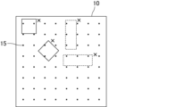
- FIG. 2 is a schematic diagram showing an example of arrangement of intertwined points in the mat material of the present invention.
- FIG. 3 is a schematic diagram showing an example of a mat member in which interlacing points are uniformly arranged.
- FIG. 4 is an example of an enlarged electron microscope image of the mat material of the present invention.
- FIG. 5 is another example of an enlarged electron microscope image of the mat material of the present invention.
- FIG. 6 is yet another example of an enlarged electron microscope image of the mat material of the present invention.
- FIG. 7 is still another example of an enlarged electron microscope image of the mat material of the present invention.
- FIG. 8 is a conceptual diagram schematically showing a shear fracture load testing apparatus.
- FIG. 8 is a conceptual diagram schematically showing a shear fracture load testing apparatus.
- FIG. 9 is a side view schematically showing an example of a measuring device for measuring the dispersibility of inorganic fibers.
- FIG. 10 is a plan view schematically showing part of a sample support arm that constitutes a measuring device for measuring the scattering properties of inorganic fibers.
- FIG. 11 is a perspective view schematically showing another example of the mat material of the present invention.
- FIG. 12 is a cross-sectional view schematically showing an example of the exhaust gas purifier of the present invention.
- the mat material of the present invention is a mat material made of inorganic fibers to which an inorganic binder and an organic binder are affixed, wherein the weight ratio of the inorganic binder to the weight of the entire mat material is w 1A , and the weight ratio of the organic binder is is w 1B , the ratio [w 1B /w 1A ] of the weight ratio w 1B of the organic binder to the weight ratio w 1A of the inorganic binder satisfies the following condition (1) or (2). do. (1) 0 ⁇ w1B / w1A ⁇ 0.8 (2) 9 ⁇ w 1B /w 1A
- FIG. 1 is a perspective view schematically showing an example of the mat material of the present invention.
- the mat material 1 of the present invention has a predetermined length (indicated by arrow L in FIG. 1), width (indicated by arrow W in FIG. 1) and thickness (indicated by arrow W in FIG. 1). , indicated by an arrow T).
- a protrusion 11 is formed at one end of the mat 10 in the longitudinal direction, and a recess 12 is formed at the other end.
- the protrusions 11 and the recesses 12 of the mat 10 are shaped so that they are just fitted to each other when the mat 10 is wound around an exhaust gas treating body for assembling an exhaust gas purifying device, which will be described later.
- the mat used for the mat material of the present invention does not have to have projections and recesses at the ends. Further, the shape of the ends of the mat may be L-shaped so that the ends fit together when the mat material is wrapped around the object.
- the thickness of the mat is not particularly limited, it is preferably 2 to 40 mm. If the thickness of the mat exceeds 40 mm, the flexibility of the mat is lost, making it difficult to handle when winding the mat material around the exhaust gas treating body. In addition, winding wrinkles and cracks are likely to occur in the mat material. When the thickness of the mat is less than 2 mm, the holding power of the mat material is insufficient, and the exhaust gas treating body tends to fall off. In addition, when the volume of the exhaust gas treating body changes, the mat material becomes difficult to absorb the volume change of the exhaust gas treating body. Therefore, cracks and the like are likely to occur in the exhaust gas treating body.
- the mat contains inorganic fibers.
- the inorganic fibers are not particularly limited, but preferably consist of at least one selected from the group consisting of alumina fibers, silica fibers, alumina-silica fibers, mullite fibers, biosoluble fibers and glass fibers.
- the inorganic fiber is at least one of alumina fiber, silica fiber, alumina-silica fiber, and mullite fiber, the exhaust gas treating body is exposed to a sufficiently high temperature because of its excellent heat resistance. However, deterioration or the like does not occur, and the function as a mat material can be sufficiently maintained.
- the inorganic fiber is a biosoluble fiber, even if the scattered inorganic fiber is inhaled when fabricating an exhaust gas purifying device using a mat material, it will dissolve in the body, so it will be difficult for the worker. No harm to health.
- Alumina fibers may contain additives such as calcia, magnesia, and zirconia in addition to alumina.
- the mat can be produced by a needling method or a papermaking method.
- the inorganic fiber assembly produced by the needling method is also called a needle mat, and the mat produced by the papermaking method is also called a papermaking mat.
- the inorganic fibers preferably have an average fiber length of 1 to 150 mm, more preferably 10 to 80 mm.
- the average fiber length of the inorganic fibers is less than 1 mm, the fiber length of the inorganic fibers is too short, and the entanglement of the inorganic fibers becomes insufficient, the winding property around the exhaust gas treating body decreases, and the mat tends to crack.
- the average fiber length of the inorganic fibers exceeds 150 mm, the fiber length of the inorganic fibers is too long, so that the number of fibers constituting the mat decreases, and the denseness of the mat decreases. As a result, the shear strength of the mat material is lowered.
- the inorganic fibers preferably have an average fiber length of 200 to 20000 ⁇ m, more preferably 300 to 10000 ⁇ m, even more preferably 500 to 1500 ⁇ m.
- entangled points are formed on the surface or the back surface of the mat material.
- the density ⁇ of intertwined points is preferably in the range of 0.5/cm 2 ⁇ 18/cm 2 .
- the density ⁇ of the intertwined points is measured on the main surface having the higher density of intertwined points among the front surface and the back surface. is the density of
- At least one of the second regions, which are regions, is preferably arranged.
- the principal surface of the mat member for determining whether or not the first region and/or the second region are arranged is the same principal surface as the principal surface for measuring the density of the intertwined points.
- FIG. 2 is a schematic diagram showing an example of arrangement of intertwined points in the mat material of the present invention.
- a plurality of intertwined points 15 are unevenly arranged. Therefore, the first region 17, which is a 4 mm ⁇ 4 mm region (region indicated by a solid square in FIG. 2) where no intertwined points 15 exist, and a 3 mm ⁇ 8 mm region (in FIG. 2) where no intertwined points 15 exist , a region indicated by a dashed rectangle) is arranged. Note that FIG. 2 does not show all of the first area 17 and the second area 18 .
- FIG. 3 is a schematic diagram showing an example of a mat member in which interlacing points are uniformly arranged.
- the interlacing points 15 are evenly spaced at intervals of 2.8 mm.
- Both the 4 mm by 4 mm square and the 3 mm by 8 mm rectangle shown in FIG. 3 contain one or more entanglement points.
- a 4 mm ⁇ 4 mm square that does not correspond to the first region and a 3 mm ⁇ 8 mm rectangle that does not correspond to the second region are marked with “x”. Therefore, neither the first area nor the second area can be arranged on the mat member shown in FIG.
- a method for counting the number of first regions and second regions within a 25 mm ⁇ 25 mm region is as follows. (1) Find a 4 mm ⁇ 4 mm region (first region) in which no entanglement points are formed. At this time, the plurality of first regions are selected so as not to overlap each other. (2) Find a 3 mm ⁇ 8 mm region (second region) in which no entanglement points are formed. At this time, the plurality of second regions are selected so as not to overlap each other. However, the second area may overlap the first area. When the second region and the first region overlap each other, the area where no interlacing points are present becomes larger, so that the surface pressure of the mat material can be increased.
- a plurality of first regions and/or second regions are arranged in a region of 25 mm ⁇ 25 mm.
- the surface pressure of the mat material can be increased.
- a plurality of the first regions and/or the second regions are arranged when the total number of the first regions and the number of the second regions is 2 or more, and the plurality of the first regions It includes a case where a plurality of second regions are arranged, a case where a plurality of first regions and a plurality of second regions are arranged, and the like.
- a third area which is a 4 mm ⁇ 4 mm area in which four or more intertwining points are present, is arranged within a 25 mm ⁇ 25 mm area on the front surface or the back surface of the mat material.
- the third region is arranged, the inorganic fibers are strongly entangled with each other in this region, so that the shear strength of the mat material can be increased.
- the method of counting the number of the third regions within the 25 mm ⁇ 25 mm region is the same as the method of counting the number of the first regions described above.
- the mat material contains an inorganic binder (also referred to as an inorganic binder) and an organic binder (also referred to as an organic binder).
- an inorganic binder also referred to as an inorganic binder
- an organic binder also referred to as an organic binder
- the ratio [w 1B /w 1A ] of the weight ratio W 1B of the organic binder to the weight ratio w 1A of the inorganic binder is preferably 0 ⁇ w 1B /w 1A ⁇ 0.5. , 0 ⁇ w 1B /w 1A ⁇ 0.3, and more preferably 0 ⁇ w 1B /w 1A ⁇ 0.1.
- the ratio [w 1B /w 1A ] of the weight ratio w 1B of the organic binder to the weight ratio w 1A of the inorganic binder is preferably 10 ⁇ w 1B /w 1A , and 11 ⁇ w. More preferably, 1B /w 1A , and even more preferably 13 ⁇ w 1B /w 1A .
- the weight ratio w1A of the inorganic binder and the weight ratio w1B of the organic binder attached to the mat material can be measured by the following method. First, a sample of a constant weight is taken from the mat material, an organic solvent (eg, tetrahydrofuran) in which the organic binder dissolves is selected, and the organic binder is dissolved and separated from the sample using a Soxhlet extractor. At this time, the inorganic binder is separated from the sample together with the dissolved organic binder, and the organic binder and the inorganic binder are recovered in the organic solvent. The organic solvent containing the organic binder and the inorganic binder is placed in a crucible and heated to evaporate and remove the organic solvent.
- an organic solvent eg, tetrahydrofuran
- the residue left in the crucible is regarded as the total weight of the organic binder and the inorganic binder attached to the mat material. Further, the crucible is heat-treated at 600° C. for 1 hour to burn off the organic binder. Since the inorganic binder remains in the crucible, this is taken as the weight of the inorganic binder, and the difference from the weight of the residue before the heat treatment is taken as the weight of the organic binder.
- inorganic binders examples include alumina sol and silica sol.
- the weight ratio w 1A of the inorganic binder to the mat material is preferably more than 0 wt % and 10 wt % or less. When the weight ratio w1A of the inorganic binder to the mat material is within the above range, the holding power can be sufficiently increased.
- organic binders examples include acrylic resins, acrylate latexes, rubber latexes, water-soluble organic polymers such as carboxymethyl cellulose and polyvinyl alcohol, thermoplastic resins such as styrene resins, and thermosetting resins such as epoxy resins.
- the weight ratio w 1B of the organic binder to the mat material is preferably more than 0 wt % and 10 wt % or less.
- the holding power can be sufficiently increased.
- the contents of the organic binder and the inorganic binder contained in the mat material can be measured, for example, by the following method.
- First, the mat material whose content is to be measured is sampled as a constant weight sample.
- an organic solvent for example, tetrahydrofuran
- the organic binder contained in the sample dissolves is selected, and the organic binder is dissolved in a Soxhlet extractor and separated from the sample.
- the inorganic binder contained in the dissolved organic binder is also separated from the sample, and the organic binder and the inorganic binder are recovered in the organic solvent.
- an organic solvent composed of the organic binder and the inorganic binder is placed in a crucible, and heated to evaporate and remove the organic solvent.
- the residue remaining in the crucible is regarded as the total weight of the organic binder and the inorganic binder with respect to the matting material, and the content (% by weight) of the matting material is calculated.
- the crucible is heat-treated at 600° C. for 1 hour to burn off the organic binder. Since the inorganic binder remains in the crucible, this is regarded as the content (% by weight) of the inorganic binder with respect to the total of the organic binder and the inorganic binder, and the content is calculated. The remainder is the content (% by weight) of the organic binder.
- the total weight ratio of the inorganic binder and the organic binder to the mat material is preferably 0.01 wt % or more and 25 wt % or less, and is preferably 0.1 wt % or more. , 15 wt % or less.
- the inorganic binder and the organic binder are attached to the surfaces of the inorganic fibers in a dispersed state.
- the inorganic binder and the organic binder are attached to the surface of the inorganic fiber in a dispersed state, the inorganic binder is dispersed in the film formed by the organic binder. Since the film in such a state has excellent mechanical strength, it is possible to prevent the inorganic fibers from slipping and to increase the holding power.
- a coating layer made of a mixture of an inorganic binder and an organic binder is covered with a coating layer made of a mixture of an inorganic binder and an organic binder.
- a coating layer comprising a mixture of an inorganic binder and an organic binder has higher mechanical strength than a coating layer comprising only an organic binder. Therefore, peeling of the coating layer is unlikely to occur, and the frictional resistance between the inorganic fibers can be increased.
- the coating layer is preferably formed by continuous scaly mixture (mixture of inorganic binder and organic binder).
- scaly mixture mixture of inorganic binder and organic binder.
- FIG. 4 is an example of an enlarged electron microscope image of the mat material of the present invention.
- part of the surface of the inorganic fiber 20 is covered with a coating layer 30 made of a mixture of an inorganic binder and an organic binder.
- the coating layer 30 is formed by a continuous scaly mixture of an inorganic binder and an organic binder.
- a particulate mixture 40 of an inorganic binder and an organic binder is attached to the surfaces of the inorganic fibers 20 . Whether or not the coating layer and the particles are composed of a mixture of the inorganic binder and the organic binder can be confirmed by using both field observation with an electron microscope and elemental analysis.
- FIG. 5 is another example of an enlarged electron microscope image of the mat material of the present invention.
- part of the surface of the inorganic fiber 20 is covered with a coating layer 30 made of a mixture of an inorganic binder and an organic binder.
- the coating layer 30 is formed by a continuous scaly mixture of an inorganic binder and an organic binder.
- a particulate mixture 40 of an inorganic binder and an organic binder is attached to the surfaces of the inorganic fibers 20 .
- the thickness of the coating layer may be uniform, but may not be uniform.
- the shape of the coating layer whose thickness is not constant is also called a multi-step shape.
- the shape of the coating layer is multi-stepped, it can be said that the coating layer has unevenness on the surface, so that the frictional resistance between the inorganic fibers can be further increased.
- Whether the coating layer has unevenness on the surface can be determined by magnifying the surface of the inorganic fiber at a magnification of 3000 using a scanning electron microscope. It is determined by checking the presence or absence of unevenness on the surface of the
- FIG. 6 is yet another example of an enlarged electron microscope image of the mat material of the present invention.
- a portion of the surface of the inorganic fiber 20 is covered with a coating layer 30 made of a mixture of an inorganic binder and an organic binder.
- the thickness of the coating layer 30 is not uniform and is multi-stepped.
- a particulate mixture 40 of an inorganic binder and an organic binder is attached to the surfaces of the inorganic fibers 20 .
- Particles of a mixture of an inorganic binder and an organic binder are preferably attached to the surface of the coating layer.
- the frictional resistance between the inorganic fibers can be further increased compared to when the particles are not attached.
- FIG. 7 is still another example of an enlarged electron microscope image of the mat material of the present invention.
- part of the surface of the inorganic fiber 20 is covered with a coating layer 30 made of a mixture of an inorganic binder and an organic binder.
- the coating layer 30 is formed by a continuous scaly mixture of an inorganic binder and an organic binder.
- the thickness of the coating layer 30 is not uniform and is multi-stepped.
- a particulate mixture 40 of an inorganic binder and an organic binder is attached to the surface of the coating layer 30 .
- the matting material preferably further contains a polymeric dispersant.
- a polymeric dispersant When the matting material further contains a polymeric dispersant, it becomes easier to attach the organic binder and the inorganic binder to the surfaces of the inorganic fibers in a dispersed state.
- Polymeric dispersants include polycarboxylic acid and/or its salts, naphthalene sulfonate formalin condensate and/or its salts, polyacrylic acid and/or its salts, polymethacrylic acid and/or its salts, polyvinyl sulfone Hydrophilic synthetic polymeric substances such as anionic polymeric dispersants such as acids and/or salts thereof, nonionic polymeric dispersants such as polyvinyl alcohol, polyvinylpyrrolidone, and polyethylene glycol; gelatin, casein, water-soluble Naturally hydrophilic polymeric substances such as starch; hydrophilic semi-synthetic polymeric substances such as carboxymethyl cellulose; Among these, hydrophilic synthetic polymeric substances are preferred, and anionic polymeric dispersants are more preferred.
- polymeric dispersants may be used alone, or a plurality of types may be used in combination. Further, it may be a polymeric dispersant having both a structure exhibiting properties as an anionic polymeric dispersant and a structure exhibiting properties as a nonionic polymeric dispersant.
- an anionic polymeric dispersant having a number average molecular weight of 500 to 100,000 is particularly preferred.
- the content of the polymeric dispersant is preferably 50 to 1000 ppm with respect to the weight of the inorganic fiber.
- aggregates composed of the inorganic binder and the organic binder adhere to the surfaces of the inorganic fibers.
- Aggregates composed of an inorganic binder and an organic binder can form unevenness on the surface of the inorganic fibers, so that the friction between the inorganic fibers can be increased to improve the holding power.
- the mat material may further contain a flocculating agent. If the matting material further contains an aggregating agent, the organic binder and the inorganic binder can be easily adhered to the surface of the inorganic fibers in an agglomerated state.
- the inorganic binder and the organic binder attached to the surface of the inorganic fiber are dispersed or aggregated can be confirmed by observing the surface of the inorganic fiber with SEM-EDX or the like.
- the mat member of the present invention preferably has a shear modulus of 0.26 or more, which is obtained by dividing the shear breaking load by the relaxation surface pressure.
- the shear modulus is obtained by dividing the shear breaking load by the relaxation surface pressure.
- FIG. 8 is a conceptual diagram schematically showing a shear fracture load testing apparatus.
- test pieces 1a and 1b are arranged on both sides of a stainless steel plate 73, and the outside thereof is sandwiched between left jigs 71 and right jigs 72.
- a large number of projecting members 74 are provided on the surfaces of the left jig 71, the right jig 72, and the stainless steel plate 73, which are in contact with the test piece.
- test pieces 1 a and 1 b are fixed to the left jig 71 , the right jig 72 and the stainless steel plate 73 by being pierced by the projecting member 74 .
- the test piece is compressed until the bulk density (GBD) reaches 0.3 g/cm 3 .
- the stainless steel plate 73 is moved in the direction (upward) shown by the arrow in FIG. It cannot escape apart from pieces 1a and 1b. Therefore, when the test pieces 1a and 1b are subjected to a shear force equal to or greater than the shear fracture load of the test pieces, the test pieces 1a and 1b undergo shear failure. Obtain the shear force applied to the stainless steel plate when the test piece undergoes shear fracture.
- the shear breaking load (kPa) can be obtained.
- the shear breaking load may be measured using a test piece obtained by cutting out a part of the mat material.
- the relaxation surface pressure can be measured by the following procedure. First, at room temperature, the mat material is compressed to a bulk density of 0.3 g/cm 3 , held for 20 minutes, and then the load is measured.
- the relaxation surface pressure (kPa) can be obtained by dividing the obtained load by the area of the test piece. Alternatively, the relaxation surface pressure may be measured using a test piece obtained by cutting out a part of the mat material.
- the mat material of the present invention has a fiber scattering rate (wt %) of 0.35 wt % or less in a scattering test.
- the scattering test is performed in the following procedure. First, the mat material is cut into a size of 100 mm ⁇ 100 mm to obtain a sample 210 for the scattering property test. For this scattering test sample, the scattering rate of the inorganic fibers can be measured using the measuring apparatus shown in FIGS. 9 and 10.
- FIG. FIG. 9 is a side view schematically showing an example of a measuring device for measuring the scattering properties of inorganic fibers
- FIG. 10 shows a sample support arm that constitutes the measuring device for measuring the scattering properties of inorganic fibers. is a plan view schematically showing a part of.
- the test apparatus 200 has a sample support arm 270 connected to the upper ends of two columns 260 vertically provided on a base 250 so that the sample support arm 270 can rotate within a predetermined range. . Furthermore, a vertical wall member 290 is fixed between the two columns at a position where it can collide with the sample support arm.
- FIG. 10 is a plan view schematically showing an example of a sample supporting arm portion of a measuring device for measuring the scattering properties of inorganic fibers. As shown in FIG. 10, the other end of the sample support arm 270 is fixed by a sample fixing member 280 connecting the ends of the sample support arm 270 .
- sample fixing member 280 there is another sample fixing member 280 at a fixed distance in the direction of the support 260 from the sample fixing member 280 connected to the end of the sample supporting arm 270, and the two sample supporting arms 270 are at least It is connected by a sample fixing member at two points.
- the sample support arm 270 is locked by a predetermined locking mechanism, and the scattering test sample 210 is fixed to the sample fixing member 280 with the clip 220 .
- the sample support arm 270 is unlocked, the sample support arm 270 and the spatter test sample 210 start falling toward the base 250 fixing the support 260.
- the sample support arm 270 collides with the vertical wall member 290 at the point where the sample support arm 270 and the post 260 are parallel, turning around the joint. Due to this collision, some of the inorganic fibers forming the scattering test sample 210 are broken and scattered.
- Fiber scattering rate (wt%) (weight of scattering test sample before test - weight of scattering test sample after test) / (weight of scattering test sample before test) x 100 (1)
- the mat material may further have a protective sheet placed on at least one surface.
- a protective sheet is placed on at least one surface of the mat.
- the material constituting the protective sheet is not particularly limited, a flexible resin such as polypropylene is preferable.
- the protective sheet may be, for example, a nonwoven fabric made of flexible resin fibers.
- two or more different materials may be used together for the protective sheet.
- Two or more types of materials may form the same nonwoven fabric, or two or more different types of nonwoven fabrics may be laminated to form a protective sheet.
- the thickness of the protective sheet is not particularly limited, it is preferably 1 ⁇ m to 1 mm. If the thickness of the protective sheet is less than 1 ⁇ m, the effect of alleviating deformation of the mat may not be sufficient. If the thickness of the protective sheet exceeds 1 mm, the handleability may deteriorate.
- the ratio of the thickness of the protective sheet to the thickness of the mat is not particularly limited, but is preferably in the range of about 1:10 to about 1:1000, and in the range of about 1:50 to about 1:200. is more preferred.
- the method of adhering the protective sheet and the mat is not particularly limited, but for example, a method of heating and melting hot-melt powder placed between the protective sheet and the mat can be used.
- the surface on which the protective sheet is installed is the outer surface when the mat material is wound around the exhaust gas treating body.
- a slit may be formed in the protective sheet.
- the direction of the slit is not particularly limited, it may extend along the longitudinal direction of the mat member or along the width direction.
- FIG. 11 is a perspective view schematically showing another example of the mat material of the present invention.
- a mat member 2 shown in FIG. 11 has a mat 10 and a protective sheet 50 provided on one surface of the mat 10 .
- the protective sheet may be provided only on one surface of the mat, or may be provided on both surfaces.
- An exhaust gas purifying apparatus of the present invention includes an exhaust gas treating body, a metal casing for housing the exhaust gas treating body, and a mat material disposed between the exhaust gas treating body and the metal casing for holding the exhaust gas treating body.
- the exhaust gas purifying apparatus is provided, wherein the mat material is the mat material of the present invention.
- the exhaust gas purifying device of the present invention can stably hold the exhaust gas treating body.
- FIG. 12 is a cross-sectional view schematically showing an example of the exhaust gas purifier of the present invention.
- the exhaust gas purification apparatus 100 includes a metal casing 120, an exhaust gas treating body 130 housed in the metal casing 120, and a mat material 1 disposed between the exhaust gas treating body 130 and the metal casing 120. It has The mat material 1 is the mat material of the present invention.
- the exhaust gas treating body 130 has a columnar shape in which a large number of cells 131 are arranged side by side in the longitudinal direction with cell walls 132 interposed therebetween.
- An introduction pipe for introducing the exhaust gas discharged from the internal combustion engine and an exhaust pipe for discharging the exhaust gas that has passed through the exhaust gas purifier are connected to the ends of the metal casing 120 as necessary.
- an exhaust gas filter in which one of each cell is plugged with a plugging material 133 is used as the exhaust gas treating body 130.
- a catalyst carrier that is not plugged with a sealing material may also be used.
- the exhaust gas discharged from the internal combustion engine and flowing into the exhaust gas purifying device 100 is an exhaust gas treating body (honeycomb filter) 130.
- the exhaust gas flows into one cell 131 opened at the exhaust gas inflow side end face 130 a of the second cell 131 and passes through the cell wall 132 separating the cells 131 .
- the PM in the exhaust gas is captured by the cell walls 132, and the exhaust gas is purified.
- the purified exhaust gas flows out from another cell 131 opened at the exhaust gas outlet side end surface 130b and is discharged to the outside.
- a first embodiment of the method for producing a mat material of the present invention comprises a needle mat preparation step of preparing an inorganic fiber aggregate made of inorganic fibers by a needling method, and attaching an inorganic binder and an organic binder to the inorganic fiber aggregate.
- a method for producing a matting material comprising an attaching step, wherein the weight ratio of the inorganic binder used in the attaching step is w2A , and the weight ratio of the organic binder is w2B .
- the ratio [w 2B /w 2A ] of the weight ratio w 2B of the binder satisfies the following condition (3) or (4). (3) 0 ⁇ w2B / w2A ⁇ 0.8 (4) 9 ⁇ w2B / w2A
- a method of preparing an inorganic fiber assembly by a needling method includes, for example, a spinning step of producing an inorganic fiber precursor by spinning a spinning mixture containing at least an inorganic compound and an organic polymer; A compression step of compressing to produce a sheet-like material, a needle punching step of performing needle punching treatment on at least one surface of the sheet-like material to prepare a needle-punched body, and firing the needle-punched body and a firing step.
- spinning process a spinning mixture containing at least an inorganic compound and an organic polymer is spun to produce an inorganic fiber precursor.
- an inorganic fiber precursor having an average fiber diameter of 3 to 10 ⁇ m is produced by spinning a spinning mixture containing a basic aluminum chloride aqueous solution and silica sol as raw materials by a blowing method.
- the inorganic fiber precursor obtained in the spinning step is compressed to produce a continuous sheet-like material having a predetermined size.
- needle punching process In the needle-punching step, at least one surface of the sheet-like material obtained in the compression step is needle-punched to produce a needle-punched body.
- the needle punching step it is preferable to set the needle arrangement density to 0.5 needles/cm 2 or more and less than 18 needles/cm 2 .
- the positions where the needles are arranged in the needle punching process correspond to the entanglement points in the mat material. Therefore, by setting the arrangement density of the needles to 0.5/cm 2 or more and less than 18/cm 2 , the density ⁇ of the intertwined points can be reduced to 0.5/cm 2 ⁇ ⁇ by a single needle punching process.
- a mat material in the range of ⁇ 18 pieces/cm 2 can be obtained.
- the arrangement density of the needles is not limited to the above range.
- the arrangement of the intertwined points formed in the needle-punched body is unevenly arranged, and the density ⁇ of the intertwined points is 0.5/cm. 2 ⁇ ⁇ ⁇ 18 pieces / cm 2 , in a 25 mm ⁇ 25 mm area, a 4 mm ⁇ 4 mm area (first area) where no intertwined points exist and / or a 3 mm ⁇ 8 mm area where no intertwined points exist A region (second region) can be formed.
- a method of intentionally biasing the arrangement of the intertwined points for example, after performing needle punching treatment so that the intertwined points are uniformly arranged
- a method of additionally performing needling treatment on a part can be mentioned.
- a method of performing needle punching treatment multiple times while moving the inorganic fiber precursor a method of performing needle punching treatment using a needle board in which needles are not arranged at equal intervals, and the like can be used.
- the needles may or may not penetrate the sheet-like material in the thickness direction.
- the needle-punched body is fired to obtain an inorganic fiber aggregate made of inorganic fibers.
- the temperature for firing the needle-punched body is not particularly limited, it is preferably 1000.degree. C. to 1600.degree.
- the inorganic fiber assembly (needle mat) prepared by the needling method is not attached with an inorganic binder or an organic binder.
- an attachment step of attaching an inorganic binder and/or an organic binder to the inorganic fiber aggregate is performed.
- a method for attaching the inorganic binder and the organic binder to the inorganic fiber aggregate for example, a method of contacting the inorganic fiber aggregate with a binder mixed liquid obtained by mixing a solvent, an inorganic binder and an organic binder, and then drying the mixture can be mentioned. be done.
- a method for bringing the binder mixed liquid into contact with the inorganic fiber aggregate for example, the inorganic fiber aggregate is immersed in the binder mixed liquid, or the binder mixed liquid is dropped onto the inorganic fiber aggregate by a method such as a curtain coating method. and the like.
- the weight of the inorganic binder and the organic binder used in the impregnation step is the weight ratio of the inorganic binder to the weight ratio of the organic binder w2A , where w2A is the weight ratio of the inorganic binder to the binder mixture and w2B is the weight ratio of the organic binder.
- the ratio [w 2B /w 2A ] of the weight ratio w 2B of satisfies the following condition (3) or (4). (3) 0 ⁇ w2B / w2A ⁇ 0.8 (4) 9 ⁇ w2B / w2A
- an inorganic binder and an organic binder are adhered to an inorganic fiber aggregate to which no inorganic binder or organic binder is adhered. Therefore, by adjusting the ratio [w 2B /w 2A ] of the weight ratio w 2B of the organic binder to the weight ratio w 2A of the inorganic binder so as to satisfy the above condition (3) or (4), the You can get a mat material.
- the ratio [w 2B /w 2A ] of the weight ratio w 2B of the organic binder to the weight ratio w 2A of the inorganic binder is 0 ⁇ w 2B / It is preferable that w 2A ⁇ 0.5, more preferably 0 ⁇ w 2B /w 2A ⁇ 0.3, and even more preferably 0 ⁇ w 2B /w 2A ⁇ 0.1.
- the ratio [w 2B /w 2A ] of the weight ratio w 2B of the organic binder to the weight ratio w 2A of the inorganic binder is 10 ⁇ w 2B / w 2A is preferred, 11 ⁇ w 2B /w 2A is more preferred, and 13 ⁇ w 2B /w 2A is even more preferred.
- a polymer-based dispersant may be contained in the binder mixture used in the attachment step.
- the binder mixed liquid contains a polymeric dispersant
- the inorganic binder and the organic binder are dispersed in the binder mixed liquid. That is, the binder mixed liquid becomes a dispersion liquid in which the inorganic binder and the organic binder are dispersed in the dispersion medium.
- the binder mixture (dispersion) in this state into contact with the aggregate of inorganic fibers, the inorganic binder and the organic binder can be attached to the surface of the inorganic fibers in a dispersed state.
- the binder liquid mixture used in the attachment step may contain a flocculating agent. If the binder mixed liquid contains a flocculant, the inorganic binder and the organic binder will be flocculated in the mixed liquid. That is, the binder mixed liquid becomes an aggregate dispersion liquid in which aggregates formed by aggregation of the inorganic binder and the organic binder are dispersed in the dispersion medium. By bringing the mixed liquid (coagulated dispersion liquid) in this state into contact with the aggregate of inorganic fibers, the inorganic binder and the organic binder can be adhered to the surfaces of the inorganic fibers in an aggregated state.
- the attachment of the inorganic binder and the attachment of the organic binder may be performed separately.
- a method of applying the inorganic binder and the organic binder separately for example, an inorganic binder mixed liquid containing an inorganic binder is brought into contact with an inorganic fiber aggregate to adhere the inorganic binder, and then an organic binder containing an organic binder is further applied.
- a method of attaching an organic binder by bringing it into contact with a binder mixture may be used.
- the order of adhering the inorganic binder and the organic binder is not particularly limited, and the inorganic binder may come first, or the organic binder may come first.
- a second embodiment of the method for producing a mat material of the present invention comprises a fiber opening step of opening inorganic fibers, and mixing the opened inorganic fibers with a solvent, an inorganic binder and an organic binder to prepare a slurry.
- a method for producing a mat material comprising a slurry preparation step, a paper making step of making the slurry into paper to obtain an inorganic fiber paper product, and a drying step of drying the inorganic fiber paper product, wherein the mat material is prepared in the slurry preparation step.
- the ratio of the weight ratio w3B of the organic binder to the weight ratio w3A of the inorganic binder [ w3B / w 3A ] satisfies the following condition (5) or (6). (5) 0 ⁇ w3B / w3A ⁇ 0.8 (6) 9 ⁇ w3B / w3A
- the inorganic fibers are made into short fibers (also referred to as fiber opening) by a pulverizer such as a feather mill, a stirrer such as a pulper, or the like, and adjusted to a desired fiber length.
- a pulverizer such as a feather mill
- a stirrer such as a pulper, or the like
- the short-fiber inorganic fibers may be subjected to a classification treatment as necessary, and it is preferable to perform a classification treatment to remove some or all of the inorganic fibers having a fiber length of 200 ⁇ m or less.
- classification treatment examples include classification treatment using a dry centrifugal classifier (also referred to as a dry cyclone), a wet centrifugal classifier (also referred to as a wet cyclone), and the like.
- a dry centrifugal classifier also referred to as a dry cyclone
- a wet centrifugal classifier also referred to as a wet cyclone
- the spread inorganic fibers are mixed with a solvent, an inorganic binder and an organic binder to prepare a slurry.
- the weight ratio of the inorganic binder contained in the slurry to be prepared is w 3A and the weight ratio of the organic binder is w 3B
- the weight ratio of the organic binder w 3B to the weight ratio w 3A of the inorganic binder is determined.
- a slurry is prepared so that the ratio [w 3B /w 3A ] satisfies the following condition (5) or (6). (5) 0 ⁇ w3B / w3A ⁇ 0.8 (6) 9 ⁇ w3B / w3A
- the order of mixing the inorganic binder and the organic binder is not particularly limited, but it is preferable to first mix the inorganic fibers and the inorganic binder, allow the mixture to stand for a while, and then add the organic binder.
- the inorganic binder is reliably adhered to the surfaces of the inorganic fibers, so that the friction between the inorganic fibers can be increased and the surface pressure can be improved.
- an aggregate obtained by aggregating an organic binder and an inorganic binder with a flocculant may be added to the slurry.
- the inorganic fiber paper-making body is obtained by pouring the slurry into a molding machine having a mesh for filtration formed on the bottom surface and then removing the solvent in the slurry.
- the solvent removal treatment is not particularly limited as long as the solvent contained in the inorganic fiber paper product can be removed.
- the solvent can be removed by means of compression, rotation, suction, pressure reduction, or the like.
- the inorganic fiber paper product is dried while being compressed using a method such as compression drying with a hot plate using a press dryer or the like.
- the step of adhering an inorganic binder and/or an organic binder to the mat after the drying step is unnecessary.
- the ratio [w 1B /w 1A ] of the weight ratio w 1B of the organic binder to the weight ratio w 1A of the inorganic binder attached to the mat after attachment satisfies the following condition (1) or (2):
- a step of adhering an inorganic binder and/or an organic binder to the mat after the drying step may be performed.
- a mixture was prepared.
- the resulting mixed liquid was concentrated to obtain a spinning mixture, and this spinning mixture was spun by a blowing method to produce an inorganic fiber precursor having an average fiber diameter of 5.1 ⁇ m.
- Needle punching step The sheet material obtained in the above (a-2) compression step was continuously subjected to needle punching treatment under the following conditions to produce a needle punched body. .
- a needle board with needles attached at a density of 9 needles/cm 2 was prepared.
- the needle board is disposed above one surface of the sheet material, and needle punching is performed by moving the needle board up and down once along the thickness direction of the sheet material. was made. At this time, the needle was pierced until the barb formed at the tip of the needle completely protruded from the opposite surface of the sheet-like material.
- (a-4) Firing step The needle-punched body obtained in the above (a-3) needle-punching step is continuously fired at a maximum temperature of 1250°C to contain alumina and silica in a ratio of 72 parts by weight to 28 parts by weight.
- a sintered sheet material made of inorganic fibers was produced.
- the inorganic fibers had an average fiber diameter of 5.1 ⁇ m and a minimum fiber diameter of 3.2 ⁇ m.
- the fired sheet material thus obtained had a bulk density of 0.15 g/cm 3 and a basis weight of 1400 g/m 2 .
- the density ⁇ of intertwined points was 9/cm 2 .
- An inorganic fiber assembly (needle mat) was produced by cutting the baked needle-punched body. No inorganic binder or organic binder was attached to the obtained inorganic fiber aggregate.
- Alumina is diluted with water, a polymer-based dispersant is added, and the solid content concentration of the inorganic particles is 2.0 wt% by sufficiently stirring.
- An inorganic binder mixture was prepared with a polymer dispersant concentration of 1000 ppm.
- Binder mixed solution preparing step The inorganic binder mixed solution obtained in the above (a-5-2) inorganic binder mixed solution preparing step is added in the above (a-5-1) organic binder mixed solution preparing step.
- the obtained organic binder mixed solution was added so that the weight ratio was 1:1 and sufficiently stirred, and the organic binder was 0.10 wt% in solid content concentration, the inorganic binder was 1.0 wt% in solid content concentration, and the above-mentioned high A binder mixture with a molecular dispersant concentration of 500 ppm was prepared.
- (a-5-4) Contacting step
- the binder mixture obtained in the above (a-5-3) binder mixture preparation step is subjected to a curtain coating method to form the inorganic fiber aggregate obtained in the (a-4) baking step.
- (a-5-5) Dehydration step
- the inorganic fiber assembly provided with the binder mixture obtained in the contact step (a-5-4) is sucked and dehydrated with a dehydrator to remove the binder mixture. , 100 parts by weight of the inorganic fiber was added to obtain a mat.
- Example 2 (a-5-1)
- the mat according to Example 2 was prepared in the same manner as in Example 1, except that the solid content concentration of the organic binder mixture prepared in the organic binder mixture preparation step was changed to 0.66 wt%. material was produced.
- Example 3 (a-5-1)
- the mat according to Example 3 was prepared in the same manner as in Example 1, except that the solid content concentration of the organic binder mixture prepared in the organic binder mixture preparation step was changed to 1.60 wt%. material was produced.
- Example 4 (a-5-1) The mat according to Example 4 was prepared in the same manner as in Example 1, except that the solid content concentration of the organic binder mixture prepared in the organic binder mixture preparation step was changed to 18.0 wt%. material was produced.
- Example 5 (a-5-1) The mat according to Example 5 was prepared in the same manner as in Example 1, except that the solid content concentration of the organic binder mixture prepared in the organic binder mixture preparation step was changed to 20.0 wt%. material was produced.
- Comparative example 1 (a-5-1) A mat material according to Comparative Example 1 was prepared in the same manner as in Example 1, except that the solid content concentration of the organic binder mixture prepared in the organic binder mixture preparation step was changed to 0 wt%. made.
- Comparative example 2 (a-5-1) The mat according to Comparative Example 2 was prepared in the same manner as in Example 1, except that the solid content concentration of the organic binder mixture prepared in the organic binder mixture preparation step was changed to 2.0 wt%. material was produced.
- Comparative Example 3 (a-5-1) A mat according to Comparative Example 3 was prepared in the same manner as in Example 1, except that the solid content concentration of the organic binder mixture prepared in the organic binder mixture preparation step was changed to 4.0 wt%. material was produced.
- Comparative Example 4 (a-5-1) The mat according to Comparative Example 4 was prepared in the same manner as in Example 1, except that the solid content concentration of the organic binder mixture prepared in the organic binder mixture preparation step was changed to 10.0 wt%. material was produced.
- Comparative Example 5 (a-5-1) The mat according to Comparative Example 5 was prepared in the same manner as in Example 1, except that the solid content concentration of the organic binder mixture prepared in the organic binder mixture preparation step was changed to 16.0 wt%. material was produced.
- the mat material of the present invention has a high shear modulus while suppressing scattering of inorganic fibers.
Landscapes
- Engineering & Computer Science (AREA)
- Chemical & Material Sciences (AREA)
- Chemical Kinetics & Catalysis (AREA)
- Textile Engineering (AREA)
- Mechanical Engineering (AREA)
- Health & Medical Sciences (AREA)
- Combustion & Propulsion (AREA)
- Biomedical Technology (AREA)
- Environmental & Geological Engineering (AREA)
- Analytical Chemistry (AREA)
- General Chemical & Material Sciences (AREA)
- Oil, Petroleum & Natural Gas (AREA)
- Inorganic Chemistry (AREA)
- Toxicology (AREA)
- General Engineering & Computer Science (AREA)
- Nonwoven Fabrics (AREA)
Abstract
La présente invention concerne un matériau de matelas qui est composé de fibres inorganiques qui sont imprégnées d'un liant inorganique et d'un liant organique, et qui est caractérisé en ce que si w1A est le rapport pondéral du liant inorganique sur le poids de l'ensemble du matériau de matelas et w1B est le rapport pondéral du liant organique sur le poids de l'ensemble du matériau de matelas, le rapport (w1B/w1A) du rapport pondéral w1B du liant organique sur le rapport pondéral w1A du liant inorganique satisfait la condition (1) ou (2) décrite ci-dessous. (1) : 0 < w1B/w1A ≤ 0,8 (2) : 9 ≤ w1B/w1A
Applications Claiming Priority (2)
| Application Number | Priority Date | Filing Date | Title |
|---|---|---|---|
| JP2022029961 | 2022-02-28 | ||
| JP2022-029961 | 2022-02-28 |
Publications (1)
| Publication Number | Publication Date |
|---|---|
| WO2023163009A1 true WO2023163009A1 (fr) | 2023-08-31 |
Family
ID=87765987
Family Applications (1)
| Application Number | Title | Priority Date | Filing Date |
|---|---|---|---|
| PCT/JP2023/006349 WO2023163009A1 (fr) | 2022-02-28 | 2023-02-22 | Matériau de matelas, dispositif de purification de gaz d'échappement et procédé de production de matériau de matelas |
Country Status (1)
| Country | Link |
|---|---|
| WO (1) | WO2023163009A1 (fr) |
Citations (7)
| Publication number | Priority date | Publication date | Assignee | Title |
|---|---|---|---|---|
| JP2001065337A (ja) * | 1999-08-23 | 2001-03-13 | Ibiden Co Ltd | 触媒コンバータ |
| JP2002066331A (ja) * | 2000-08-25 | 2002-03-05 | Nichias Corp | 触媒担体保持部材及びその製造方法並びに触媒コンバータ |
| JP2003266572A (ja) * | 2002-03-20 | 2003-09-24 | Nichias Corp | 防音断熱材およびその製造方法 |
| US20140248814A1 (en) * | 2011-10-06 | 2014-09-04 | Zoltek Companies, Inc. | Composite flame barrier |
| JP2014190191A (ja) * | 2013-03-26 | 2014-10-06 | Ibiden Co Ltd | 排ガス浄化装置用の保持シール材、該保持シール材の製造方法、排ガス浄化装置、及び、排ガス浄化装置の製造方法 |
| WO2015045636A1 (fr) * | 2013-09-24 | 2015-04-02 | イビデン株式会社 | Matériau d'étanchéité de retenue, procédé de production de matériau d'étanchéité de retenue, procédé d'emmanchement à la presse de corps d'enroulement, et dispositif de purification de gaz d'échappement |
| WO2015170610A1 (fr) * | 2014-05-08 | 2015-11-12 | イビデン株式会社 | Matériau d'étanchéité de fixation, procédé de production de matériau d'étanchéité de fixation, et purificateur de gaz d'échappement |
-
2023
- 2023-02-22 WO PCT/JP2023/006349 patent/WO2023163009A1/fr unknown
Patent Citations (7)
| Publication number | Priority date | Publication date | Assignee | Title |
|---|---|---|---|---|
| JP2001065337A (ja) * | 1999-08-23 | 2001-03-13 | Ibiden Co Ltd | 触媒コンバータ |
| JP2002066331A (ja) * | 2000-08-25 | 2002-03-05 | Nichias Corp | 触媒担体保持部材及びその製造方法並びに触媒コンバータ |
| JP2003266572A (ja) * | 2002-03-20 | 2003-09-24 | Nichias Corp | 防音断熱材およびその製造方法 |
| US20140248814A1 (en) * | 2011-10-06 | 2014-09-04 | Zoltek Companies, Inc. | Composite flame barrier |
| JP2014190191A (ja) * | 2013-03-26 | 2014-10-06 | Ibiden Co Ltd | 排ガス浄化装置用の保持シール材、該保持シール材の製造方法、排ガス浄化装置、及び、排ガス浄化装置の製造方法 |
| WO2015045636A1 (fr) * | 2013-09-24 | 2015-04-02 | イビデン株式会社 | Matériau d'étanchéité de retenue, procédé de production de matériau d'étanchéité de retenue, procédé d'emmanchement à la presse de corps d'enroulement, et dispositif de purification de gaz d'échappement |
| WO2015170610A1 (fr) * | 2014-05-08 | 2015-11-12 | イビデン株式会社 | Matériau d'étanchéité de fixation, procédé de production de matériau d'étanchéité de fixation, et purificateur de gaz d'échappement |
Similar Documents
| Publication | Publication Date | Title |
|---|---|---|
| US7959867B2 (en) | Sheet member and manufacturing method of the same, and exhaust gas processing device | |
| JP6298452B2 (ja) | 保持シール材、保持シール材の製造方法及び排ガス浄化装置 | |
| JP5183296B2 (ja) | 保持シール材、保持シール材の製造方法及び排ガス浄化装置 | |
| JP5990393B2 (ja) | 保持シール材、及び、排ガス浄化装置 | |
| JP5926084B2 (ja) | 保持シール材、排ガス浄化装置及び保持シール材の製造方法 | |
| JP6419556B2 (ja) | 保持シール材及び排ガス浄化装置 | |
| EP2730760A1 (fr) | Matériau de scellage de fixation, son procédé de fabrication et appareil de purification de gaz d'échappement | |
| WO2022210181A1 (fr) | Mat, dispositif de purification de gaz d'échappement et procédé de fabrication de mat | |
| JP6218529B2 (ja) | 保持シール材、保持シール材の製造方法、排ガス浄化装置の製造方法、及び、排ガス浄化装置 | |
| EP3051185B1 (fr) | Procede de production d'un materiau de joint d'etancheite de support | |
| JP2015017344A (ja) | 無機繊維、無機繊維集合体の製造方法、保持シール材、及び、排ガス浄化装置 | |
| WO2023163009A1 (fr) | Matériau de matelas, dispositif de purification de gaz d'échappement et procédé de production de matériau de matelas | |
| JP6483408B2 (ja) | 保持シール材 | |
| JP6218528B2 (ja) | 保持シール材、保持シール材の製造方法、巻付体の圧入方法及び排ガス浄化装置 | |
| WO2023163007A1 (fr) | Matériau de matelas, dispositif de purification de gaz d'échappement et procédé de production de matériau de matelas | |
| WO2023238591A1 (fr) | Matériau de mat, appareil de purification de gaz d'échappement, et procédé de fabrication d'appareil de purification de gaz d'échappement | |
| JP6294148B2 (ja) | 保持シール材の製造方法 | |
| JP6294147B2 (ja) | 保持シール材、保持シール材の製造方法及び排ガス浄化装置 | |
| JP2016108397A (ja) | 保持シール材、排ガス浄化装置及び保持シール材の製造方法 | |
| JP2023074324A (ja) | マット材、排ガス浄化装置及びマット材の製造方法 | |
| JP2020097901A (ja) | 保持シール材及び保持シール材の製造方法 | |
| JP2023048673A (ja) | 保持シール材、保持シール材の製造方法及び排ガス浄化装置 |
Legal Events
| Date | Code | Title | Description |
|---|---|---|---|
| 121 | Ep: the epo has been informed by wipo that ep was designated in this application |
Ref document number: 23760009 Country of ref document: EP Kind code of ref document: A1 |