WO2023163009A1 - Mat material, exhaust gas purification device, and method for producing mat material - Google Patents
Mat material, exhaust gas purification device, and method for producing mat material Download PDFInfo
- Publication number
- WO2023163009A1 WO2023163009A1 PCT/JP2023/006349 JP2023006349W WO2023163009A1 WO 2023163009 A1 WO2023163009 A1 WO 2023163009A1 JP 2023006349 W JP2023006349 W JP 2023006349W WO 2023163009 A1 WO2023163009 A1 WO 2023163009A1
- Authority
- WO
- WIPO (PCT)
- Prior art keywords
- inorganic
- binder
- mat
- organic binder
- mat material
- Prior art date
Links
Images


Classifications
-
- B—PERFORMING OPERATIONS; TRANSPORTING
- B01—PHYSICAL OR CHEMICAL PROCESSES OR APPARATUS IN GENERAL
- B01D—SEPARATION
- B01D46/00—Filters or filtering processes specially modified for separating dispersed particles from gases or vapours
-
- B—PERFORMING OPERATIONS; TRANSPORTING
- B01—PHYSICAL OR CHEMICAL PROCESSES OR APPARATUS IN GENERAL
- B01D—SEPARATION
- B01D53/00—Separation of gases or vapours; Recovering vapours of volatile solvents from gases; Chemical or biological purification of waste gases, e.g. engine exhaust gases, smoke, fumes, flue gases, aerosols
- B01D53/34—Chemical or biological purification of waste gases
- B01D53/92—Chemical or biological purification of waste gases of engine exhaust gases
- B01D53/94—Chemical or biological purification of waste gases of engine exhaust gases by catalytic processes
-
- D—TEXTILES; PAPER
- D04—BRAIDING; LACE-MAKING; KNITTING; TRIMMINGS; NON-WOVEN FABRICS
- D04H—MAKING TEXTILE FABRICS, e.g. FROM FIBRES OR FILAMENTARY MATERIAL; FABRICS MADE BY SUCH PROCESSES OR APPARATUS, e.g. FELTS, NON-WOVEN FABRICS; COTTON-WOOL; WADDING ; NON-WOVEN FABRICS FROM STAPLE FIBRES, FILAMENTS OR YARNS, BONDED WITH AT LEAST ONE WEB-LIKE MATERIAL DURING THEIR CONSOLIDATION
- D04H1/00—Non-woven fabrics formed wholly or mainly of staple fibres or like relatively short fibres
- D04H1/40—Non-woven fabrics formed wholly or mainly of staple fibres or like relatively short fibres from fleeces or layers composed of fibres without existing or potential cohesive properties
- D04H1/42—Non-woven fabrics formed wholly or mainly of staple fibres or like relatively short fibres from fleeces or layers composed of fibres without existing or potential cohesive properties characterised by the use of certain kinds of fibres insofar as this use has no preponderant influence on the consolidation of the fleece
- D04H1/4209—Inorganic fibres
-
- D—TEXTILES; PAPER
- D04—BRAIDING; LACE-MAKING; KNITTING; TRIMMINGS; NON-WOVEN FABRICS
- D04H—MAKING TEXTILE FABRICS, e.g. FROM FIBRES OR FILAMENTARY MATERIAL; FABRICS MADE BY SUCH PROCESSES OR APPARATUS, e.g. FELTS, NON-WOVEN FABRICS; COTTON-WOOL; WADDING ; NON-WOVEN FABRICS FROM STAPLE FIBRES, FILAMENTS OR YARNS, BONDED WITH AT LEAST ONE WEB-LIKE MATERIAL DURING THEIR CONSOLIDATION
- D04H1/00—Non-woven fabrics formed wholly or mainly of staple fibres or like relatively short fibres
- D04H1/40—Non-woven fabrics formed wholly or mainly of staple fibres or like relatively short fibres from fleeces or layers composed of fibres without existing or potential cohesive properties
- D04H1/44—Non-woven fabrics formed wholly or mainly of staple fibres or like relatively short fibres from fleeces or layers composed of fibres without existing or potential cohesive properties the fleeces or layers being consolidated by mechanical means, e.g. by rolling
- D04H1/46—Non-woven fabrics formed wholly or mainly of staple fibres or like relatively short fibres from fleeces or layers composed of fibres without existing or potential cohesive properties the fleeces or layers being consolidated by mechanical means, e.g. by rolling by needling or like operations to cause entanglement of fibres
- D04H1/48—Non-woven fabrics formed wholly or mainly of staple fibres or like relatively short fibres from fleeces or layers composed of fibres without existing or potential cohesive properties the fleeces or layers being consolidated by mechanical means, e.g. by rolling by needling or like operations to cause entanglement of fibres in combination with at least one other method of consolidation
- D04H1/488—Non-woven fabrics formed wholly or mainly of staple fibres or like relatively short fibres from fleeces or layers composed of fibres without existing or potential cohesive properties the fleeces or layers being consolidated by mechanical means, e.g. by rolling by needling or like operations to cause entanglement of fibres in combination with at least one other method of consolidation in combination with bonding agents
-
- D—TEXTILES; PAPER
- D06—TREATMENT OF TEXTILES OR THE LIKE; LAUNDERING; FLEXIBLE MATERIALS NOT OTHERWISE PROVIDED FOR
- D06M—TREATMENT, NOT PROVIDED FOR ELSEWHERE IN CLASS D06, OF FIBRES, THREADS, YARNS, FABRICS, FEATHERS OR FIBROUS GOODS MADE FROM SUCH MATERIALS
- D06M11/00—Treating fibres, threads, yarns, fabrics or fibrous goods made from such materials, with inorganic substances or complexes thereof; Such treatment combined with mechanical treatment, e.g. mercerising
- D06M11/32—Treating fibres, threads, yarns, fabrics or fibrous goods made from such materials, with inorganic substances or complexes thereof; Such treatment combined with mechanical treatment, e.g. mercerising with oxygen, ozone, ozonides, oxides, hydroxides or percompounds; Salts derived from anions with an amphoteric element-oxygen bond
- D06M11/36—Treating fibres, threads, yarns, fabrics or fibrous goods made from such materials, with inorganic substances or complexes thereof; Such treatment combined with mechanical treatment, e.g. mercerising with oxygen, ozone, ozonides, oxides, hydroxides or percompounds; Salts derived from anions with an amphoteric element-oxygen bond with oxides, hydroxides or mixed oxides; with salts derived from anions with an amphoteric element-oxygen bond
- D06M11/45—Oxides or hydroxides of elements of Groups 3 or 13 of the Periodic System; Aluminates
-
- D—TEXTILES; PAPER
- D06—TREATMENT OF TEXTILES OR THE LIKE; LAUNDERING; FLEXIBLE MATERIALS NOT OTHERWISE PROVIDED FOR
- D06M—TREATMENT, NOT PROVIDED FOR ELSEWHERE IN CLASS D06, OF FIBRES, THREADS, YARNS, FABRICS, FEATHERS OR FIBROUS GOODS MADE FROM SUCH MATERIALS
- D06M11/00—Treating fibres, threads, yarns, fabrics or fibrous goods made from such materials, with inorganic substances or complexes thereof; Such treatment combined with mechanical treatment, e.g. mercerising
- D06M11/77—Treating fibres, threads, yarns, fabrics or fibrous goods made from such materials, with inorganic substances or complexes thereof; Such treatment combined with mechanical treatment, e.g. mercerising with silicon or compounds thereof
- D06M11/79—Treating fibres, threads, yarns, fabrics or fibrous goods made from such materials, with inorganic substances or complexes thereof; Such treatment combined with mechanical treatment, e.g. mercerising with silicon or compounds thereof with silicon dioxide, silicic acids or their salts
-
- D—TEXTILES; PAPER
- D06—TREATMENT OF TEXTILES OR THE LIKE; LAUNDERING; FLEXIBLE MATERIALS NOT OTHERWISE PROVIDED FOR
- D06M—TREATMENT, NOT PROVIDED FOR ELSEWHERE IN CLASS D06, OF FIBRES, THREADS, YARNS, FABRICS, FEATHERS OR FIBROUS GOODS MADE FROM SUCH MATERIALS
- D06M15/00—Treating fibres, threads, yarns, fabrics, or fibrous goods made from such materials, with macromolecular compounds; Such treatment combined with mechanical treatment
- D06M15/19—Treating fibres, threads, yarns, fabrics, or fibrous goods made from such materials, with macromolecular compounds; Such treatment combined with mechanical treatment with synthetic macromolecular compounds
- D06M15/21—Macromolecular compounds obtained by reactions only involving carbon-to-carbon unsaturated bonds
- D06M15/263—Macromolecular compounds obtained by reactions only involving carbon-to-carbon unsaturated bonds of unsaturated carboxylic acids; Salts or esters thereof
-
- F—MECHANICAL ENGINEERING; LIGHTING; HEATING; WEAPONS; BLASTING
- F01—MACHINES OR ENGINES IN GENERAL; ENGINE PLANTS IN GENERAL; STEAM ENGINES
- F01N—GAS-FLOW SILENCERS OR EXHAUST APPARATUS FOR MACHINES OR ENGINES IN GENERAL; GAS-FLOW SILENCERS OR EXHAUST APPARATUS FOR INTERNAL COMBUSTION ENGINES
- F01N3/00—Exhaust or silencing apparatus having means for purifying, rendering innocuous, or otherwise treating exhaust
- F01N3/08—Exhaust or silencing apparatus having means for purifying, rendering innocuous, or otherwise treating exhaust for rendering innocuous
- F01N3/10—Exhaust or silencing apparatus having means for purifying, rendering innocuous, or otherwise treating exhaust for rendering innocuous by thermal or catalytic conversion of noxious components of exhaust
- F01N3/24—Exhaust or silencing apparatus having means for purifying, rendering innocuous, or otherwise treating exhaust for rendering innocuous by thermal or catalytic conversion of noxious components of exhaust characterised by constructional aspects of converting apparatus
- F01N3/28—Construction of catalytic reactors
Definitions
- the present invention relates to a mat material, an exhaust gas purifier, and a method for manufacturing the mat material.
- Exhaust gas emitted from internal combustion engines such as diesel engines contains particulate matter (hereinafter also referred to as PM), and in recent years, it has become a problem that this PM harms the environment and the human body. .
- the exhaust gas contains harmful gas components such as CO, HC, and NOx, there are concerns about the effects of these harmful gas components on the environment and the human body.
- an exhaust gas treating body made of porous ceramic such as silicon carbide or cordierite, and a casing accommodating the exhaust gas treating body are provided. and a holding sealing material (mat material) disposed between an exhaust gas treating body and a casing.
- This holding sealing material prevents the exhaust gas treating body from coming into contact with and damaging the casing covering the outer periphery thereof due to vibrations and impacts caused by the running of the vehicle, and prevents the exhaust gas treating body and the casing from being damaged. It is arranged mainly for the purpose of preventing exhaust gas from leaking from between.
- Patent Document 1 discloses attaching an organic binder and an inorganic binder to a mat material made of inorganic fibers, and using the organic binder and the inorganic binder at a weight ratio of 1:1.
- the film of the binder layer composed of the organic binder and the inorganic binder can suppress scattering of the inorganic fibers.
- the inorganic binder and the organic binder are used at a weight ratio of 1:1, the friction between the inorganic fibers cannot be sufficiently increased, resulting in a low shear modulus.
- the higher this value the more stably the exhaust gas treating body can be held by the mat material.
- the mat material of the present invention is a mat material made of inorganic fibers to which an inorganic binder and an organic binder are affixed, wherein the weight ratio of the inorganic binder to the weight of the entire mat material is w 1A , and the weight ratio of the organic binder is
- the weight ratio is w 1B
- the ratio [w 1B / w 1A ] of the weight ratio w 1B of the organic binder to the weight ratio w 1A of the inorganic binder satisfies the following condition (1) or (2). Characterized by (1) 0 ⁇ w1B / w1A ⁇ 0.8 (2) 9 ⁇ w 1B /w 1A
- the ratio [w 1B /w 1A ] of the weight ratio w 1B of the organic binder to the weight ratio w 1A of the inorganic binder is (1) 0 ⁇ w 1B /w 1A ⁇ 0.8, or ( 2) 9 ⁇ w 1B /w 1A .
- the weight ratio of the organic binder is relatively large, so that the strength of the coating formed by the organic binder and the inorganic binder is increased, and slippage between the inorganic fibers can be suppressed.
- the inorganic binder and the organic binder are attached to the surfaces of the inorganic fibers in a dispersed state.
- the inorganic binder and the organic binder are attached to the surface of the inorganic fiber in a dispersed state, the inorganic binder is dispersed in the film formed by the organic binder. Since the coating in such a state has excellent mechanical strength, it is possible to prevent the inorganic fibers from slipping and increase the shear modulus of the mat material.
- the matting material of the present invention preferably further contains a polymeric dispersant.
- a polymeric dispersant it becomes easier to attach the organic binder and the inorganic binder to the surfaces of the inorganic fibers in a dispersed state.
- aggregates composed of the inorganic binder and the organic binder adhere to the surfaces of the inorganic fibers.
- Aggregates composed of an inorganic binder and an organic binder can form unevenness on the surface of the inorganic fibers, so that the friction between the inorganic fibers can be increased to improve the holding power.
- a coating layer made of a mixture of the inorganic binder and the organic binder is covered with a coating layer made of a mixture of the inorganic binder and the organic binder.
- a coating layer comprising a mixture of an inorganic binder and an organic binder has higher mechanical strength than a coating layer comprising only an organic binder. Therefore, peeling of the coating layer is unlikely to occur, and the frictional resistance between the inorganic fibers can be increased.
- the coating layer is formed by continuous scaly mixture of the inorganic binder and the organic binder.
- the coating layer is formed of the scaly mixture, a large number of irregularities derived from the scaly mixture are formed on the surface of the coating layer, and the frictional resistance between the inorganic fibers can be further increased.
- the shape of the coating layer is preferably multi-stepped.
- the frictional resistance between the inorganic fibers can be further increased.
- a particulate mixture of the inorganic binder and the organic binder adhere to the surface of the coating layer.
- the frictional resistance between the inorganic fibers can be further increased compared to the coating layer alone.
- the mat material of the present invention is preferably a needle mat having at least one of its front surface and back surface subjected to needling treatment.
- the mat material of the present invention has a plurality of intertwined points formed by needling treatment on at least one of the front surface and the back surface, and the density ⁇ of the intertwined points is 0.5 points/cm 2 ⁇ 18 points/ It is preferably in the range of cm 2 .
- the density ⁇ of the intertwined points is within the above range, the shear modulus can be improved.
- the mat material of the present invention has a plurality of intertwined points formed by needling on at least one of the front surface and the back surface, and is a 4 mm ⁇ 4 mm area in which no intertwined points exist within a 25 mm ⁇ 25 mm area. It is preferable that at least one of the first area and the second area, which is a 3 mm ⁇ 8 mm area in which no interlacing points exist, is arranged.
- a plurality of the first regions and/or the second regions are arranged within a region of 25 mm ⁇ 25 mm.
- the surface pressure of the mat material can be increased.
- the mat material of the present invention is preferably used in an exhaust gas purifier.
- the mat material of the present invention has a high shear modulus. Therefore, it can be suitably used for an exhaust gas purifier.
- the mat material of the present invention preferably has a shear modulus of 0.26 or more.
- the shear modulus is 0.26 or more, the mat material is less likely to be sheared when the exhaust gas treating body is press-fitted into the metal casing using the mat material of the present invention.
- the shear modulus is obtained by dividing the shear breaking load by the relaxation surface pressure. A method for measuring the shear breaking load and the relaxation surface pressure will be described later.
- the mat material of the present invention preferably further has a protective sheet provided on at least one surface. If the mat material further has a protective sheet provided on its surface, the mat material may be displaced and/or densely wrinkled when the mat material is wound around the exhaust gas treating body, and the gap between the fitting parts may occur. is suppressed.
- An exhaust gas purifying apparatus of the present invention includes an exhaust gas treating body, a metal casing for housing the exhaust gas treating body, and a mat material disposed between the exhaust gas treating body and the metal casing for holding the exhaust gas treating body.
- the exhaust gas purifying apparatus is provided, wherein the mat material is the mat material of the present invention.
- the exhaust gas purifying device of the present invention can stably hold the exhaust gas treating body.
- a first embodiment of the method for producing a mat material of the present invention comprises a needle mat preparation step of preparing an inorganic fiber aggregate made of inorganic fibers by a needling method, and attaching an inorganic binder and an organic binder to the inorganic fiber aggregate.
- a method for producing a matting material comprising an attaching step, wherein the weight ratio of the inorganic binder used in the attaching step is w2A , and the weight ratio of the organic binder is w2B .
- the ratio [w 2B /w 2A ] of the weight ratio w 2B of the binder satisfies the following condition (3) or (4). (3) 0 ⁇ w2B / w2A ⁇ 0.8 (4) 9 ⁇ w2B / w2A
- the inorganic fiber aggregate is attached with a dispersion liquid in which the inorganic binder and the organic binder are dispersed in a dispersion medium.
- the inorganic fiber aggregates are attached with an aggregation dispersion obtained by aggregation of the inorganic binder and the organic binder.
- a second embodiment of the method for producing a mat material of the present invention comprises a fiber opening step of opening inorganic fibers, and mixing the opened inorganic fibers with a solvent, an inorganic binder and an organic binder to prepare a slurry.
- a method for producing a mat material comprising a slurry preparation step, a paper making step of making the slurry into paper to obtain an inorganic fiber paper product, and a drying step of drying the inorganic fiber paper product, wherein the mat material is prepared in the slurry preparation step.
- the ratio of the weight ratio w3B of the organic binder to the weight ratio w3A of the inorganic binder [ w3B / w 3A ] satisfies the following condition (5) or (6). (5) 0 ⁇ w3B / w3A ⁇ 0.8 (6) 9 ⁇ w3B / w3A
- the mat member of the present invention can be produced easily.
- FIG. 1 is a perspective view schematically showing an example of the mat material of the present invention.
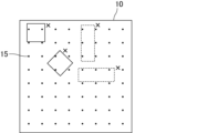
- FIG. 2 is a schematic diagram showing an example of arrangement of intertwined points in the mat material of the present invention.
- FIG. 3 is a schematic diagram showing an example of a mat member in which interlacing points are uniformly arranged.
- FIG. 4 is an example of an enlarged electron microscope image of the mat material of the present invention.
- FIG. 5 is another example of an enlarged electron microscope image of the mat material of the present invention.
- FIG. 6 is yet another example of an enlarged electron microscope image of the mat material of the present invention.
- FIG. 7 is still another example of an enlarged electron microscope image of the mat material of the present invention.
- FIG. 8 is a conceptual diagram schematically showing a shear fracture load testing apparatus.
- FIG. 8 is a conceptual diagram schematically showing a shear fracture load testing apparatus.
- FIG. 9 is a side view schematically showing an example of a measuring device for measuring the dispersibility of inorganic fibers.
- FIG. 10 is a plan view schematically showing part of a sample support arm that constitutes a measuring device for measuring the scattering properties of inorganic fibers.
- FIG. 11 is a perspective view schematically showing another example of the mat material of the present invention.
- FIG. 12 is a cross-sectional view schematically showing an example of the exhaust gas purifier of the present invention.
- the mat material of the present invention is a mat material made of inorganic fibers to which an inorganic binder and an organic binder are affixed, wherein the weight ratio of the inorganic binder to the weight of the entire mat material is w 1A , and the weight ratio of the organic binder is is w 1B , the ratio [w 1B /w 1A ] of the weight ratio w 1B of the organic binder to the weight ratio w 1A of the inorganic binder satisfies the following condition (1) or (2). do. (1) 0 ⁇ w1B / w1A ⁇ 0.8 (2) 9 ⁇ w 1B /w 1A
- FIG. 1 is a perspective view schematically showing an example of the mat material of the present invention.
- the mat material 1 of the present invention has a predetermined length (indicated by arrow L in FIG. 1), width (indicated by arrow W in FIG. 1) and thickness (indicated by arrow W in FIG. 1). , indicated by an arrow T).
- a protrusion 11 is formed at one end of the mat 10 in the longitudinal direction, and a recess 12 is formed at the other end.
- the protrusions 11 and the recesses 12 of the mat 10 are shaped so that they are just fitted to each other when the mat 10 is wound around an exhaust gas treating body for assembling an exhaust gas purifying device, which will be described later.
- the mat used for the mat material of the present invention does not have to have projections and recesses at the ends. Further, the shape of the ends of the mat may be L-shaped so that the ends fit together when the mat material is wrapped around the object.
- the thickness of the mat is not particularly limited, it is preferably 2 to 40 mm. If the thickness of the mat exceeds 40 mm, the flexibility of the mat is lost, making it difficult to handle when winding the mat material around the exhaust gas treating body. In addition, winding wrinkles and cracks are likely to occur in the mat material. When the thickness of the mat is less than 2 mm, the holding power of the mat material is insufficient, and the exhaust gas treating body tends to fall off. In addition, when the volume of the exhaust gas treating body changes, the mat material becomes difficult to absorb the volume change of the exhaust gas treating body. Therefore, cracks and the like are likely to occur in the exhaust gas treating body.
- the mat contains inorganic fibers.
- the inorganic fibers are not particularly limited, but preferably consist of at least one selected from the group consisting of alumina fibers, silica fibers, alumina-silica fibers, mullite fibers, biosoluble fibers and glass fibers.
- the inorganic fiber is at least one of alumina fiber, silica fiber, alumina-silica fiber, and mullite fiber, the exhaust gas treating body is exposed to a sufficiently high temperature because of its excellent heat resistance. However, deterioration or the like does not occur, and the function as a mat material can be sufficiently maintained.
- the inorganic fiber is a biosoluble fiber, even if the scattered inorganic fiber is inhaled when fabricating an exhaust gas purifying device using a mat material, it will dissolve in the body, so it will be difficult for the worker. No harm to health.
- Alumina fibers may contain additives such as calcia, magnesia, and zirconia in addition to alumina.
- the mat can be produced by a needling method or a papermaking method.
- the inorganic fiber assembly produced by the needling method is also called a needle mat, and the mat produced by the papermaking method is also called a papermaking mat.
- the inorganic fibers preferably have an average fiber length of 1 to 150 mm, more preferably 10 to 80 mm.
- the average fiber length of the inorganic fibers is less than 1 mm, the fiber length of the inorganic fibers is too short, and the entanglement of the inorganic fibers becomes insufficient, the winding property around the exhaust gas treating body decreases, and the mat tends to crack.
- the average fiber length of the inorganic fibers exceeds 150 mm, the fiber length of the inorganic fibers is too long, so that the number of fibers constituting the mat decreases, and the denseness of the mat decreases. As a result, the shear strength of the mat material is lowered.
- the inorganic fibers preferably have an average fiber length of 200 to 20000 ⁇ m, more preferably 300 to 10000 ⁇ m, even more preferably 500 to 1500 ⁇ m.
- entangled points are formed on the surface or the back surface of the mat material.
- the density ⁇ of intertwined points is preferably in the range of 0.5/cm 2 ⁇ 18/cm 2 .
- the density ⁇ of the intertwined points is measured on the main surface having the higher density of intertwined points among the front surface and the back surface. is the density of
- At least one of the second regions, which are regions, is preferably arranged.
- the principal surface of the mat member for determining whether or not the first region and/or the second region are arranged is the same principal surface as the principal surface for measuring the density of the intertwined points.
- FIG. 2 is a schematic diagram showing an example of arrangement of intertwined points in the mat material of the present invention.
- a plurality of intertwined points 15 are unevenly arranged. Therefore, the first region 17, which is a 4 mm ⁇ 4 mm region (region indicated by a solid square in FIG. 2) where no intertwined points 15 exist, and a 3 mm ⁇ 8 mm region (in FIG. 2) where no intertwined points 15 exist , a region indicated by a dashed rectangle) is arranged. Note that FIG. 2 does not show all of the first area 17 and the second area 18 .
- FIG. 3 is a schematic diagram showing an example of a mat member in which interlacing points are uniformly arranged.
- the interlacing points 15 are evenly spaced at intervals of 2.8 mm.
- Both the 4 mm by 4 mm square and the 3 mm by 8 mm rectangle shown in FIG. 3 contain one or more entanglement points.
- a 4 mm ⁇ 4 mm square that does not correspond to the first region and a 3 mm ⁇ 8 mm rectangle that does not correspond to the second region are marked with “x”. Therefore, neither the first area nor the second area can be arranged on the mat member shown in FIG.
- a method for counting the number of first regions and second regions within a 25 mm ⁇ 25 mm region is as follows. (1) Find a 4 mm ⁇ 4 mm region (first region) in which no entanglement points are formed. At this time, the plurality of first regions are selected so as not to overlap each other. (2) Find a 3 mm ⁇ 8 mm region (second region) in which no entanglement points are formed. At this time, the plurality of second regions are selected so as not to overlap each other. However, the second area may overlap the first area. When the second region and the first region overlap each other, the area where no interlacing points are present becomes larger, so that the surface pressure of the mat material can be increased.
- a plurality of first regions and/or second regions are arranged in a region of 25 mm ⁇ 25 mm.
- the surface pressure of the mat material can be increased.
- a plurality of the first regions and/or the second regions are arranged when the total number of the first regions and the number of the second regions is 2 or more, and the plurality of the first regions It includes a case where a plurality of second regions are arranged, a case where a plurality of first regions and a plurality of second regions are arranged, and the like.
- a third area which is a 4 mm ⁇ 4 mm area in which four or more intertwining points are present, is arranged within a 25 mm ⁇ 25 mm area on the front surface or the back surface of the mat material.
- the third region is arranged, the inorganic fibers are strongly entangled with each other in this region, so that the shear strength of the mat material can be increased.
- the method of counting the number of the third regions within the 25 mm ⁇ 25 mm region is the same as the method of counting the number of the first regions described above.
- the mat material contains an inorganic binder (also referred to as an inorganic binder) and an organic binder (also referred to as an organic binder).
- an inorganic binder also referred to as an inorganic binder
- an organic binder also referred to as an organic binder
- the ratio [w 1B /w 1A ] of the weight ratio W 1B of the organic binder to the weight ratio w 1A of the inorganic binder is preferably 0 ⁇ w 1B /w 1A ⁇ 0.5. , 0 ⁇ w 1B /w 1A ⁇ 0.3, and more preferably 0 ⁇ w 1B /w 1A ⁇ 0.1.
- the ratio [w 1B /w 1A ] of the weight ratio w 1B of the organic binder to the weight ratio w 1A of the inorganic binder is preferably 10 ⁇ w 1B /w 1A , and 11 ⁇ w. More preferably, 1B /w 1A , and even more preferably 13 ⁇ w 1B /w 1A .
- the weight ratio w1A of the inorganic binder and the weight ratio w1B of the organic binder attached to the mat material can be measured by the following method. First, a sample of a constant weight is taken from the mat material, an organic solvent (eg, tetrahydrofuran) in which the organic binder dissolves is selected, and the organic binder is dissolved and separated from the sample using a Soxhlet extractor. At this time, the inorganic binder is separated from the sample together with the dissolved organic binder, and the organic binder and the inorganic binder are recovered in the organic solvent. The organic solvent containing the organic binder and the inorganic binder is placed in a crucible and heated to evaporate and remove the organic solvent.
- an organic solvent eg, tetrahydrofuran
- the residue left in the crucible is regarded as the total weight of the organic binder and the inorganic binder attached to the mat material. Further, the crucible is heat-treated at 600° C. for 1 hour to burn off the organic binder. Since the inorganic binder remains in the crucible, this is taken as the weight of the inorganic binder, and the difference from the weight of the residue before the heat treatment is taken as the weight of the organic binder.
- inorganic binders examples include alumina sol and silica sol.
- the weight ratio w 1A of the inorganic binder to the mat material is preferably more than 0 wt % and 10 wt % or less. When the weight ratio w1A of the inorganic binder to the mat material is within the above range, the holding power can be sufficiently increased.
- organic binders examples include acrylic resins, acrylate latexes, rubber latexes, water-soluble organic polymers such as carboxymethyl cellulose and polyvinyl alcohol, thermoplastic resins such as styrene resins, and thermosetting resins such as epoxy resins.
- the weight ratio w 1B of the organic binder to the mat material is preferably more than 0 wt % and 10 wt % or less.
- the holding power can be sufficiently increased.
- the contents of the organic binder and the inorganic binder contained in the mat material can be measured, for example, by the following method.
- First, the mat material whose content is to be measured is sampled as a constant weight sample.
- an organic solvent for example, tetrahydrofuran
- the organic binder contained in the sample dissolves is selected, and the organic binder is dissolved in a Soxhlet extractor and separated from the sample.
- the inorganic binder contained in the dissolved organic binder is also separated from the sample, and the organic binder and the inorganic binder are recovered in the organic solvent.
- an organic solvent composed of the organic binder and the inorganic binder is placed in a crucible, and heated to evaporate and remove the organic solvent.
- the residue remaining in the crucible is regarded as the total weight of the organic binder and the inorganic binder with respect to the matting material, and the content (% by weight) of the matting material is calculated.
- the crucible is heat-treated at 600° C. for 1 hour to burn off the organic binder. Since the inorganic binder remains in the crucible, this is regarded as the content (% by weight) of the inorganic binder with respect to the total of the organic binder and the inorganic binder, and the content is calculated. The remainder is the content (% by weight) of the organic binder.
- the total weight ratio of the inorganic binder and the organic binder to the mat material is preferably 0.01 wt % or more and 25 wt % or less, and is preferably 0.1 wt % or more. , 15 wt % or less.
- the inorganic binder and the organic binder are attached to the surfaces of the inorganic fibers in a dispersed state.
- the inorganic binder and the organic binder are attached to the surface of the inorganic fiber in a dispersed state, the inorganic binder is dispersed in the film formed by the organic binder. Since the film in such a state has excellent mechanical strength, it is possible to prevent the inorganic fibers from slipping and to increase the holding power.
- a coating layer made of a mixture of an inorganic binder and an organic binder is covered with a coating layer made of a mixture of an inorganic binder and an organic binder.
- a coating layer comprising a mixture of an inorganic binder and an organic binder has higher mechanical strength than a coating layer comprising only an organic binder. Therefore, peeling of the coating layer is unlikely to occur, and the frictional resistance between the inorganic fibers can be increased.
- the coating layer is preferably formed by continuous scaly mixture (mixture of inorganic binder and organic binder).
- scaly mixture mixture of inorganic binder and organic binder.
- FIG. 4 is an example of an enlarged electron microscope image of the mat material of the present invention.
- part of the surface of the inorganic fiber 20 is covered with a coating layer 30 made of a mixture of an inorganic binder and an organic binder.
- the coating layer 30 is formed by a continuous scaly mixture of an inorganic binder and an organic binder.
- a particulate mixture 40 of an inorganic binder and an organic binder is attached to the surfaces of the inorganic fibers 20 . Whether or not the coating layer and the particles are composed of a mixture of the inorganic binder and the organic binder can be confirmed by using both field observation with an electron microscope and elemental analysis.
- FIG. 5 is another example of an enlarged electron microscope image of the mat material of the present invention.
- part of the surface of the inorganic fiber 20 is covered with a coating layer 30 made of a mixture of an inorganic binder and an organic binder.
- the coating layer 30 is formed by a continuous scaly mixture of an inorganic binder and an organic binder.
- a particulate mixture 40 of an inorganic binder and an organic binder is attached to the surfaces of the inorganic fibers 20 .
- the thickness of the coating layer may be uniform, but may not be uniform.
- the shape of the coating layer whose thickness is not constant is also called a multi-step shape.
- the shape of the coating layer is multi-stepped, it can be said that the coating layer has unevenness on the surface, so that the frictional resistance between the inorganic fibers can be further increased.
- Whether the coating layer has unevenness on the surface can be determined by magnifying the surface of the inorganic fiber at a magnification of 3000 using a scanning electron microscope. It is determined by checking the presence or absence of unevenness on the surface of the
- FIG. 6 is yet another example of an enlarged electron microscope image of the mat material of the present invention.
- a portion of the surface of the inorganic fiber 20 is covered with a coating layer 30 made of a mixture of an inorganic binder and an organic binder.
- the thickness of the coating layer 30 is not uniform and is multi-stepped.
- a particulate mixture 40 of an inorganic binder and an organic binder is attached to the surfaces of the inorganic fibers 20 .
- Particles of a mixture of an inorganic binder and an organic binder are preferably attached to the surface of the coating layer.
- the frictional resistance between the inorganic fibers can be further increased compared to when the particles are not attached.
- FIG. 7 is still another example of an enlarged electron microscope image of the mat material of the present invention.
- part of the surface of the inorganic fiber 20 is covered with a coating layer 30 made of a mixture of an inorganic binder and an organic binder.
- the coating layer 30 is formed by a continuous scaly mixture of an inorganic binder and an organic binder.
- the thickness of the coating layer 30 is not uniform and is multi-stepped.
- a particulate mixture 40 of an inorganic binder and an organic binder is attached to the surface of the coating layer 30 .
- the matting material preferably further contains a polymeric dispersant.
- a polymeric dispersant When the matting material further contains a polymeric dispersant, it becomes easier to attach the organic binder and the inorganic binder to the surfaces of the inorganic fibers in a dispersed state.
- Polymeric dispersants include polycarboxylic acid and/or its salts, naphthalene sulfonate formalin condensate and/or its salts, polyacrylic acid and/or its salts, polymethacrylic acid and/or its salts, polyvinyl sulfone Hydrophilic synthetic polymeric substances such as anionic polymeric dispersants such as acids and/or salts thereof, nonionic polymeric dispersants such as polyvinyl alcohol, polyvinylpyrrolidone, and polyethylene glycol; gelatin, casein, water-soluble Naturally hydrophilic polymeric substances such as starch; hydrophilic semi-synthetic polymeric substances such as carboxymethyl cellulose; Among these, hydrophilic synthetic polymeric substances are preferred, and anionic polymeric dispersants are more preferred.
- polymeric dispersants may be used alone, or a plurality of types may be used in combination. Further, it may be a polymeric dispersant having both a structure exhibiting properties as an anionic polymeric dispersant and a structure exhibiting properties as a nonionic polymeric dispersant.
- an anionic polymeric dispersant having a number average molecular weight of 500 to 100,000 is particularly preferred.
- the content of the polymeric dispersant is preferably 50 to 1000 ppm with respect to the weight of the inorganic fiber.
- aggregates composed of the inorganic binder and the organic binder adhere to the surfaces of the inorganic fibers.
- Aggregates composed of an inorganic binder and an organic binder can form unevenness on the surface of the inorganic fibers, so that the friction between the inorganic fibers can be increased to improve the holding power.
- the mat material may further contain a flocculating agent. If the matting material further contains an aggregating agent, the organic binder and the inorganic binder can be easily adhered to the surface of the inorganic fibers in an agglomerated state.
- the inorganic binder and the organic binder attached to the surface of the inorganic fiber are dispersed or aggregated can be confirmed by observing the surface of the inorganic fiber with SEM-EDX or the like.
- the mat member of the present invention preferably has a shear modulus of 0.26 or more, which is obtained by dividing the shear breaking load by the relaxation surface pressure.
- the shear modulus is obtained by dividing the shear breaking load by the relaxation surface pressure.
- FIG. 8 is a conceptual diagram schematically showing a shear fracture load testing apparatus.
- test pieces 1a and 1b are arranged on both sides of a stainless steel plate 73, and the outside thereof is sandwiched between left jigs 71 and right jigs 72.
- a large number of projecting members 74 are provided on the surfaces of the left jig 71, the right jig 72, and the stainless steel plate 73, which are in contact with the test piece.
- test pieces 1 a and 1 b are fixed to the left jig 71 , the right jig 72 and the stainless steel plate 73 by being pierced by the projecting member 74 .
- the test piece is compressed until the bulk density (GBD) reaches 0.3 g/cm 3 .
- the stainless steel plate 73 is moved in the direction (upward) shown by the arrow in FIG. It cannot escape apart from pieces 1a and 1b. Therefore, when the test pieces 1a and 1b are subjected to a shear force equal to or greater than the shear fracture load of the test pieces, the test pieces 1a and 1b undergo shear failure. Obtain the shear force applied to the stainless steel plate when the test piece undergoes shear fracture.
- the shear breaking load (kPa) can be obtained.
- the shear breaking load may be measured using a test piece obtained by cutting out a part of the mat material.
- the relaxation surface pressure can be measured by the following procedure. First, at room temperature, the mat material is compressed to a bulk density of 0.3 g/cm 3 , held for 20 minutes, and then the load is measured.
- the relaxation surface pressure (kPa) can be obtained by dividing the obtained load by the area of the test piece. Alternatively, the relaxation surface pressure may be measured using a test piece obtained by cutting out a part of the mat material.
- the mat material of the present invention has a fiber scattering rate (wt %) of 0.35 wt % or less in a scattering test.
- the scattering test is performed in the following procedure. First, the mat material is cut into a size of 100 mm ⁇ 100 mm to obtain a sample 210 for the scattering property test. For this scattering test sample, the scattering rate of the inorganic fibers can be measured using the measuring apparatus shown in FIGS. 9 and 10.
- FIG. FIG. 9 is a side view schematically showing an example of a measuring device for measuring the scattering properties of inorganic fibers
- FIG. 10 shows a sample support arm that constitutes the measuring device for measuring the scattering properties of inorganic fibers. is a plan view schematically showing a part of.
- the test apparatus 200 has a sample support arm 270 connected to the upper ends of two columns 260 vertically provided on a base 250 so that the sample support arm 270 can rotate within a predetermined range. . Furthermore, a vertical wall member 290 is fixed between the two columns at a position where it can collide with the sample support arm.
- FIG. 10 is a plan view schematically showing an example of a sample supporting arm portion of a measuring device for measuring the scattering properties of inorganic fibers. As shown in FIG. 10, the other end of the sample support arm 270 is fixed by a sample fixing member 280 connecting the ends of the sample support arm 270 .
- sample fixing member 280 there is another sample fixing member 280 at a fixed distance in the direction of the support 260 from the sample fixing member 280 connected to the end of the sample supporting arm 270, and the two sample supporting arms 270 are at least It is connected by a sample fixing member at two points.
- the sample support arm 270 is locked by a predetermined locking mechanism, and the scattering test sample 210 is fixed to the sample fixing member 280 with the clip 220 .
- the sample support arm 270 is unlocked, the sample support arm 270 and the spatter test sample 210 start falling toward the base 250 fixing the support 260.
- the sample support arm 270 collides with the vertical wall member 290 at the point where the sample support arm 270 and the post 260 are parallel, turning around the joint. Due to this collision, some of the inorganic fibers forming the scattering test sample 210 are broken and scattered.
- Fiber scattering rate (wt%) (weight of scattering test sample before test - weight of scattering test sample after test) / (weight of scattering test sample before test) x 100 (1)
- the mat material may further have a protective sheet placed on at least one surface.
- a protective sheet is placed on at least one surface of the mat.
- the material constituting the protective sheet is not particularly limited, a flexible resin such as polypropylene is preferable.
- the protective sheet may be, for example, a nonwoven fabric made of flexible resin fibers.
- two or more different materials may be used together for the protective sheet.
- Two or more types of materials may form the same nonwoven fabric, or two or more different types of nonwoven fabrics may be laminated to form a protective sheet.
- the thickness of the protective sheet is not particularly limited, it is preferably 1 ⁇ m to 1 mm. If the thickness of the protective sheet is less than 1 ⁇ m, the effect of alleviating deformation of the mat may not be sufficient. If the thickness of the protective sheet exceeds 1 mm, the handleability may deteriorate.
- the ratio of the thickness of the protective sheet to the thickness of the mat is not particularly limited, but is preferably in the range of about 1:10 to about 1:1000, and in the range of about 1:50 to about 1:200. is more preferred.
- the method of adhering the protective sheet and the mat is not particularly limited, but for example, a method of heating and melting hot-melt powder placed between the protective sheet and the mat can be used.
- the surface on which the protective sheet is installed is the outer surface when the mat material is wound around the exhaust gas treating body.
- a slit may be formed in the protective sheet.
- the direction of the slit is not particularly limited, it may extend along the longitudinal direction of the mat member or along the width direction.
- FIG. 11 is a perspective view schematically showing another example of the mat material of the present invention.
- a mat member 2 shown in FIG. 11 has a mat 10 and a protective sheet 50 provided on one surface of the mat 10 .
- the protective sheet may be provided only on one surface of the mat, or may be provided on both surfaces.
- An exhaust gas purifying apparatus of the present invention includes an exhaust gas treating body, a metal casing for housing the exhaust gas treating body, and a mat material disposed between the exhaust gas treating body and the metal casing for holding the exhaust gas treating body.
- the exhaust gas purifying apparatus is provided, wherein the mat material is the mat material of the present invention.
- the exhaust gas purifying device of the present invention can stably hold the exhaust gas treating body.
- FIG. 12 is a cross-sectional view schematically showing an example of the exhaust gas purifier of the present invention.
- the exhaust gas purification apparatus 100 includes a metal casing 120, an exhaust gas treating body 130 housed in the metal casing 120, and a mat material 1 disposed between the exhaust gas treating body 130 and the metal casing 120. It has The mat material 1 is the mat material of the present invention.
- the exhaust gas treating body 130 has a columnar shape in which a large number of cells 131 are arranged side by side in the longitudinal direction with cell walls 132 interposed therebetween.
- An introduction pipe for introducing the exhaust gas discharged from the internal combustion engine and an exhaust pipe for discharging the exhaust gas that has passed through the exhaust gas purifier are connected to the ends of the metal casing 120 as necessary.
- an exhaust gas filter in which one of each cell is plugged with a plugging material 133 is used as the exhaust gas treating body 130.
- a catalyst carrier that is not plugged with a sealing material may also be used.
- the exhaust gas discharged from the internal combustion engine and flowing into the exhaust gas purifying device 100 is an exhaust gas treating body (honeycomb filter) 130.
- the exhaust gas flows into one cell 131 opened at the exhaust gas inflow side end face 130 a of the second cell 131 and passes through the cell wall 132 separating the cells 131 .
- the PM in the exhaust gas is captured by the cell walls 132, and the exhaust gas is purified.
- the purified exhaust gas flows out from another cell 131 opened at the exhaust gas outlet side end surface 130b and is discharged to the outside.
- a first embodiment of the method for producing a mat material of the present invention comprises a needle mat preparation step of preparing an inorganic fiber aggregate made of inorganic fibers by a needling method, and attaching an inorganic binder and an organic binder to the inorganic fiber aggregate.
- a method for producing a matting material comprising an attaching step, wherein the weight ratio of the inorganic binder used in the attaching step is w2A , and the weight ratio of the organic binder is w2B .
- the ratio [w 2B /w 2A ] of the weight ratio w 2B of the binder satisfies the following condition (3) or (4). (3) 0 ⁇ w2B / w2A ⁇ 0.8 (4) 9 ⁇ w2B / w2A
- a method of preparing an inorganic fiber assembly by a needling method includes, for example, a spinning step of producing an inorganic fiber precursor by spinning a spinning mixture containing at least an inorganic compound and an organic polymer; A compression step of compressing to produce a sheet-like material, a needle punching step of performing needle punching treatment on at least one surface of the sheet-like material to prepare a needle-punched body, and firing the needle-punched body and a firing step.
- spinning process a spinning mixture containing at least an inorganic compound and an organic polymer is spun to produce an inorganic fiber precursor.
- an inorganic fiber precursor having an average fiber diameter of 3 to 10 ⁇ m is produced by spinning a spinning mixture containing a basic aluminum chloride aqueous solution and silica sol as raw materials by a blowing method.
- the inorganic fiber precursor obtained in the spinning step is compressed to produce a continuous sheet-like material having a predetermined size.
- needle punching process In the needle-punching step, at least one surface of the sheet-like material obtained in the compression step is needle-punched to produce a needle-punched body.
- the needle punching step it is preferable to set the needle arrangement density to 0.5 needles/cm 2 or more and less than 18 needles/cm 2 .
- the positions where the needles are arranged in the needle punching process correspond to the entanglement points in the mat material. Therefore, by setting the arrangement density of the needles to 0.5/cm 2 or more and less than 18/cm 2 , the density ⁇ of the intertwined points can be reduced to 0.5/cm 2 ⁇ ⁇ by a single needle punching process.
- a mat material in the range of ⁇ 18 pieces/cm 2 can be obtained.
- the arrangement density of the needles is not limited to the above range.
- the arrangement of the intertwined points formed in the needle-punched body is unevenly arranged, and the density ⁇ of the intertwined points is 0.5/cm. 2 ⁇ ⁇ ⁇ 18 pieces / cm 2 , in a 25 mm ⁇ 25 mm area, a 4 mm ⁇ 4 mm area (first area) where no intertwined points exist and / or a 3 mm ⁇ 8 mm area where no intertwined points exist A region (second region) can be formed.
- a method of intentionally biasing the arrangement of the intertwined points for example, after performing needle punching treatment so that the intertwined points are uniformly arranged
- a method of additionally performing needling treatment on a part can be mentioned.
- a method of performing needle punching treatment multiple times while moving the inorganic fiber precursor a method of performing needle punching treatment using a needle board in which needles are not arranged at equal intervals, and the like can be used.
- the needles may or may not penetrate the sheet-like material in the thickness direction.
- the needle-punched body is fired to obtain an inorganic fiber aggregate made of inorganic fibers.
- the temperature for firing the needle-punched body is not particularly limited, it is preferably 1000.degree. C. to 1600.degree.
- the inorganic fiber assembly (needle mat) prepared by the needling method is not attached with an inorganic binder or an organic binder.
- an attachment step of attaching an inorganic binder and/or an organic binder to the inorganic fiber aggregate is performed.
- a method for attaching the inorganic binder and the organic binder to the inorganic fiber aggregate for example, a method of contacting the inorganic fiber aggregate with a binder mixed liquid obtained by mixing a solvent, an inorganic binder and an organic binder, and then drying the mixture can be mentioned. be done.
- a method for bringing the binder mixed liquid into contact with the inorganic fiber aggregate for example, the inorganic fiber aggregate is immersed in the binder mixed liquid, or the binder mixed liquid is dropped onto the inorganic fiber aggregate by a method such as a curtain coating method. and the like.
- the weight of the inorganic binder and the organic binder used in the impregnation step is the weight ratio of the inorganic binder to the weight ratio of the organic binder w2A , where w2A is the weight ratio of the inorganic binder to the binder mixture and w2B is the weight ratio of the organic binder.
- the ratio [w 2B /w 2A ] of the weight ratio w 2B of satisfies the following condition (3) or (4). (3) 0 ⁇ w2B / w2A ⁇ 0.8 (4) 9 ⁇ w2B / w2A
- an inorganic binder and an organic binder are adhered to an inorganic fiber aggregate to which no inorganic binder or organic binder is adhered. Therefore, by adjusting the ratio [w 2B /w 2A ] of the weight ratio w 2B of the organic binder to the weight ratio w 2A of the inorganic binder so as to satisfy the above condition (3) or (4), the You can get a mat material.
- the ratio [w 2B /w 2A ] of the weight ratio w 2B of the organic binder to the weight ratio w 2A of the inorganic binder is 0 ⁇ w 2B / It is preferable that w 2A ⁇ 0.5, more preferably 0 ⁇ w 2B /w 2A ⁇ 0.3, and even more preferably 0 ⁇ w 2B /w 2A ⁇ 0.1.
- the ratio [w 2B /w 2A ] of the weight ratio w 2B of the organic binder to the weight ratio w 2A of the inorganic binder is 10 ⁇ w 2B / w 2A is preferred, 11 ⁇ w 2B /w 2A is more preferred, and 13 ⁇ w 2B /w 2A is even more preferred.
- a polymer-based dispersant may be contained in the binder mixture used in the attachment step.
- the binder mixed liquid contains a polymeric dispersant
- the inorganic binder and the organic binder are dispersed in the binder mixed liquid. That is, the binder mixed liquid becomes a dispersion liquid in which the inorganic binder and the organic binder are dispersed in the dispersion medium.
- the binder mixture (dispersion) in this state into contact with the aggregate of inorganic fibers, the inorganic binder and the organic binder can be attached to the surface of the inorganic fibers in a dispersed state.
- the binder liquid mixture used in the attachment step may contain a flocculating agent. If the binder mixed liquid contains a flocculant, the inorganic binder and the organic binder will be flocculated in the mixed liquid. That is, the binder mixed liquid becomes an aggregate dispersion liquid in which aggregates formed by aggregation of the inorganic binder and the organic binder are dispersed in the dispersion medium. By bringing the mixed liquid (coagulated dispersion liquid) in this state into contact with the aggregate of inorganic fibers, the inorganic binder and the organic binder can be adhered to the surfaces of the inorganic fibers in an aggregated state.
- the attachment of the inorganic binder and the attachment of the organic binder may be performed separately.
- a method of applying the inorganic binder and the organic binder separately for example, an inorganic binder mixed liquid containing an inorganic binder is brought into contact with an inorganic fiber aggregate to adhere the inorganic binder, and then an organic binder containing an organic binder is further applied.
- a method of attaching an organic binder by bringing it into contact with a binder mixture may be used.
- the order of adhering the inorganic binder and the organic binder is not particularly limited, and the inorganic binder may come first, or the organic binder may come first.
- a second embodiment of the method for producing a mat material of the present invention comprises a fiber opening step of opening inorganic fibers, and mixing the opened inorganic fibers with a solvent, an inorganic binder and an organic binder to prepare a slurry.
- a method for producing a mat material comprising a slurry preparation step, a paper making step of making the slurry into paper to obtain an inorganic fiber paper product, and a drying step of drying the inorganic fiber paper product, wherein the mat material is prepared in the slurry preparation step.
- the ratio of the weight ratio w3B of the organic binder to the weight ratio w3A of the inorganic binder [ w3B / w 3A ] satisfies the following condition (5) or (6). (5) 0 ⁇ w3B / w3A ⁇ 0.8 (6) 9 ⁇ w3B / w3A
- the inorganic fibers are made into short fibers (also referred to as fiber opening) by a pulverizer such as a feather mill, a stirrer such as a pulper, or the like, and adjusted to a desired fiber length.
- a pulverizer such as a feather mill
- a stirrer such as a pulper, or the like
- the short-fiber inorganic fibers may be subjected to a classification treatment as necessary, and it is preferable to perform a classification treatment to remove some or all of the inorganic fibers having a fiber length of 200 ⁇ m or less.
- classification treatment examples include classification treatment using a dry centrifugal classifier (also referred to as a dry cyclone), a wet centrifugal classifier (also referred to as a wet cyclone), and the like.
- a dry centrifugal classifier also referred to as a dry cyclone
- a wet centrifugal classifier also referred to as a wet cyclone
- the spread inorganic fibers are mixed with a solvent, an inorganic binder and an organic binder to prepare a slurry.
- the weight ratio of the inorganic binder contained in the slurry to be prepared is w 3A and the weight ratio of the organic binder is w 3B
- the weight ratio of the organic binder w 3B to the weight ratio w 3A of the inorganic binder is determined.
- a slurry is prepared so that the ratio [w 3B /w 3A ] satisfies the following condition (5) or (6). (5) 0 ⁇ w3B / w3A ⁇ 0.8 (6) 9 ⁇ w3B / w3A
- the order of mixing the inorganic binder and the organic binder is not particularly limited, but it is preferable to first mix the inorganic fibers and the inorganic binder, allow the mixture to stand for a while, and then add the organic binder.
- the inorganic binder is reliably adhered to the surfaces of the inorganic fibers, so that the friction between the inorganic fibers can be increased and the surface pressure can be improved.
- an aggregate obtained by aggregating an organic binder and an inorganic binder with a flocculant may be added to the slurry.
- the inorganic fiber paper-making body is obtained by pouring the slurry into a molding machine having a mesh for filtration formed on the bottom surface and then removing the solvent in the slurry.
- the solvent removal treatment is not particularly limited as long as the solvent contained in the inorganic fiber paper product can be removed.
- the solvent can be removed by means of compression, rotation, suction, pressure reduction, or the like.
- the inorganic fiber paper product is dried while being compressed using a method such as compression drying with a hot plate using a press dryer or the like.
- the step of adhering an inorganic binder and/or an organic binder to the mat after the drying step is unnecessary.
- the ratio [w 1B /w 1A ] of the weight ratio w 1B of the organic binder to the weight ratio w 1A of the inorganic binder attached to the mat after attachment satisfies the following condition (1) or (2):
- a step of adhering an inorganic binder and/or an organic binder to the mat after the drying step may be performed.
- a mixture was prepared.
- the resulting mixed liquid was concentrated to obtain a spinning mixture, and this spinning mixture was spun by a blowing method to produce an inorganic fiber precursor having an average fiber diameter of 5.1 ⁇ m.
- Needle punching step The sheet material obtained in the above (a-2) compression step was continuously subjected to needle punching treatment under the following conditions to produce a needle punched body. .
- a needle board with needles attached at a density of 9 needles/cm 2 was prepared.
- the needle board is disposed above one surface of the sheet material, and needle punching is performed by moving the needle board up and down once along the thickness direction of the sheet material. was made. At this time, the needle was pierced until the barb formed at the tip of the needle completely protruded from the opposite surface of the sheet-like material.
- (a-4) Firing step The needle-punched body obtained in the above (a-3) needle-punching step is continuously fired at a maximum temperature of 1250°C to contain alumina and silica in a ratio of 72 parts by weight to 28 parts by weight.
- a sintered sheet material made of inorganic fibers was produced.
- the inorganic fibers had an average fiber diameter of 5.1 ⁇ m and a minimum fiber diameter of 3.2 ⁇ m.
- the fired sheet material thus obtained had a bulk density of 0.15 g/cm 3 and a basis weight of 1400 g/m 2 .
- the density ⁇ of intertwined points was 9/cm 2 .
- An inorganic fiber assembly (needle mat) was produced by cutting the baked needle-punched body. No inorganic binder or organic binder was attached to the obtained inorganic fiber aggregate.
- Alumina is diluted with water, a polymer-based dispersant is added, and the solid content concentration of the inorganic particles is 2.0 wt% by sufficiently stirring.
- An inorganic binder mixture was prepared with a polymer dispersant concentration of 1000 ppm.
- Binder mixed solution preparing step The inorganic binder mixed solution obtained in the above (a-5-2) inorganic binder mixed solution preparing step is added in the above (a-5-1) organic binder mixed solution preparing step.
- the obtained organic binder mixed solution was added so that the weight ratio was 1:1 and sufficiently stirred, and the organic binder was 0.10 wt% in solid content concentration, the inorganic binder was 1.0 wt% in solid content concentration, and the above-mentioned high A binder mixture with a molecular dispersant concentration of 500 ppm was prepared.
- (a-5-4) Contacting step
- the binder mixture obtained in the above (a-5-3) binder mixture preparation step is subjected to a curtain coating method to form the inorganic fiber aggregate obtained in the (a-4) baking step.
- (a-5-5) Dehydration step
- the inorganic fiber assembly provided with the binder mixture obtained in the contact step (a-5-4) is sucked and dehydrated with a dehydrator to remove the binder mixture. , 100 parts by weight of the inorganic fiber was added to obtain a mat.
- Example 2 (a-5-1)
- the mat according to Example 2 was prepared in the same manner as in Example 1, except that the solid content concentration of the organic binder mixture prepared in the organic binder mixture preparation step was changed to 0.66 wt%. material was produced.
- Example 3 (a-5-1)
- the mat according to Example 3 was prepared in the same manner as in Example 1, except that the solid content concentration of the organic binder mixture prepared in the organic binder mixture preparation step was changed to 1.60 wt%. material was produced.
- Example 4 (a-5-1) The mat according to Example 4 was prepared in the same manner as in Example 1, except that the solid content concentration of the organic binder mixture prepared in the organic binder mixture preparation step was changed to 18.0 wt%. material was produced.
- Example 5 (a-5-1) The mat according to Example 5 was prepared in the same manner as in Example 1, except that the solid content concentration of the organic binder mixture prepared in the organic binder mixture preparation step was changed to 20.0 wt%. material was produced.
- Comparative example 1 (a-5-1) A mat material according to Comparative Example 1 was prepared in the same manner as in Example 1, except that the solid content concentration of the organic binder mixture prepared in the organic binder mixture preparation step was changed to 0 wt%. made.
- Comparative example 2 (a-5-1) The mat according to Comparative Example 2 was prepared in the same manner as in Example 1, except that the solid content concentration of the organic binder mixture prepared in the organic binder mixture preparation step was changed to 2.0 wt%. material was produced.
- Comparative Example 3 (a-5-1) A mat according to Comparative Example 3 was prepared in the same manner as in Example 1, except that the solid content concentration of the organic binder mixture prepared in the organic binder mixture preparation step was changed to 4.0 wt%. material was produced.
- Comparative Example 4 (a-5-1) The mat according to Comparative Example 4 was prepared in the same manner as in Example 1, except that the solid content concentration of the organic binder mixture prepared in the organic binder mixture preparation step was changed to 10.0 wt%. material was produced.
- Comparative Example 5 (a-5-1) The mat according to Comparative Example 5 was prepared in the same manner as in Example 1, except that the solid content concentration of the organic binder mixture prepared in the organic binder mixture preparation step was changed to 16.0 wt%. material was produced.
- the mat material of the present invention has a high shear modulus while suppressing scattering of inorganic fibers.
Abstract
The present invention provides a mat material which is composed of inorganic fibers that are impregnated with an inorganic binder and an organic binder, and which is characterized in that if w1A is the weight ratio of the inorganic binder to the weight of the whole mat material and w1B is the weight ratio of the organic binder to the weight of the whole mat material, the ratio (w1B/w1A) of the weight ratio w1B of the organic binder to the weight ratio w1A of the inorganic binder satisfies the condition (1) or (2) described below. (1): 0 < w1B/w1A ≤ 0.8 (2): 9 ≤ w1B/w1A
Description
本発明は、マット材、排ガス浄化装置及びマット材の製造方法に関する。
TECHNICAL FIELD The present invention relates to a mat material, an exhaust gas purifier, and a method for manufacturing the mat material.
ディーゼルエンジン等の内燃機関から排出される排ガス中には、パティキュレートマター(以下、PMともいう)が含まれており、近年、このPMが環境や人体に害を及ぼすことが問題となっている。また、排ガス中には、COやHC、NOx等の有害なガス成分も含まれていることから、この有害なガス成分が環境や人体に及ぼす影響についても懸念されている。
Exhaust gas emitted from internal combustion engines such as diesel engines contains particulate matter (hereinafter also referred to as PM), and in recent years, it has become a problem that this PM harms the environment and the human body. . In addition, since the exhaust gas contains harmful gas components such as CO, HC, and NOx, there are concerns about the effects of these harmful gas components on the environment and the human body.
そこで、排ガス中のPMを捕集したり、有害なガス成分を浄化したりする排ガス浄化装置として、炭化ケイ素やコージェライトなどの多孔質セラミックからなる排ガス処理体と、排ガス処理体を収容するケーシングと、排ガス処理体とケーシングとの間に配設される保持シール材(マット材)とから構成される排ガス浄化装置が種々提案されている。この保持シール材(マット材)は、自動車の走行等により生じる振動や衝撃により、排ガス処理体がその外周を覆うケーシングと接触して破損するのを防止することや、排ガス処理体とケーシングとの間から排ガスが漏れることを防止すること等を主な目的として配設されている。
Therefore, as an exhaust gas purifying device for capturing PM in exhaust gas and purifying harmful gas components, an exhaust gas treating body made of porous ceramic such as silicon carbide or cordierite, and a casing accommodating the exhaust gas treating body are provided. and a holding sealing material (mat material) disposed between an exhaust gas treating body and a casing. This holding sealing material (mat material) prevents the exhaust gas treating body from coming into contact with and damaging the casing covering the outer periphery thereof due to vibrations and impacts caused by the running of the vehicle, and prevents the exhaust gas treating body and the casing from being damaged. It is arranged mainly for the purpose of preventing exhaust gas from leaking from between.
特許文献1には、無機繊維からなるマット材に有機バインダ及び無機バインダを添着させること、及び、有機バインダと無機バインダを1:1の重量比で用いることを開示している。有機バインダと無機バインダからなる結合剤層の皮膜により、無機繊維の飛散を抑制することができる。
Patent Document 1 discloses attaching an organic binder and an inorganic binder to a mat material made of inorganic fibers, and using the organic binder and the inorganic binder at a weight ratio of 1:1. The film of the binder layer composed of the organic binder and the inorganic binder can suppress scattering of the inorganic fibers.
しかしながら、無機バインダと有機バインダを1:1の重量比で用いると、無機繊維同士の摩擦を充分に増加させることができず、せん断係数が低いという問題があった。この値が高いほど、マット材によって排ガス処理体を安定的に保持することができる。
However, when the inorganic binder and the organic binder are used at a weight ratio of 1:1, the friction between the inorganic fibers cannot be sufficiently increased, resulting in a low shear modulus. The higher this value, the more stably the exhaust gas treating body can be held by the mat material.
本発明は、上記問題を鑑みてなされたものであり、無機繊維の飛散を抑制しつつ、せん断係数の高いマット材を提供することを目的とする。
SUMMARY OF THE INVENTION It is an object of the present invention to provide a mat material that suppresses scattering of inorganic fibers and has a high shear modulus.
すなわち、本発明のマット材は、無機バインダ及び有機バインダが添着された、無機繊維からなるマット材であって、上記マット材全体の重量に対する上記無機バインダの重量割合をw1A、上記有機バインダの重量割合をw1Bとしたときに、無機バインダの重量割合w1Aに対する有機バインダの重量割合w1Bの比[w1B/w1A]が、以下の条件(1)又は(2)を満たすことを特徴とする。
(1)0<w1B/w1A≦0.8
(2)9≦w1B/w1A That is, the mat material of the present invention is a mat material made of inorganic fibers to which an inorganic binder and an organic binder are affixed, wherein the weight ratio of the inorganic binder to the weight of the entire mat material is w 1A , and the weight ratio of the organic binder is When the weight ratio is w 1B , the ratio [w 1B / w 1A ] of the weight ratio w 1B of the organic binder to the weight ratio w 1A of the inorganic binder satisfies the following condition (1) or (2). Characterized by
(1) 0< w1B / w1A≤0.8
(2) 9≦w 1B /w 1A
本発明のマット材は、無機バインダの重量割合w1Aに対する有機バインダの重量割合w1Bの比[w1B/w1A]が、(1)0<w1B/w1A≦0.8、又は(2)9≦w1B/w1Aを満たす。
In the mat material of the present invention, the ratio [w 1B /w 1A ] of the weight ratio w 1B of the organic binder to the weight ratio w 1A of the inorganic binder is (1) 0<w 1B /w 1A ≦0.8, or ( 2) 9≦w 1B /w 1A .
条件(1)を満たす場合、無機バインダの重量割合が相対的に多いため、無機繊維の表面に無機バインダ由来の凹凸を形成することで無機繊維同士の滑りを抑制することができる。
When the condition (1) is satisfied, since the weight ratio of the inorganic binder is relatively large, slippage between the inorganic fibers can be suppressed by forming irregularities derived from the inorganic binder on the surfaces of the inorganic fibers.
条件(2)を満たす場合、有機バインダの重量割合が相対的に多いため、有機バインダ及び無機バインダにより形成される被膜の強度が高まり、無機繊維同士の滑りを抑制することができる。
When the condition (2) is satisfied, the weight ratio of the organic binder is relatively large, so that the strength of the coating formed by the organic binder and the inorganic binder is increased, and slippage between the inorganic fibers can be suppressed.
無機バインダの重量割合w1Aに対する有機バインダの重量割合w1Bの比[w1B/w1A]が0.8を超えて9未満の場合には、無機バインダによる無機繊維表面への凹凸の形成、及び、有機バインダによる皮膜の強度増加のいずれの効果も充分に発揮されない。
When the ratio [w 1B /w 1A ] of the weight ratio w 1B of the organic binder to the weight ratio w 1A of the inorganic binder is more than 0.8 and less than 9, formation of irregularities on the inorganic fiber surface by the inorganic binder, In addition, neither effect of increasing the strength of the film due to the organic binder is exhibited sufficiently.
本発明のマット材においては、上記無機バインダ及び上記有機バインダが、それぞれ分散した状態で、上記無機繊維の表面に添着していることが好ましい。
無機バインダ及び有機バインダがそれぞれ分散した状態で無機繊維の表面に添着していると、有機バインダによって形成される被膜中に、無機バインダが分散した状態となる。このような状態の被膜は機械的強度に優れるため、無機繊維同士が滑ることを防止し、マット材のせん断係数を高めることができる。 In the mat material of the present invention, it is preferable that the inorganic binder and the organic binder are attached to the surfaces of the inorganic fibers in a dispersed state.
When the inorganic binder and the organic binder are attached to the surface of the inorganic fiber in a dispersed state, the inorganic binder is dispersed in the film formed by the organic binder. Since the coating in such a state has excellent mechanical strength, it is possible to prevent the inorganic fibers from slipping and increase the shear modulus of the mat material.
本発明のマット材は、さらに高分子系分散剤を含有していることが好ましい。
マット材がさらに高分子系分散剤を含有していると、無機繊維の表面に、有機バインダ及び無機バインダを分散した状態で添着させやすくなる。 The matting material of the present invention preferably further contains a polymeric dispersant.
When the matting material further contains a polymeric dispersant, it becomes easier to attach the organic binder and the inorganic binder to the surfaces of the inorganic fibers in a dispersed state.
本発明のマット材は、上記無機バインダ及び上記有機バインダからなる凝集体が、上記無機繊維の表面に添着していることが好ましい。
無機バインダ及び有機バインダからなる凝集体は、無機繊維の表面に凹凸を形成することができるため、無機繊維同士の摩擦を高めて保持力を向上させることができる。 In the mat material of the present invention, it is preferable that aggregates composed of the inorganic binder and the organic binder adhere to the surfaces of the inorganic fibers.
Aggregates composed of an inorganic binder and an organic binder can form unevenness on the surface of the inorganic fibers, so that the friction between the inorganic fibers can be increased to improve the holding power.
本発明のマット材において、上記無機繊維の表面の少なくとも一部を、上記無機バインダと上記有機バインダの混合物からなる被覆層が覆っていることが好ましい。
無機バインダと有機バインダの混合物からなる被覆層は、有機バインダのみで構成される被覆層と比較して機械的強度が高い。そのため、被覆層の剥がれが生じにくく、無機繊維同士の摩擦抵抗を高めることができる。 In the mat material of the present invention, it is preferable that at least part of the surfaces of the inorganic fibers is covered with a coating layer made of a mixture of the inorganic binder and the organic binder.
A coating layer comprising a mixture of an inorganic binder and an organic binder has higher mechanical strength than a coating layer comprising only an organic binder. Therefore, peeling of the coating layer is unlikely to occur, and the frictional resistance between the inorganic fibers can be increased.
本発明のマット材において、上記被覆層は、上記無機バインダと上記有機バインダの鱗片状の混合物が連続することにより形成されていることが好ましい。
被覆層が鱗片状の上記混合物で形成されていると、被覆層の表面に鱗片状の混合物に由来する凹凸が多数形成され、無機繊維同士の摩擦抵抗をさらに高めることができる。 In the mat material of the present invention, it is preferable that the coating layer is formed by continuous scaly mixture of the inorganic binder and the organic binder.
When the coating layer is formed of the scaly mixture, a large number of irregularities derived from the scaly mixture are formed on the surface of the coating layer, and the frictional resistance between the inorganic fibers can be further increased.
本発明のマット材において、上記被覆層の形状は多段状であることが好ましい。
被覆層の形状が多段状であると、無機繊維同士の摩擦抵抗をさらに高めることができる。 In the mat material of the present invention, the shape of the coating layer is preferably multi-stepped.
When the shape of the coating layer is multi-stepped, the frictional resistance between the inorganic fibers can be further increased.
被覆層の形状が多段状であると、無機繊維同士の摩擦抵抗をさらに高めることができる。 In the mat material of the present invention, the shape of the coating layer is preferably multi-stepped.
When the shape of the coating layer is multi-stepped, the frictional resistance between the inorganic fibers can be further increased.
本発明のマット材において、上記被覆層の表面には、上記無機バインダと上記有機バインダの粒子状の混合物が付着していることが好ましい。
被覆層の表面に無機バインダと有機バインダの粒子状の混合物が付着していると、被覆層単独の場合と比較して、無機繊維同士の摩擦抵抗をさらに高めることができる。 In the mat material of the present invention, it is preferable that a particulate mixture of the inorganic binder and the organic binder adhere to the surface of the coating layer.
When the particulate mixture of the inorganic binder and the organic binder is attached to the surface of the coating layer, the frictional resistance between the inorganic fibers can be further increased compared to the coating layer alone.
本発明のマット材は、表面または裏面の少なくとも一方にニードリング処理が施されたニードルマットであることが好ましい。
The mat material of the present invention is preferably a needle mat having at least one of its front surface and back surface subjected to needling treatment.
本発明のマット材は、表面または裏面の少なくとも一方にニードリング処理によって形成された複数の交絡点を有し、上記交絡点の密度ρは、0.5個/cm2≦ρ<18個/cm2の範囲にあることが好ましい。
交絡点の密度ρが上記範囲であると、せん断係数を向上させることができる。 The mat material of the present invention has a plurality of intertwined points formed by needling treatment on at least one of the front surface and the back surface, and the density ρ of the intertwined points is 0.5 points/cm 2 ≦ρ<18 points/ It is preferably in the range of cm 2 .
When the density ρ of the intertwined points is within the above range, the shear modulus can be improved.
本発明のマット材は、表面または裏面の少なくとも一方にニードリング処理によって形成された複数の交絡点を有し、25mm×25mmの領域内に、上記交絡点が存在しない4mm×4mmの領域である第1の領域、及び、上記交絡点が存在しない3mm×8mmの領域である第2の領域の少なくとも一方が配置されていることが好ましい。
The mat material of the present invention has a plurality of intertwined points formed by needling on at least one of the front surface and the back surface, and is a 4 mm×4 mm area in which no intertwined points exist within a 25 mm×25 mm area. It is preferable that at least one of the first area and the second area, which is a 3 mm×8 mm area in which no interlacing points exist, is arranged.
本発明のマット材は、25mm×25mmの領域内に、上記第1の領域及び/又は上記第2の領域が複数配置されていることが好ましい。
25mm×25mmの領域内に、第1の領域及び/又は第2の領域が複数配置されていると、マット材の面圧を高くすることができる。 In the mat material of the present invention, it is preferable that a plurality of the first regions and/or the second regions are arranged within a region of 25 mm×25 mm.
When a plurality of first regions and/or second regions are arranged within a region of 25 mm×25 mm, the surface pressure of the mat material can be increased.
本発明のマット材は、排ガス浄化装置に用いられることが好ましい。
本発明のマット材は、せん断係数が高い。そのため、排ガス浄化装置に好適に用いることができる。 The mat material of the present invention is preferably used in an exhaust gas purifier.
The mat material of the present invention has a high shear modulus. Therefore, it can be suitably used for an exhaust gas purifier.
本発明のマット材は、せん断係数が高い。そのため、排ガス浄化装置に好適に用いることができる。 The mat material of the present invention is preferably used in an exhaust gas purifier.
The mat material of the present invention has a high shear modulus. Therefore, it can be suitably used for an exhaust gas purifier.
本発明のマット材は、せん断係数が、0.26以上であることが好ましい。
せん断係数が0.26以上であると、本発明のマット材を用いて排ガス処理体を金属ケーシングに圧入する際に、マット材にせん断が生じにくい。
せん断係数は、せん断破壊荷重を緩和面圧で除することにより求められる。
せん断破壊荷重及び緩和面圧の測定方法は後述する。 The mat material of the present invention preferably has a shear modulus of 0.26 or more.
When the shear modulus is 0.26 or more, the mat material is less likely to be sheared when the exhaust gas treating body is press-fitted into the metal casing using the mat material of the present invention.
The shear modulus is obtained by dividing the shear breaking load by the relaxation surface pressure.
A method for measuring the shear breaking load and the relaxation surface pressure will be described later.
本発明のマット材は、少なくとも一方の表面に設置された保護シートをさらに有することが好ましい。
マット材が、その表面に設置された保護シートをさらに有していると、マット材を排ガス処理体に巻回した際の、マット材の位置ずれ及び/又は密集シワ、ならびに嵌合部の隙間の発生が抑制される。 The mat material of the present invention preferably further has a protective sheet provided on at least one surface.
If the mat material further has a protective sheet provided on its surface, the mat material may be displaced and/or densely wrinkled when the mat material is wound around the exhaust gas treating body, and the gap between the fitting parts may occur. is suppressed.
本発明の排ガス浄化装置は、排ガス処理体と、上記排ガス処理体を収容する金属ケーシングと、上記排ガス処理体と上記金属ケーシングとの間に配置され、上記排ガス処理体を保持するマット材とを備える排ガス浄化装置であって、上記マット材は、本発明のマット材であることを特徴とする。
An exhaust gas purifying apparatus of the present invention includes an exhaust gas treating body, a metal casing for housing the exhaust gas treating body, and a mat material disposed between the exhaust gas treating body and the metal casing for holding the exhaust gas treating body. The exhaust gas purifying apparatus is provided, wherein the mat material is the mat material of the present invention.
本発明の排ガス浄化装置は、本発明のマット材が排ガス処理体と金属ケーシングとの間に配置されているため、排ガス処理体を安定的に保持することができる。
Since the mat material of the present invention is arranged between the exhaust gas treating body and the metal casing, the exhaust gas purifying device of the present invention can stably hold the exhaust gas treating body.
本発明のマット材の製造方法の第一実施形態は、無機繊維からなる無機繊維集合体をニードリング法により準備するニードルマット準備工程と、上記無機繊維集合体に無機バインダ及び有機バインダを添着させる添着工程を有するマット材の製造方法であって、上記添着工程において用いられる無機バインダの重量割合をw2A、有機バインダの重量割合をw2Bとしたときに、無機バインダの重量割合w2Aに対する有機バインダの重量割合w2Bの比[w2B/w2A]が、以下の条件(3)又は(4)を満たすことを特徴とする。
(3)0<w2B/w2A≦0.8
(4)9≦w2B/w2A A first embodiment of the method for producing a mat material of the present invention comprises a needle mat preparation step of preparing an inorganic fiber aggregate made of inorganic fibers by a needling method, and attaching an inorganic binder and an organic binder to the inorganic fiber aggregate. A method for producing a matting material comprising an attaching step, wherein the weight ratio of the inorganic binder used in the attaching step is w2A , and the weight ratio of the organic binder is w2B . The ratio [w 2B /w 2A ] of the weight ratio w 2B of the binder satisfies the following condition (3) or (4).
(3) 0< w2B / w2A≤0.8
(4) 9≤w2B / w2A
本発明のマット材の製造方法の第一実施形態において、上記添着工程では、上記無機繊維集合体に、上記無機バインダ及び上記有機バインダが分散媒に分散してなる分散液を添着させることが好ましい。
In the first embodiment of the method for producing a mat material of the present invention, in the attaching step, it is preferable that the inorganic fiber aggregate is attached with a dispersion liquid in which the inorganic binder and the organic binder are dispersed in a dispersion medium. .
本発明のマット材の製造方法の第一実施形態において、上記添着工程では、上記無機繊維集合体に、上記無機バインダ及び上記有機バインダが凝集してなる凝集分散液を添着させることが好ましい。
In the first embodiment of the method for producing a matting material of the present invention, it is preferable that, in the attaching step, the inorganic fiber aggregates are attached with an aggregation dispersion obtained by aggregation of the inorganic binder and the organic binder.
本発明のマット材の製造方法の第二実施形態は、無機繊維を開繊する開繊工程と、上記開繊された無機繊維を、溶媒、無機バインダ及び有機バインダと混合してスラリーを調製するスラリー調製工程と、上記スラリーを抄造して無機繊維抄造体を得る抄造工程と、上記無機繊維抄造体を乾燥する乾燥工程と、からなるマット材の製造方法であって、上記スラリー調製工程において調製される上記スラリーに含まれる無機バインダの重量割合をw3A、有機バインダの重量割合をw3Bとしたときに、無機バインダの重量割合w3Aに対する有機バインダの重量割合w3Bの比[w3B/w3A]が、以下の条件(5)又は(6)を満たす、ことを特徴とする。
(5)0<w3B/w3A≦0.8
(6)9≦w3B/w3A A second embodiment of the method for producing a mat material of the present invention comprises a fiber opening step of opening inorganic fibers, and mixing the opened inorganic fibers with a solvent, an inorganic binder and an organic binder to prepare a slurry. A method for producing a mat material comprising a slurry preparation step, a paper making step of making the slurry into paper to obtain an inorganic fiber paper product, and a drying step of drying the inorganic fiber paper product, wherein the mat material is prepared in the slurry preparation step. The ratio of the weight ratio w3B of the organic binder to the weight ratio w3A of the inorganic binder [ w3B / w 3A ] satisfies the following condition (5) or (6).
(5) 0< w3B / w3A≤0.8
(6) 9≤w3B / w3A
本発明のマット材の製造方法によると、本発明のマット材を容易に製造することができる。
According to the method for producing the mat member of the present invention, the mat member of the present invention can be produced easily.
以下、本発明の実施形態について具体的に説明する。しかしながら、本発明は、以下の実施形態に限定されるものではなく、本発明の要旨を変更しない範囲において適宜変更して適用することができる。
Hereinafter, embodiments of the present invention will be specifically described. However, the present invention is not limited to the following embodiments, and can be appropriately modified and applied without changing the gist of the present invention.
[マット材]
本発明のマット材は、無機バインダ及び有機バインダが添着された、無機繊維からなるマット材であって、上記マット材全体の重量に対する上記無機バインダの重量割合をw1A、上記有機バインダの重量割合をw1Bとしたときに、無機バインダの重量割合w1Aに対する有機バインダの重量割合w1Bの比[w1B/w1A]が、以下の条件(1)又は(2)を満たすことを特徴とする。
(1)0<w1B/w1A≦0.8
(2)9≦w1B/w1A [Mat material]
The mat material of the present invention is a mat material made of inorganic fibers to which an inorganic binder and an organic binder are affixed, wherein the weight ratio of the inorganic binder to the weight of the entire mat material is w 1A , and the weight ratio of the organic binder is is w 1B , the ratio [w 1B /w 1A ] of the weight ratio w 1B of the organic binder to the weight ratio w 1A of the inorganic binder satisfies the following condition (1) or (2). do.
(1) 0< w1B / w1A≤0.8
(2) 9≦w 1B /w 1A
図1は、本発明のマット材の一例を模式的に示す斜視図である。
図1に示すように、本発明のマット材1は、所定の長さ(以下、図1中、矢印Lで示す)、幅(図1中、矢印Wで示す)及び厚さ(図1中、矢印Tで示す)を有する平面視略矩形の平板状の形状のマット10から構成されている。
図1に示すマット10では、マット10の長さ方向側の端部のうち、一方の端部には凸部11が形成されており、他方の端部には凹部12が形成されている。マット10の凸部11及び凹部12は、後述する排ガス浄化装置を組み立てるために排ガス処理体にマット10を巻き付けた際に、ちょうど互いに嵌合するような形状となっている。このような凸部11及び凹部12が設けられていると、マット10を後述する排ガス浄化装置に配置した際に、シール性が向上する。
なお、本発明のマット材に用いられるマットは、端部に凸部及び凹部を有していなくてもよい。
また、マットの端部の形状はL字形状であって、マット材を対象物に巻き付けた際に端部同士が嵌合するようになっていてもよい。 FIG. 1 is a perspective view schematically showing an example of the mat material of the present invention.
As shown in FIG. 1, the mat material 1 of the present invention has a predetermined length (indicated by arrow L in FIG. 1), width (indicated by arrow W in FIG. 1) and thickness (indicated by arrow W in FIG. 1). , indicated by an arrow T).
In themat 10 shown in FIG. 1, a protrusion 11 is formed at one end of the mat 10 in the longitudinal direction, and a recess 12 is formed at the other end. The protrusions 11 and the recesses 12 of the mat 10 are shaped so that they are just fitted to each other when the mat 10 is wound around an exhaust gas treating body for assembling an exhaust gas purifying device, which will be described later. When such convex portions 11 and concave portions 12 are provided, sealing performance is improved when the mat 10 is arranged in an exhaust gas purifying apparatus to be described later.
The mat used for the mat material of the present invention does not have to have projections and recesses at the ends.
Further, the shape of the ends of the mat may be L-shaped so that the ends fit together when the mat material is wrapped around the object.
図1に示すように、本発明のマット材1は、所定の長さ(以下、図1中、矢印Lで示す)、幅(図1中、矢印Wで示す)及び厚さ(図1中、矢印Tで示す)を有する平面視略矩形の平板状の形状のマット10から構成されている。
図1に示すマット10では、マット10の長さ方向側の端部のうち、一方の端部には凸部11が形成されており、他方の端部には凹部12が形成されている。マット10の凸部11及び凹部12は、後述する排ガス浄化装置を組み立てるために排ガス処理体にマット10を巻き付けた際に、ちょうど互いに嵌合するような形状となっている。このような凸部11及び凹部12が設けられていると、マット10を後述する排ガス浄化装置に配置した際に、シール性が向上する。
なお、本発明のマット材に用いられるマットは、端部に凸部及び凹部を有していなくてもよい。
また、マットの端部の形状はL字形状であって、マット材を対象物に巻き付けた際に端部同士が嵌合するようになっていてもよい。 FIG. 1 is a perspective view schematically showing an example of the mat material of the present invention.
As shown in FIG. 1, the mat material 1 of the present invention has a predetermined length (indicated by arrow L in FIG. 1), width (indicated by arrow W in FIG. 1) and thickness (indicated by arrow W in FIG. 1). , indicated by an arrow T).
In the
The mat used for the mat material of the present invention does not have to have projections and recesses at the ends.
Further, the shape of the ends of the mat may be L-shaped so that the ends fit together when the mat material is wrapped around the object.
マットの厚さは特に限定されないが、2~40mmであることが好ましい。マットの厚さが40mmを超えると、マットの柔軟性が失われるので、マット材を排ガス処理体に巻き付ける際に扱いづらくなる。また、マット材に巻きじわや割れが生じやすくなる。
マットの厚さが2mm未満であると、マット材の保持力が不足して、排ガス処理体が抜け落ちやすくなる。また、排ガス処理体に体積変化が生じた場合、マット材は排ガス処理体の体積変化を吸収しにくくなる。そのため、排ガス処理体にクラック等が発生しやすくなる。 Although the thickness of the mat is not particularly limited, it is preferably 2 to 40 mm. If the thickness of the mat exceeds 40 mm, the flexibility of the mat is lost, making it difficult to handle when winding the mat material around the exhaust gas treating body. In addition, winding wrinkles and cracks are likely to occur in the mat material.
When the thickness of the mat is less than 2 mm, the holding power of the mat material is insufficient, and the exhaust gas treating body tends to fall off. In addition, when the volume of the exhaust gas treating body changes, the mat material becomes difficult to absorb the volume change of the exhaust gas treating body. Therefore, cracks and the like are likely to occur in the exhaust gas treating body.
マットは、無機繊維を含んで構成されている。
The mat contains inorganic fibers.
無機繊維としては、特に限定されないが、アルミナ繊維、シリカ繊維、アルミナシリカ繊維、ムライト繊維、生体溶解性繊維及びガラス繊維からなる群から選択される少なくとも1種から構成されていることが望ましい。
無機繊維が、アルミナ繊維、シリカ繊維、アルミナシリカ繊維、及び、ムライト繊維の少なくとも1種である場合には、耐熱性に優れているので、排ガス処理体が充分な高温に晒された場合であっても、変質等が発生することはなく、マット材としての機能を充分に維持することができる。また、無機繊維が生体溶解性繊維である場合には、マット材を用いて排ガス浄化装置を作製する際に、飛散した無機繊維を吸入等しても、生体内で溶解するため、作業員の健康に害を及ぼすことがない。 The inorganic fibers are not particularly limited, but preferably consist of at least one selected from the group consisting of alumina fibers, silica fibers, alumina-silica fibers, mullite fibers, biosoluble fibers and glass fibers.
When the inorganic fiber is at least one of alumina fiber, silica fiber, alumina-silica fiber, and mullite fiber, the exhaust gas treating body is exposed to a sufficiently high temperature because of its excellent heat resistance. However, deterioration or the like does not occur, and the function as a mat material can be sufficiently maintained. In addition, if the inorganic fiber is a biosoluble fiber, even if the scattered inorganic fiber is inhaled when fabricating an exhaust gas purifying device using a mat material, it will dissolve in the body, so it will be difficult for the worker. No harm to health.
アルミナ繊維には、アルミナ以外に、例えば、カルシア、マグネシア、ジルコニア等の添加剤が含まれていてもよい。
アルミナシリカ繊維の組成比としては、重量比でAl2O3:SiO2=60:40~80:20であることが好ましく、Al2O3:SiO2=70:30~74:26であることがより好ましい。 Alumina fibers may contain additives such as calcia, magnesia, and zirconia in addition to alumina.
The composition ratio of the alumina-silica fibers is preferably Al 2 O 3 :SiO 2 =60:40 to 80:20, and Al 2 O 3 :SiO 2 =70:30 to 74:26 by weight. is more preferable.
マットはニードリング法又は抄造法により製造することができる。ニードリング法により製造された無機繊維集合体をニードルマットともいい、抄造法により製造されたマットを抄造マットともいう。
The mat can be produced by a needling method or a papermaking method. The inorganic fiber assembly produced by the needling method is also called a needle mat, and the mat produced by the papermaking method is also called a papermaking mat.
ニードリング法の場合、無機繊維の平均繊維長は、1~150mmであることが好ましく、10~80mmであることがより好ましい。
無機繊維の平均繊維長が1mm未満であると、無機繊維の繊維長が短すぎるため、無機繊維同士の交絡が不充分となり、排ガス処理体への巻き付け性が低下し、マットが割れやすくなる。また、無機繊維の平均繊維長が150mmを超えると、無機繊維の繊維長が長すぎるため、マットを構成する繊維本数が減少し、マットの緻密性が低下する。その結果、マット材のせん断強度が低くなる。 In the needling method, the inorganic fibers preferably have an average fiber length of 1 to 150 mm, more preferably 10 to 80 mm.
When the average fiber length of the inorganic fibers is less than 1 mm, the fiber length of the inorganic fibers is too short, and the entanglement of the inorganic fibers becomes insufficient, the winding property around the exhaust gas treating body decreases, and the mat tends to crack. On the other hand, when the average fiber length of the inorganic fibers exceeds 150 mm, the fiber length of the inorganic fibers is too long, so that the number of fibers constituting the mat decreases, and the denseness of the mat decreases. As a result, the shear strength of the mat material is lowered.
抄造法の場合、無機繊維の平均繊維長は、200~20000μmであることが好ましく、300~10000μmであることがより好ましく、500~1500μmであることがさらに好ましい。
In the papermaking method, the inorganic fibers preferably have an average fiber length of 200 to 20000 μm, more preferably 300 to 10000 μm, even more preferably 500 to 1500 μm.
ニードリング法の場合、マット材の表面または裏面には、交絡点が形成されることとなる。
交絡点の密度ρは、0.5個/cm2≦ρ<18個/cm2の範囲にあることが好ましい。
なお、交絡点がマット材の表面及び裏面の両方に形成されている場合、上記交絡点の密度ρは、表面または裏面のうち、交絡点の密度が高い方の主面において測定される交絡点の密度とする。 In the case of the needling method, entangled points are formed on the surface or the back surface of the mat material.
The density ρ of intertwined points is preferably in the range of 0.5/cm 2 ≦ρ<18/cm 2 .
When intertwined points are formed on both the front surface and the back surface of the mat material, the density ρ of the intertwined points is measured on the main surface having the higher density of intertwined points among the front surface and the back surface. is the density of
ニードリング法の場合、マット材の表面または裏面の25mm×25mmの領域内には、交絡点が存在しない4mm×4mmの領域である第1の領域、及び、交絡点が存在しない3mm×8mmの領域である第2の領域の少なくとも一方が配置されていることが好ましい。
第1の領域及び第2の領域の少なくとも一方が配置されていることにより、高い面圧を発揮する。
なお、第1の領域及び/又は第2の領域が配置されているかどうかを判定するマット材の主面は、上記交絡点の密度を測定する主面と同じ主面とする。 In the case of the needling method, a first region of 4 mm × 4 mm in which no entanglement points exist and a 3 mm × 8 mm region in which no entanglement points exist within a 25 mm × 25 mm region on the front or back surface of the mat material. At least one of the second regions, which are regions, is preferably arranged.
By arranging at least one of the first region and the second region, a high surface pressure is exhibited.
The principal surface of the mat member for determining whether or not the first region and/or the second region are arranged is the same principal surface as the principal surface for measuring the density of the intertwined points.
図2は、本発明のマット材における交絡点の配置の一例を示す模式図である。
図2では、複数の交絡点15が偏って配置されている。そのため、交絡点15が存在しない4mm×4mmの領域(図2中、実線の正方形で示す領域)である第1の領域17、及び、交絡点15が存在しない3mm×8mmの領域(図2中、破線の長方形で示す領域)である第2の領域18が配置されているといえる。
なお、図2には、第1の領域17及び第2の領域18のすべてを図示しているわけではない。 FIG. 2 is a schematic diagram showing an example of arrangement of intertwined points in the mat material of the present invention.
In FIG. 2 , a plurality ofintertwined points 15 are unevenly arranged. Therefore, the first region 17, which is a 4 mm × 4 mm region (region indicated by a solid square in FIG. 2) where no intertwined points 15 exist, and a 3 mm × 8 mm region (in FIG. 2) where no intertwined points 15 exist , a region indicated by a dashed rectangle) is arranged.
Note that FIG. 2 does not show all of thefirst area 17 and the second area 18 .
図2では、複数の交絡点15が偏って配置されている。そのため、交絡点15が存在しない4mm×4mmの領域(図2中、実線の正方形で示す領域)である第1の領域17、及び、交絡点15が存在しない3mm×8mmの領域(図2中、破線の長方形で示す領域)である第2の領域18が配置されているといえる。
なお、図2には、第1の領域17及び第2の領域18のすべてを図示しているわけではない。 FIG. 2 is a schematic diagram showing an example of arrangement of intertwined points in the mat material of the present invention.
In FIG. 2 , a plurality of
Note that FIG. 2 does not show all of the
図3は、交絡点を均一に配置したマット材の一例を示す模式図である。
図3では、交絡点15は2.8mm間隔で均一に配置されている。
図3に示す4mm×4mmの正方形及び3mm×8mmの長方形は、いずれも、1つ以上の交絡点を含んでいる。第1の領域に相当しない4mm×4mmの正方形、及び、第2の領域に相当しない3mm×8mmの長方形に「×」を付している。
従って、図3に示すマット材には、第1の領域及び第2の領域のいずれも配置することができない。 FIG. 3 is a schematic diagram showing an example of a mat member in which interlacing points are uniformly arranged.
In FIG. 3, the interlacing points 15 are evenly spaced at intervals of 2.8 mm.
Both the 4 mm by 4 mm square and the 3 mm by 8 mm rectangle shown in FIG. 3 contain one or more entanglement points. A 4 mm×4 mm square that does not correspond to the first region and a 3 mm×8 mm rectangle that does not correspond to the second region are marked with “x”.
Therefore, neither the first area nor the second area can be arranged on the mat member shown in FIG.
25mm×25mmの領域内における第1の領域及び第2の領域の数をカウントする方法は、以下の通りである。
(1)交絡点が形成されていない4mm×4mmの領域(第1の領域)を見つける。このとき、複数の第1の領域が互いに重ならないよう選択する。
(2)交絡点が形成されていない3mm×8mmの領域(第2の領域)を見つける。このとき、複数の第2の領域が互いに重ならないよう選択する。ただし、第2の領域は第1の領域と重なっていてもよい。第2の領域と第1の領域とが重なっていると、交絡点が存在しない面積がより大きくなるため、マット材の面圧を高めることができる。
(3)互いに重ならない第1の領域の数、及び、互いに重ならない第2の領域の数が最大となる25mm×25mmの領域を選択する。
上記操作を、10個のサンプルで行い、平均値を取る。
なお、上記操作は市販の画像処理ソフト等を用いて行ってもよい。 A method for counting the number of first regions and second regions within a 25 mm×25 mm region is as follows.
(1) Find a 4 mm×4 mm region (first region) in which no entanglement points are formed. At this time, the plurality of first regions are selected so as not to overlap each other.
(2) Find a 3 mm×8 mm region (second region) in which no entanglement points are formed. At this time, the plurality of second regions are selected so as not to overlap each other. However, the second area may overlap the first area. When the second region and the first region overlap each other, the area where no interlacing points are present becomes larger, so that the surface pressure of the mat material can be increased.
(3) Select a region of 25 mm×25 mm that maximizes the number of first regions that do not overlap each other and the number of second regions that do not overlap each other.
The above operation is performed on 10 samples and an average value is taken.
Note that the above operation may be performed using commercially available image processing software or the like.
25mm×25mmの領域において、第1の領域及び/又は第2の領域が複数配置されていることが好ましい。
25mm×25mmの領域内に、第1の領域及び/又は第2の領域が複数配置されていると、マット材の面圧を高くすることができる。
第1の領域及び/又は第2の領域が複数配置されているとは、第1の領域の数と第2の領域の数が合計で2以上の場合であり、複数の第1の領域が配置されている場合、複数の第2の領域が配置されている場合、及び、複数の第1の領域と複数の第2の領域が配置されている場合等を含む。 It is preferable that a plurality of first regions and/or second regions are arranged in a region of 25 mm×25 mm.
When a plurality of first regions and/or second regions are arranged within a region of 25 mm×25 mm, the surface pressure of the mat material can be increased.
A plurality of the first regions and/or the second regions are arranged when the total number of the first regions and the number of the second regions is 2 or more, and the plurality of the first regions It includes a case where a plurality of second regions are arranged, a case where a plurality of first regions and a plurality of second regions are arranged, and the like.
マット材の表面または裏面の25mm×25mmの領域内には、交絡点が4個以上存在する4mm×4mmの領域である第3の領域が配置されていることが好ましい。
第3の領域が配置されていると、当該領域において無機繊維同士が強く絡み合うため、マット材のせん断強度を高めることができる。
なお、25mm×25mmの領域内における第3の領域の数をカウントする方法は、上述した第1の領域の数をカウントする方法と同様である。 It is preferable that a third area, which is a 4 mm×4 mm area in which four or more intertwining points are present, is arranged within a 25 mm×25 mm area on the front surface or the back surface of the mat material.
When the third region is arranged, the inorganic fibers are strongly entangled with each other in this region, so that the shear strength of the mat material can be increased.
The method of counting the number of the third regions within the 25 mm×25 mm region is the same as the method of counting the number of the first regions described above.
マット材は、無機バインダ(無機結合材ともいう)及び有機バインダ(有機結合材ともいう)を含有している。
マット材全体の重量に対する無機バインダの重量割合をW1A、有機バインダの重量割合をW1Bとしたときに、無機バインダの重量割合W1Aに対する有機バインダの重量割合W1Bの比[w1B/w1A]が、以下の条件(1)又は(2)を満たす。
(1)0<w1B/w1A≦0.8
(2)9≦w1B/w1A The mat material contains an inorganic binder (also referred to as an inorganic binder) and an organic binder (also referred to as an organic binder).
When the weight ratio of the inorganic binder to the weight of the entire mat material is W 1A and the weight ratio of the organic binder is W 1B , the ratio of the weight ratio of the organic binder to the weight ratio of the inorganic binder W 1B [w 1B /w 1A ] satisfies the following condition (1) or (2).
(1) 0< w1B / w1A≤0.8
(2) 9≦w 1B /w 1A
条件(1)を満たす場合、無機バインダの重量割合が相対的に多いため、無機繊維の表面に無機バインダ由来の凹凸を形成することで無機繊維同士の滑りを抑制することができる。
条件(1)を満たす場合、無機バインダの重量割合w1Aに対する有機バインダの重量割合W1Bの比[w1B/w1A]は、0<w1B/w1A≦0.5であることが好ましく、0<w1B/w1A≦0.3であることがより好ましく、0<w1B/w1A≦0.1であることがさらに好ましい。 When the condition (1) is satisfied, since the weight ratio of the inorganic binder is relatively large, slippage between the inorganic fibers can be suppressed by forming irregularities derived from the inorganic binder on the surfaces of the inorganic fibers.
When the condition (1) is satisfied, the ratio [w 1B /w 1A ] of the weight ratio W 1B of the organic binder to the weight ratio w 1A of the inorganic binder is preferably 0<w 1B /w 1A ≦0.5. , 0<w 1B /w 1A ≦0.3, and more preferably 0<w 1B /w 1A ≦0.1.
条件(2)を満たす場合、有機バインダの重量割合が相対的に多いため、有機バインダ及び無機バインダにより形成される被膜の強度が高まり、無機繊維同士の滑りを抑制することができる。
条件(2)を満たす場合、無機バインダの重量割合w1Aに対する有機バインダの重量割合w1Bの比[w1B/w1A]は、10≦w1B/w1Aであることが好ましく、11≦w1B/w1Aであることがより好ましく、13≦w1B/w1Aであることがさらに好ましい。 When the condition (2) is satisfied, since the weight ratio of the organic binder is relatively large, the strength of the coating formed by the organic binder and the inorganic binder is increased, and slippage between the inorganic fibers can be suppressed.
When the condition (2) is satisfied, the ratio [w 1B /w 1A ] of the weight ratio w 1B of the organic binder to the weight ratio w 1A of the inorganic binder is preferably 10≦w 1B /w 1A , and 11≦w. More preferably, 1B /w 1A , and even more preferably 13≦w 1B /w 1A .
無機バインダの重量割合w1Aに対する有機バインダの重量割合w1Bの比[w1B/w1A]が0.8を超えて9未満の場合には、無機バインダによる無機繊維表面への凹凸の形成、及び、有機バインダによる皮膜の強度増加のいずれの効果も充分に発揮されない。
When the ratio [w 1B /w 1A ] of the weight ratio w 1B of the organic binder to the weight ratio w 1A of the inorganic binder is more than 0.8 and less than 9, formation of irregularities on the inorganic fiber surface by the inorganic binder, In addition, neither effect of increasing the strength of the film due to the organic binder is exhibited sufficiently.
マット材に添着されている無機バインダの重量割合w1A及び有機バインダの重量割合w1Bは、以下の方法で測定することができる。
まず、マット材を一定重量サンプルとして採取し、有機バインダが溶解する有機溶媒(例えばテトラヒドロフラン)を選び、ソックスレー抽出器にて有機バインダを溶解してサンプルから分離する。この時、溶解した有機バインダとともに無機バインダもサンプルから分離され、有機溶媒中に有機バインダ及び無機バインダが回収される。この有機バインダ及び無機バインダを含む有機溶媒をるつぼに入れ、加熱により有機溶媒を蒸発除去する。その後、るつぼに残った残渣をマット材に添着されていた有機バインダ及び無機バインダの合計重量とみなす。さらに、るつぼを600℃で1時間加熱処理し、有機バインダを焼失させる。るつぼ中には無機バインダが残留しているので、これを無機バインダの重量とし、加熱処理前の残渣の重量との差を有機バインダの重量とする。 The weight ratio w1A of the inorganic binder and the weight ratio w1B of the organic binder attached to the mat material can be measured by the following method.
First, a sample of a constant weight is taken from the mat material, an organic solvent (eg, tetrahydrofuran) in which the organic binder dissolves is selected, and the organic binder is dissolved and separated from the sample using a Soxhlet extractor. At this time, the inorganic binder is separated from the sample together with the dissolved organic binder, and the organic binder and the inorganic binder are recovered in the organic solvent. The organic solvent containing the organic binder and the inorganic binder is placed in a crucible and heated to evaporate and remove the organic solvent. After that, the residue left in the crucible is regarded as the total weight of the organic binder and the inorganic binder attached to the mat material. Further, the crucible is heat-treated at 600° C. for 1 hour to burn off the organic binder. Since the inorganic binder remains in the crucible, this is taken as the weight of the inorganic binder, and the difference from the weight of the residue before the heat treatment is taken as the weight of the organic binder.
無機バインダとしては、アルミナゾル、シリカゾル等が挙げられる。
Examples of inorganic binders include alumina sol and silica sol.
マット材に対する無機バインダの重量割合w1A(無機バインダの重量/マット材の重量)は、0wt%を超えて10wt%以下であることが好ましい。
マット材に対する無機バインダの重量割合w1Aが上記範囲であると、保持力を充分に高めることができる。 The weight ratio w 1A of the inorganic binder to the mat material (weight of inorganic binder/weight of mat material) is preferably more than 0 wt % and 10 wt % or less.
When the weight ratio w1A of the inorganic binder to the mat material is within the above range, the holding power can be sufficiently increased.
有機バインダとしては、アクリル樹脂、アクリレート系ラテックス、ゴム系ラテックス、カルボキシメチルセルロース又はポリビニルアルコール等の水溶性有機重合体、スチレン樹脂等の熱可塑性樹脂、エポキシ樹脂等の熱硬化性樹脂等が挙げられる。
Examples of organic binders include acrylic resins, acrylate latexes, rubber latexes, water-soluble organic polymers such as carboxymethyl cellulose and polyvinyl alcohol, thermoplastic resins such as styrene resins, and thermosetting resins such as epoxy resins.
マット材に対する有機バインダの重量割合w1B(有機バインダの重量/マット材の重量)は、0wt%を超えて10wt%以下であることが好ましい。
マット材に対する有機バインダの重量割合w1Bが上記範囲であると、保持力を充分に高めることができる。 The weight ratio w 1B of the organic binder to the mat material (weight of organic binder/weight of mat material) is preferably more than 0 wt % and 10 wt % or less.
When the weight ratio w1B of the organic binder to the matting material is within the above range, the holding power can be sufficiently increased.
マット材に含まれる有機バインダ及び無機バインダの含有量は、例えば以下の方法により測定することができる。
まず、含有量を測定したいマット材を一定重量サンプルとして採取する。続いて、サンプル中に含まれる有機バインダが溶解する有機溶媒(例えばテトラヒドロフラン)を選び、ソックスレー抽出器にて上記有機バインダを溶解し、サンプルから分離する。この時、溶解した上記有機バインダに含まれる無機バインダもサンプルから分離され、有機溶媒中に上記有機バインダと上記無機バインダとが回収されることとなる。
次に、上記有機バインダと上記無機バインダからなる有機溶媒をるつぼに入れ、加熱により有機溶剤を蒸発除去する。るつぼに残った残渣を、マット材に対する上記有機バインダと上記無機バインダの合計重量とみなし、マット材の重量に対する含有量(重量%)を算出する。
さらに、るつぼを600℃で1時間加熱処理し、有機バインダを焼失させる。るつぼ中には、無機バインダが残留しているので、これを有機バインダと無機バインダの合計に対する無機バインダの含有量(重量%)とみなし、その含有量を算出する。残りが有機バインダの含有量(重量%)となる。 The contents of the organic binder and the inorganic binder contained in the mat material can be measured, for example, by the following method.
First, the mat material whose content is to be measured is sampled as a constant weight sample. Subsequently, an organic solvent (for example, tetrahydrofuran) in which the organic binder contained in the sample dissolves is selected, and the organic binder is dissolved in a Soxhlet extractor and separated from the sample. At this time, the inorganic binder contained in the dissolved organic binder is also separated from the sample, and the organic binder and the inorganic binder are recovered in the organic solvent.
Next, an organic solvent composed of the organic binder and the inorganic binder is placed in a crucible, and heated to evaporate and remove the organic solvent. The residue remaining in the crucible is regarded as the total weight of the organic binder and the inorganic binder with respect to the matting material, and the content (% by weight) of the matting material is calculated.
Further, the crucible is heat-treated at 600° C. for 1 hour to burn off the organic binder. Since the inorganic binder remains in the crucible, this is regarded as the content (% by weight) of the inorganic binder with respect to the total of the organic binder and the inorganic binder, and the content is calculated. The remainder is the content (% by weight) of the organic binder.
マット材に対する無機バインダ及び有機バインダの合計の重量割合(無機バインダ及び有機バインダの合計重量/マット材の重量)は、0.01wt%以上、25wt%以下であることが好ましく、0.1wt%以上、15wt%以下であることが好ましい。
The total weight ratio of the inorganic binder and the organic binder to the mat material (the total weight of the inorganic binder and the organic binder/the weight of the mat material) is preferably 0.01 wt % or more and 25 wt % or less, and is preferably 0.1 wt % or more. , 15 wt % or less.
無機バインダ及び有機バインダは、それぞれ分散した状態で、無機繊維の表面に添着していることが好ましい。
無機バインダ及び有機バインダがそれぞれ分散した状態で無機繊維の表面に添着していると、有機バインダによって形成される被膜中に、無機バインダが分散した状態となる。このような状態の被膜は機械的強度に優れるため、無機繊維同士が滑ることを防止し、保持力を高めることができる。 It is preferable that the inorganic binder and the organic binder are attached to the surfaces of the inorganic fibers in a dispersed state.
When the inorganic binder and the organic binder are attached to the surface of the inorganic fiber in a dispersed state, the inorganic binder is dispersed in the film formed by the organic binder. Since the film in such a state has excellent mechanical strength, it is possible to prevent the inorganic fibers from slipping and to increase the holding power.
マット材では、無機繊維の表面の少なくとも一部を、無機バインダと有機バインダの混合物からなる被覆層が覆っていることが好ましい。
無機バインダと有機バインダの混合物からなる被覆層は、有機バインダのみで構成される被覆層と比較して機械的強度が高い。そのため、被覆層の剥がれが生じにくく、無機繊維同士の摩擦抵抗を高めることができる。 In the mat material, it is preferable that at least part of the surface of the inorganic fibers is covered with a coating layer made of a mixture of an inorganic binder and an organic binder.
A coating layer comprising a mixture of an inorganic binder and an organic binder has higher mechanical strength than a coating layer comprising only an organic binder. Therefore, peeling of the coating layer is unlikely to occur, and the frictional resistance between the inorganic fibers can be increased.
被覆層は、鱗片状の混合物(無機バインダと有機バインダの混合物)が連続することで形成されていることが好ましい。
被覆層が鱗片状の上記混合物で形成されていると、被覆層の表面に鱗片状の混合物に由来する凹凸が多数形成され、無機繊維同士の摩擦抵抗をさらに高めることができる。 The coating layer is preferably formed by continuous scaly mixture (mixture of inorganic binder and organic binder).
When the coating layer is formed of the scaly mixture, a large number of irregularities derived from the scaly mixture are formed on the surface of the coating layer, and the frictional resistance between the inorganic fibers can be further increased.
図4は、本発明のマット材を拡大した電子顕微鏡画像の一例である。
図4に示すように、無機繊維20の表面の一部を、無機バインダと有機バインダの混合物からなる被覆層30が覆っている。被覆層30は、無機バインダと有機バインダの鱗片状の混合物が連続することにより形成されている。無機繊維20の表面には、無機バインダと有機バインダの粒子状の混合物40が付着している。
なお、被覆層や粒子が無機バインダと有機バインダの混合物からなるかどうかは、電子顕微鏡による視野観察と元素分析を併用することにより確認することができる。 FIG. 4 is an example of an enlarged electron microscope image of the mat material of the present invention.
As shown in FIG. 4, part of the surface of the inorganic fiber 20 is covered with a coating layer 30 made of a mixture of an inorganic binder and an organic binder. The coating layer 30 is formed by a continuous scaly mixture of an inorganic binder and an organic binder. A particulate mixture 40 of an inorganic binder and an organic binder is attached to the surfaces of the inorganic fibers 20 .
Whether or not the coating layer and the particles are composed of a mixture of the inorganic binder and the organic binder can be confirmed by using both field observation with an electron microscope and elemental analysis.
図5は、本発明のマット材を拡大した電子顕微鏡画像の別の一例である。
図5に示すように、無機繊維20の表面の一部を、無機バインダと有機バインダの混合物からなる被覆層30が覆っている。被覆層30は、無機バインダと有機バインダの鱗片状の混合物が連続することにより形成されている。無機繊維20の表面には、無機バインダと有機バインダの粒子状の混合物40が付着している。 FIG. 5 is another example of an enlarged electron microscope image of the mat material of the present invention.
As shown in FIG. 5, part of the surface of the inorganic fiber 20 is covered with a coating layer 30 made of a mixture of an inorganic binder and an organic binder. The coating layer 30 is formed by a continuous scaly mixture of an inorganic binder and an organic binder. A particulate mixture 40 of an inorganic binder and an organic binder is attached to the surfaces of the inorganic fibers 20 .
被覆層の厚みは一様であってもよいが、一様でなくてもよい。
厚みが一定ではない被覆層の形状を、多段状ともいう。
被覆層の形状が多段状であると、被覆層が表面に凹凸を有しているといえるから、無機繊維同士の摩擦抵抗をさらに高めることができる。
被覆層が表面に凹凸を有しているかどうか、すなわち、被覆層の形状が多段状であるかどうかは、無機繊維の表面を、走査型電子顕微鏡を用いて3000倍に拡大して、被覆層の表面の凹凸の有無を確認することで判定する。 The thickness of the coating layer may be uniform, but may not be uniform.
The shape of the coating layer whose thickness is not constant is also called a multi-step shape.
When the shape of the coating layer is multi-stepped, it can be said that the coating layer has unevenness on the surface, so that the frictional resistance between the inorganic fibers can be further increased.
Whether the coating layer has unevenness on the surface, that is, whether the shape of the coating layer is multi-stepped, can be determined by magnifying the surface of the inorganic fiber at a magnification of 3000 using a scanning electron microscope. It is determined by checking the presence or absence of unevenness on the surface of the
図6は、本発明のマット材を拡大した電子顕微鏡画像のさらに別の一例である。
図6に示すように、無機繊維20の表面の一部を、無機バインダと有機バインダの混合物からなる被覆層30が覆っている。被覆層30は、その厚みが一様ではなく、多段状となっている。
無機繊維20の表面には、無機バインダと有機バインダの粒子状の混合物40が付着している。 FIG. 6 is yet another example of an enlarged electron microscope image of the mat material of the present invention.
As shown in FIG. 6, a portion of the surface of the inorganic fiber 20 is covered with a coating layer 30 made of a mixture of an inorganic binder and an organic binder. The thickness of the coating layer 30 is not uniform and is multi-stepped.
A particulate mixture 40 of an inorganic binder and an organic binder is attached to the surfaces of the inorganic fibers 20 .
被覆層の表面には、無機バインダと有機バインダの混合物からなる粒子が付着していることが好ましい。
被覆層の表面に無機バインダと有機バインダの混合物からなる粒子が付着していると、該粒子が付着していない場合と比較して、無機繊維同士の摩擦抵抗をさらに高めることができる。 Particles of a mixture of an inorganic binder and an organic binder are preferably attached to the surface of the coating layer.
When the particles of the mixture of the inorganic binder and the organic binder are attached to the surface of the coating layer, the frictional resistance between the inorganic fibers can be further increased compared to when the particles are not attached.
図7は、本発明のマット材を拡大した電子顕微鏡画像のさらに別の一例である。
図7に示すように、無機繊維20の表面の一部を、無機バインダと有機バインダの混合物からなる被覆層30が覆っている。被覆層30は、無機バインダと有機バインダの鱗片状の混合物が連続することにより形成されている。被覆層30は、その厚みが一様ではなく、多段状となっている。被覆層30の表面には、無機バインダと有機バインダの粒子状の混合物40が付着している。 FIG. 7 is still another example of an enlarged electron microscope image of the mat material of the present invention.
As shown in FIG. 7, part of the surface of the inorganic fiber 20 is covered with a coating layer 30 made of a mixture of an inorganic binder and an organic binder. The coating layer 30 is formed by a continuous scaly mixture of an inorganic binder and an organic binder. The thickness of the coating layer 30 is not uniform and is multi-stepped. A particulate mixture 40 of an inorganic binder and an organic binder is attached to the surface of the coating layer 30 .
マット材は、さらに高分子系分散剤を含有していることが好ましい。
マット材がさらに高分子系分散剤を含有していると、有機バインダ及び無機バインダを分散した状態で無機繊維の表面に添着させやすくなる。 The matting material preferably further contains a polymeric dispersant.
When the matting material further contains a polymeric dispersant, it becomes easier to attach the organic binder and the inorganic binder to the surfaces of the inorganic fibers in a dispersed state.
高分子系分散剤としては、ポリカルボン酸及び/又はその塩、ナフタレンスルホン酸塩ホルマリン縮合物及び/又はその塩、ポリアクリル酸及び/又はその塩、ポリメタクリル酸及び/又はその塩、ポリビニルスルホン酸及び/又はその塩、等のアニオン性高分子系分散剤、ポリビニルアルコール、ポリビニルピロリドン、ポリエチレングリコール等のノニオン性高分子系分散剤、などの親水性合成高分子物質;ゼラチン、カゼイン、水溶性でんぷん等の天然親水性高分子物質;カルボキシメチルセルロース等の親水性半合成高分子物質等が挙げられる。
これらの中では、親水性合成高分子物質が好ましく、アニオン性高分子系分散剤がより好ましい。
また、これらの高分子系分散剤は、1種類のみ用いられていてもよく、複数種類が併用されていてもよい。また、アニオン性高分子系分散剤としての性質を示す構造とノニオン性高分子系分散剤としての性質を示す構造を共に有する高分子系分散剤であってもよい。 Polymeric dispersants include polycarboxylic acid and/or its salts, naphthalene sulfonate formalin condensate and/or its salts, polyacrylic acid and/or its salts, polymethacrylic acid and/or its salts, polyvinyl sulfone Hydrophilic synthetic polymeric substances such as anionic polymeric dispersants such as acids and/or salts thereof, nonionic polymeric dispersants such as polyvinyl alcohol, polyvinylpyrrolidone, and polyethylene glycol; gelatin, casein, water-soluble Naturally hydrophilic polymeric substances such as starch; hydrophilic semi-synthetic polymeric substances such as carboxymethyl cellulose;
Among these, hydrophilic synthetic polymeric substances are preferred, and anionic polymeric dispersants are more preferred.
Moreover, one type of these polymeric dispersants may be used alone, or a plurality of types may be used in combination. Further, it may be a polymeric dispersant having both a structure exhibiting properties as an anionic polymeric dispersant and a structure exhibiting properties as a nonionic polymeric dispersant.
高分子系分散剤としては、数平均分子量が500~100000であるアニオン性高分子系分散剤も特に好ましい。
As the polymeric dispersant, an anionic polymeric dispersant having a number average molecular weight of 500 to 100,000 is particularly preferred.
高分子系分散剤の含有量は、無機繊維の重量に対して、50~1000ppmであることが好ましい。
The content of the polymeric dispersant is preferably 50 to 1000 ppm with respect to the weight of the inorganic fiber.
マット材では、無機バインダ及び有機バインダからなる凝集体が、無機繊維の表面に添着していることが好ましい。
無機バインダ及び有機バインダからなる凝集体は、無機繊維の表面に凹凸を形成することができるため、無機繊維同士の摩擦を高めて保持力を向上させることができる。 In the mat material, it is preferable that aggregates composed of the inorganic binder and the organic binder adhere to the surfaces of the inorganic fibers.
Aggregates composed of an inorganic binder and an organic binder can form unevenness on the surface of the inorganic fibers, so that the friction between the inorganic fibers can be increased to improve the holding power.
マット材は、さらに凝集剤を含有していてもよい。
マット材がさらに凝集剤を含有していると、有機バインダ及び無機バインダを凝集させた状態で無機繊維の表面に添着させやすくなる。 The mat material may further contain a flocculating agent.
If the matting material further contains an aggregating agent, the organic binder and the inorganic binder can be easily adhered to the surface of the inorganic fibers in an agglomerated state.
無機繊維の表面に添着された無機バインダ及び有機バインダが分散しているか、凝集しているかは、無機繊維の表面をSEM-EDX等で観察することにより確認することができる。
Whether the inorganic binder and the organic binder attached to the surface of the inorganic fiber are dispersed or aggregated can be confirmed by observing the surface of the inorganic fiber with SEM-EDX or the like.
本発明のマット材は、せん断破壊荷重を緩和面圧で除することで求められる上記マット材のせん断係数が、0.26以上であることが好ましい。
せん断係数が0.26以上であると、本発明のマット材を用いて排ガス処理体を金属ケーシングに圧入する際に、マット材にせん断が生じにくい。
せん断係数は、せん断破壊荷重を緩和面圧で除することにより求められる。 The mat member of the present invention preferably has a shear modulus of 0.26 or more, which is obtained by dividing the shear breaking load by the relaxation surface pressure.
When the shear modulus is 0.26 or more, the mat material is less likely to be sheared when the exhaust gas treating body is press-fitted into the metal casing using the mat material of the present invention.
The shear modulus is obtained by dividing the shear breaking load by the relaxation surface pressure.
せん断破壊荷重は、図8に示すせん断破壊荷重試験装置により測定することができる。
図8は、せん断破壊荷重試験装置を模式的に示した概念図である。
図8に示すせん断破壊荷重試験装置70は、ステンレス板73の両面に試験片1a、1bが配置され、さらにその外側が左側治具71及び右側治具72で挟まれている。左側治具71、右側治具72及びステンレス板73の表面で、試験片と接する面に突起部材74が多数設けられている。
試験片1a、1bは突起部材74に突き刺されることにより、左側治具71、右側治具72及びステンレス板73に固定される。
この状態で試験片の嵩密度(GBD)が0.3g/cm3となるまで圧縮する。
次に、ステンレス板73を図8中の矢印で示す向き(上方)に5mm/minの速度で移動させると、ステンレス板73は突起部材74で試験片1a及び1bと固定されているため、試験片1a及び1bと離れて抜けることができない。そのため、試験片1a及び1bに試験片のせん断破壊荷重以上のせん断力が加わった際に試験片1a及び1bがせん断破壊を生じる。
試験片がせん断破壊を生じた際のステンレス板に加わるせん断力を求める。 The shear breaking load can be measured by the shear breaking load tester shown in FIG.
FIG. 8 is a conceptual diagram schematically showing a shear fracture load testing apparatus.
In a shear fractureload testing apparatus 70 shown in FIG. 8, test pieces 1a and 1b are arranged on both sides of a stainless steel plate 73, and the outside thereof is sandwiched between left jigs 71 and right jigs 72. As shown in FIG. A large number of projecting members 74 are provided on the surfaces of the left jig 71, the right jig 72, and the stainless steel plate 73, which are in contact with the test piece.
The test pieces 1 a and 1 b are fixed to the left jig 71 , the right jig 72 and the stainless steel plate 73 by being pierced by the projecting member 74 .
In this state, the test piece is compressed until the bulk density (GBD) reaches 0.3 g/cm 3 .
Next, when thestainless steel plate 73 is moved in the direction (upward) shown by the arrow in FIG. It cannot escape apart from pieces 1a and 1b. Therefore, when the test pieces 1a and 1b are subjected to a shear force equal to or greater than the shear fracture load of the test pieces, the test pieces 1a and 1b undergo shear failure.
Obtain the shear force applied to the stainless steel plate when the test piece undergoes shear fracture.
図8は、せん断破壊荷重試験装置を模式的に示した概念図である。
図8に示すせん断破壊荷重試験装置70は、ステンレス板73の両面に試験片1a、1bが配置され、さらにその外側が左側治具71及び右側治具72で挟まれている。左側治具71、右側治具72及びステンレス板73の表面で、試験片と接する面に突起部材74が多数設けられている。
試験片1a、1bは突起部材74に突き刺されることにより、左側治具71、右側治具72及びステンレス板73に固定される。
この状態で試験片の嵩密度(GBD)が0.3g/cm3となるまで圧縮する。
次に、ステンレス板73を図8中の矢印で示す向き(上方)に5mm/minの速度で移動させると、ステンレス板73は突起部材74で試験片1a及び1bと固定されているため、試験片1a及び1bと離れて抜けることができない。そのため、試験片1a及び1bに試験片のせん断破壊荷重以上のせん断力が加わった際に試験片1a及び1bがせん断破壊を生じる。
試験片がせん断破壊を生じた際のステンレス板に加わるせん断力を求める。 The shear breaking load can be measured by the shear breaking load tester shown in FIG.
FIG. 8 is a conceptual diagram schematically showing a shear fracture load testing apparatus.
In a shear fracture
The
In this state, the test piece is compressed until the bulk density (GBD) reaches 0.3 g/cm 3 .
Next, when the
Obtain the shear force applied to the stainless steel plate when the test piece undergoes shear fracture.
得られたせん断力を試験片の面積で除算することにより、せん断破壊荷重(kPa)を求めることができる。なお、マット材の一部を切り出した試験片を用いて上記せん断破壊荷重を測定してもよい。
By dividing the obtained shear force by the area of the test piece, the shear breaking load (kPa) can be obtained. The shear breaking load may be measured using a test piece obtained by cutting out a part of the mat material.
緩和面圧は以下の手順で測定することができる。
まず、室温状態で、マット材の嵩密度が0.3g/cm3となるまで圧縮し、20分間保持した後の荷重を測定する。 The relaxation surface pressure can be measured by the following procedure.
First, at room temperature, the mat material is compressed to a bulk density of 0.3 g/cm 3 , held for 20 minutes, and then the load is measured.
まず、室温状態で、マット材の嵩密度が0.3g/cm3となるまで圧縮し、20分間保持した後の荷重を測定する。 The relaxation surface pressure can be measured by the following procedure.
First, at room temperature, the mat material is compressed to a bulk density of 0.3 g/cm 3 , held for 20 minutes, and then the load is measured.
得られた荷重を試験片の面積で除算することにより、緩和面圧(kPa)を求めることができる。なお、マット材の一部を切り出した試験片を用いて上記緩和面圧を測定してもよい。
The relaxation surface pressure (kPa) can be obtained by dividing the obtained load by the area of the test piece. Alternatively, the relaxation surface pressure may be measured using a test piece obtained by cutting out a part of the mat material.
本発明のマット材は、飛散性試験による繊維飛散率(wt%)が0.35wt%以下である。
飛散性試験は、以下の手順で行われる。
まず、マット材を100mm×100mmに切り出し、飛散性試験用サンプル210とする。この飛散性試験用サンプルについて、図9及び図10に示す測定装置を用いて、無機繊維の飛散率を測定することができる。
図9は、無機繊維の飛散性を測定するための測定装置の一例を模式的に示す側面図であり、図10は、無機繊維の飛散性を測定するための測定装置を構成するサンプル支持アームの一部を模式的に示した平面図である。図9に示すように、試験装置200は、基台250上に垂直に設けられた2本の支柱260の上端部にサンプル支持アーム270が所定の範囲内で回転可能となるよう接続されている。さらに、2本の支柱間には、上記サンプル支持アームと衝突可能な位置に、垂直壁部材290が固定されている。
また、図10は、無機繊維の飛散性を測定するための測定装置のサンプル支持アーム部の一例を模式的に示した平面図である。図10に示すように、サンプル支持アーム270のもう一方の端部はサンプル支持アーム270の端部同士を接続するサンプル固定部材280によって固定されている。サンプル支持アーム270の端部に接続されるサンプル固定部材280から支柱260方向に一定距離離れた位置には、もう一本のサンプル固定部材280が存在し、2本のサンプル支持アーム270は、少なくとも2箇所でサンプル固定部材によって接続されている。 The mat material of the present invention has a fiber scattering rate (wt %) of 0.35 wt % or less in a scattering test.
The scattering test is performed in the following procedure.
First, the mat material is cut into a size of 100 mm×100 mm to obtain asample 210 for the scattering property test. For this scattering test sample, the scattering rate of the inorganic fibers can be measured using the measuring apparatus shown in FIGS. 9 and 10. FIG.
FIG. 9 is a side view schematically showing an example of a measuring device for measuring the scattering properties of inorganic fibers, and FIG. 10 shows a sample support arm that constitutes the measuring device for measuring the scattering properties of inorganic fibers. is a plan view schematically showing a part of. As shown in FIG. 9, thetest apparatus 200 has a sample support arm 270 connected to the upper ends of two columns 260 vertically provided on a base 250 so that the sample support arm 270 can rotate within a predetermined range. . Furthermore, a vertical wall member 290 is fixed between the two columns at a position where it can collide with the sample support arm.
Moreover, FIG. 10 is a plan view schematically showing an example of a sample supporting arm portion of a measuring device for measuring the scattering properties of inorganic fibers. As shown in FIG. 10, the other end of thesample support arm 270 is fixed by a sample fixing member 280 connecting the ends of the sample support arm 270 . There is another sample fixing member 280 at a fixed distance in the direction of the support 260 from the sample fixing member 280 connected to the end of the sample supporting arm 270, and the two sample supporting arms 270 are at least It is connected by a sample fixing member at two points.
飛散性試験は、以下の手順で行われる。
まず、マット材を100mm×100mmに切り出し、飛散性試験用サンプル210とする。この飛散性試験用サンプルについて、図9及び図10に示す測定装置を用いて、無機繊維の飛散率を測定することができる。
図9は、無機繊維の飛散性を測定するための測定装置の一例を模式的に示す側面図であり、図10は、無機繊維の飛散性を測定するための測定装置を構成するサンプル支持アームの一部を模式的に示した平面図である。図9に示すように、試験装置200は、基台250上に垂直に設けられた2本の支柱260の上端部にサンプル支持アーム270が所定の範囲内で回転可能となるよう接続されている。さらに、2本の支柱間には、上記サンプル支持アームと衝突可能な位置に、垂直壁部材290が固定されている。
また、図10は、無機繊維の飛散性を測定するための測定装置のサンプル支持アーム部の一例を模式的に示した平面図である。図10に示すように、サンプル支持アーム270のもう一方の端部はサンプル支持アーム270の端部同士を接続するサンプル固定部材280によって固定されている。サンプル支持アーム270の端部に接続されるサンプル固定部材280から支柱260方向に一定距離離れた位置には、もう一本のサンプル固定部材280が存在し、2本のサンプル支持アーム270は、少なくとも2箇所でサンプル固定部材によって接続されている。 The mat material of the present invention has a fiber scattering rate (wt %) of 0.35 wt % or less in a scattering test.
The scattering test is performed in the following procedure.
First, the mat material is cut into a size of 100 mm×100 mm to obtain a
FIG. 9 is a side view schematically showing an example of a measuring device for measuring the scattering properties of inorganic fibers, and FIG. 10 shows a sample support arm that constitutes the measuring device for measuring the scattering properties of inorganic fibers. is a plan view schematically showing a part of. As shown in FIG. 9, the
Moreover, FIG. 10 is a plan view schematically showing an example of a sample supporting arm portion of a measuring device for measuring the scattering properties of inorganic fibers. As shown in FIG. 10, the other end of the
サンプル支持アーム270と支柱260との角度が90°となる位置で、サンプル支持アーム270を所定のロック機構によりロックし、飛散性試験用サンプル210をクリップ220でサンプル固定部材280に固定する。サンプル支持アーム270のロックを解除すると、サンプル支持アーム270と飛散性試験用サンプル210は支柱260を固定している基台250に向かう方向に落下を開始する、サンプル支持アーム270と支柱260との接続部を中心に回転するように向きを変え、サンプル支持アーム270と支柱260とが平行となる時点で、サンプル支持アーム270が垂直壁部材290に衝突する。この衝突により、飛散性試験用サンプル210を構成する無機繊維の一部が破断し、飛散する。そのため、衝突前後の飛散性試験用サンプルの重量を計測し、以下の式(1)を用いて、繊維飛散率を求めることができる。
繊維飛散率(wt%)=(試験前の飛散性試験用サンプルの重量-試験後の飛散性試験用サンプルの重量)/(試験前の飛散性試験用サンプルの重量)×100 (1) At the position where the angle between thesample support arm 270 and the post 260 is 90°, the sample support arm 270 is locked by a predetermined locking mechanism, and the scattering test sample 210 is fixed to the sample fixing member 280 with the clip 220 . When the sample support arm 270 is unlocked, the sample support arm 270 and the spatter test sample 210 start falling toward the base 250 fixing the support 260. The sample support arm 270 collides with the vertical wall member 290 at the point where the sample support arm 270 and the post 260 are parallel, turning around the joint. Due to this collision, some of the inorganic fibers forming the scattering test sample 210 are broken and scattered. Therefore, the weight of the scattering test sample before and after the collision is measured, and the fiber scattering rate can be obtained using the following formula (1).
Fiber scattering rate (wt%) = (weight of scattering test sample before test - weight of scattering test sample after test) / (weight of scattering test sample before test) x 100 (1)
繊維飛散率(wt%)=(試験前の飛散性試験用サンプルの重量-試験後の飛散性試験用サンプルの重量)/(試験前の飛散性試験用サンプルの重量)×100 (1) At the position where the angle between the
Fiber scattering rate (wt%) = (weight of scattering test sample before test - weight of scattering test sample after test) / (weight of scattering test sample before test) x 100 (1)
マット材は、少なくとも一方の表面に設置された保護シートをさらに有していてもよい。
保護シートは、マットの少なくとも一方の表面に設置される。
マットの表面に保護シートが設置されていると、マット材を排ガス処理体に巻回した際の、マット材の位置ずれ及び/又は密集シワ、ならびに嵌合部の隙間の発生が抑制される。 The mat material may further have a protective sheet placed on at least one surface.
A protective sheet is placed on at least one surface of the mat.
When the protective sheet is provided on the surface of the mat, it is possible to prevent the occurrence of displacement and/or dense wrinkles of the mat material and gaps in the fitting portion when the mat material is wound around the exhaust gas treating body.
保護シートを構成する材料は特に限定されないが、例えばポリプロピレンのような、可撓性樹脂等が好ましい。
保護シートは、例えば、可撓性樹脂の繊維で構成された不織布であってよい。 Although the material constituting the protective sheet is not particularly limited, a flexible resin such as polypropylene is preferable.
The protective sheet may be, for example, a nonwoven fabric made of flexible resin fibers.
保護シートは、例えば、可撓性樹脂の繊維で構成された不織布であってよい。 Although the material constituting the protective sheet is not particularly limited, a flexible resin such as polypropylene is preferable.
The protective sheet may be, for example, a nonwoven fabric made of flexible resin fibers.
また、保護シートは、異なる2種以上の材料が併用されていてもよい。
2種以上の材料は、同じ不織布を構成していてもよいし、種類の異なる2種以上の不織布が積層されて保護シートを構成していてもよい。 In addition, two or more different materials may be used together for the protective sheet.
Two or more types of materials may form the same nonwoven fabric, or two or more different types of nonwoven fabrics may be laminated to form a protective sheet.
保護シートの厚さは特に限定されないが、1μm~1mmであることが好ましい。
保護シートの厚さが1μm未満であると、マットの変形を緩和する効果が充分でないことがある。
保護シートの厚さが1mmを超えると、ハンドリング性が低下することがある。 Although the thickness of the protective sheet is not particularly limited, it is preferably 1 μm to 1 mm.
If the thickness of the protective sheet is less than 1 μm, the effect of alleviating deformation of the mat may not be sufficient.
If the thickness of the protective sheet exceeds 1 mm, the handleability may deteriorate.
保護シートの厚さと、マットの厚さの比は、特に限定されないが、約1:10~約1:1000の範囲であることが好ましく、約1:50~約1:200の範囲であることがより好ましい。
The ratio of the thickness of the protective sheet to the thickness of the mat is not particularly limited, but is preferably in the range of about 1:10 to about 1:1000, and in the range of about 1:50 to about 1:200. is more preferred.
保護シートとマットを接着する方法は特に限定されないが、例えば、保護シートとマットの間に配置したホットメルトパウダーを加熱して溶融する方法が挙げられる。
The method of adhering the protective sheet and the mat is not particularly limited, but for example, a method of heating and melting hot-melt powder placed between the protective sheet and the mat can be used.
保護シートが設置される面は、マット材を排ガス処理体に巻回する際の外側となる面であることが好ましい。
It is preferable that the surface on which the protective sheet is installed is the outer surface when the mat material is wound around the exhaust gas treating body.
保護シートには、スリットが形成されていてもよい。
スリットの向きは特に限定されないが、マット材の長手方向に沿っていてもよいし、幅方向に沿っていてもよい。 A slit may be formed in the protective sheet.
Although the direction of the slit is not particularly limited, it may extend along the longitudinal direction of the mat member or along the width direction.
スリットの向きは特に限定されないが、マット材の長手方向に沿っていてもよいし、幅方向に沿っていてもよい。 A slit may be formed in the protective sheet.
Although the direction of the slit is not particularly limited, it may extend along the longitudinal direction of the mat member or along the width direction.
図11は、本発明のマット材の別の一例を模式的に示す斜視図である。
図11に示すマット材2は、マット10と、マット10の一方の表面に設けられた保護シート50と、を有する。 FIG. 11 is a perspective view schematically showing another example of the mat material of the present invention.
Amat member 2 shown in FIG. 11 has a mat 10 and a protective sheet 50 provided on one surface of the mat 10 .
図11に示すマット材2は、マット10と、マット10の一方の表面に設けられた保護シート50と、を有する。 FIG. 11 is a perspective view schematically showing another example of the mat material of the present invention.
A
保護シートは、マットの一方の表面にだけ設けられていてもよく、両面に設けられていてもよい。
The protective sheet may be provided only on one surface of the mat, or may be provided on both surfaces.
[排ガス浄化装置]
本発明の排ガス浄化装置は、排ガス処理体と、上記排ガス処理体を収容する金属ケーシングと、上記排ガス処理体と上記金属ケーシングとの間に配置され、上記排ガス処理体を保持するマット材とを備える排ガス浄化装置であって、上記マット材は、本発明のマット材であることを特徴とする。 [Exhaust gas purifier]
An exhaust gas purifying apparatus of the present invention includes an exhaust gas treating body, a metal casing for housing the exhaust gas treating body, and a mat material disposed between the exhaust gas treating body and the metal casing for holding the exhaust gas treating body. The exhaust gas purifying apparatus is provided, wherein the mat material is the mat material of the present invention.
本発明の排ガス浄化装置は、本発明のマット材が排ガス処理体と金属ケーシングとの間に配置されているため、排ガス処理体を安定的に保持することができる。
Since the mat material of the present invention is arranged between the exhaust gas treating body and the metal casing, the exhaust gas purifying device of the present invention can stably hold the exhaust gas treating body.
図12は、本発明の排ガス浄化装置の一例を模式的に示す断面図である。
図12に示すように、排ガス浄化装置100は、金属ケーシング120と、金属ケーシング120に収容された排ガス処理体130と、排ガス処理体130及び金属ケーシング120の間に配設されたマット材1とを備えている。マット材1は、本発明のマット材である。
排ガス処理体130は、多数のセル131がセル壁132を隔てて長手方向に並設された柱状のものである。なお、金属ケーシング120の端部には、必要に応じて、内燃機関から排出された排ガスを導入する導入管と、排ガス浄化装置を通過した排ガスが外部に排出される排出管とが接続されることになる。
なお、図12に示す排ガス浄化装置100では、排ガス処理体130として、各々のセルにおけるいずれか一方が封止材133によって目封じされた排ガスフィルタ(ハニカムフィルタ)を用いているが、いずれの端面にも封止材による目封じがなされていない触媒担体を用いてもよい。 FIG. 12 is a cross-sectional view schematically showing an example of the exhaust gas purifier of the present invention.
As shown in FIG. 12, the exhaustgas purification apparatus 100 includes a metal casing 120, an exhaust gas treating body 130 housed in the metal casing 120, and a mat material 1 disposed between the exhaust gas treating body 130 and the metal casing 120. It has The mat material 1 is the mat material of the present invention.
The exhaustgas treating body 130 has a columnar shape in which a large number of cells 131 are arranged side by side in the longitudinal direction with cell walls 132 interposed therebetween. An introduction pipe for introducing the exhaust gas discharged from the internal combustion engine and an exhaust pipe for discharging the exhaust gas that has passed through the exhaust gas purifier are connected to the ends of the metal casing 120 as necessary. It will be.
In the exhaustgas purifying apparatus 100 shown in FIG. 12, an exhaust gas filter (honeycomb filter) in which one of each cell is plugged with a plugging material 133 is used as the exhaust gas treating body 130. A catalyst carrier that is not plugged with a sealing material may also be used.
図12に示すように、排ガス浄化装置100は、金属ケーシング120と、金属ケーシング120に収容された排ガス処理体130と、排ガス処理体130及び金属ケーシング120の間に配設されたマット材1とを備えている。マット材1は、本発明のマット材である。
排ガス処理体130は、多数のセル131がセル壁132を隔てて長手方向に並設された柱状のものである。なお、金属ケーシング120の端部には、必要に応じて、内燃機関から排出された排ガスを導入する導入管と、排ガス浄化装置を通過した排ガスが外部に排出される排出管とが接続されることになる。
なお、図12に示す排ガス浄化装置100では、排ガス処理体130として、各々のセルにおけるいずれか一方が封止材133によって目封じされた排ガスフィルタ(ハニカムフィルタ)を用いているが、いずれの端面にも封止材による目封じがなされていない触媒担体を用いてもよい。 FIG. 12 is a cross-sectional view schematically showing an example of the exhaust gas purifier of the present invention.
As shown in FIG. 12, the exhaust
The exhaust
In the exhaust
図12に示すように、内燃機関から排出され、排ガス浄化装置100に流入した排ガス(図12中、排ガスをGで示し、排ガスの流れを矢印で示す)は、排ガス処理体(ハニカムフィルタ)130の排ガス流入側端面130aに開口した一のセル131に流入し、セル131を隔てるセル壁132を通過する。この際、排ガス中のPMがセル壁132で捕集され、排ガスが浄化されることとなる。浄化された排ガスは、排ガス流出側端面130bに開口した他のセル131から流出し、外部に排出される。
As shown in FIG. 12, the exhaust gas discharged from the internal combustion engine and flowing into the exhaust gas purifying device 100 (in FIG. 12, the exhaust gas is indicated by G and the flow of the exhaust gas is indicated by the arrow) is an exhaust gas treating body (honeycomb filter) 130. The exhaust gas flows into one cell 131 opened at the exhaust gas inflow side end face 130 a of the second cell 131 and passes through the cell wall 132 separating the cells 131 . At this time, the PM in the exhaust gas is captured by the cell walls 132, and the exhaust gas is purified. The purified exhaust gas flows out from another cell 131 opened at the exhaust gas outlet side end surface 130b and is discharged to the outside.
[マット材の製造方法(第一実施形態)]
本発明のマット材の製造方法の第一実施形態は、無機繊維からなる無機繊維集合体をニードリング法により準備するニードルマット準備工程と、上記無機繊維集合体に無機バインダ及び有機バインダを添着させる添着工程を有するマット材の製造方法であって、上記添着工程において用いられる無機バインダの重量割合をw2A、有機バインダの重量割合をw2Bとしたときに、無機バインダの重量割合w2Aに対する有機バインダの重量割合w2Bの比[w2B/w2A]が、以下の条件(3)又は(4)を満たすことを特徴とする。
(3)0<w2B/w2A≦0.8
(4)9≦w2B/w2A [Method for manufacturing mat material (first embodiment)]
A first embodiment of the method for producing a mat material of the present invention comprises a needle mat preparation step of preparing an inorganic fiber aggregate made of inorganic fibers by a needling method, and attaching an inorganic binder and an organic binder to the inorganic fiber aggregate. A method for producing a matting material comprising an attaching step, wherein the weight ratio of the inorganic binder used in the attaching step is w2A , and the weight ratio of the organic binder is w2B . The ratio [w 2B /w 2A ] of the weight ratio w 2B of the binder satisfies the following condition (3) or (4).
(3) 0< w2B / w2A≤0.8
(4) 9≤w2B / w2A
[ニードルマット準備工程]
ニードルマット準備工程では、無機繊維からなる無機繊維集合体をニードリング法により準備する。ニードリング法により得られる無機繊維集合体をニードルマットともいう。
ニードリング法により無機繊維集合体を準備する方法としては、例えば、無機化合物と有機重合体とを少なくとも含む紡糸用混合物を紡糸して無機繊維前駆体を作製する紡糸工程と、上記無機繊維前駆体を圧縮してシート状物を作製する圧縮工程と、上記シート状物の少なくとも一方の表面にニードルパンチング処理を行ってニードルパンチング処理体を作製するニードルパンチング工程と、上記ニードルパンチング処理体を焼成する焼成工程とを含む方法が挙げられる。 [Needle mat preparation process]
In the needle mat preparation step, an inorganic fiber aggregate made of inorganic fibers is prepared by a needling method. An inorganic fiber aggregate obtained by the needling method is also called a needle mat.
A method of preparing an inorganic fiber assembly by a needling method includes, for example, a spinning step of producing an inorganic fiber precursor by spinning a spinning mixture containing at least an inorganic compound and an organic polymer; A compression step of compressing to produce a sheet-like material, a needle punching step of performing needle punching treatment on at least one surface of the sheet-like material to prepare a needle-punched body, and firing the needle-punched body and a firing step.
[紡糸工程]
紡糸工程では、無機化合物と有機重合体とを少なくとも含む紡糸用混合物を紡糸して無機繊維前駆体を作製する。
紡糸工程では、例えば、塩基性塩化アルミニウム水溶液とシリカゾル等とを原料とする紡糸用混合物をブローイング法により紡糸して3~10μmの平均繊維径を有する無機繊維前駆体を作製する。 [Spinning process]
In the spinning step, a spinning mixture containing at least an inorganic compound and an organic polymer is spun to produce an inorganic fiber precursor.
In the spinning step, for example, an inorganic fiber precursor having an average fiber diameter of 3 to 10 μm is produced by spinning a spinning mixture containing a basic aluminum chloride aqueous solution and silica sol as raw materials by a blowing method.
[圧縮工程]
圧縮工程では、紡糸工程により得られた無機繊維前駆体を圧縮して所定の大きさの連続したシート状物を作製する。 [Compression process]
In the compression step, the inorganic fiber precursor obtained in the spinning step is compressed to produce a continuous sheet-like material having a predetermined size.
圧縮工程では、紡糸工程により得られた無機繊維前駆体を圧縮して所定の大きさの連続したシート状物を作製する。 [Compression process]
In the compression step, the inorganic fiber precursor obtained in the spinning step is compressed to produce a continuous sheet-like material having a predetermined size.
[ニードルパンチング工程]
ニードルパンチング工程では、圧縮工程により得られたシート状物の少なくとも一方の表面にニードルパンチング処理を行ってニードルパンチング処理体を作製する。 [Needle punching process]
In the needle-punching step, at least one surface of the sheet-like material obtained in the compression step is needle-punched to produce a needle-punched body.
ニードルパンチング工程では、圧縮工程により得られたシート状物の少なくとも一方の表面にニードルパンチング処理を行ってニードルパンチング処理体を作製する。 [Needle punching process]
In the needle-punching step, at least one surface of the sheet-like material obtained in the compression step is needle-punched to produce a needle-punched body.
ニードルパンチング工程では、ニードルの配置密度を0.5本/cm2以上18本/cm2未満に設定することが好ましい。
ニードルパンチング工程においてニードルが配置される位置は、マット材における交絡点に対応する。従って、ニードルの配置密度を0.5本/cm2以上18本/cm2未満に設定することで、一度のニードルパンチング処理によって、交絡点の密度ρが、0.5個/cm2≦ρ<18個/cm2の範囲にあるマット材を得ることができる。
ただし、同一のシート状物に対して複数回ニードルパンチング処理を行う場合には、ニードルの配置密度は上記範囲に限定されない。 In the needle punching step, it is preferable to set the needle arrangement density to 0.5 needles/cm 2 or more and less than 18 needles/cm 2 .
The positions where the needles are arranged in the needle punching process correspond to the entanglement points in the mat material. Therefore, by setting the arrangement density of the needles to 0.5/cm 2 or more and less than 18/cm 2 , the density ρ of the intertwined points can be reduced to 0.5/cm 2 ≤ ρ by a single needle punching process. A mat material in the range of <18 pieces/cm 2 can be obtained.
However, when the same sheet-like material is needle-punched a plurality of times, the arrangement density of the needles is not limited to the above range.
また、ニードルパンチング工程において意図的にニードルの配置を偏らせることで、ニードルパンチング処理体に形成される交絡点の配置に粗密を生じさせて、交絡点の密度ρが、0.5個/cm2≦ρ<18個/cm2の範囲としながら、25mm×25mmの領域内に、交絡点が存在しない4mm×4mmの領域(第1の領域)及び/又は交絡点が存在しない3mm×8mmの領域(第2の領域)を形成することができる。
In addition, by intentionally biasing the arrangement of the needles in the needle punching process, the arrangement of the intertwined points formed in the needle-punched body is unevenly arranged, and the density ρ of the intertwined points is 0.5/cm. 2 ≤ ρ < 18 pieces / cm 2 , in a 25 mm × 25 mm area, a 4 mm × 4 mm area (first area) where no intertwined points exist and / or a 3 mm × 8 mm area where no intertwined points exist A region (second region) can be formed.
交絡点の配置を意図的に偏らせる方法としては、例えば、交絡点が均一に配置されるようにニードルパンチング処理を施した後に、追加で一部にニードリング処理を施す方法が挙げられる。また、無機繊維前駆体を移動させながら複数回ニードルパンチング処理を行う方法や、ニードルが等間隔に配置されていないニードルボードを用いてニードルパンチング処理を行う方法等も挙げられる。
As a method of intentionally biasing the arrangement of the intertwined points, for example, after performing needle punching treatment so that the intertwined points are uniformly arranged, a method of additionally performing needling treatment on a part can be mentioned. In addition, a method of performing needle punching treatment multiple times while moving the inorganic fiber precursor, a method of performing needle punching treatment using a needle board in which needles are not arranged at equal intervals, and the like can be used.
ニードルパンチング工程において、ニードルはシート状物を厚さ方向に貫通してもよく、貫通しなくてもよい。
In the needle punching step, the needles may or may not penetrate the sheet-like material in the thickness direction.
[焼成工程]
焼成工程では、ニードルパンチング処理体を焼成して、無機繊維からなる無機繊維集合体を得る。
ニードルパンチング処理体を焼成する温度は特に限定されないが、1000℃~1600℃であることが好ましい。
なお、ニードリング法により準備される無機繊維集合体(ニードルマット)には、無機バインダ及び有機バインダが添着されていない。 [Baking process]
In the firing step, the needle-punched body is fired to obtain an inorganic fiber aggregate made of inorganic fibers.
Although the temperature for firing the needle-punched body is not particularly limited, it is preferably 1000.degree. C. to 1600.degree.
The inorganic fiber assembly (needle mat) prepared by the needling method is not attached with an inorganic binder or an organic binder.
[添着工程]
続いて、無機繊維集合体に無機バインダ及び/又は有機バインダを添着させる添着工程を行う。
無機繊維集合体に無機バインダ及び有機バインダを添着させる方法としては、例えば、溶媒と無機バインダ及び有機バインダとを混合させたバインダ混合液を無機繊維集合体に接触させたあと、乾燥させる方法が挙げられる。
バインダ混合液を無機繊維集合体に接触させる方法としては、例えば、無機繊維集合体をバインダ混合液中に浸漬させる方法や、カーテンコート法等の方法でバインダ混合液を無機繊維集合体上に落下させる方法等が挙げられる。
無機繊維集合体に無機バインダ及び/又は有機バインダを添着させることで、マット材を構成するマットが得られる。 [Attachment process]
Subsequently, an attachment step of attaching an inorganic binder and/or an organic binder to the inorganic fiber aggregate is performed.
As a method for attaching the inorganic binder and the organic binder to the inorganic fiber aggregate, for example, a method of contacting the inorganic fiber aggregate with a binder mixed liquid obtained by mixing a solvent, an inorganic binder and an organic binder, and then drying the mixture can be mentioned. be done.
As a method for bringing the binder mixed liquid into contact with the inorganic fiber aggregate, for example, the inorganic fiber aggregate is immersed in the binder mixed liquid, or the binder mixed liquid is dropped onto the inorganic fiber aggregate by a method such as a curtain coating method. and the like.
By attaching an inorganic binder and/or an organic binder to an aggregate of inorganic fibers, a mat constituting a mat material can be obtained.
添着工程において用いられる無機バインダ及び有機バインダの重量は、バインダ混合液に対する無機バインダの重量割合をw2A、有機バインダの重量割合をw2Bとしたときに、無機バインダの重量割合w2Aに対する有機バインダの重量割合w2Bの比[w2B/w2A]が、以下の条件(3)又は(4)を満たすようにする。
(3)0<w2B/w2A≦0.8
(4)9≦w2B/w2A The weight of the inorganic binder and the organic binder used in the impregnation step is the weight ratio of the inorganic binder to the weight ratio of the organic binder w2A , where w2A is the weight ratio of the inorganic binder to the binder mixture and w2B is the weight ratio of the organic binder. The ratio [w 2B /w 2A ] of the weight ratio w 2B of , satisfies the following condition (3) or (4).
(3) 0< w2B / w2A≤0.8
(4) 9≤w2B / w2A
本発明のマット材の製造方法の第一実施形態では、無機バインダ及び有機バインダを添着していない無機繊維集合体に対して無機バインダ及び有機バインダを添着する。従って、無機バインダの重量割合w2Aに対する有機バインダの重量割合w2Bの比[w2B/w2A]を、上記の条件(3)又は(4)を満たすように調整することで、本発明のマット材を得ることができる。
In the first embodiment of the method for producing a mat material of the present invention, an inorganic binder and an organic binder are adhered to an inorganic fiber aggregate to which no inorganic binder or organic binder is adhered. Therefore, by adjusting the ratio [w 2B /w 2A ] of the weight ratio w 2B of the organic binder to the weight ratio w 2A of the inorganic binder so as to satisfy the above condition (3) or (4), the You can get a mat material.
添着工程で用いられるバインダ混合液が上記の条件(3)を満たす場合、無機バインダの重量割合w2Aに対する有機バインダの重量割合w2Bの比[w2B/w2A]は、0<w2B/w2A≦0.5であることが好ましく、0<w2B/w2A≦0.3であることがより好ましく、0<w2B/w2A≦0.1であることがさらに好ましい。
When the binder mixture used in the impregnation step satisfies the above condition (3), the ratio [w 2B /w 2A ] of the weight ratio w 2B of the organic binder to the weight ratio w 2A of the inorganic binder is 0<w 2B / It is preferable that w 2A ≦0.5, more preferably 0<w 2B /w 2A ≦0.3, and even more preferably 0<w 2B /w 2A ≦0.1.
添着工程で用いられるバインダ混合液が上記の条件(4)を満たす場合、無機バインダの重量割合w2Aに対する有機バインダの重量割合w2Bの比[w2B/w2A]は、10≦w2B/w2Aであることが好ましく、11≦w2B/w2Aであることがより好ましく、13≦w2B/w2Aであることがさらに好ましい。
When the binder mixture used in the impregnation step satisfies the above condition (4), the ratio [w 2B /w 2A ] of the weight ratio w 2B of the organic binder to the weight ratio w 2A of the inorganic binder is 10≦w 2B / w 2A is preferred, 11 ≤ w 2B /w 2A is more preferred, and 13 ≤ w 2B /w 2A is even more preferred.
添着工程で用いられるバインダ混合液には高分子系分散剤が含まれていてもよい。
バインダ混合液に高分子系分散剤が含まれていると、バインダ混合液中で無機バインダ及び有機バインダが分散した状態となる。すなわち、バインダ混合液が、無機バインダ及び有機バインダが分散媒に分散してなる分散液となる。この状態のバインダ混合液(分散液)を無機繊維集合体に接触させることで、無機バインダ及び有機バインダを分散した状態で無機繊維の表面に添着させることができる。 A polymer-based dispersant may be contained in the binder mixture used in the attachment step.
When the binder mixed liquid contains a polymeric dispersant, the inorganic binder and the organic binder are dispersed in the binder mixed liquid. That is, the binder mixed liquid becomes a dispersion liquid in which the inorganic binder and the organic binder are dispersed in the dispersion medium. By bringing the binder mixture (dispersion) in this state into contact with the aggregate of inorganic fibers, the inorganic binder and the organic binder can be attached to the surface of the inorganic fibers in a dispersed state.
添着工程で用いられるバインダ混合液には凝集剤が含まれていてもよい。
バインダ混合液に凝集剤が含まれていると、上記混合液中で無機バインダ及び有機バインダが凝集した状態となる。すなわち、バインダ混合液が、無機バインダおよび有機バインダが凝集してなる凝集体が分散媒中に分散してなる凝集分散液となる。この状態の混合液(凝集分散液)を無機繊維集合体に接触させることで、無機バインダ及び有機バインダを凝集した状態で無機繊維の表面に添着させることができる。 The binder liquid mixture used in the attachment step may contain a flocculating agent.
If the binder mixed liquid contains a flocculant, the inorganic binder and the organic binder will be flocculated in the mixed liquid. That is, the binder mixed liquid becomes an aggregate dispersion liquid in which aggregates formed by aggregation of the inorganic binder and the organic binder are dispersed in the dispersion medium. By bringing the mixed liquid (coagulated dispersion liquid) in this state into contact with the aggregate of inorganic fibers, the inorganic binder and the organic binder can be adhered to the surfaces of the inorganic fibers in an aggregated state.
添着工程では、無機バインダの添着と有機バインダの添着を、別々に行ってもよい。
無機バインダの添着と有機バインダの添着を別々に行う方法としては、例えば、無機バインダを含む無機バインダ混合液を無機繊維集合体に接触させて無機バインダを添着させたあと、さらに有機バインダを含む有機バインダ混合液に接触させて有機バインダを添着させる方法が挙げられる。無機バインダと有機バインダを添着させる順序は特に限定されず、無機バインダが先であってもよく、有機バインダが先であってもよい。 In the attachment step, the attachment of the inorganic binder and the attachment of the organic binder may be performed separately.
As a method of applying the inorganic binder and the organic binder separately, for example, an inorganic binder mixed liquid containing an inorganic binder is brought into contact with an inorganic fiber aggregate to adhere the inorganic binder, and then an organic binder containing an organic binder is further applied. A method of attaching an organic binder by bringing it into contact with a binder mixture may be used. The order of adhering the inorganic binder and the organic binder is not particularly limited, and the inorganic binder may come first, or the organic binder may come first.
[マット材の製造方法(第二実施形態)]
本発明のマット材の製造方法の第二実施形態は、無機繊維を開繊する開繊工程と、上記開繊された無機繊維を、溶媒、無機バインダ及び有機バインダと混合してスラリーを調製するスラリー調製工程と、上記スラリーを抄造して無機繊維抄造体を得る抄造工程と、上記無機繊維抄造体を乾燥する乾燥工程と、からなるマット材の製造方法であって、上記スラリー調製工程において調製される上記スラリーに含まれる無機バインダの重量割合をw3A、有機バインダの重量割合をw3Bとしたときに、無機バインダの重量割合w3Aに対する有機バインダの重量割合w3Bの比[w3B/w3A]が、以下の条件(5)又は(6)を満たす、ことを特徴とする。
(5)0<w3B/w3A≦0.8
(6)9≦w3B/w3A [Method for producing mat material (second embodiment)]
A second embodiment of the method for producing a mat material of the present invention comprises a fiber opening step of opening inorganic fibers, and mixing the opened inorganic fibers with a solvent, an inorganic binder and an organic binder to prepare a slurry. A method for producing a mat material comprising a slurry preparation step, a paper making step of making the slurry into paper to obtain an inorganic fiber paper product, and a drying step of drying the inorganic fiber paper product, wherein the mat material is prepared in the slurry preparation step. The ratio of the weight ratio w3B of the organic binder to the weight ratio w3A of the inorganic binder [ w3B / w 3A ] satisfies the following condition (5) or (6).
(5) 0< w3B / w3A≤0.8
(6) 9≤w3B / w3A
[開繊工程]
開繊工程では、無機繊維をフェザーミル等の粉砕機やパルパー等の撹拌機等により短繊維化(開繊ともいう)し、所望の繊維長に調整する。 [Opening process]
In the fiber opening step, the inorganic fibers are made into short fibers (also referred to as fiber opening) by a pulverizer such as a feather mill, a stirrer such as a pulper, or the like, and adjusted to a desired fiber length.
短繊維化した無機繊維は、必要に応じて分級処理を行ってもよく、繊維長が200μm以下の無機繊維を一部又は全部除去するような分級処理を行うことが好ましい。
The short-fiber inorganic fibers may be subjected to a classification treatment as necessary, and it is preferable to perform a classification treatment to remove some or all of the inorganic fibers having a fiber length of 200 μm or less.
上記分級処理としては、例えば、乾式遠心式分級装置(乾式サイクロンともいう)や湿式遠心式分級装置(湿式サイクロンともいう)等による分級処理が挙げられる。
Examples of the classification treatment include classification treatment using a dry centrifugal classifier (also referred to as a dry cyclone), a wet centrifugal classifier (also referred to as a wet cyclone), and the like.
[スラリー調製工程]
スラリー調製工程では、開繊した無機繊維を、溶媒、無機バインダ及び有機バインダと混合してスラリーを調製する。
スラリー調製工程では、調製されるスラリーに含まれる無機バインダの重量割合をw3A、有機バインダの重量割合をw3Bとしたときに、無機バインダの重量割合w3Aに対する有機バインダの重量割合w3Bの比[w3B/w3A]が、以下の条件(5)又は(6)を満たすようにスラリーを調製する。
(5)0<w3B/w3A≦0.8
(6)9≦w3B/w3A [Slurry preparation process]
In the slurry preparation step, the spread inorganic fibers are mixed with a solvent, an inorganic binder and an organic binder to prepare a slurry.
In the slurry preparation step, when the weight ratio of the inorganic binder contained in the slurry to be prepared is w 3A and the weight ratio of the organic binder is w 3B , the weight ratio of the organic binder w 3B to the weight ratio w 3A of the inorganic binder is determined. A slurry is prepared so that the ratio [w 3B /w 3A ] satisfies the following condition (5) or (6).
(5) 0< w3B / w3A≤0.8
(6) 9≤w3B / w3A
無機バインダ及び有機バインダの混合順序は特に限定されないが、まず無機繊維と無機バインダとを混合し、しばらく静置した後に、有機バインダを添加することが好ましい。最初に無機繊維と無機バインダとを混合することによって、無機繊維の表面に無機バインダが確実に付着することとなるため、無機繊維同士の摩擦を高め、面圧を向上させることができる。さらに、上記スラリーに対して、有機バインダと無機バインダを凝集剤により凝集させた凝集体を添加してもよい。
The order of mixing the inorganic binder and the organic binder is not particularly limited, but it is preferable to first mix the inorganic fibers and the inorganic binder, allow the mixture to stand for a while, and then add the organic binder. By first mixing the inorganic fibers and the inorganic binder, the inorganic binder is reliably adhered to the surfaces of the inorganic fibers, so that the friction between the inorganic fibers can be increased and the surface pressure can be improved. Furthermore, an aggregate obtained by aggregating an organic binder and an inorganic binder with a flocculant may be added to the slurry.
[抄造工程]
抄造工程では、底面にろ過用のメッシュが形成された成形器にスラリーを流し込んだ後に、スラリー中の溶媒を脱溶媒処理することで、無機繊維抄造体を得る。 [Papermaking process]
In the paper-making step, the inorganic fiber paper-making body is obtained by pouring the slurry into a molding machine having a mesh for filtration formed on the bottom surface and then removing the solvent in the slurry.
脱溶媒処理としては、無機繊維抄造体に含まれる溶媒を除去することができれば特に限定されないが、例えば、圧縮、回転、吸引、減圧等の手段により溶媒を除去することができる。
The solvent removal treatment is not particularly limited as long as the solvent contained in the inorganic fiber paper product can be removed. For example, the solvent can be removed by means of compression, rotation, suction, pressure reduction, or the like.
[乾燥工程]
乾燥工程においては、プレス式乾燥機等を用いた熱板による圧縮乾燥等の方法を用いて無機繊維抄造体を圧縮しながら乾燥させる。
以上の工程により、無機バインダ及び有機バインダの少なくとも一方が添着されている無機繊維からなるマットを得ることができる。 [Drying process]
In the drying step, the inorganic fiber paper product is dried while being compressed using a method such as compression drying with a hot plate using a press dryer or the like.
Through the above steps, it is possible to obtain a mat made of inorganic fibers to which at least one of an inorganic binder and an organic binder is attached.
本発明のマット材の製造方法の第二実施形態では、乾燥工程後のマットに対して無機バインダ及び/又は有機バインダを添着させる工程は不要である。
ただし、添着後のマットに添着される無機バインダの重量割合w1Aに対する有機バインダの重量割合w1Bの比[w1B/w1A]が以下の条件(1)又は(2)を満たす場合には、乾燥工程後のマットに対して無機バインダ及び/又は有機バインダを添着させる工程を行ってもよい。
(1)0<w1B/w1A≦0.8
(2)9≦w1B/w1A In the second embodiment of the method for producing a mat material according to the present invention, the step of adhering an inorganic binder and/or an organic binder to the mat after the drying step is unnecessary.
However, when the ratio [w 1B /w 1A ] of the weight ratio w 1B of the organic binder to the weight ratio w 1A of the inorganic binder attached to the mat after attachment satisfies the following condition (1) or (2): Alternatively, a step of adhering an inorganic binder and/or an organic binder to the mat after the drying step may be performed.
(1) 0< w1B / w1A≤0.8
(2) 9≦w 1B /w 1A
(実施例)
以下、本発明をより具体的に開示した実施例を示す。以下の実施例では、無機繊維集合体をニードリング法により製造しているが、本発明はこれらの実施例のみに限定されるものではない。 (Example)
Examples that more specifically disclose the present invention are shown below. In the following examples, inorganic fiber aggregates are produced by the needling method, but the present invention is not limited only to these examples.
(実施例1)
(a)マット材準備工程
(a-1)紡糸工程
Al含有量が70g/lであり、Al:Cl=1:1.8(原子比)となるように調製した塩基性塩化アルミニウム水溶液に対して、焼成後の無機繊維における組成比が、Al2O3:SiO2=72:28(重量比)となるようにシリカゾルを配合し、さらに、有機重合体(ポリビニルアルコール)を適量添加して混合液を調製した。
得られた混合液を濃縮して紡糸用混合物とし、この紡糸用混合物をブローイング法により紡糸して平均繊維径が5.1μmである無機繊維前駆体を作製した。 (Example 1)
(a) Mat Material Preparing Step (a-1) Spinning Step Al content is 70 g/l, Al:Cl = 1:1.8 (atomic ratio) For basic aluminum chloride aqueous solution prepared Then, a silica sol was blended so that the composition ratio in the inorganic fiber after firing was Al 2 O 3 : SiO 2 =72:28 (weight ratio), and an appropriate amount of an organic polymer (polyvinyl alcohol) was added. A mixture was prepared.
The resulting mixed liquid was concentrated to obtain a spinning mixture, and this spinning mixture was spun by a blowing method to produce an inorganic fiber precursor having an average fiber diameter of 5.1 μm.
(a-2)圧縮工程
上記(a-1)紡糸工程で得られた無機繊維前駆体を圧縮して、連続したシート状物を作製した。 (a-2) Compression step The inorganic fiber precursor obtained in the above (a-1) spinning step was compressed to produce a continuous sheet-like material.
上記(a-1)紡糸工程で得られた無機繊維前駆体を圧縮して、連続したシート状物を作製した。 (a-2) Compression step The inorganic fiber precursor obtained in the above (a-1) spinning step was compressed to produce a continuous sheet-like material.
(a-3)ニードルパンチング工程
上記(a-2)圧縮工程で得られたシート状物に対して、以下に示す条件を用いて連続的にニードルパンチング処理を行ってニードルパンチング処理体を作製した。
まず、ニードルが9個/cm2の密度で取り付けられたニードルボードを準備した。次に、このニードルボードをシート状物の一方の表面の上方に配設し、ニードルボードをシート状物の厚さ方向に沿って一回上下させることによりニードルパンチング処理を行い、ニードルパンチング処理体を作製した。この際、ニードルの先端部分に形成されたバーブがシート状物の反対側の表面に完全に貫出するまでニードルを貫通させた。 (a-3) Needle punching step The sheet material obtained in the above (a-2) compression step was continuously subjected to needle punching treatment under the following conditions to produce a needle punched body. .
First, a needle board with needles attached at a density of 9 needles/cm 2 was prepared. Next, the needle board is disposed above one surface of the sheet material, and needle punching is performed by moving the needle board up and down once along the thickness direction of the sheet material. was made. At this time, the needle was pierced until the barb formed at the tip of the needle completely protruded from the opposite surface of the sheet-like material.
(a-4)焼成工程
上記(a-3)ニードルパンチング工程で得られたニードルパンチング処理体を最高温度1250℃で連続して焼成し、アルミナとシリカとを72重量部:28重量部で含む無機繊維からなる焼成シート状物を製造した。無機繊維の平均繊維径は、5.1μmであり、繊維径の最小値は、3.2μmであった。このようにして得られた焼成シート状物は、嵩密度が0.15g/cm3であり、目付量が1400g/m2であった。交絡点の密度ρは9個/cm2であった。
焼成されたニードルパンチング処理体を切断して、無機繊維集合体(ニードルマット)を作製した。得られた無機繊維集合体には、無機バインダ及び有機バインダが添着されていない。 (a-4) Firing step The needle-punched body obtained in the above (a-3) needle-punching step is continuously fired at a maximum temperature of 1250°C to contain alumina and silica in a ratio of 72 parts by weight to 28 parts by weight. A sintered sheet material made of inorganic fibers was produced. The inorganic fibers had an average fiber diameter of 5.1 μm and a minimum fiber diameter of 3.2 μm. The fired sheet material thus obtained had a bulk density of 0.15 g/cm 3 and a basis weight of 1400 g/m 2 . The density ρ of intertwined points was 9/cm 2 .
An inorganic fiber assembly (needle mat) was produced by cutting the baked needle-punched body. No inorganic binder or organic binder was attached to the obtained inorganic fiber aggregate.
(a-5)添着工程
続いて、無機繊維集合体に無機バインダ及び有機バインダを添着させる。
(a-5-1)有機バインダ混合液調製工程
アクリレート系ラテックスを用い、水で希釈することにより、固形分濃度が0.20wt%の有機バインダ混合液を調製した。 (a-5) Attachment step Subsequently, an inorganic binder and an organic binder are attached to the inorganic fiber aggregate.
(a-5-1) Organic Binder Mixture Preparation Step An acrylate latex was diluted with water to prepare an organic binder mixture having a solid concentration of 0.20 wt %.
(a-5-2)無機バインダ混合液調製工程
アルミナを水で希釈し、高分子系分散剤を添加して充分攪拌することで、無機粒子の固形分濃度が2.0wt%であり、上記高分子系分散剤の濃度が1000ppmである無機バインダ混合液を調製した。 (a-5-2) Inorganic Binder Mixed Solution Preparation Step Alumina is diluted with water, a polymer-based dispersant is added, and the solid content concentration of the inorganic particles is 2.0 wt% by sufficiently stirring. An inorganic binder mixture was prepared with a polymer dispersant concentration of 1000 ppm.
アルミナを水で希釈し、高分子系分散剤を添加して充分攪拌することで、無機粒子の固形分濃度が2.0wt%であり、上記高分子系分散剤の濃度が1000ppmである無機バインダ混合液を調製した。 (a-5-2) Inorganic Binder Mixed Solution Preparation Step Alumina is diluted with water, a polymer-based dispersant is added, and the solid content concentration of the inorganic particles is 2.0 wt% by sufficiently stirring. An inorganic binder mixture was prepared with a polymer dispersant concentration of 1000 ppm.
(a-5-3)バインダ混合液調製工程
上記(a-5-2)無機バインダ混合液調製工程で得られた無機バインダ混合液に上記(a-5-1)有機バインダ混合液調製工程で得られた有機バインダ混合液を、1:1の重量比になるよう加えて充分攪拌し、有機バインダが固形分濃度で0.10wt%、無機バインダが固形分濃度で1.0wt%、上記高分子系分散剤の濃度が500ppmであるバインダ混合液を調製した。 (a-5-3) Binder mixed solution preparing step The inorganic binder mixed solution obtained in the above (a-5-2) inorganic binder mixed solution preparing step is added in the above (a-5-1) organic binder mixed solution preparing step. The obtained organic binder mixed solution was added so that the weight ratio was 1:1 and sufficiently stirred, and the organic binder was 0.10 wt% in solid content concentration, the inorganic binder was 1.0 wt% in solid content concentration, and the above-mentioned high A binder mixture with a molecular dispersant concentration of 500 ppm was prepared.
上記(a-5-2)無機バインダ混合液調製工程で得られた無機バインダ混合液に上記(a-5-1)有機バインダ混合液調製工程で得られた有機バインダ混合液を、1:1の重量比になるよう加えて充分攪拌し、有機バインダが固形分濃度で0.10wt%、無機バインダが固形分濃度で1.0wt%、上記高分子系分散剤の濃度が500ppmであるバインダ混合液を調製した。 (a-5-3) Binder mixed solution preparing step The inorganic binder mixed solution obtained in the above (a-5-2) inorganic binder mixed solution preparing step is added in the above (a-5-1) organic binder mixed solution preparing step. The obtained organic binder mixed solution was added so that the weight ratio was 1:1 and sufficiently stirred, and the organic binder was 0.10 wt% in solid content concentration, the inorganic binder was 1.0 wt% in solid content concentration, and the above-mentioned high A binder mixture with a molecular dispersant concentration of 500 ppm was prepared.
(a-5-4)接触工程
上記(a-5-3)バインダ混合液調製工程で得られたバインダ混合液を、カーテンコート法により(a-4)焼成工程で得られた無機繊維集合体に付与した。
(a-5-5)脱水工程
上記(a-5-4)接触工程で得られた、バインダ混合液が付与された無機繊維集合体を脱水機で吸引脱水することにより、上記バインダ混合液が、無機繊維100重量部に対して100重量部付与された状態となるように調製して、マットを得た。 (a-5-4) Contacting step The binder mixture obtained in the above (a-5-3) binder mixture preparation step is subjected to a curtain coating method to form the inorganic fiber aggregate obtained in the (a-4) baking step. granted to
(a-5-5) Dehydration step The inorganic fiber assembly provided with the binder mixture obtained in the contact step (a-5-4) is sucked and dehydrated with a dehydrator to remove the binder mixture. , 100 parts by weight of the inorganic fiber was added to obtain a mat.
(a-5-6)乾燥工程
上記(a-5-5)脱水工程を終えたマットを乾燥させ、実施例1に係るマット材を作製した。 (a-5-6) Drying step The mat that has been subjected to the dehydrating step (a-5-5) was dried to prepare a mat material according to the first embodiment.
上記(a-5-5)脱水工程を終えたマットを乾燥させ、実施例1に係るマット材を作製した。 (a-5-6) Drying step The mat that has been subjected to the dehydrating step (a-5-5) was dried to prepare a mat material according to the first embodiment.
(実施例2)
(a-5-1)有機バインダ混合液調製工程において調製される有機バインダ混合液の固形分濃度を0.66wt%に変更したほかは、実施例1と同様の手順で実施例2に係るマット材を作製した。 (Example 2)
(a-5-1) The mat according to Example 2 was prepared in the same manner as in Example 1, except that the solid content concentration of the organic binder mixture prepared in the organic binder mixture preparation step was changed to 0.66 wt%. material was produced.
(実施例3)
(a-5-1)有機バインダ混合液調製工程において調製される有機バインダ混合液の固形分濃度を1.60wt%に変更したほかは、実施例1と同様の手順で実施例3に係るマット材を作製した。 (Example 3)
(a-5-1) The mat according to Example 3 was prepared in the same manner as in Example 1, except that the solid content concentration of the organic binder mixture prepared in the organic binder mixture preparation step was changed to 1.60 wt%. material was produced.
(実施例4)
(a-5-1)有機バインダ混合液調製工程において調製される有機バインダ混合液の固形分濃度を18.0wt%に変更したほかは、実施例1と同様の手順で実施例4に係るマット材を作製した。 (Example 4)
(a-5-1) The mat according to Example 4 was prepared in the same manner as in Example 1, except that the solid content concentration of the organic binder mixture prepared in the organic binder mixture preparation step was changed to 18.0 wt%. material was produced.
(実施例5)
(a-5-1)有機バインダ混合液調製工程において調製される有機バインダ混合液の固形分濃度を20.0wt%に変更したほかは、実施例1と同様の手順で実施例5に係るマット材を作製した。 (Example 5)
(a-5-1) The mat according to Example 5 was prepared in the same manner as in Example 1, except that the solid content concentration of the organic binder mixture prepared in the organic binder mixture preparation step was changed to 20.0 wt%. material was produced.
(比較例1)
(a-5-1)有機バインダ混合液調製工程において調製される有機バインダ混合液の固形分濃度を0wt%に変更したほかは、実施例1と同様の手順で比較例1に係るマット材を作製した。 (Comparative example 1)
(a-5-1) A mat material according to Comparative Example 1 was prepared in the same manner as in Example 1, except that the solid content concentration of the organic binder mixture prepared in the organic binder mixture preparation step was changed to 0 wt%. made.
(比較例2)
(a-5-1)有機バインダ混合液調製工程において調製される有機バインダ混合液の固形分濃度を2.0wt%に変更したほかは、実施例1と同様の手順で比較例2に係るマット材を作製した。 (Comparative example 2)
(a-5-1) The mat according to Comparative Example 2 was prepared in the same manner as in Example 1, except that the solid content concentration of the organic binder mixture prepared in the organic binder mixture preparation step was changed to 2.0 wt%. material was produced.
(比較例3)
(a-5-1)有機バインダ混合液調製工程において調製される有機バインダ混合液の固形分濃度を4.0wt%に変更したほかは、実施例1と同様の手順で比較例3に係るマット材を作製した。 (Comparative Example 3)
(a-5-1) A mat according to Comparative Example 3 was prepared in the same manner as in Example 1, except that the solid content concentration of the organic binder mixture prepared in the organic binder mixture preparation step was changed to 4.0 wt%. material was produced.
(比較例4)
(a-5-1)有機バインダ混合液調製工程において調製される有機バインダ混合液の固形分濃度を10.0wt%に変更したほかは、実施例1と同様の手順で比較例4に係るマット材を作製した。 (Comparative Example 4)
(a-5-1) The mat according to Comparative Example 4 was prepared in the same manner as in Example 1, except that the solid content concentration of the organic binder mixture prepared in the organic binder mixture preparation step was changed to 10.0 wt%. material was produced.
(比較例5)
(a-5-1)有機バインダ混合液調製工程において調製される有機バインダ混合液の固形分濃度を16.0wt%に変更したほかは、実施例1と同様の手順で比較例5に係るマット材を作製した。 (Comparative Example 5)
(a-5-1) The mat according to Comparative Example 5 was prepared in the same manner as in Example 1, except that the solid content concentration of the organic binder mixture prepared in the organic binder mixture preparation step was changed to 16.0 wt%. material was produced.
(せん断係数の測定)
各実施例及び比較例のマット材についてせん断破壊荷重の測定及び緩和面圧の測定を行い、せん断係数を求めた。なお、せん断破壊強度の測定方法及び緩和面圧の測定方法は、本発明の説明で説明したとおりである。結果を表1に示す。 (Measurement of shear modulus)
The shear breaking load and the relaxation surface pressure were measured for the mat materials of each example and comparative example, and the shear modulus was obtained. The method for measuring shear fracture strength and the method for measuring relaxation surface pressure are as described in the description of the present invention. Table 1 shows the results.
(無機繊維の飛散性評価)
各実施例及び比較例で製造したマット材を用いて、無機繊維の飛散性試験を行った。
無機繊維の飛散性試験の方法は、本発明の説明で説明したとおりである。繊維飛散率が0.35wt%以下であったものを「○」と評価し、0.35wt%を超えるものを「×」と評価した。結果を表1に示す。 (Evaluation of scattering properties of inorganic fibers)
Using the mat material produced in each example and comparative example, an inorganic fiber scattering test was conducted.
The method of the inorganic fiber scattering test is as described in the description of the present invention. Those with a fiber scattering rate of 0.35 wt% or less were evaluated as "good", and those with a fiber scattering rate of more than 0.35 wt% were evaluated as "poor". Table 1 shows the results.

表1に示すように、本発明のマット材は、無機繊維の飛散を抑制しつつ、高いせん断係数を有することがわかった。
As shown in Table 1, it was found that the mat material of the present invention has a high shear modulus while suppressing scattering of inorganic fibers.
1、2 マット材
1a、1b 試験片
10 マット
11 凸部
12 凹部
15 交絡点
17 第1の領域
18 第2の領域
20 無機繊維
30 被覆層
40 粒子状の混合物
50 保護シート
70 せん断破壊荷重試験装置
71 左側治具
72 右側治具
73 ステンレス板
74 突起部材
100 排ガス浄化装置
120 金属ケーシング
130 排ガス処理体
130a 排ガス流入側端面
130b 排ガス流出側端面
131 セル
132 セル壁
133 封止材
200 試験装置
210 飛散性試験用サンプル
220 クリップ
250 基台
260 支柱
270 サンプル支持アーム
280 固定部材
290 垂直壁部材 1, 2 mat materials 1a, 1b test piece 10 mat 11 convex portion 12 concave portion 15 entangled point 17 first region 18 second region 20 inorganic fiber 30 coating layer 40 particulate mixture 50 protective sheet 70 shear fracture load tester 71 left side jig 72 right side jig 73 stainless steel plate 74 projecting member 100 exhaust gas purification device 120 metal casing 130 exhaust gas treating body 130a exhaust gas inflow side end face 130b exhaust gas outflow side end face 131 cell 132 cell wall 133 sealing material 200 test device 210 scattering property Test sample 220 Clip 250 Base 260 Post 270 Sample support arm 280 Fixing member 290 Vertical wall member
1a、1b 試験片
10 マット
11 凸部
12 凹部
15 交絡点
17 第1の領域
18 第2の領域
20 無機繊維
30 被覆層
40 粒子状の混合物
50 保護シート
70 せん断破壊荷重試験装置
71 左側治具
72 右側治具
73 ステンレス板
74 突起部材
100 排ガス浄化装置
120 金属ケーシング
130 排ガス処理体
130a 排ガス流入側端面
130b 排ガス流出側端面
131 セル
132 セル壁
133 封止材
200 試験装置
210 飛散性試験用サンプル
220 クリップ
250 基台
260 支柱
270 サンプル支持アーム
280 固定部材
290 垂直壁部材 1, 2
Claims (20)
- 無機バインダ及び有機バインダが添着された、無機繊維からなるマット材であって、
前記マット材全体の重量に対する前記無機バインダの重量割合をw1A、前記有機バインダの重量割合をw1Bとしたときに、無機バインダの重量割合w1Aに対する有機バインダの重量割合w1Bの比[w1B/w1A]が、以下の条件(1)又は(2)を満たすことを特徴とするマット材。
(1)0<w1B/w1A≦0.8
(2)9≦w1B/w1A A mat material made of inorganic fibers to which an inorganic binder and an organic binder are affixed,
Assuming that the weight ratio of the inorganic binder to the weight of the entire mat material is w 1A and the weight ratio of the organic binder is w 1B , the ratio of the weight ratio w 1B of the organic binder to the weight ratio w 1A of the inorganic binder [w 1B /w 1A ] satisfies the following condition (1) or (2).
(1) 0< w1B / w1A≤0.8
(2) 9≦w 1B /w 1A - 前記無機バインダ及び前記有機バインダが、それぞれ分散した状態で、前記無機繊維の表面に添着している、請求項1に記載のマット材。 2. The mat material according to claim 1, wherein said inorganic binder and said organic binder are attached to the surfaces of said inorganic fibers in a dispersed state.
- さらに高分子系分散剤を含有している請求項1又は2に記載のマット材。 3. The matting material according to claim 1, further comprising a polymeric dispersant.
- 前記無機バインダ及び前記有機バインダからなる凝集体が、前記無機繊維の表面に添着している、請求項1に記載のマット材。 2. The mat material according to claim 1, wherein aggregates composed of said inorganic binder and said organic binder adhere to surfaces of said inorganic fibers.
- 前記無機繊維の表面の少なくとも一部を、前記無機バインダと前記有機バインダの混合物からなる被覆層が覆っている請求項1~4のいずれかに記載のマット材。 5. The mat material according to any one of claims 1 to 4, wherein at least part of the surface of said inorganic fibers is covered with a coating layer comprising a mixture of said inorganic binder and said organic binder.
- 前記被覆層は、前記無機バインダと前記有機バインダの鱗片状の混合物が連続することにより形成されている請求項5に記載のマット材。 6. The matting material according to claim 5, wherein the coating layer is formed by a continuous scaly mixture of the inorganic binder and the organic binder.
- 前記被覆層の形状は多段状である請求項5又は6に記載のマット材。 7. The mat member according to claim 5, wherein the covering layer has a multi-step shape.
- 前記被覆層の表面には、前記無機バインダと前記有機バインダの粒子状の混合物が付着している、請求項5~7のいずれかに記載のマット材。 8. The matting material according to claim 5, wherein a particulate mixture of said inorganic binder and said organic binder adheres to the surface of said coating layer.
- 前記マット材は、表面または裏面の少なくとも一方にニードリング処理が施されたニードルマットである、請求項1~8のいずれかに記載のマット材。 9. The mat member according to claim 1, wherein said mat member is a needle mat having at least one of its front surface and back surface subjected to needling treatment.
- 表面または裏面の少なくとも一方にニードリング処理によって形成された複数の交絡点を有するマット材であって、前記交絡点の密度ρは、0.5個/cm2≦ρ<18個/cm2の範囲にある請求項9に記載のマット材。 A mat material having a plurality of intertwined points formed by needling on at least one of the front surface and the back surface, wherein the density ρ of the intertwined points is 0.5/cm 2 ≦ρ<18/cm 2 . 10. The matting material of claim 9 in the range.
- 表面または裏面の少なくとも一方にニードリング処理によって形成された複数の交絡点を有するマット材であって、25mm×25mmの領域内に、前記交絡点が存在しない4mm×4mmの領域である第1の領域、及び、前記交絡点が存在しない3mm×8mmの領域である第2の領域の少なくとも一方が配置されている請求項9又は10に記載のマット材。 A mat material having a plurality of intertwined points formed by needling on at least one of the front surface and the back surface, wherein the first mat material is an area of 4 mm×4 mm in which the intertwined points do not exist within an area of 25 mm×25 mm. 11. The mat material according to claim 9, wherein at least one of a region and a second region, which is a 3 mm×8 mm region in which the interlacing points do not exist, is arranged.
- 25mm×25mmの領域内に、前記第1の領域及び/又は前記第2の領域が複数配置されている、請求項11に記載のマット材。 12. The mat material according to claim 11, wherein a plurality of said first regions and/or said second regions are arranged within a region of 25 mm*25 mm.
- 排ガス浄化装置に用いられる請求項1~12のいずれかに記載のマット材。 13. The mat material according to any one of claims 1 to 12, which is used in an exhaust gas purifier.
- せん断係数が、0.26以上である、請求項1~13のいずれかに記載のマット材。 The mat material according to any one of claims 1 to 13, which has a shear modulus of 0.26 or more.
- 少なくとも一方の表面に設置された保護シートをさらに有する、請求項1~14のいずれかに記載のマット材。 15. The mat member according to any one of claims 1 to 14, further comprising a protective sheet provided on at least one surface.
- 排ガス処理体と、
前記排ガス処理体を収容する金属ケーシングと、
前記排ガス処理体と前記金属ケーシングとの間に配置され、前記排ガス処理体を保持するマット材とを備える排ガス浄化装置であって、
前記マット材は、請求項1~15のいずれかに記載のマット材であることを特徴とする排ガス浄化装置。 an exhaust gas treating body;
a metal casing housing the exhaust gas treating body;
An exhaust gas purifying apparatus comprising a mat member disposed between the exhaust gas treating body and the metal casing and holding the exhaust gas treating body,
An exhaust gas purifier, wherein the mat material is the mat material according to any one of claims 1 to 15. - 無機繊維からなる無機繊維集合体をニードリング法により準備するニードルマット準備工程と、
前記無機繊維集合体に無機バインダ及び有機バインダを添着させる添着工程を有するマット材の製造方法であって、
前記添着工程において用いられる無機バインダの重量割合をw2A、有機バインダの重量割合をw2Bとしたときに、無機バインダの重量割合w2Aに対する有機バインダの重量割合w2Bの比[w2B/w2A]が、以下の条件(3)又は(4)を満たすことを特徴とするマット材の製造方法。
(3)0<w2B/w2A≦0.8
(4)9≦w2B/w2A a needle mat preparation step of preparing an inorganic fiber aggregate made of inorganic fibers by a needling method;
A method for producing a mat material comprising an attaching step of attaching an inorganic binder and an organic binder to the inorganic fiber aggregate,
When the weight ratio of the inorganic binder used in the attachment step is w 2A and the weight ratio of the organic binder is w 2B , the ratio of the weight ratio w 2B of the organic binder to the weight ratio w 2A of the inorganic binder [w 2B /w 2A ] satisfies the following condition (3) or (4).
(3) 0< w2B / w2A≤0.8
(4) 9≤w2B / w2A - 前記添着工程では、前記無機繊維集合体に、前記無機バインダ及び前記有機バインダが分散媒に分散してなる分散液を添着させる、請求項17に記載のマット材の製造方法。 18. The method of manufacturing a mat member according to claim 17, wherein in said attaching step, said inorganic fiber aggregate is attached with a dispersion liquid in which said inorganic binder and said organic binder are dispersed in a dispersion medium.
- 前記添着工程では、前記無機繊維集合体に、前記無機バインダ及び前記有機バインダが凝集してなる凝集分散液を添着させる、請求項17に記載のマット材の製造方法。 18. The method of manufacturing a mat material according to claim 17, wherein in the attaching step, an aggregation dispersion obtained by aggregating the inorganic binder and the organic binder is attached to the inorganic fiber aggregate.
- 無機繊維を開繊する開繊工程と、
前記開繊された無機繊維を、溶媒、無機バインダ及び有機バインダと混合してスラリーを調製するスラリー調製工程と、
前記スラリーを抄造して無機繊維抄造体を得る抄造工程と、
前記無機繊維抄造体を乾燥する乾燥工程と、からなるマット材の製造方法であって、
前記スラリー調製工程において調製される前記スラリーに含まれる無機バインダの重量割合をw3A、有機バインダの重量割合をw3Bとしたときに、無機バインダの重量割合w3Aに対する有機バインダの重量割合w3Bの比[w3B/w3A]が、以下の条件(5)又は(6)を満たす、ことを特徴とするマット材の製造方法。
(5)0<w3B/w3A≦0.8
(6)9≦w3B/w3A A fiber opening step of opening inorganic fibers,
a slurry preparation step of mixing the opened inorganic fibers with a solvent, an inorganic binder and an organic binder to prepare a slurry;
a papermaking step of papermaking the slurry to obtain an inorganic fiber papermaking body;
A method for producing a mat material, comprising: a drying step of drying the inorganic fiber paper product,
When the weight ratio of the inorganic binder contained in the slurry prepared in the slurry preparation step is w 3A and the weight ratio of the organic binder is w 3B , the weight ratio of the organic binder to the weight ratio w 3A of the inorganic binder is w 3B . A method for producing a mat material, wherein the ratio [w 3B /w 3A ] of , satisfies the following condition (5) or (6).
(5) 0< w3B / w3A≤0.8
(6) 9≤w3B / w3A
Applications Claiming Priority (2)
| Application Number | Priority Date | Filing Date | Title |
|---|---|---|---|
| JP2022-029961 | 2022-02-28 | ||
| JP2022029961 | 2022-02-28 |
Publications (1)
| Publication Number | Publication Date |
|---|---|
| WO2023163009A1 true WO2023163009A1 (en) | 2023-08-31 |
Family
ID=87765987
Family Applications (1)
| Application Number | Title | Priority Date | Filing Date |
|---|---|---|---|
| PCT/JP2023/006349 WO2023163009A1 (en) | 2022-02-28 | 2023-02-22 | Mat material, exhaust gas purification device, and method for producing mat material |
Country Status (1)
| Country | Link |
|---|---|
| WO (1) | WO2023163009A1 (en) |
Citations (7)
| Publication number | Priority date | Publication date | Assignee | Title |
|---|---|---|---|---|
| JP2001065337A (en) * | 1999-08-23 | 2001-03-13 | Ibiden Co Ltd | Catalytic converter |
| JP2002066331A (en) * | 2000-08-25 | 2002-03-05 | Nichias Corp | Catalyst carrier holding member, its production process and catalytic converter |
| JP2003266572A (en) * | 2002-03-20 | 2003-09-24 | Nichias Corp | Soundproof heat-insulating material and its manufacturing method |
| US20140248814A1 (en) * | 2011-10-06 | 2014-09-04 | Zoltek Companies, Inc. | Composite flame barrier |
| JP2014190191A (en) * | 2013-03-26 | 2014-10-06 | Ibiden Co Ltd | Holding seal material for exhaust gas purification device, method of manufacturing holding seal material, exhaust gas purification device, and method of manufacturing exhaust gas purification device |
| WO2015045636A1 (en) * | 2013-09-24 | 2015-04-02 | イビデン株式会社 | Holding seal material, production method for holding seal material, press-fitting method for winding body, and exhaust gas purification device |
| WO2015170610A1 (en) * | 2014-05-08 | 2015-11-12 | イビデン株式会社 | Holding sealing material, process for producing holding sealing material, and exhaust gas cleaner |
-
2023
- 2023-02-22 WO PCT/JP2023/006349 patent/WO2023163009A1/en unknown
Patent Citations (7)
| Publication number | Priority date | Publication date | Assignee | Title |
|---|---|---|---|---|
| JP2001065337A (en) * | 1999-08-23 | 2001-03-13 | Ibiden Co Ltd | Catalytic converter |
| JP2002066331A (en) * | 2000-08-25 | 2002-03-05 | Nichias Corp | Catalyst carrier holding member, its production process and catalytic converter |
| JP2003266572A (en) * | 2002-03-20 | 2003-09-24 | Nichias Corp | Soundproof heat-insulating material and its manufacturing method |
| US20140248814A1 (en) * | 2011-10-06 | 2014-09-04 | Zoltek Companies, Inc. | Composite flame barrier |
| JP2014190191A (en) * | 2013-03-26 | 2014-10-06 | Ibiden Co Ltd | Holding seal material for exhaust gas purification device, method of manufacturing holding seal material, exhaust gas purification device, and method of manufacturing exhaust gas purification device |
| WO2015045636A1 (en) * | 2013-09-24 | 2015-04-02 | イビデン株式会社 | Holding seal material, production method for holding seal material, press-fitting method for winding body, and exhaust gas purification device |
| WO2015170610A1 (en) * | 2014-05-08 | 2015-11-12 | イビデン株式会社 | Holding sealing material, process for producing holding sealing material, and exhaust gas cleaner |
Similar Documents
| Publication | Publication Date | Title |
|---|---|---|
| US7959867B2 (en) | Sheet member and manufacturing method of the same, and exhaust gas processing device | |
| JP6298452B2 (en) | Holding sealing material, manufacturing method of holding sealing material, and exhaust gas purification device | |
| JP5183296B2 (en) | Holding sealing material, manufacturing method of holding sealing material, and exhaust gas purification device | |
| JP5990393B2 (en) | Holding sealing material and exhaust gas purification device | |
| JP5926084B2 (en) | Holding sealing material, exhaust gas purification device, and manufacturing method of holding sealing material | |
| JP6419556B2 (en) | Holding sealing material and exhaust gas purification device | |
| EP2730760A1 (en) | Holding seal material, method of manufacturing holding seal material, and exhaust gas purifying device | |
| JP6218529B2 (en) | Holding sealing material, manufacturing method of holding sealing material, manufacturing method of exhaust gas purification device, and exhaust gas purification device | |
| EP3051185B1 (en) | Method for producing a holding sealing material | |
| JP2015017344A (en) | Inorganic fiber, method for producing inorganic fiber assembly, holding seal material, and exhaust gas purification apparatus | |
| WO2023163009A1 (en) | Mat material, exhaust gas purification device, and method for producing mat material | |
| JP6483408B2 (en) | Holding sealing material | |
| WO2022210181A1 (en) | Matting, exhaust gas purification device, and method for manufacturing matting | |
| JP6218528B2 (en) | Holding sealing material, manufacturing method of holding sealing material, press-fitting method of wound body, and exhaust gas purification device | |
| WO2023163007A1 (en) | Mat material, exhaust gas purification device, and method for producing mat material | |
| WO2023238591A1 (en) | Mat material, exhaust gas purification apparatus, and method for manufacturing exhaust gas purification apparatus | |
| JP6294148B2 (en) | Manufacturing method of holding sealing material | |
| JP6294147B2 (en) | Holding sealing material, manufacturing method of holding sealing material, and exhaust gas purification device | |
| JP2016108397A (en) | Holding seal material, exhaust gas purification device and method for producing holding seal material | |
| JP2023074324A (en) | Mat material, exhaust gas purification device and manufacturing method for mat material | |
| JP2020097901A (en) | Holding seal material and method for manufacturing holding seal material | |
| JP2023048673A (en) | Holding seal material, manufacturing method for holding seal material and exhaust gas purification device |
Legal Events
| Date | Code | Title | Description |
|---|---|---|---|
| 121 | Ep: the epo has been informed by wipo that ep was designated in this application |
Ref document number: 23760009 Country of ref document: EP Kind code of ref document: A1 |