WO2023162397A1 - レーザ加工ヘッドおよびレーザ加工機 - Google Patents
レーザ加工ヘッドおよびレーザ加工機 Download PDFInfo
- Publication number
- WO2023162397A1 WO2023162397A1 PCT/JP2022/044974 JP2022044974W WO2023162397A1 WO 2023162397 A1 WO2023162397 A1 WO 2023162397A1 JP 2022044974 W JP2022044974 W JP 2022044974W WO 2023162397 A1 WO2023162397 A1 WO 2023162397A1
- Authority
- WO
- WIPO (PCT)
- Prior art keywords
- inclined surface
- processing head
- pin
- laser processing
- groove
- Prior art date
- Legal status (The legal status is an assumption and is not a legal conclusion. Google has not performed a legal analysis and makes no representation as to the accuracy of the status listed.)
- Ceased
Links
Images






















Classifications
-
- B—PERFORMING OPERATIONS; TRANSPORTING
- B23—MACHINE TOOLS; METAL-WORKING NOT OTHERWISE PROVIDED FOR
- B23K—SOLDERING OR UNSOLDERING; WELDING; CLADDING OR PLATING BY SOLDERING OR WELDING; CUTTING BY APPLYING HEAT LOCALLY, e.g. FLAME CUTTING; WORKING BY LASER BEAM
- B23K26/00—Working by laser beam, e.g. welding, cutting or boring
- B23K26/02—Positioning or observing the workpiece, e.g. with respect to the point of impact; Aligning, aiming or focusing the laser beam
- B23K26/06—Shaping the laser beam, e.g. by masks or multi-focusing
- B23K26/064—Shaping the laser beam, e.g. by masks or multi-focusing by means of optical elements, e.g. lenses, mirrors or prisms
- B23K26/0648—Shaping the laser beam, e.g. by masks or multi-focusing by means of optical elements, e.g. lenses, mirrors or prisms comprising lenses
-
- B—PERFORMING OPERATIONS; TRANSPORTING
- B23—MACHINE TOOLS; METAL-WORKING NOT OTHERWISE PROVIDED FOR
- B23K—SOLDERING OR UNSOLDERING; WELDING; CLADDING OR PLATING BY SOLDERING OR WELDING; CUTTING BY APPLYING HEAT LOCALLY, e.g. FLAME CUTTING; WORKING BY LASER BEAM
- B23K26/00—Working by laser beam, e.g. welding, cutting or boring
- B23K26/20—Bonding
- B23K26/21—Bonding by welding
-
- B—PERFORMING OPERATIONS; TRANSPORTING
- B23—MACHINE TOOLS; METAL-WORKING NOT OTHERWISE PROVIDED FOR
- B23K—SOLDERING OR UNSOLDERING; WELDING; CLADDING OR PLATING BY SOLDERING OR WELDING; CUTTING BY APPLYING HEAT LOCALLY, e.g. FLAME CUTTING; WORKING BY LASER BEAM
- B23K26/00—Working by laser beam, e.g. welding, cutting or boring
- B23K26/34—Laser welding for purposes other than joining
-
- B—PERFORMING OPERATIONS; TRANSPORTING
- B23—MACHINE TOOLS; METAL-WORKING NOT OTHERWISE PROVIDED FOR
- B23K—SOLDERING OR UNSOLDERING; WELDING; CLADDING OR PLATING BY SOLDERING OR WELDING; CUTTING BY APPLYING HEAT LOCALLY, e.g. FLAME CUTTING; WORKING BY LASER BEAM
- B23K26/00—Working by laser beam, e.g. welding, cutting or boring
- B23K26/36—Removing material
- B23K26/38—Removing material by boring or cutting
-
- B—PERFORMING OPERATIONS; TRANSPORTING
- B23—MACHINE TOOLS; METAL-WORKING NOT OTHERWISE PROVIDED FOR
- B23K—SOLDERING OR UNSOLDERING; WELDING; CLADDING OR PLATING BY SOLDERING OR WELDING; CUTTING BY APPLYING HEAT LOCALLY, e.g. FLAME CUTTING; WORKING BY LASER BEAM
- B23K26/00—Working by laser beam, e.g. welding, cutting or boring
- B23K26/70—Auxiliary operations or equipment
-
- B—PERFORMING OPERATIONS; TRANSPORTING
- B23—MACHINE TOOLS; METAL-WORKING NOT OTHERWISE PROVIDED FOR
- B23K—SOLDERING OR UNSOLDERING; WELDING; CLADDING OR PLATING BY SOLDERING OR WELDING; CUTTING BY APPLYING HEAT LOCALLY, e.g. FLAME CUTTING; WORKING BY LASER BEAM
- B23K26/00—Working by laser beam, e.g. welding, cutting or boring
- B23K26/70—Auxiliary operations or equipment
- B23K26/702—Auxiliary equipment
Definitions
- the present disclosure relates to a laser processing head provided with an adsorption member and a laser processing machine provided with this laser processing head.
- a laser processing head for irradiating a work with a laser beam and a driving means for moving the laser processing head are provided, and the driving means moves the laser processing head relative to the work along a preset trajectory to move the work.
- a laser processing machine for processing is known.
- a laser processing head has been developed that reduces the impact force applied to the laser processing head in the event of a collision.
- a laser processing head is divided into a tip portion and a main body portion in the extending direction of the laser processing head, and the dividing surface of the tip portion and the dividing surface of the main body portion are respectively formed on the laser processing head.
- a laser processing head is disclosed which is inclined with respect to the extending direction and in which magnets are attached to the dividing surface of the tip portion and the dividing surface of the main body portion.
- the tip portion is detachably connected to the body portion via a magnet.
- the tip portion collides with the work and an impact force exceeding the attraction force of the magnet is applied to the tip portion, the tip portion separates from the main body portion. Therefore, excessive impact force is not applied to the laser processing head, and damage to the laser processing head is suppressed.
- the laser processing head disclosed in Patent Document 1 since the dividing surface of the tip portion and the dividing surface of the body portion are each inclined, if the laser processing head collides with the work while moving downward, Then, the tip portion slides along the direction of inclination of the dividing surface. As a result, the impact force applied to the laser processing head is released, and damage to the laser processing head is suppressed.
- the laser processing head disclosed in Patent Document 1 does not have a positioning mechanism for positioning the tip portion and the body portion, so the positions of the tip portion and the body portion cannot be uniquely determined.
- the positional relationship between the distal end portion and the main body portion tends to deviate between before separation and after reconnection.
- the present disclosure has been made in view of the above, and an object of the present disclosure is to obtain a laser processing head that can improve positioning accuracy when connecting a first processing head portion and a second processing head portion. .
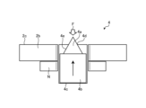
- a laser processing head having an optical path hole formed therein for passing a laser beam and extending in a first direction. , a first machining head, and a second machining head arranged side by side with the first machining head in a first direction and detachably connected to the first machining head. ing.
- a first inclined surface that is inclined with respect to the first direction is formed at an end portion of the first machining head facing the second machining head.
- a second slanted surface parallel to the first slanted surface is formed at the end of the second machining head facing the first machining head.
- At least one of the first inclined surface and the second inclined surface is provided with an adsorption member that detachably connects the first machining head portion and the second machining head portion. At least one of the first inclined surface and the second inclined surface is provided with a positioning pin projecting toward the other. At least the other of the first inclined surface and the second inclined surface is provided with a positioning recess into which the positioning pin is inserted. The number of each of the positioning pins and positioning recesses is plural.
- the laser processing head according to the present disclosure has the effect of increasing the positioning accuracy when connecting the first processing head portion and the second processing head portion.
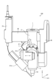
- FIG. 1 is a diagram showing a schematic configuration of an additive manufacturing apparatus according to a first embodiment
- FIG. 1 is a perspective view showing a laser processing head, a wire feeder, a wire straightener, and a height sensor according to Embodiment 1
- FIG. FIG. 2 is a perspective view showing the laser processing head in Embodiment 1, showing a state in which the first processing head and the second processing head are connected
- FIG. 2 is a perspective view showing the laser processing head according to Embodiment 1, showing a state in which the first processing head section and the second processing head section are separated
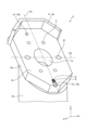
- FIG. 4 is a perspective view showing an end of the first machining head facing the second machining head
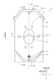
- a plan view showing an end portion of the first machining head facing toward the second machining head A plan view showing an end portion of the second processing head portion facing the first processing head portion.
- Sectional view along line IX-IX shown in FIG. Cross-sectional view along line XX shown in FIG.
- Sectional view along line XII-XII shown in FIG. Sectional view along line XIII shown in FIG.
- Perspective view showing a magnet The perspective view which showed the 1st processing head part
- the perspective view which showed the 2nd processing head part FIG.
- FIG. 8 is a cross-sectional view showing the state of the laser processing head at the time of downward collision, corresponding to the cross-sectional view taken along line IX-IX shown in FIG. 7;
- FIG. 8 is a cross-sectional view showing the state of the laser processing head at the time of downward collision, corresponding to the cross-sectional view taken along line XI-XI shown in FIG. 7;
- FIG. 8 is a cross-sectional view showing the state of the laser processing head at the time of collision in the Y-axis direction, and corresponds to the cross-sectional view taken along line IX-IX shown in FIG. 7;
- FIG. 11 is a cross-sectional view showing a fixing pin and a pin groove of a laser processing head according to Modification 5 of Embodiment 1;
- FIG. 11 is a cross-sectional view showing a fixing pin and a pin groove of a laser processing head according to Modification 6 of Embodiment 1;
- FIG. 11 is a cross-sectional view showing a fixing pin and a pin groove of a laser processing head according to Modification 7 of Embodiment 1;
- FIG. 11 is a cross-sectional view showing a fixing pin and a pin groove of a laser processing head according to Modification 8 of Embodiment 1;
- FIG. 11 is a cross-sectional view showing a fixing pin and a pin groove of a laser processing head according to Modification 9 of Embodiment 1;
- FIG. 11 is a cross-sectional view showing a fixing pin and a pin groove of a laser processing head according to Modification 10 of Embodiment 1;
- FIG. 11 is a cross-sectional view showing a fixing pin and a pin groove of a laser processing head according to Modification 11 of Embodiment 1;
- the perspective view which showed the edge part which turns to the 2nd processing head part among the 1st processing head parts of the laser processing head concerning the modification 12 of Embodiment 1.
- the perspective view showing the end portion facing the first processing head portion of the second processing head portion of the laser processing head according to Modification Example 12 of Embodiment 1.
- FIG. 8 is a cross-sectional view showing a laser processing head according to Modification Example 13 of Embodiment 1, which corresponds to a cross-sectional view taken along line IX-IX shown in FIG. 7;
- FIG. 21 is a diagram schematically showing a movable pin of a laser processing head according to Modification 17 of Embodiment 1;
- FIG. 14 is a diagram schematically showing a movable pin of a laser processing head according to Modification 18 of Embodiment 1;
- FIG. 11 is a diagram schematically showing a pin seat of a laser processing head according to Modification 20 of Embodiment 1; Explanatory drawing for explaining the point of contact between the movable pin and the pin seat FIG. 49 is an explanatory diagram for explaining the contact between the movable pin and the pin seat, showing a case where the position of the contact is different from that in FIG. 48; A plan view showing an end portion of the first processing head portion of the laser processing head according to Modification 21 of Embodiment 1, which faces toward the second processing head portion. A plan view showing an end portion of the first processing head portion of the laser processing head according to Modification Example 22 of Embodiment 1, which faces toward the second processing head portion.
- a plan view showing an end portion facing toward the second processing head portion of the first processing head portion of the laser processing head according to Modification Example 25 of Embodiment 1 A plan view showing an end portion of the first processing head portion of the laser processing head according to Modification Example 26 of Embodiment 1, which faces toward the second processing head portion.
- FIG. 14 is a perspective view showing a magnet of a laser processing head according to Modification 29 of Embodiment 1; Sectional view showing a state in which the magnet shown in FIG. 58 is arranged in the first processing head section The perspective view which showed the edge part which turns to the 2nd processing head part among the 1st processing head parts of the laser processing head concerning the modification 30 of Embodiment 1.
- FIG. 12 is a perspective view showing a second processing head portion of a laser processing head according to Modification 31 of Embodiment 1;
- FIG. 12 is a perspective view showing a magnet and a yoke of a laser processing head according to Modification 32 of Embodiment 1;
- FIG. 11 is a perspective view showing an end portion of the first processing head portion of the laser processing head according to Modification Example 33 of Embodiment 1, which faces toward the second processing head portion;
- FIG. 14 is a perspective view showing a magnet and a yoke of a laser processing head according to Modification 34 of Embodiment 1;
- FIG. 14 is a perspective view showing a magnet and a yoke of a laser processing head according to Modification 35 of Embodiment 1;
- FIG. 14 is a perspective view showing a magnet and a yoke of a laser processing head according to Modification 36 of Embodiment 1;
- FIG. 21 is a perspective view showing a magnet and a yoke of a laser processing head according to Modification 37 of Embodiment 1;
- FIG. 14 is a perspective view showing a magnet and a yoke according to Modification 38 of Embodiment 1;
- FIG. 1 is a diagram showing a schematic configuration of an additive manufacturing apparatus 100 according to Embodiment 1.
- the additive manufacturing apparatus 100 is a machine tool that manufactures a modeled object by layering melted materials.
- the additive manufacturing apparatus 100 performs additive manufacturing using arc welding and beam irradiation.
- the term "modeled object" includes not only a finished product obtained by laminating molten materials, but also materials laminated during the manufacture of a finished product.
- the additive manufacturing apparatus 100 feeds the material wire 33 and laminates a bead made of the melted material on the base material 28 .
- the additive manufacturing apparatus 100 forms the modeled object 29 on the base material 28 by laminating beads on the base material 28 .
- a substrate 28 is placed on a stage 30 .
- a workpiece is an object to which molten material is applied, and here refers to the base material 28 and the modeled object 29 .
- the substrate 28 shown in FIG. 1 is a plate material, it may be other than the plate material.
- the additive manufacturing apparatus 100 includes a laser oscillator 20, a laser processing head 1, a feeding mechanism 21, a CMT (Cold Metal Transfer) power supply 22, a gas injection device 23, a driving section 24, a rotating shaft 25, a high It has a sensor 26 and a control device 27 .
- a laser oscillator 20 includes a laser oscillator 20, a laser processing head 1, a feeding mechanism 21, a CMT (Cold Metal Transfer) power supply 22, a gas injection device 23, a driving section 24, a rotating shaft 25, a high It has a sensor 26 and a control device 27 .
- CMT Cold Metal Transfer
- the laser oscillator 20 generates a laser beam 32.
- a laser beam 32 propagates to the laser processing head 1 through a fiber cable 31 that is an optical transmission line.
- the laser processing head 1 irradiates a work with a laser beam 32 generated by a laser oscillator 20 .
- the feeding mechanism 21 feeds the wire 33 to the work.
- the feed mechanism 21 has a wire spool 21a, a rotary motor 21b, a wire straightener 21c, and a wire feeder 21d.
- the wire spool 21a is the supply source of the wire 33. As shown in FIG. A coiled wire 33 is wound around the wire spool 21a.
- the rotary motor 21b rotates the wire spool 21a.
- the wire straightening machine 21c straightens the wire 33 by removing the curl of the wire 33 delivered from the wire spool 21a.
- the wire feeder 21d feeds the wire 33 straightened by the wire straightener 21c to the work.
- the rotary motor 21b performs driving for sending out the wire 33 from the wire spool 21a toward the work and driving for returning the sent-out wire 33 to the wire spool 21a.
- the CMT power supply 22 is a power supply that supplies current to the wire 33 for heating the wire 33 fed to the work.
- CMT power supply 22 is connected to wire feeder 21 d and stage 30 .
- the wire 33 and the CMT power supply 22 are electrically connected by contacting the wire 33 and the wire feeder 21d.
- the workpiece and the CMT power supply 22 are electrically connected by the contact between the substrate 28 and the stage 30 .
- a CMT power supply 22 applies a pulse voltage between the wire 33 and the workpiece.
- the CMT power supply 22 generates an arc by applying a pulse voltage when the wire 33 is separated from the work.
- the CMT power supply 22 controls the current so that the current increases when the short circuit between the wire 33 and the work is released than when the wire 33 and the work are short-circuited. Also, the CMT power supply 22 heats the wire 33 by applying an electric current to the wire 33 .
- the gas injection device 23 injects gas 34 onto the work.
- the gas 34 flows from the gas injection device 23 through the pipe 35 to the laser processing head 1 and is injected from the laser processing head 1 toward the work.
- the additional manufacturing apparatus 100 suppresses oxidation of the modeled article 29 and cools the bead by injecting the gas 34 .
- the drive unit 24 moves the laser processing head 1 and the wire feeder 21d.
- the drive unit 24 is an operating mechanism that performs translational motion in the directions of each of the three axes.
- the drive unit 24 moves the feeding position of the wire 33 on the work and the irradiation position of the laser beam 32 on the work.
- the rotating shaft 25 rotates the stage 30 .
- the additional manufacturing apparatus 100 can make the posture of the work suitable for processing.
- the height sensor 26 is a sensor for detecting the distance in the height direction between the tip of the nozzle 3d and the workpiece during machining. A detection result of the height sensor 26 is sent to the control device 27 .
- the control device 27 controls the entire additional manufacturing device 100 .
- the control device 27 controls the starting and stopping of the driving section 24, the rotating shaft 25, the laser oscillator 20, the rotating motor 21b, the CMT power source 22 and the gas injection device 23, and the like.
- FIG. 2 is a perspective view showing the laser processing head 1, wire feeder 21d, wire straightener 21c, and height sensor 26 in Embodiment 1.
- FIG. 2 when describing the directions of the components of the wire feeder 21d, the wire straightener 21c, and the height sensor 26 of the laser processing head 1, the X-axis, Y-axis, and Z-axis directions shown in FIG. 2 will be followed.
- the X-axis direction, Y-axis direction and Z-axis direction shown in drawings other than FIG. 2 correspond to the X-axis direction, Y-axis direction and Z-axis direction shown in FIG.
- the X-axis direction and the Y-axis direction are horizontal directions.
- the Z-axis direction is the vertical direction.
- the Z-axis direction corresponds to the first direction.
- the direction indicated by the arrow in the figure is sometimes called the plus X direction, and the opposite direction to the plus X direction is sometimes called the minus X direction.
- the direction indicated by the arrow in the figure is sometimes called the plus Y direction, and the opposite direction to the plus Y direction is sometimes called the minus Y direction.
- the direction indicated by the arrow in the figure is sometimes called the plus Z direction
- the opposite direction to the plus Z direction is sometimes called the minus Z direction.
- the plus Z direction is vertically upward.
- the minus Z direction is vertically downward.
- the additional manufacturing apparatus 100 includes a support frame 36 that supports the laser processing head 1, the wire straightener 21c, the height sensor 26, and the like, and a fastening mechanism that fastens the wire feeder 21d and the support frame 36. and a structure 37 .
- the wire straightener 21c is separated from the wire feeder 21d in the Z-axis direction.
- the wire straightener 21c is separated from the height sensor 26 in the X-axis direction.
- the wire straightening machine 21c is disposed on the opposite side of the height sensor 26 in the X-axis direction across an optical path hole 1a of the laser processing head 1, which will be described later.
- the wire feeder 21d is separated from the height sensor 26 in the X-axis direction.
- the wire feeder 21d is fixed to a second processing head section 3 of the laser processing head 1, which will be described later.
- the wire feeder 21d and the second processing head 3 are separated from the first processing head 2, which will be described later.
- the wire feeder 21 d has a position adjusting mechanism 21 e for adjusting the position with respect to the second machining head section 3 .
- the position adjustment mechanism 21e can adjust the position of the wire feeder 21d in the directions of the double arrows shown in FIG. 2, that is, in the X-, Y- and Z-axis directions.
- the fastening structure 37 is a metal wire that connects the position adjustment mechanism 21 e and the support frame 36 . Even when the wire feeder 21d collides with the work and comes off the second processing head section 3 of the laser processing head 1, the fastening structure 37 for fastening the wire feeder 21d and the support frame 36 is provided. By avoiding collision of the detached wire feeder 21d with the laser processing head 1 and the like, damage to the wire feeder 21d, the laser processing head 1 and the like can be suppressed.
- the second processing head section 3 slides in the arrow Y direction in FIG.
- the wire feeder 21d is arranged on the opposite side of the height sensor 26 in the X-axis direction with the optical path hole 1a of the laser processing head 1 interposed therebetween. As a result, it is possible to prevent the wire feeder 21d that slides together with the second machining head section 3 from colliding with the height sensor 26, thereby suppressing damage to the wire feeder 21d and the height sensor 26. can.
- the wire straightener 21c and the height sensor 26 are arranged in a direction orthogonal to the sliding movement direction of the second processing head section 3. That is, the wire straightening machine 21c and the height sensor 26 are not arranged at the slide movement destination of the second processing head section 3 . As a result, the slid second processing head portion 3 is prevented from colliding with the wire straightener 21c and the height sensor 26, and the second processing head portion 3, the wire straightener 21c and the height sensor 26 are prevented from colliding with each other. Damage can be suppressed.
- the wire straightener 21c and the height sensor 26 are arranged on the same XY plane. Thereby, space saving in the Y-axis direction of the additional manufacturing apparatus 100 can be achieved.
- FIG. 3 is a perspective view showing the laser processing head 1 according to Embodiment 1, showing a state in which the first processing head section 2 and the second processing head section 3 are connected.
- FIG. 4 is a perspective view showing the laser processing head 1 according to Embodiment 1, showing a state in which the first processing head section 2 and the second processing head section 3 are separated.
- the laser processing head 1 has an optical path hole 1a for passing a laser beam 32 therein and extends in the Z-axis direction.
- the laser processing head 1 is movable in each of the X-axis direction, Y-axis direction, and Z-axis direction.
- gas from the gas injection device 23 flows into the optical path hole 1a.
- the laser processing head 1 includes a first processing head unit 2 and a second processing unit that is arranged side by side with the first processing head unit 2 in the Z-axis direction and is detachably connected to the first processing head unit 2.
- a head portion 3 is provided.
- the second machining head portion 3 is arranged vertically below the first machining head portion 2 .
- the first processing head portion 2 is a portion fixed to the driving portion 24 shown in FIG.
- the second processing head portion 3 is a portion that irradiates the work with the laser beam 32, and is a portion that separates from the first processing head portion 2 when the laser processing head 1 collides with the work.
- the first machining head portion 2 includes a first main body portion 2a extending in the Z-axis direction and an end portion of the first main body portion 2a facing the second machining head portion 3. and a first plate portion 2b having a first inclined surface 2c attached thereto.
- the shape of the first main body portion 2a may be cylindrical, but in this embodiment, it is cylindrical.
- the first body portion 2a is made of metal. Metals are, for example, aluminum and stainless steel.
- the first plate portion 2b constitutes an end portion of the first processing head portion 2 facing the second processing head portion 3.
- the first plate portion 2b is made of a non-magnetic material.
- Non-magnetic materials are, for example, aluminum and stainless steel.
- the second machining head portion 3 is attached to a second main body portion 3a extending in the Z-axis direction, and an end portion of the second main body portion 3a facing the first machining head portion 2 to form a second machining head portion. and a second plate portion 3b having an inclined surface 3c.
- the shape of the second body portion 3a may be cylindrical, but in this embodiment, it is cylindrical.
- the second body portion 3a is made of metal.
- the metal is, for example, plated iron.
- a nozzle 3d for irradiating a work with a laser beam 32 is attached to the end of the second main body 3a facing away from the first processing head 2. As shown in FIG.
- the nozzle 3d is made of metal such as copper.
- a cooling water joint 3e is attached to the outer peripheral surface of the second body portion 3a.
- a pipe through which cooling water flows is connected to the cooling water coupling 3 e , and a cooling channel through which the cooling water flows is formed inside the second processing head section 3 .
- the cooling flow path communicates with the pipe via the cooling water joint 3e.
- the second plate portion 3b constitutes an end portion of the second processing head portion 3 facing the first processing head portion 2.
- the second plate portion 3b is made of a magnetic material.
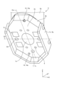
- FIG. 5 is a perspective view showing an end portion of the first machining head portion 2 facing the second machining head portion 3.
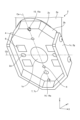
- FIG. FIG. 6 is a perspective view showing an end of the second machining head 3 facing the first machining head 2.
- the shape of the first plate portion 2b shown in FIG. 5 and the shape of the second plate portion 3b shown in FIG. 6 are octagonal in the present embodiment, but may be changed as appropriate.
- the first plate portion 2b is formed with a first inclined surface 2c inclined with respect to the Z-axis direction.
- a fixed pin 14, a pin groove 15, a plurality of movable pins 4, a plurality of magnets 6, and a contact sensor 7 are provided on the first inclined surface 2c.
- An optical path hole 1a is opened at the center of the first inclined surface 2c.
- the second plate portion 3b is formed with a second inclined surface 3c parallel to the first inclined surface 2c.
- "Parallel" in the specification of the present application includes not only a completely parallel state but also a slightly inclined state, not strictly parallel.
- the first inclined surface 2c and the second inclined surface 3c are inclined at the same angle in the same direction.
- a fixing pin 14, a pin groove 15, a pin seat 5, a sensor groove 8, and a sensor contact pin 9 are provided on the second inclined surface 3c.
- An optical path hole 1a is opened at the center of the second inclined surface 3c.
- the extension direction of the pin groove 15 is parallel to the tilt direction.
- the tilt direction is the second direction.
- the former is referred to as the first fixing pin 14a
- the latter is referred to as the second fixing pin 14b. called.
- the former is called the first pin groove 15a
- the latter is called the second pin groove 15b. called.
- the first fixing pin 14a shown in FIG. 5 serves as a positioning pin protruding toward the second inclined surface 3c.
- the first fixing pin 14a is immovably fixed to the first plate portion 2b.
- the first fixing pin 14a is inserted into the second pin groove 15b shown in FIG.
- the first fixing pin 14a is provided below the portion of the first inclined surface 2c where the optical path hole 1a is opened in the inclined direction.
- the first pin groove 15a serves as a positioning recess into which the second fixing pin 14b shown in FIG. 6 is inserted.
- the first pin groove 15a extends along the direction of inclination.
- the first pin groove 15a is provided above the portion of the first inclined surface 2c where the optical path hole 1a is opened in the direction of inclination.
- the first pin groove 15a is separated from the portion of the first inclined surface 2c where the optical path hole 1a is opened. That is, the first pin groove 15a and the optical path hole 1a are not connected to each other.
- the first pin groove 15a is cut out to the upper edge of the first inclined surface 2c.
- the magnet 6 serves as an attraction member that detachably connects the first processing head portion 2 and the second processing head portion 3 .
- a neodymium magnet for example, is used for the magnet 6 .
- the movable pin 4 serves as a positioning pin that protrudes toward the second inclined surface 3c shown in FIG. 6 and is biased toward the second inclined surface 3c.
- the movable pin 4 can be inserted into the pin seat 5 shown in FIG. 6 and can be removed from the pin seat 5 .
- the movable pin 4 fits into the pin seat 5 when inserted into the pin seat 5 .
- the movable pin 4 is arranged independently at a position apart from the fixed pin 14 and the magnet 6 .
- the contact sensor 7 has a contact portion 7c that contacts the sensor contact pin 9 shown in FIG. It is a mechanical sensor that detects When the position of the second machining head portion 3 relative to the first machining head portion 2 is not deviated, the contact-type sensor 7 contacts the sensor contact pin 9 with the contact portion 7c so that the control device 27 shown in FIG. is configured to transmit an ON signal to . On the other hand, the contact sensor 7 transmits an OFF signal to the control device 27 when the contact portion 7c moves away from the sensor contact pin 9 when the position of the second processing head portion 3 is displaced with respect to the first processing head portion 2. configured to be Upon receiving the OFF signal, the controller 27 urgently stops the movement of the laser processing head 1 and the irradiation of the laser beam 32 .
- the second fixing pin 14b shown in FIG. 6 serves as a positioning pin protruding toward the first inclined surface 2c.
- the second fixed pin 14b is immovably fixed to the second inclined surface 3c.
- the second fixing pin 14b is inserted into the first pin groove 15a shown in FIG.
- the second fixing pin 14b is provided above the portion of the second inclined surface 3c where the optical path hole 1a is opened in the direction of inclination.
- the second pin groove 15b serves as a positioning recess into which the first fixing pin 14a shown in FIG. 5 is inserted.
- the second pin groove 15b extends along the direction of inclination.
- the second pin groove 15b is provided below the portion of the second inclined surface 3c where the optical path hole 1a is opened in the direction of inclination.
- the second pin groove 15b is separated from the portion of the second inclined surface 3c where the optical path hole 1a is opened. That is, the second pin groove 15b and the optical path hole 1a are not connected to each other.
- the second pin groove 15b is cut out to the lower edge of the second inclined surface 3c.
- the pin seat 5 serves as a positioning recess into which the movable pin 4 shown in FIG. 5 is inserted.
- the pin seat 5 does not have play that allows the movable pin 4 inserted into the pin seat 5 to move along the direction of inclination.
- the sensor groove 8 is a groove that accommodates the sensor contact pin 9 .
- the sensor groove 8 is formed integrally with the second pin groove 15b in this embodiment, it may be formed separately from the second pin groove 15b. That is, the sensor groove 8 may be formed independently so as not to connect with the second pin groove 15b. Even when the sensor grooves 8 are formed independently, the sensor grooves 8 preferably extend along the direction of inclination. In other words, the extension direction of the sensor groove 8 is preferably parallel to the inclination direction.
- the shape of the sensor groove 8 is such that it can accommodate the sensor contact pin 9 and does not interfere with the relative movement with the contact sensor 7 when the second processing head 3 slides. , is not particularly limited.
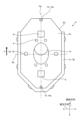
- FIG. 7 is a plan view showing an end portion of the first machining head portion 2 facing the second machining head portion 3.
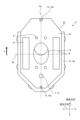
- FIG. FIG. 8 is a plan view showing an end of the second machining head 3 facing the first machining head 2.
- an imaginary straight line passing through the center of the first inclined surface 2c and the second inclined surface 3c along the direction of inclination is defined as a first center line Ca
- An imaginary straight line extending in a direction perpendicular to the first center line Ca passing through is defined as a second center line Cb.
- the direction orthogonal to the inclination direction in the in-plane direction of the first inclined surface 2c and the second inclined surface 3c is referred to as the orthogonal direction.
- the number of fixing pins 14 is two in this embodiment.
- the total number of fixed pins 14 and movable pins 4 should be two or more, and the number of fixed pins 14 may be singular or plural. If the total number of the fixed pin 14 and the movable pin 4, which are positioning pins, is at least two, the second machining head portion 3 when the first machining head portion 2 and the second machining head portion 3 are connected. rotation can be suppressed. If the movable pin 4 is omitted, the number of fixed pins 14 should be at least two.
- the first fixing pin 14a and the first pin groove 15a are arranged on the same straight line along the tilt direction.
- the first fixing pin 14a and the first pin groove 15a are arranged on the first center line Ca in the present embodiment.
- the second fixing pin 14b and the second pin groove 15b are arranged on the same straight line along the tilt direction.
- the second fixing pin 14b and the second pin groove 15b are arranged on the first center line Ca in the present embodiment.
- the plurality of fixing pins 14 and the plurality of pin grooves 15 are arranged on the same straight line along the direction of inclination in this embodiment.
- the contact sensor 7 and the sensor contact pin 9 are arranged on the same straight line along the direction of inclination as the plurality of fixing pins 14 and the plurality of pin grooves 15 in this embodiment.
- the number of movable pins 4 shown in FIG. 7 may be singular or plural, but is four in the present embodiment.
- the four movable pins 4 are spaced apart from each other in the oblique and orthogonal directions.
- the movable pins 4 are arranged one by one in four regions defined by the first center line Ca and the second center line Cb.
- the two movable pins 4 arranged above in the tilt direction across the second center line Cb are aligned in the tilt direction.
- the two movable pins 4 arranged below in the tilt direction across the second center line Cb are aligned in the tilt direction.
- the two movable pins 4 arranged on one side in the orthogonal direction across the first center line Ca are aligned in the orthogonal direction.
- the two movable pins 4 arranged in the other orthogonal direction across the first center line Ca are aligned in the orthogonal direction.
- the movable pin 4 is arranged at a position farther from the first center line Ca and closer to the second center line Cb than the first fixing pin 14a and the first pin groove 15a. .
- the movable pin 4 and the magnet 6 are provided on the same first plate portion 2b in this embodiment. That is, the movable pin 4 and the magnet 6 are arranged only on the first inclined surface 2c in this embodiment. Therefore, when the second machining head portion 3 slides, contact between the movable pin 4 and the magnet 6 can be avoided, and damage to the magnet 6 can be suppressed.
- the number of pin seats 5 shown in FIG. 8 should be the same as the number of movable pins 4, which is four in the present embodiment.
- the pin seats 5 are spaced apart from each other in the oblique direction and the orthogonal direction.
- One pin seat 5 is arranged in each of four regions defined by the first center line Ca and the second center line Cb.
- the arrangement intervals of the four pin seats 5 are the same as the arrangement intervals of the four movable pins 4 .
- the pin seat 5 is arranged at a position farther from the first center line Ca and closer to the second center line Cb than the second fixing pin 14b and the second pin groove 15b. .
- the number of magnets 6 shown in FIG. 7 is preferably two or more, but four in this embodiment.
- the four magnets 6 are spaced from each other in oblique and orthogonal directions.
- the magnets 6 are arranged one by one in four regions defined by the first centerline Ca and the second centerline Cb.
- the two magnets 6 arranged above in the tilt direction across the second center line Cb are aligned in the tilt direction.
- the two magnets 6 arranged below in the tilt direction across the second center line Cb are aligned in the tilt direction.
- the two magnets 6 arranged in one of the orthogonal directions across the first center line Ca are aligned in the orthogonal direction.
- the two magnets 6 arranged on the other side in the orthogonal direction across the first center line Ca are aligned in the orthogonal direction.
- the magnet 6 is arranged at a position farther from the first center line Ca and closer to the second center line Cb than the first fixed pin 14a, the first pin groove 15a and the movable pin 4. It is The magnet 6 is arranged at a position avoiding the fixed pin 14, the movable pin 4 and the contact sensor 7 on the first inclined surface 2c. In addition, the magnet 6 holds the fixing pin 14 and the sensor contact pin 9 of the second inclined surface 3c shown in FIG. placed in a avoidance position. Furthermore, the magnet 6, the fixing pin 14, and the sensor contact pin 9 are arranged at positions out of the same straight line along the tilt direction. As a result, when the second machining head portion 3 slides relative to the first machining head portion 2, the magnet 6 is prevented from coming into contact with the fixed pin 14 and the sensor contact pin 9. Damage can be suppressed.
- a first insertion hole 2d for inserting a fastening member 10 that fastens the first plate portion 2b and the first body portion 2a is opened in the first inclined surface 2c.
- a second insertion hole 3f for inserting a fastening member 11 that fastens the second plate portion 3b and the second body portion 3a is opened in the second inclined surface 3c. ing.
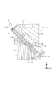
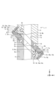
- FIG. 9 is a cross-sectional view taken along line IX-IX shown in FIG.
- FIG. 10 is a cross-sectional view taken along line XX shown in FIG. 9 and 10 also show a cross section of the second processing head portion 3.
- the contact sensor 7 is a rod-shaped member. The contact sensor 7 is attached through the first plate portion 2b. The tip of the contact sensor 7 is exposed from the first inclined surface 2c. The contact sensor 7 provided on the first inclined surface 2c is inclined to form an acute angle with the first inclined surface 2c. The angle ⁇ 1 formed between the contact sensor 7 and the first inclined surface 2c is an acute angle. The contact sensor 7 is attached to the first plate portion 2b so that the tip of the contact sensor 7 is tilted upward in the tilt direction.
- the length dimension along the inclination direction of the first pin groove 15a is larger than the thickness dimension of the second fixing pin 14b.
- the length dimension along the inclination direction of the second pin groove 15b is larger than the thickness dimension of the first fixing pin 14a.
- the inner wall of the first pin groove 15a has a restricting surface 15d located below the second fixing pin 14b in the direction of inclination. 15 d of control surfaces play the role which contacts the 2nd fixing pin 14b, and controls the movement of the downward direction of the inclination direction of the 2nd processing head part 3. As shown in FIG.
- the first machining head portion 2 is provided with a plurality of pins 12 for positioning the first body portion 2a and the first plate portion 2b. Further, the second processing head portion 3 is provided with a plurality of pins 13 for positioning the second body portion 3a and the second plate portion 3b.
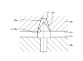
- a fixing pin side contact surface 14 c that tapers toward the pin groove 15 is formed at the tip of the fixing pin 14 .
- the fixed-pin-side contact surface 14c is formed in a hemispherical shape whose diameter decreases from the root side of the fixed pin 14 toward the tip side thereof.
- the pin groove 15 is formed with a pair of pin groove side contact surfaces 15c with which the fixed pin side contact surface 14c contacts.
- the pair of pin groove side contact surfaces 15c are formed in a V shape that widens in the groove width direction from the groove bottom of the pin groove 15 toward the opening.
- the pair of pin groove side contact surfaces 15c are symmetrical in the groove width direction.
- the groove width direction coincides with the X-axis direction.
- the pin groove side contact surface 15c contacts the fixing pin 14 and functions to regulate the movement of the second machining head portion 3 along the X-axis direction.
- FIG. 11 is a cross-sectional view along line XI-XI shown in FIG.
- FIG. 12 is a cross-sectional view taken along line XII-XII shown in FIG.
- FIG. 13 is a diagram schematically showing the movable pin 4.
- FIG. 11 also shows a cross section of the second processing head section 3 .
- FIG. 12 also shows a cross section of the first processing head section 2 .
- the fastening member 11 is screwed into the second plate portion 3b and the second body portion 3a.
- the fastening member 11 is, for example, a bolt.
- the movable pin 4 has a movable part 4a, biasing means 4b, and a container 4c.
- the container 4c is a cylindrical member with a bottom.
- the container 4c is formed with an opening 4d through which the movable part 4a protrudes.
- the movable part 4a is a member movable in a direction of protruding from the opening 4d of the container 4c and a direction of being pushed into the bottom of the container 4c.
- a movable pin-side contact surface 4e that tapers toward the pin seat 5 is formed at the tip of the movable part 4a.
- the movable-pin-side contact surface 4e is formed in a hemispherical shape whose diameter decreases from the root side toward the tip side of the movable part 4a.
- the biasing means 4b is disposed between the movable part 4a and the bottom of the container 4c and serves to bias the movable part 4a in the direction of protruding from the opening 4d of the container 4c.
- the biasing means 4b is, for example, an elastic body, air, or oil.
- Elastic bodies are, for example, springs and rubbers.
- the movable pin 4 is a push-type movable pin that pushes out the movable part 4a in the direction of protruding from the opening 4d of the container 4c.
- the movable part 4a is pushed toward the bottom of the container 4c.
- the movable part 4a is pushed out toward the opening 4d of the container 4c by the biasing force of the biasing means 4b. returns to its original shape.
- a thread groove (not shown) is cut on the outer peripheral surface of the container 4c.
- a nut N is welded to the rear surface of the first plate portion 2b.
- the fixing method of the movable pin 4 may be, for example, a fixing method such as adhesion or press-fitting.
- the shape of the pin seat 5 shown in FIG. 11 is cylindrical in this embodiment.
- the inner surface of the pin seat 5 is formed with a pin seat side contact surface 5a with which the movable pin side contact surface 4e contacts.
- the pin-seat-side contact surface 5a contacts the movable pin 4 and functions to regulate the movement of the second machining head portion 3 along the X-axis direction and downward movement in the tilt direction.
- FIG. 14 is a cross-sectional view along line XIV-XIV shown in FIG.
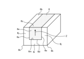
- FIG. 15 is a perspective view showing the magnet 6.
- FIG. FIG. 14 also shows a cross section of the second processing head section 3 .
- the shape of the magnet 6 is plate-like.
- the magnet 6 is magnetized in the thickness direction of the magnet 6 .
- the magnet 6 is formed with a screw hole 6a penetrating in the plate thickness direction of the magnet 6 .
- a screw S is inserted through the screw hole 6a.
- the magnet 6 is arranged in a mounting hole 2e that opens to the first inclined surface 2c.
- the plate thickness dimension of the magnet 6 is smaller than the depth dimension of the mounting hole 2e.
- the magnet 6 is attached to the first plate portion 2b by screwing the screw S into the screw hole 6a of the magnet 6 and the screw hole 2f of the first plate portion 2b.
- Fixed. Magnet 6 is arranged such that the plate thickness direction of magnet 6 is perpendicular to first inclined surface 2c and second inclined surface 3c. A surface of the magnet 6 that faces the second inclined surface 3 c serves as an attraction surface that attracts the second machining head portion 3 .
- the magnet 6 is located on the side farther from the second inclined surface 3c facing the mounting hole 2e than the opening of the mounting hole 2e. That is, the attraction surface of the magnet 6 does not protrude from the opening of the mounting hole 2e and is not flush with the first inclined surface 2c. As a result, the magnet 6 can be prevented from coming into contact with other components, and damage to the magnet 6 can be suppressed. If the arrangement is adjusted so that the magnet 6 and other parts are less likely to come into contact with each other, the attracting surface of the magnet 6 may protrude from the opening of the mounting hole 2e, or the attracting surface of the magnet 6 and the first inclined surface 2c may be separated from each other. may be flush with each other.
- the fastening member 10 is screwed into the first plate portion 2b and the first body portion 2a.
- the fastening member 10 is, for example, a bolt.
- the first plate portion 2b protrudes from the first main body portion 2a in a direction crossing the Z-axis direction.
- the second plate portion 3b protrudes in a direction crossing the Z-axis direction more than the second main body portion 3a.
- a flange 1b projecting in a direction intersecting the Z-axis direction is formed in the divided portion of the laser processing head 1 between the first processing head portion 2 and the second processing head portion 3.
- the angle of inclination of the flange 1b with respect to the horizontal direction is less than 20 degrees, a strong impact force acts between the first processing head portion 2 and the second processing head portion 3 when the laser processing head 1 collides downward, There is a possibility that the first machining head portion 2 and the second machining head portion 3 are easily damaged.
- the angle of inclination of the flange 1b with respect to the horizontal direction exceeds 70 degrees, it is necessary for the second processing head portion 3 to separate from the first processing head portion 2 when the laser processing head 1 collides in the +Y direction. force increases, and the first machining head portion 2 and the second machining head portion 3 may be easily damaged.
- the inclination angle of the flange 1b with respect to the horizontal direction is preferably 20 degrees or more and 70 degrees or less.
- the inclination angle of the flange 1b with respect to the horizontal direction is more preferably 40 degrees or more and 50 degrees or less.
- FIG. 16 is a perspective view showing the first processing head section 2.
- FIG. FIG. 17 is a perspective view showing the second processing head section 3.
- the first inclined surface 2c shown in FIG. 16 and the second inclined surface 3c shown in FIG. 17 have the same external shape and the same outer peripheral dimensions.
- the laser processing head 1 includes a cover 1c surrounding the first inclined surface 2c and the second inclined surface 3c. Rubber, for example, is used as the material of the cover 1c.
- the cover 1c has a first cover 2g attached to the first plate portion 2b shown in FIG. 16 and a second cover 3g attached to the second plate portion 3b shown in FIG. ing.
- the first cover 2g is provided along the lower edge and side edge of the first inclined surface 2c.
- the first cover 2g is provided along the lower five sides in the inclination direction among the eight sides of the first inclined surface 2c.
- the second cover 3g is provided along the upper edge of the second inclined surface 3c.
- the second cover 3g is provided along the upper three sides in the direction of inclination among the eight sides of the second inclined surface 3c.
- FIG. 18 is a cross-sectional view showing the state of the laser processing head 1 at the time of downward collision, and corresponds to the cross-sectional view taken along line IX-IX shown in FIG.
- FIG. 19 is a cross-sectional view showing the state of the laser processing head 1 at the time of downward collision, and corresponds to the cross-sectional view taken along line XI-XI shown in FIG.
- FIG. 20 is a cross-sectional view showing the state of the laser processing head 1 when it collides in the Y-axis direction, and corresponds to the cross-sectional view taken along line IX-IX shown in FIG.
- FIG. 21 is a perspective view showing the state when the laser processing head 1 collides in the X-axis direction. An arrow Y shown in FIGS. 18 to 21 indicates the moving direction of the second machining head section 3 at the time of collision.
- the downward movement of the second machining head 3 in the tilting direction is restricted by the contact of the second fixing pin 14b with the restricting surface 15d of the first pin groove 15a.
- the contact sensor 7 is in contact with the sensor contact pin 9 .
- the movable pin 4 is pushed out toward the second inclined surface 3c and fitted into the pin seat 5, thereby moving the second machining head 3 in the X-axis direction and downward in the inclination direction. movement is restricted.
- the second processing head portion 3 collides with the work, and an impact force exceeding the attraction force of the magnet 6 is applied to the second processing head portion 3. Then, as shown in FIG. 18, the second machining head portion 3 slides upward in the tilt direction. At this time, since the length dimension along the inclination direction of the second pin groove 15b is larger than the thickness dimension of the first fixing pin 14a, the second pin groove 15b trying to move upward in the inclination direction The sliding movement of the second processing head portion 3 is not hindered by the relative movement of the first fixing pin 14a along the second pin groove 15b. Since the second pin groove 15b is cut out to the lower edge of the second inclined surface 3c, the first fixing pin 14a is easily removed from the second pin groove 15b, and the second machining head portion 3 is It becomes easy to separate from the first processing head unit 2 .
- the second fixing pin 14b extends along the first pin groove 15a to the first pin groove 15a.
- the sliding movement of the second machining head portion 3 is not hindered. Since the first pin groove 15a is cut out to the upper edge of the first inclined surface 2c, the second fixing pin 14b is easily removed from the first pin groove 15a, and the second machining head portion 3 is It becomes easy to separate from the first processing head unit 2 .
- the movable part 4a separates from the pin seat 5 when the second machining head 3 slides, so that the sliding movement of the second machining head 3 is not hindered.
- the horizontal collision which is the case where the laser processing head 1 collides with the work while moving in the Y-axis direction
- the second processing head portion 3 collides with the work while the laser processing head 1 is moving in the +Y direction of the Y-axis
- an impact force exceeding the attraction force of the magnet 6 is applied to the second processing head portion 3.
- the second machining head 3 rotates in the direction of action of the impact force and separates from the first machining head 2 .
- the first fixing pin 14a is removed from the second pin groove 15b, the rotation of the second machining head portion 3 is not hindered.
- the second fixing pin 14b is removed from the first pin groove 15a, so that the rotation of the second machining head portion 3 is not hindered.
- the movement of the second machining head 3 is not hindered by the movable part 4a being separated from the pin seat 5.
- the laser processing head 1 is moving in the negative Y direction of the Y axis, the second processing head 3 collides with the work, and an impact force exceeding the attraction force of the magnet 6 is applied to the second processing head 3 .
- the operation is the same as in the case where the laser processing head 1 collides with the workpiece while moving in the +Y direction of the Y axis.
- the laser processing head 1 shown in FIG. Even if an impact force exceeding the attracting force of the magnet 6 is applied to the second processing head portion 3 by colliding with the work, the laser processing head 1 collides with the work while moving in the +Y direction of the Y-axis. It works the same as if
- the magnet 6 that detachably connects the first machining head portion 2 and the second machining head portion 3 is provided on the first inclined surface 2c. is provided.
- the first machining head portion 2 and the second machining head Part 3 is separated.
- the second processing head portion 3 collides with the work while the laser processing head 1 is moving downward in the vertical direction, the second processing head portion 3 slides upward in the tilt direction and moves to the first position. Move away from the processing head section 2 .
- the second processing head portion 3 collides with the work while the laser processing head 1 is moving in the horizontal direction, the second processing head portion 3 rotates in the acting direction of the impact force and separates from the first processing head portion 2. . Therefore, an excessive impact force is not applied to the laser processing head 1, and damage to the laser processing head 1 can be prevented.
- the first inclined surface 2c is provided with a fixing pin 14 protruding toward the other side, and the fixing pin 14 is inserted into the second inclined surface 3c.
- a pin groove 15 is provided.
- a fixing pin 14 projecting toward the first inclined surface 2c is provided on the second inclined surface 3c, and a pin groove 15 into which the fixing pin 14 is inserted is provided on the first inclined surface 2c.
- the first processing head portion 2 and the second processing head portion 2 can be reconnected.
- the positional relationship between the first processing head portion 2 and the second processing head portion 3 does not shift before the separation of the head portions 3 and after the reconnection.
- occurrence of optical axis deviation of the laser beam 32 is suppressed before the separation of the first processing head portion 2 and the second processing head portion 3 and after reconnection. can do. Therefore, it is possible to obtain a laser processing machine in which the processing quality does not change between before the separation of the first processing head portion 2 and the second processing head portion 3 and after the reconnection.
- the fixing pin 14 is inserted into the pin groove 15, so that the laser processing head 1 performs operations such as rapid acceleration and sudden stop.
- the second machining head portion 3 can be prevented from being displaced from the first machining head portion 2 .
- the wire feeder 21d is fixed to the second processing head portion 3, and when the first processing head portion 2 and the second processing head portion 3 are connected, Due to the high positioning accuracy, the tip of the wire feeder 21d and the nozzle 3d of the second machining head 3 before the separation of the first machining head 2 and the second machining head 3 and after the reconnection. There is no deviation of the positional relationship with Therefore, it is possible to omit the adjustment work for matching the positions of the tip of the wire feeder 21d and the nozzle 3d of the second processing head portion 3 .
- the length dimension of the pin groove 15 along the direction of inclination is larger than the thickness dimension of the fixing pin 14 .
- the fixing pin 14 is a first fixing pin 14a provided below the portion of the first inclined surface 2c where the optical path hole 1a is opened in the direction of inclination.
- a second fixing pin 14b provided above the portion of the second inclined surface 3c where the optical path hole 1a is opened in the direction of inclination.
- the pin groove 15 includes the first pin groove 15a provided above the portion of the first inclined surface 2c where the optical path hole 1a is opened in the direction of inclination, and the second inclined pin groove 15a. and a second pin groove 15b provided below the portion of the surface 3c where the optical path hole 1a is opened in the direction of inclination.
- the first pin groove 15a is cut out to the upper edge of the first inclined surface 2c, and the second pin groove 15b is formed by cutting the second inclined surface 2c. It is notched up to the lower edge of 3c.
- the first fixing pin 14a is easily pulled out of the second pin groove 15b. Since the second fixing pin 14b is easily removed from the first pin groove 15a, the second machining head portion 3 is easily separated from the first machining head portion 2. As shown in FIG.
- the inner surface of the first pin groove 15a is located below the second fixing pin 14b in the inclination direction, and is positioned in the inclination direction of the second fixing pin 14b. It has a restricting surface 15d that restricts downward movement. As a result, the second fixing pin 14b comes into contact with the regulating surface 15d of the first pin groove 15a, and the downward movement of the second machining head 3 in the tilt direction is regulated.
- the pin groove 15 is separated from the optical path hole 1a.
- the pin groove 15 is provided in a laser processing machine that causes gas to flow through the optical path hole 1a during processing, it is possible to prevent a decrease in gas concentration and turbulence in the gas flow. Therefore, it is possible to prevent deterioration of the machining quality of the workpiece.
- the fixing pin 14 is formed with a fixing pin side contact surface 14c that tapers toward the pin groove 15, and the pin groove 15 has the fixing pin side contact surface 14c.
- a pin groove side contact surface 15c having a symmetrical shape in the groove width direction is formed.
- the plurality of fixing pins 14 are arranged on the same straight line along the direction of inclination, so that each fixing pin 14 is aligned with the first inclined surface 2c. And the attachment property at the time of attachment to the second inclined surface 3c can be improved.
- a movable pin 4 protruding toward the second inclined surface 3c and biased toward the second inclined surface 3c is provided on the first inclined surface 2c.
- a pin seat 5 into which the movable pin 4 is inserted is provided on the second inclined surface 3c.
- the movable pin 4 is inserted into the pin seat 5 .
- the positional relationship between the first machining head portion 2 and the second machining head portion 3 is accurately determined, so the positioning accuracy when connecting the first machining head portion 2 and the second machining head portion 3 is improved. It is possible to obtain a laser processing head 1 with a higher .
- the movable pin 4 is inserted into the pin seat 5, so that the laser processing head 1 performs operations such as rapid acceleration and sudden stop.
- the second machining head portion 3 can be prevented from being displaced from the first machining head portion 2 .
- the fixed pin 14 and the movable pin 4 are arranged at a position avoiding the magnet 6, so that the fixed pin 14 and the movable pin 4 and the magnet 6 are separated from each other. contact can be avoided, and damage to the magnet 6 can be suppressed.
- the movable pin 4 and the magnet 6 are arranged only on the first inclined surface 2c, when the second machining head portion 3 slides, the movable pin 4 and the magnet 6 are displaced. Damage to the magnet 6 can be suppressed by avoiding contact with the magnet 6 .
- the second inclined surface 3c is provided with the sensor contact pin 9, and the first inclined surface 2c is provided with the contact portion 7c that contacts the sensor contact pin 9.
- a contact sensor 7 is provided for detecting the displacement of the second machining head 3 with respect to the first machining head 2 by displacing the contact portion 7c. Accordingly, when the contact sensor 7 detects the displacement of the second processing head 3, the controller 27 shown in FIG. 1 quickly stops the movement of the laser processing head 1 and the irradiation of the laser beam 32. can.
- the contact sensor 7 provided on the first inclined surface 2c is inclined to form an acute angle with the second inclined surface 3c.
- the second inclined surface 3c is provided with a sensor groove 8 for accommodating the sensor contact pin 9, and the sensor groove 8 extends along the inclination direction.
- the sensor groove 8 is formed integrally with the pin groove 15, which saves the trouble of processing the sensor groove 8 and the pin groove 15 separately, and enables laser The productivity of the machining head 1 can be enhanced.
- the first plate portion 2b protrudes from the first main body portion 2a in a direction intersecting the Z-axis direction
- the second plate portion 3b protrudes from the first main body portion 2a. 2 projecting in a direction crossing the Z-axis direction.
- the first plate portion 2b protrudes more than the first main body portion 2a in the direction intersecting the Z-axis direction
- the second plate portion 3b protrudes more than the second main body portion 3a. Projecting in the direction intersecting the Z-axis direction increases the areas of the first inclined surface 2c and the second inclined surface 3c. When the areas of the first inclined surface 2c and the second inclined surface 3c are increased, the action distance of the rotational moment acting on the magnet 6 is increased, so that the rotational moment acting on the magnet 6 can be suppressed.
- the first cover 2g and the second cover 3g are separated from each other. , surrounds the first inclined surface 2c and the second inclined surface 3c. This prevents objects from being caught between the first machining head portion 2 and the second machining head portion 3 .
- the first cover 2g is not provided on the upper edge of the first processing head portion 2, when the laser processing head 1 collides downward, the second processing head portion 3 can prevent interference between the second processing head portion 3 and the first cover 2g when the slides upward in the tilt direction. Therefore, even when the first cover 2g and the second cover 3g are provided, the movement of the second machining head portion 3 is not hindered.
- Embodiment 1 Next, a modification of Embodiment 1 will be described.
- the fixed pin 14 as the positioning pin and the movable pin 4 are provided on the first inclined surface 2c, and the fixed pin 14 as the positioning pin is provided on the second inclined surface 2c.
- the fixed pin 14 and the movable pin 4 may be provided on at least one of the first inclined surface 2c and the second inclined surface 3c.
- the pin groove 15 and the pin seat 5, which are positioning recesses may be provided on at least the other of the first inclined surface 2c and the second inclined surface 3c.
- the number of fixed pins 14, movable pins 4, pin grooves 15, and pin seats 5 is not limited to the illustrated example, and may be changed as appropriate.
- one fixed pin 14 and one movable pin 4 may be provided, and one pin groove 15 and one pin seat 5 may be provided. Even with such a configuration, one fixed pin 14 and one movable pin 4 provide a total of two positioning pins. The rotation of the second processing head portion 3 at the time of connection with the can be suppressed.
- the fixed pin 14 and the movable pin 4 are provided as the positioning pins, and the pin groove 15 and the pin seat 5 are provided as the positioning recesses.
- a configuration in which only the pin groove 15 is provided as the recess may be employed. In such a configuration, at least two fixing pins 14 and at least two pin grooves 15 should be provided.
- the pin groove 15 is cut out to the upper edge of the first inclined surface 2c or the lower edge of the second inclined surface 3c. It is not necessary to cut out to the upper edge of the surface 2c or the lower edge of the second inclined surface 3c.
- the pin groove 15 has a sufficient length along the inclination direction so as not to hinder the sliding movement of the second processing head portion 3 when the laser processing head 1 collides downward.
- the depth of the pin groove 15 may be constant over the entire length of the pin groove 15 in the extending direction, but gradually toward the upper edge of the first inclined surface 2c or the lower edge of the second inclined surface 3c. You may make it shallow. With this configuration, the fixing pin 14 is easily removed from the pin groove 15 when the second machining head portion 3 is slid.
- the magnet 6, which is the attracting member, is provided only on the first inclined surface 2c. provided in at least one of them.
- the magnets 6 are provided on both the first inclined surface 2c and the second inclined surface 3c, the portions of the first plate portion 2b and the second plate portion 3b facing the magnets 6 on the other side are not It can be made magnetic.
- the magnet 6 is a component that is easily subject to impact force when the laser processing head 1 collides and is easily damaged. is preferably provided only on the inclined surface 2c.
- the laser processing head 1 has the flange 1b, but the flange 1b may not be provided. That is, the thickness of the laser processing head 1 may be constant over the entire length in the Z-axis direction.
- the first processing head portion 2 is composed of two members, a first main body portion 2a and a first plate portion 2b.
- the first processing head portion 2 may be configured by a single member in which the plate portion 2a and the first plate portion 2b are integrally formed.
- the second processing head portion 3 is composed of two members, the second body portion 3a and the second plate portion 3b.
- the second machining head portion 3 may be composed of a single member integrally formed with the plate portion 3b.
- the laser processing head 1 has a cover 1c, but the cover 1c may not be provided.
- the arrangement of the fixing pins 14 shown in FIGS. 5 and 6 is not limited to the illustrated example, and may be freely changed on the first inclined surface 2c and the second inclined surface 3c.
- the fixing pin 14 and the pin groove 15 may be provided only above the opening of the optical path hole 1a in the inclination direction, or may be provided only below the opening of the optical path hole 1a in the inclination direction. Further, for example, the fixing pin 14 and the pin groove 15 may be spaced apart in the direction orthogonal to the opening of the optical path hole 1a.
- the plurality of fixing pins 14 and the plurality of pin grooves 15 are arranged on the same straight line along the tilt direction. They do not have to be arranged on the same straight line.
- multiple fixing pins 14 and multiple pin grooves 15 may be arranged as shown in FIGS. 22 and 23 .
- 22 is a perspective view showing an end portion of the first processing head portion 2 of the laser processing head 1 according to Modification 1 of Embodiment 1, which faces the second processing head portion 3.
- FIG. 23 is a perspective view showing an end portion of the second processing head portion 3 of the laser processing head 1 according to Modification 1 of Embodiment 1, which faces the first processing head portion 2.
- the fixing pin 14 of the first inclined surface 2c and the pin groove 15 of the second inclined surface 3c are arranged on the first center line Ca.
- the pin groove 15 of the first inclined surface 2c and the fixing pin 14 of the second inclined surface 3c are arranged at positions offset in the orthogonal direction from the first center line Ca.
- the plurality of fixing pins 14 and the plurality of pin grooves 15 may be arranged as shown in FIGS. 24 and 25.
- 24 is a perspective view showing an end portion of the first processing head portion 2 of the laser processing head 1 according to Modification 2 of Embodiment 1, which faces the second processing head portion 3.
- FIG. 25 is a perspective view showing an end portion of the second processing head portion 3 of the laser processing head 1 according to Modification 2 of Embodiment 1, which faces the first processing head portion 2.
- FIG. 24 and 25 are arranged in one of the orthogonal directions across the first center line Ca. is located at a position offset from the center line Ca.
- the pin groove 15 of the first inclined surface 2c and the fixing pin 14 of the second inclined surface 3c are arranged at positions offset from the first center line Ca in the other orthogonal direction across the first center line Ca. It is
- the plurality of fixing pins 14 and the plurality of pin grooves 15 may be arranged as shown in FIGS. 26 and 27.
- 26 is a perspective view showing an end portion of the first processing head portion 2 of the laser processing head 1 according to Modification 3 of Embodiment 1, which faces the second processing head portion 3.
- FIG. 27 is a perspective view showing an end portion of the second processing head portion 3 of the laser processing head 1 according to Modification 3 of Embodiment 1, which faces the first processing head portion 2.
- FIG. 26 is a perspective view showing an end portion of the first processing head portion 2 of the laser processing head 1 according to Modification 3 of Embodiment 1, which faces the first processing head portion 2.
- FIG. 26 is a perspective view showing an end portion of the first processing head portion 2 of the laser processing head 1 according to Modification 3 of Embodiment 1, which faces the first processing head portion 2.
- one fixing pin 14 and two pin grooves 15 are provided on the first inclined surface 2c.
- two fixing pins 14 and one pin groove 15 are provided on the second inclined surface
- the fixing pin 14 of the first inclined surface 2c and the pin groove 15 of the second inclined surface 3c are arranged on the first center line Ca.
- the pin grooves 15 of the first inclined surface 2c are located at positions offset from the first center line Ca in one and the other orthogonal directions with the first center line Ca interposed therebetween. are placed.
- the fixing pins 14 on the second inclined surface 3c are arranged at positions offset from the first center line Ca in one and the other orthogonal directions across the first center line Ca. are placed.
- the plurality of fixing pins 14 and the plurality of pin grooves 15 may be arranged as shown in FIGS. 28 and 29.
- 28 is a perspective view showing an end portion of the first processing head portion 2 of the laser processing head 1 according to Modification 4 of Embodiment 1, which faces the second processing head portion 3.
- FIG. 29 is a perspective view showing an end portion of the second processing head portion 3 of the laser processing head 1 according to Modification 4 of Embodiment 1, which faces the first processing head portion 2.
- two fixing pins 14 and one pin groove 15 are provided on the first inclined surface 2c.
- one fixing pin 14 and two pin grooves 15 are provided on the second inclined surface 3c.
- the pin groove 15 of the first inclined surface 2c and the fixing pin 14 of the second inclined surface 3c are arranged on the first center line Ca.
- the fixing pins 14 on the first inclined surface 2c are arranged at positions offset from the first center line Ca in one and the other orthogonal directions across the first center line Ca. are placed.
- the pin grooves 15 of the second inclined surface 3c are located at positions offset from the first center line Ca in one and the other orthogonal directions with the first center line Ca interposed therebetween. are placed.
- the shape of the fixing pin 14 is not limited to the illustrated example, and may be changed as appropriate.
- the shape of the fixing pin 14 may be a shape as shown in FIG.
- FIG. 30 is a cross-sectional view showing the fixing pin 14 and the pin groove 15 of the laser processing head 1 according to Modification 5 of Embodiment 1.
- a fixed pin side contact surface 14 c that tapers toward the pin groove 15 is formed at the tip of the fixed pin 14 .
- the fixed-pin-side contact surface 14c is formed in a truncated cone shape whose diameter decreases from the base side of the fixed pin 14 toward the tip side thereof.
- the shape of the fixed pin side contact surface 14c may be conical.
- the shape of the pin groove 15 is not limited to the illustrated example, and may be changed as appropriate.
- the pin groove 15 may have a shape as shown in FIGS. 31 and 32.
- FIG. FIG. 31 is a cross-sectional view showing the fixing pin 14 and the pin groove 15 of the laser processing head 1 according to Modification 6 of Embodiment 1.
- FIG. 32 is a cross-sectional view showing the fixing pin 14 and the pin groove 15 of the laser processing head 1 according to Modification 7 of Embodiment 1.
- the pin groove 15 may have a flat groove bottom 15e and may be formed in a V shape that widens in the groove width direction from the groove bottom 15e toward the opening.
- the inner surface of the pin groove 15 is formed with a groove bottom 15e and a pair of pin groove side contact surfaces 15c that widen in the groove width direction from both edges of the groove bottom 15e in the groove width direction toward the opening.
- the pair of pin groove side contact surfaces 15c are symmetrical in the groove width direction.
- the shape of the pin groove 15 may be a shape as shown in FIGS. 33 and 34.
- FIG. 33 is a cross-sectional view showing the fixing pin 14 and the pin groove 15 of the laser processing head 1 according to Modification 8 of Embodiment 1.
- FIG. 34 is a cross-sectional view showing the fixing pin 14 and the pin groove 15 of the laser processing head 1 according to the ninth modification of the first embodiment.
- the pin groove 15 may be formed in a U shape having a flat groove bottom 15e and having a constant groove width from the groove bottom 15e toward the opening.
- the inner surface of the pin groove 15 is formed with a groove bottom 15e and a pair of pin groove side contact surfaces 15c extending linearly from both edges of the groove bottom 15e in the groove width direction toward the opening.
- the pair of pin groove side contact surfaces 15c are symmetrical in the groove width direction.
- the shape of the pin groove 15 may be a shape as shown in FIGS. 35 and 36.
- FIG. 35 is a cross-sectional view showing the fixing pin 14 and the pin groove 15 of the laser processing head 1 according to the tenth modification of the first embodiment.
- 36 is a cross-sectional view showing the fixing pin 14 and the pin groove 15 of the laser processing head 1 according to Modification 11 of Embodiment 1.
- FIG. The pin groove 15 may be formed in an arc shape.
- An arc-shaped pin groove side contact surface 15 c is formed on the inner surface of the pin groove 15 .
- the pin groove side contact surface 15c has a symmetrical shape in the groove width direction.
- FIG. 37 is a perspective view showing an end portion of the first processing head portion 2 of the laser processing head 1 according to Modification 12 of Embodiment 1, which faces the second processing head portion 3.
- FIG. 38 is a perspective view showing an end portion of the second processing head portion 3 of the laser processing head 1 according to Modification 12 of Embodiment 1, which faces the first processing head portion 2.
- FIG. The contact sensor 7 and the sensor contact pin 9 shown in FIGS. 37 and 38 are arranged at positions offset in the orthogonal direction from the first center line Ca.
- FIG. 39 is a cross-sectional view showing the laser processing head 1 according to Modification 13 of Embodiment 1, and corresponds to the cross-sectional view taken along line IX-IX shown in FIG.
- two contact sensors 7 and two sensor contact pins 9 are provided.
- the first plate portion 2b and the second plate portion 3b are provided with one contact sensor 7 and one sensor contact pin 9, respectively.
- the two contact sensors 7 are separated from each other in the tilt direction.
- the two sensor contact pins 9 are also separated from each other in the tilt direction.
- a contact sensor 7a and a contact sensor 7b when distinguishing between the two contact sensors 7, they are referred to as a contact sensor 7a and a contact sensor 7b.
- a sensor contact pin 9a when distinguishing between the two sensor contact pins 9, they are referred to as a sensor contact pin 9a and a sensor contact pin 9b.
- the contact sensor 7a is attached to the first plate portion 2b and positioned below the optical path hole 1a in the tilt direction.
- the sensor contact pin 9a is provided on the second inclined surface 3c and positioned below the optical path hole 1a in the inclined direction.
- the contact-type sensor 7a and the sensor contact pin 9a have the same configurations as the contact-type sensor 7 and the sensor contact pin 9 of the first embodiment.
- the contact sensor 7b is attached to the second plate portion 3b and positioned above the optical path hole 1a in the direction of inclination.
- the contact sensor 7b is mounted through the second plate portion 3b.
- the tip of the contact sensor 7b is exposed from the second inclined surface 3c.
- the contact sensor 7b provided on the second inclined surface 3c is inclined to form an acute angle with the second inclined surface 3c.
- the angle ⁇ 2 formed by the contact sensor 7b and the second inclined surface 3c is an acute angle.
- the contact sensor 7b is attached to the second plate portion 3b so that the tip of the contact sensor 7b is tilted downward in the tilt direction.
- the second machining head portion 3 is inclined when the laser machining head 1 collides downward.
- the contact sensor 7b and the sensor contact pin 9b are prevented from being rubbed against each other, thereby suppressing abrasion of the two.
- the sensor contact pin 9b is provided on the first inclined surface 2c.
- the sensor groove 8 for accommodating the sensor contact pin 9b is formed integrally with the first pin groove 15a in this modification, but may be formed separately from the first pin groove 15a. Even when the sensor groove 8 and the pin groove 15 are formed separately, the sensor groove 8 preferably extends along the direction of inclination. That is, in order not to hinder the sliding movement of the second processing head portion 3 when the laser processing head 1 collides downward, the dimension along the inclination direction of the sensor groove 8 is set larger than the thickness dimension of the tip of the contact sensor 7b. Larger is preferred. Moreover, it is preferable that the sensor groove 8 is cut out to the upper edge of the first inclined surface 2c.
- the arrangement of the movable pin 4 is not limited to the illustrated example, and may be changed as appropriate.
- the movable pins 4 may be arranged as shown in FIG. 40 is a perspective view showing an end portion of the first processing head portion 2 of the laser processing head 1 according to Modification 14 of Embodiment 1, which faces the second processing head portion 3.
- FIG. The number of movable pins 4 shown in FIG. 40 is two.
- the two movable pins 4 are provided above the portion of the first inclined surface 2c where the optical path hole 1a is opened in the direction of inclination.
- the movable pins 4 are arranged one by one at positions offset from the first center line Ca on one side and the other in the orthogonal direction with the first center line Ca interposed therebetween.
- the arrangement of the movable pins 4 may be as shown in FIG. 41 is a perspective view showing an end portion of the first processing head portion 2 of the laser processing head 1 according to Modification 15 of Embodiment 1, which faces the second processing head portion 3.
- FIG. 41 The number of movable pins 4 shown in FIG. 41 is two.
- the two movable pins 4 are arranged on the same straight line along the tilt direction.
- the two movable pins 4 are arranged on the first center line Ca in this modification.
- One movable pin 4 is provided above and below the portion of the first inclined surface 2c where the optical path hole 1a is opened.
- the movable pins 4 may be arranged as shown in FIGS. 42 and 43.
- 42 is a perspective view showing an end portion of the first processing head portion 2 of the laser processing head 1 according to Modification 16 of Embodiment 1, which faces the second processing head portion 3.
- FIG. 43 is a perspective view showing an end portion of the second processing head portion 3 of the laser processing head 1 according to Modification 16 of Embodiment 1, which faces the first processing head portion 2.
- the movable pin 4 is provided on the second plate portion 3b, and the magnet 6 is provided on the first plate portion 2b. That is, the movable pin 4 and the magnet 6 are provided on different plate portions.
- the movable pin 4 and the magnet 6 are arranged at a position where they do not interfere with each other when the second machining head portion 3 is slid. It is preferable that the magnet 6 and the movable pin 4 are arranged at positions that are not on the same straight line along the direction of inclination.
- the three movable pins 4 are arranged at positions closer to the first center line Ca than the magnets 6 in this modified example.
- the number of movable pins 4 shown in FIG. 43 is three.
- the two movable pins 4 are provided above the portion of the second inclined surface 3c where the optical path hole 1a is opened in the direction of inclination.
- One movable pin 4 is provided below the portion of the second inclined surface 3c where the optical path hole 1a is opened in the direction of inclination.
- One movable pin 4 is arranged on the first center line Ca in this modification.
- the configuration of the movable pin 4 is not limited to the illustrated example, and may be changed as appropriate.
- the structure of the movable pin 4 may be a structure as shown in FIG.
- FIG. 44 is a diagram schematically showing the movable pin 4 of the laser processing head 1 according to Modification 17 of Embodiment 1.
- a movable pin side contact surface 4e of the movable part 4a shown in FIG. 44 is formed in a conical shape whose diameter decreases from the root side toward the tip side of the movable part 4a.
- the shape of the movable pin-side contact surface 4e may be a truncated cone shape whose diameter decreases from the root side to the tip side of the movable part 4a.
- the configuration of the movable pin 4 may be the configuration shown in FIG.
- FIG. 45 is a schematic diagram of the movable pin 4 of the laser processing head 1 according to the eighteenth modification of the first embodiment.
- the following description focuses on the differences from the first embodiment described above.
- the movable pin 4 has a movable part 4a, biasing means 4b, and a container 4c.
- the container 4c is a cylindrical member with a bottom.
- the container 4c is formed with an opening 4d through which the movable part 4a protrudes.
- a base end of the movable part 4a is formed with a receiving seat 4f projecting more than other parts in the direction perpendicular to the axis of the movable part 4a.
- the biasing means 4b is disposed between the receiving seat 4f of the movable part 4a and the opening edge of the container 4c, and functions to bias the movable part 4a in the direction of protruding from the opening 4d of the container
- the movable pin 4 is a tension type movable pin that pulls the movable part 4a in the direction of protruding from the opening 4d of the container 4c in this modified example.
- the movable part 4a is pushed toward the bottom of the container 4c.
- the movable part 4a is pulled toward the opening 4d of the container 4c by the biasing force of the biasing means 4b. returns to its original shape.
- the shape of the pin seat 5 is not limited to the illustrated example, and may be changed as appropriate.
- the shape of the pin seat 5 may be a shape as shown in FIG. 46 is a perspective view showing an end portion of the second processing head portion 3 of the laser processing head 1 according to Modification 19 of Embodiment 1, which faces the first processing head portion 2.
- FIG. The shape of the pin seat 5 shown in FIG. 46 may be a groove shape.
- the shape of the pin seat 5 is a groove that is longer in the orthogonal direction than in the inclined direction. In the case of such a shape of the pin seat 5 , the length dimension along the orthogonal direction of the pin seat 5 is larger than the thickness dimension of the movable pin 4 .
- the shape of the pin seat 5 may be, for example, a groove shape that is longer in the oblique direction than in the orthogonal direction. In the case of such a shape of the pin seat 5 , the length dimension along the direction of inclination of the pin seat 5 is larger than the thickness dimension of the movable pin 4 .
- the shape of the pin seat 5 may be V-shaped, U-shaped, arc-shaped, or the like symmetrical in the groove width direction.
- a groove-shaped pin seat 5 that is longer in the orthogonal direction than the inclined direction and a groove-shaped pin seat 5 that is longer in the inclined direction than the orthogonal direction may be used together.
- the shape of the pin seat 5 may be a shape as shown in FIG. FIG. 47 is a diagram schematically showing the pin seat 5 of the laser processing head 1 according to Modification 20 of Embodiment 1. As shown in FIG. The shape of the pin seat 5 shown in FIG. 47 is conical in this modification. A conical pin seat side contact surface 5 a is formed on the inner surface of the pin seat 5 . The shape of the pin seat 5 may be a truncated cone shape or the like.
- FIG. 48 is an explanatory diagram for explaining the contact point C between the movable pin 4 and the pin seat 5.
- FIG. FIG. 49 is an explanatory diagram for explaining the contact point C between the movable pin 4 and the pin seat 5, and shows a case where the position of the contact point C is different from that in FIG.
- the movable pin side contact surface 4e is formed in a shape having a central axis A. As shown in FIG.
- the movable-pin-side contact surface 4e is formed in a shape that is axially symmetrical with respect to the central axis A. As shown in FIG.
- an imaginary straight line perpendicular to the central axis A passing through the base end of the movable pin side contact surface 4e and the central axis A is defined as a perpendicular line P.
- a perpendicular line P an imaginary straight line perpendicular to the central axis A passing through the base end of the movable pin side contact surface 4e and the central axis A.
- the point where the central axis A and the perpendicular line P intersect be the intersection point O.
- a point of contact C is the point of contact between the movable pin side contact surface 4e and the pin seat side contact surface 5a.
- An imaginary line connecting the intersection point O and the contact point C is assumed to be an imaginary straight line L.
- FIG. The angle formed by the central axis A and the imaginary straight line L is defined as a contact angle ⁇ 3.
- the contact angle ⁇ 3 is preferably from 55 degrees to 75 degrees.
- the arrangement of the magnets 6 is not limited to the illustrated example, and may be changed as appropriate.
- the magnets 6 may be arranged as shown in FIG. 50 is a plan view showing an end portion of the first processing head portion 2 of the laser processing head 1 according to Modification 21 of Embodiment 1, which faces the second processing head portion 3.
- FIG. The number of magnets 6 shown in FIG. 50 is two.
- the two magnets 6 are arranged above the second center line Cb in the direction of inclination.
- the two magnets 6 are arranged on the same straight line along the orthogonal direction.
- the magnets 6 are arranged one by one at positions offset from the first center line Ca in one and the other orthogonal directions with the first center line Ca interposed therebetween.
- the magnets 6 may be arranged as shown in FIG. 51 is a plan view showing an end portion of the first processing head portion 2 of the laser processing head 1 according to Modification 22 of Embodiment 1, which faces the second processing head portion 3.
- FIG. 51 The number of magnets 6 shown in FIG. 51 is two.
- the two magnets 6 are arranged one each above and below the portion of the first inclined surface 2c where the optical path hole 1a is opened.
- the two magnets 6 are arranged on the same straight line along the direction of inclination.
- the two magnets 6 are arranged on the first centerline Ca.
- the magnets 6 may be arranged as shown in FIG. 52 is a plan view showing an end portion of the first processing head portion 2 of the laser processing head 1 according to Modification Example 23 of Embodiment 1, which faces the second processing head portion 3.
- FIG. The number of magnets 6 shown in FIG. 52 is three.
- the three magnets 6 are spaced apart from each other in the circumferential direction of the portion of the first inclined surface 2c where the optical path hole 1a is opened.
- One magnet 6 is arranged below the portion of the first inclined surface 2c where the optical path hole 1a is opened, and the magnet 6 is located below the portion of the first inclined surface 2c where the optical path hole 1a is opened. are arranged obliquely upward in the direction of inclination.
- the one magnet 6 arranged in the lowermost direction of inclination is arranged on the first center line Ca.
- the remaining two magnets 6 are arranged at positions offset from the first center line Ca in one and the other orthogonal directions across the first center line Ca.
- the remaining two magnets 6 are arranged symmetrically with respect to the first center line Ca.
- the remaining two magnets 6 are inclined so as to approach the first center line Ca as they go upward in the direction of inclination.
- the magnets 6 may be arranged as shown in FIG. 53 is a plan view showing an end portion of the first processing head portion 2 of the laser processing head 1 according to Modification Example 24 of Embodiment 1, which faces the second processing head portion 3.
- FIG. 53 The number of magnets 6 shown in FIG. 53 is three.
- Two magnets 6 are arranged on one side in the orthogonal direction and one on the other side of the first inclined surface 2c with the opening of the optical path hole 1a interposed therebetween.
- the two magnets 6 arranged in one of the orthogonal directions are arranged on the same straight line along the tilt direction, and have second centers above and below the tilt direction across the second center line Cb. It is arranged at a position offset from the line Cb.
- the magnets 6 may be arranged as shown in FIG. 54 is a plan view showing an end portion of the first processing head portion 2 of the laser processing head 1 according to Modification Example 25 of Embodiment 1, which faces the second processing head portion 3.
- FIG. The number of magnets 6 shown in FIG. 54 is two.
- the magnets 6 are arranged one each on one side and the other side of the first inclined surface 2c in the orthogonal direction across the portion where the optical path hole 1a is opened.
- the two magnets 6 are arranged on the same straight line along the orthogonal direction.
- the two magnets 6 are arranged on the second centerline Cb.
- the two magnets 6 are arranged with the length direction aligned with the inclination direction and the width direction aligned with the orthogonal direction.
- the magnets 6 may be arranged as shown in FIG. 55 is a plan view showing an end portion of the first processing head portion 2 of the laser processing head 1 according to Modification 26 of Embodiment 1, which faces the second processing head portion 3.
- FIG. The number of magnets 6 shown in FIG. 55 is two.
- the magnets 6 are arranged one each above and below the first inclined surface 2c in the inclined direction across the portion where the optical path hole 1a is opened.
- the two magnets 6 are arranged on the same straight line along the direction of inclination.
- the two magnets 6 are arranged on the first centerline Ca.
- the two magnets 6 are arranged with the length direction aligned with the orthogonal direction and the width direction aligned with the tilt direction.
- the magnets 6 may be arranged as shown in FIG. 56 is a plan view showing an end portion of the first processing head portion 2 of the laser processing head 1 according to Modification Example 27 of Embodiment 1, which faces the second processing head portion 3.
- FIG. The number of magnets 6 shown in FIG. 56 is three.
- the shape of the magnet 6 is circular.
- the three magnets 6 are spaced apart from each other in the circumferential direction of the portion of the first inclined surface 2c where the optical path hole 1a is opened.
- One magnet 6 is arranged below the portion of the first inclined surface 2c where the optical path hole 1a is opened, and the magnet 6 is located below the portion of the first inclined surface 2c where the optical path hole 1a is opened. are arranged obliquely upward in the direction of inclination.
- One magnet 6 that is arranged in the lowermost position in the direction of inclination is arranged on the first center line Ca.
- the remaining two magnets 6 are arranged at positions offset from the first center line Ca in one and the other orthogonal directions across the first center line Ca.
- the remaining two magnets 6 are arranged symmetrically with respect to the first center line Ca.
- the magnets 6 may be arranged as shown in FIG. 57 is a plan view showing an end portion of the first processing head portion 2 of the laser processing head 1 according to Modification Example 28 of Embodiment 1, which faces the second processing head portion 3.
- FIG. The number of magnets 6 shown in FIG. 57 is two.
- the shape of the magnet 6 is circular.
- the two magnets 6 are arranged one each above and below the portion of the first inclined surface 2c where the optical path hole 1a is opened.
- the two magnets 6 are arranged on the same straight line along the direction of inclination.
- the two magnets 6 are arranged on the first centerline Ca.
- the configuration of the magnet 6 is not limited to the illustrated example, and may be changed as appropriate.
- the magnet 6 may be configured as shown in FIGS. 58 and 59.
- FIG. 58 is a perspective view showing the magnet 6 of the laser processing head 1 according to Modification 29 of Embodiment 1.
- FIG. FIG. 59 is a cross-sectional view showing a state in which the magnet 6 shown in FIG.
- a magnet 6 sandwiched between a pair of yokes 6b may be used as an attracting member.
- the magnet 6 is magnetized in the thickness direction of the magnet 6 .
- the pair of yokes 6b sandwich the magnet 6 from both sides of the magnet 6 in the plate thickness direction.
- the shapes of the magnet 6 and the yoke 6b are not particularly limited, they are plate-shaped in this modified example.
- the magnet 6 and the pair of yokes 6b are arranged in the mounting holes 2e of the first inclined surface 2c so as to face the second inclined surface 3c.
- the magnetic flux M generated by the magnet 6 flows through one yoke 6b and then to the second plate portion 3b.
- the magnetic flux M returns to the magnet 6 after flowing from the second plate portion 3b to the other yoke 6b.
- the magnetic flux flows around the magnet 6, the yoke 6b on one side, the second plate portion 3b, the yoke 6b on the other side, and the magnet 6 in this order.
- the magnet 6 may be configured as shown in FIG. 60 is a perspective view showing an end portion of the first processing head portion 2 of the laser processing head 1 according to Modification 30 of Embodiment 1, which faces the second processing head portion 3.
- FIG. 60 an attraction member in which a plurality of magnets 6 are integrated with an adhesive may be used.
- the number of magnets 6 integrated is three in this modification. Three magnets 6 form one set, and four sets are arranged in this modified example.
- the three magnets 6 are laminated in the plate thickness direction of the magnets 6 . Adjacent magnets 6 are connected via an adhesive.
- the three magnets 6 are arranged in the mounting holes 2e of the first inclined surface 2c so as to face the second inclined surface 3c.
- FIG. 61 is a perspective view showing the second processing head section 3 of the laser processing head 1 according to Modification 31 of Embodiment 1.
- the second inclined surface 3c may be provided with a seal member 3h.
- the sealing member 3h is arranged so as to surround the portion of the second inclined surface 3c where the optical path hole 1a is opened.
- the sealing member 3h hermetically seals between the first inclined surface 2c and the second inclined surface 3c.
- the sealing member 3h is, for example, an O-ring.
- a seal groove 3i in which the seal member 3h is accommodated is formed in the second inclined surface 3c.
- the seal member 3h is arranged at a position closer to the optical path hole 1a than the fixed pin 14, movable pin 4, magnet 6, contact sensor 7, sensor contact pin 9, and the like.
- the second inclined surface 3c is provided with the sealing member 3h which is arranged so as to surround the opening of the optical path hole 1a and seals between the first inclined surface 2c and the second inclined surface 3c.
- the gas can be prevented from leaking out of the laser processing head 1 from between the first inclined surface 2c and the second inclined surface 3c.
- the seal member 3h may be provided on at least one of the first inclined surface 2c and the second inclined surface 3c. Further, the opening of the optical path hole 1a may be surrounded by a plurality of sealing members 3h having different diameters.
- FIG. 62 is a perspective view showing the magnet 6 and the yoke 6b of the laser processing head 1 according to Modification 32 of Embodiment 1.
- FIG. FIG. 63 is a cross-sectional view showing a state in which the magnet 6 and yoke 6b shown in FIG. A solid arrow in FIG. 63 indicates the magnetization direction Z of the magnet 6 .
- a dashed arrow in FIG. 63 indicates the magnetic flux M.
- the attracting member may include a magnet 6 and a yoke 6b for passing magnetic flux.
- the shape of the magnet 6 is a quadrangular prism in this modified example.
- the magnet 6 includes a front surface 6c, a rear surface 6d, and four side surfaces 6e, which serve as attracting surfaces.
- the front face 6c, back face 6d and four side faces 6e are all rectangular.
- the attracting member including the magnet 6 and the yoke 6b is provided on the first inclined surface 2c.
- the front surface 6c is a surface facing the second inclined surface 3c.
- the back surface 6d is a surface facing the opposite side of the front surface 6c.
- Each side surface 6e is a surface that connects the front surface 6c and the rear surface 6d.
- the front surface 6c and rear surface 6d are parallel to the second inclined surface 3c.
- Each side 6e is perpendicular to the second inclined surface 3c.
- the magnet 6 is magnetized in the direction toward the second inclined surface 3c. In other words, the magnet 6 is magnetized in the direction from the rear surface 6d to the front surface 6c.
- the shape of the yoke 6b is L-shaped in this modified example.
- the yoke 6b has a side portion 6f and the other side portion 6g.
- the yoke 6b is in contact with the rear surface 6d and one side surface 6e.
- the one side portion 6f is in contact with the rear surface 6d.
- the other side portion 6g is in contact with one side surface 6e.
- the other side portion 6g is arranged below the magnet 6 in the direction of inclination.
- a tip surface 6h of the other side portion 6g faces the second inclined surface 3c.
- Each of magnet 6 and yoke 6b is arranged in mounting hole 2e of first inclined surface 2c so as to face second inclined surface 3c.
- the magnet 6 and the yoke 6b are arranged side by side along the inclination direction. Specifically, when the first inclined surface 2c is viewed from the front of the first inclined surface 2c, the front surface 6c of the magnet 6 and the tip surface 6h of the yoke 6b are arranged side by side along the direction of inclination. .
- the magnetic flux M generated from the magnet 6 flows from the magnet 6 to the second plate portion 3b.
- the magnetic flux M then flows from the second plate portion 3b to the yoke 6b and then returns to the magnet 6 from the back surface 6d of the magnet 6.
- FIG. Thus, the magnetic flux M flows around the magnet 6, the second plate portion 3b, the yoke 6b, and the magnet 6 in this order.
- the attracting member including the magnet 6 and the yoke 6b may be provided on either one of the first inclined surface 2c and the second inclined surface 3c.
- the front surface 6c faces the second inclined surface 3c.
- the front surface 6c faces the first inclined surface 2c. That is, the front surface 6c faces either the first inclined surface 2c or the second inclined surface 3c.
- the tip surface 6h of the other side portion 6g faces the first inclined surface 2c
- the magnet 6 faces the first inclined surface 2c. It is magnetized in the direction towards the surface 2c.
- the attracting member including the magnet 6 and the yoke 6b may be provided on both the first inclined surface 2c and the second inclined surface 3c.
- one magnet 6 and one yoke 6b are combined into one set, but the number of magnets 6 and yokes 6b in one set may be changed as appropriate.
- the yoke 6b is fixed to the bottom surface of the mounting hole 2e in this modification, the magnet 6 may be fixed to the side surface of the mounting hole 2e.
- each surface of the magnet 6 is flat in this modified example, it does not have to be flat. Adjacent surfaces of the magnet 6 are orthogonal to each other in this modified example, but they do not have to be orthogonal.
- FIG. 64 is a perspective view showing an end portion of the first processing head portion 2 of the laser processing head 1 according to Modification Example 33 of Embodiment 1, which faces the second processing head portion 3.
- FIG. This modification differs from modification 32 in the arrangement of the magnet 6 and the yoke 6b.
- the magnet 6 and the yoke 6b may be arranged side by side along the orthogonal direction when the second inclined surface 3c is viewed from the front of the second inclined surface 3c.
- the front surface 6c of the magnet 6 and the tip surface 6h of the yoke 6b are arranged side by side along the orthogonal direction.
- one magnet 6 and one yoke 6b constitute one set of attracting members, and four sets of attracting members are arranged in this modified example, but the number of sets of attracting members can be changed as appropriate. may
- FIG. 65 is a perspective view showing the magnet 6 and the yoke 6b of the laser processing head 1 according to Modification 34 of Embodiment 1.
- FIG. This modification differs from modification 32 in the shape of the yoke 6b.
- the shape of the yoke 6b may be concave as shown in FIG.
- the yoke 6b has a bottom portion 6i and two side portions 6j.
- the yoke 6b is in contact with the rear surface 6d and the pair of side surfaces 6e.
- the bottom portion 6i is in contact with the rear surface 6d.
- a pair of side portions 6j are in contact with different side surfaces 6e.
- the pair of side portions 6j are arranged with the magnet 6 interposed therebetween.
- One side portion 6j extends from one widthwise end of the bottom portion 6i toward the front surface 6c.
- the other side portion 6j extends from the other widthwise end portion of the bottom portion 6i toward the front surface 6c.
- An external corner portion 6k composed of the bottom portion 6i and the side portion 6j has a sharp shape.
- a portion surrounded by the bottom portion 6i and the pair of side portions 6j is a recessed portion 6m.
- a magnet 6 is arranged in the recess 6m.
- the attracting member including the magnet 6 and the yoke 6b may be arranged on either one of the first inclined surface 2c and the second inclined surface 3c so that the width direction of the bottom portion 6i coincides with the direction of inclination, It may be arranged on either one of the first inclined surface 2c and the second inclined surface 3c so that the width direction of the bottom portion 6i coincides with the orthogonal direction.
- FIG. 66 is a perspective view showing the magnet 6 and the yoke 6b of the laser processing head 1 according to Modification 35 of Embodiment 1.
- FIG. This modification differs from the modification 34 described above in the shape of the yoke 6b.
- the protruding corner 6k of the yoke 6b may be chamfered into an R shape.
- the external corner portion 6k has a curved shape.
- FIG. 67 is a perspective view showing the magnet 6 and the yoke 6b of the laser processing head 1 according to Modification 36 of Embodiment 1.
- FIG. This modification differs from modification 32 in the shape of the yoke 6b.
- the yoke 6b may be plate-shaped.
- the yoke 6b contacts only the rear surface 6d.
- the attracting member including the magnet 6 and the yoke 6b may be arranged on either one of the first inclined surface 2c and the second inclined surface 3c so that the width direction of the magnet 6 and the yoke 6b coincides with the direction of inclination.
- the magnet 6 and the yoke 6b may be arranged on either one of the first inclined surface 2c and the second inclined surface 3c so that the width direction of the magnet 6 and the yoke 6b coincides with the orthogonal direction.
- FIG. 68 is a perspective view showing the magnet 6 and the yoke 6b of the laser processing head 1 according to Modification 37 of Embodiment 1.
- FIG. 68 the shape of the magnet 6 and the shape of the yoke 6b may be cylindrical.
- the magnet 6 includes a front surface 6c, a back surface 6d, and an outer peripheral surface 6n. Both the front surface 6c and the rear surface 6d are circular planes.
- the outer peripheral surface 6n is an annular surface that connects the front surface 6c and the rear surface 6d.
- the diameter of the magnet 6 is the same as the diameter of the yoke 6b in this modification, but may be different from the diameter of the yoke 6b.
- the axial length of the magnet 6 is longer than the axial length of the yoke 6b in this modification.
- the magnet 6 and the yoke 6b are superimposed along the axial direction.
- FIG. 69 is a perspective view showing the magnet 6 and the yoke 6b according to Modification 38 of Embodiment 1.
- the magnet 6 is formed with a screw hole 6a penetrating in the plate thickness direction of the magnet 6 .
- a screw S is inserted through the screw hole 6a.
- the shape of the yoke 6b is L-shaped.
- a side portion 6f of the yoke 6b is formed with a through hole 6o penetrating in the plate thickness direction of the side portion 6f.
- a screw S is inserted through the through hole 6o.
- the magnet 6 and the yoke 6b are fastened together with screws S to the first plate portion 2b of the first processing head portion 2 (not shown).
- the magnet 6 and the yoke 6b are connected to the first plate. They are collectively fixed to the portion 2b.
- the magnet 6 is arranged on the other of the first inclined surface 2c and the second inclined surface 3c so that the front surface 6c faces either one of the first inclined surface 2c and the second inclined surface 3c. be.
- the configuration shown in the above embodiment is an example, and can be combined with another known technique, and part of the configuration can be omitted or changed without departing from the scope of the invention. It is possible.
- the case where the laser processing machine is the additional manufacturing apparatus 100 has been described as an example, but the laser processing head 1 may be mounted on a laser processing machine other than the additional manufacturing apparatus 100 .
- Laser processing machines other than the additional manufacturing apparatus 100 include, for example, a laser cutting machine.
Landscapes
- Engineering & Computer Science (AREA)
- Physics & Mathematics (AREA)
- Optics & Photonics (AREA)
- Plasma & Fusion (AREA)
- Mechanical Engineering (AREA)
- Laser Beam Processing (AREA)
Priority Applications (2)
| Application Number | Priority Date | Filing Date | Title |
|---|---|---|---|
| JP2024502841A JP7558447B2 (ja) | 2022-02-22 | 2022-12-06 | レーザ加工ヘッドおよびレーザ加工機 |
| US18/839,041 US20250162068A1 (en) | 2022-02-22 | 2022-12-06 | Laser processing head and laser processing machine |
Applications Claiming Priority (2)
| Application Number | Priority Date | Filing Date | Title |
|---|---|---|---|
| JP2022025925 | 2022-02-22 | ||
| JP2022-025925 | 2022-02-22 |
Publications (1)
| Publication Number | Publication Date |
|---|---|
| WO2023162397A1 true WO2023162397A1 (ja) | 2023-08-31 |
Family
ID=87765529
Family Applications (1)
| Application Number | Title | Priority Date | Filing Date |
|---|---|---|---|
| PCT/JP2022/044974 Ceased WO2023162397A1 (ja) | 2022-02-22 | 2022-12-06 | レーザ加工ヘッドおよびレーザ加工機 |
Country Status (3)
| Country | Link |
|---|---|
| US (1) | US20250162068A1 (https=) |
| JP (1) | JP7558447B2 (https=) |
| WO (1) | WO2023162397A1 (https=) |
Citations (3)
| Publication number | Priority date | Publication date | Assignee | Title |
|---|---|---|---|---|
| JPS60166483U (ja) * | 1984-04-06 | 1985-11-05 | 児玉化学工業株式会社 | レ−ザロボツトのノズル |
| JPH04104271U (ja) * | 1991-02-07 | 1992-09-08 | 株式会社小松製作所 | 熱切断機用ト−チの破損防止装置 |
| WO2021075266A1 (ja) * | 2019-10-16 | 2021-04-22 | 三菱電機株式会社 | 加工ヘッドおよびレーザ加工装置 |
-
2022
- 2022-12-06 JP JP2024502841A patent/JP7558447B2/ja active Active
- 2022-12-06 WO PCT/JP2022/044974 patent/WO2023162397A1/ja not_active Ceased
- 2022-12-06 US US18/839,041 patent/US20250162068A1/en active Pending
Patent Citations (3)
| Publication number | Priority date | Publication date | Assignee | Title |
|---|---|---|---|---|
| JPS60166483U (ja) * | 1984-04-06 | 1985-11-05 | 児玉化学工業株式会社 | レ−ザロボツトのノズル |
| JPH04104271U (ja) * | 1991-02-07 | 1992-09-08 | 株式会社小松製作所 | 熱切断機用ト−チの破損防止装置 |
| WO2021075266A1 (ja) * | 2019-10-16 | 2021-04-22 | 三菱電機株式会社 | 加工ヘッドおよびレーザ加工装置 |
Also Published As
| Publication number | Publication date |
|---|---|
| US20250162068A1 (en) | 2025-05-22 |
| JP7558447B2 (ja) | 2024-09-30 |
| JPWO2023162397A1 (https=) | 2023-08-31 |
Similar Documents
| Publication | Publication Date | Title |
|---|---|---|
| JP5206865B2 (ja) | 電子部品の巻線方法及び装置 | |
| US20160158877A1 (en) | Dual ultrasonic welder | |
| EP2623249B1 (en) | Laser processing apparatus | |
| JPWO2018055708A1 (ja) | リニアコンベア装置 | |
| KR20100098638A (ko) | 다축 리니어 모터 및 부품 이송 장치 | |
| US6706991B2 (en) | Welding method and welding system for projection bolt | |
| CN116275611A (zh) | 焊接送丝调节装置、焊接装置和方法 | |
| EP2591616A1 (en) | Drive pin forming method and assembly for a transducer | |
| KR20100098605A (ko) | 리니어 모터 및 부품 이송 장치 | |
| WO2023162397A1 (ja) | レーザ加工ヘッドおよびレーザ加工機 | |
| WO2023162398A1 (ja) | レーザ加工ヘッドおよびレーザ加工機 | |
| CN115194318B (zh) | 激光接带设备 | |
| JP6581328B1 (ja) | 回転力伝達機構、タレット刃物台、および、旋盤 | |
| JP5440982B2 (ja) | 部品振り分け装置 | |
| JPWO2020179162A1 (ja) | 脱着装置、加工機および加工ヘッド | |
| JP7245056B2 (ja) | 加工ヘッド装置 | |
| CN209867013U (zh) | 一种冲压设备及其激光定位装置 | |
| KR100648492B1 (ko) | 본딩 장치 | |
| JPH10303241A (ja) | ワイヤボンダー | |
| WO2018134912A1 (ja) | 部品挿入機 | |
| CN116871611B (zh) | 线切割设备的定位装置以及线切割设备 | |
| JP7799566B2 (ja) | 保持治具及び被加工部材の保持方法 | |
| KR200379117Y1 (ko) | 용접토치의 tcp 설정 지그 | |
| TWI484080B (zh) | 送布機構的導引結構 | |
| JPH07267356A (ja) | 部品供給装置 |
Legal Events
| Date | Code | Title | Description |
|---|---|---|---|
| 121 | Ep: the epo has been informed by wipo that ep was designated in this application |
Ref document number: 22928914 Country of ref document: EP Kind code of ref document: A1 |
|
| WWE | Wipo information: entry into national phase |
Ref document number: 2024502841 Country of ref document: JP |
|
| WWE | Wipo information: entry into national phase |
Ref document number: 18839041 Country of ref document: US |
|
| NENP | Non-entry into the national phase |
Ref country code: DE |
|
| 122 | Ep: pct application non-entry in european phase |
Ref document number: 22928914 Country of ref document: EP Kind code of ref document: A1 |
|
| WWP | Wipo information: published in national office |
Ref document number: 18839041 Country of ref document: US |