WO2023162249A1 - 電子部品の搭載構造および空気調和装置の室外ユニット - Google Patents
電子部品の搭載構造および空気調和装置の室外ユニット Download PDFInfo
- Publication number
- WO2023162249A1 WO2023162249A1 PCT/JP2022/008364 JP2022008364W WO2023162249A1 WO 2023162249 A1 WO2023162249 A1 WO 2023162249A1 JP 2022008364 W JP2022008364 W JP 2022008364W WO 2023162249 A1 WO2023162249 A1 WO 2023162249A1
- Authority
- WO
- WIPO (PCT)
- Prior art keywords
- electronic component
- mounting structure
- metal plate
- electronic
- component
- Prior art date
- Legal status (The legal status is an assumption and is not a legal conclusion. Google has not performed a legal analysis and makes no representation as to the accuracy of the status listed.)
- Ceased
Links
Images







Classifications
-
- F—MECHANICAL ENGINEERING; LIGHTING; HEATING; WEAPONS; BLASTING
- F24—HEATING; RANGES; VENTILATING
- F24F—AIR-CONDITIONING; AIR-HUMIDIFICATION; VENTILATION; USE OF AIR CURRENTS FOR SCREENING
- F24F1/00—Room units for air-conditioning, e.g. separate or self-contained units or units receiving primary air from a central station
- F24F1/06—Separate outdoor units, e.g. outdoor unit to be linked to a separate room comprising a compressor and a heat exchanger
- F24F1/20—Electric components for separate outdoor units
- F24F1/24—Cooling of electric components
-
- H—ELECTRICITY
- H01—ELECTRIC ELEMENTS
- H01F—MAGNETS; INDUCTANCES; TRANSFORMERS; SELECTION OF MATERIALS FOR THEIR MAGNETIC PROPERTIES
- H01F27/00—Details of transformers or inductances, in general
- H01F27/06—Mounting, supporting or suspending transformers, reactors or choke coils not being of the signal type
-
- H—ELECTRICITY
- H01—ELECTRIC ELEMENTS
- H01F—MAGNETS; INDUCTANCES; TRANSFORMERS; SELECTION OF MATERIALS FOR THEIR MAGNETIC PROPERTIES
- H01F27/00—Details of transformers or inductances, in general
- H01F27/08—Cooling; Ventilating
- H01F27/22—Cooling by heat conduction through solid or powdered fillings
Definitions
- the present disclosure relates to an electronic component mounting structure and an outdoor unit of an air conditioner.
- coils which are electronic components, are used in the AC section for noise suppression, or in the DC section for power factor improvement or harmonic current suppression.
- Various techniques have been proposed for mounting structures for electronic components.
- Patent Document 1 discloses a power converter equipped with a toroidal coil.
- a coil cover housing a toroidal coil is in contact with the lower surface of the substrate.
- a heat dissipation sheet is sandwiched for transferring heat generated in the toroidal coil to the housing.
- the electronic components vibrate during transportation of the power conversion device, and fatigue failure may occur at the joint between the electronic component and the substrate or the joint between the electronic component and the housing. There was a problem of sexuality.
- the present disclosure has been made in view of the above, and an object thereof is to obtain an electronic component mounting structure capable of improving the heat radiation performance of the electronic component and suppressing the vibration of the electronic component.
- the electronic component mounting structure includes an electronic component, a metal plate having one surface and the other surface, a heat radiation component having flexibility and elasticity, Prepare.
- the heat dissipating component is sandwiched between one surface of the metal plate and the electronic component, and the area facing the electronic component deforms along the shape of the electronic component to closely contact the electronic component and the one surface of the metal plate.
- An electronic component and a metal plate are thermally connected via a heat dissipation component.
- the electronic component mounting structure according to the present disclosure has the effect of improving the heat radiation performance of the electronic component and suppressing the vibration of the electronic component.
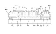
- FIG. 2 is a side view showing the electronic component mounting structure according to the first embodiment;
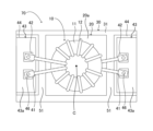
- FIG. 2 is a top view showing the electronic component mounting structure according to the first embodiment;
- FIG. 2 is a top view showing a mounting structure for electronic components according to a second embodiment;
- FIG. 4 is a top view showing an electronic component mounting structure according to a fourth embodiment;
- FIG. 11 is a top view showing an electronic component mounting structure according to a fifth embodiment;
- FIG. 11 is a top view showing an electronic component mounting structure according to a sixth embodiment; The side view showing another electronic component mounting structure according to the sixth embodiment. A top view showing another electronic component mounting structure according to the sixth embodiment.
- Block diagram showing the configuration of an air conditioner according to Embodiment 7 Refrigerant circuit diagram showing a refrigeration cycle of an air conditioner according to Embodiment 7 1 is a first conceptual diagram showing the configuration of an outdoor unit of an air conditioner to which the electronic component mounting structure according to any one of Embodiments 1 to 6 is attached.
- FIG. 1 is a side view showing an electronic component mounting structure 70 according to the first embodiment.
- FIG. 2 is a top view showing the electronic component mounting structure 70 according to the first embodiment.
- FIG. 2 shows the electronic component 10 viewed from above.
- the electronic component mounting structure 70 is a mounting structure for the electronic component 10 that can suppress the vibration of the electronic component 10 and efficiently dissipate the heat generated in the electronic component 10 .
- an electronic component mounting structure 70 includes an electronic component 10 , a heat dissipation component 20 having flexibility and elasticity, and a metal plate 30 having one surface 31 and the other surface 32 .
- the heat radiating component 20 and the electronic component 10 are mounted on one surface 31 of the metal plate 30 in this order from the bottom.
- One surface 31 of metal plate 30 is the upper surface of metal plate 30, which is the surface of metal plate 30 on which heat dissipation component 20 and electronic component 10 are mounted.
- the stacking direction in which the electronic component 10, the heat radiation component 20, and the metal plate 30 are stacked as shown in FIG. 1 is the vertical direction.
- the vertical direction is a direction perpendicular to the in-plane direction of one surface 31 and the other surface 32 of the metal plate 30 .
- the in-plane directions of one surface 31 and the other surface 32 of the metal plate 30 are parallel to the upper surface 20a and the lower surface 20b of the heat dissipation component 20, which will be described later.
- the electronic component 10 is a toroidal coil having a core 11 made of a magnetic material having an annular shape in the in-plane direction of one surface 31 of the metal plate 30 and a winding 12 wound around the core 11 .
- the electronic component 10 is placed and held on the heat dissipation component 20 in a horizontal position.
- the electronic component 10 has a connection terminal 41 attached to the tip of the winding 12 .
- the electronic component 10 is connected to a terminal block 42 provided on an electronic substrate 43 to be described later with screws 46 via connection terminals 41 .
- connection method is not limited.
- the electronic component 10 and the electronic substrate 43 may be connected by a method such as soldering.
- the heat dissipation component 20 is sandwiched between the one surface 31 of the metal plate 30 and the electronic component 10 .
- the heat dissipation component 20 has flexibility and elasticity. Flexibility is the ability of a material to easily deform. Elasticity is the property of an object to change its shape or volume when a force is applied, and to return to its original shape or volume when the applied force is removed. It is a property that has
- the heat dissipation component 20 is fixed to the one surface 31 of the metal plate 30 with the lower surface 20b of the heat dissipation component 20 and the one surface 31 of the metal plate 30 in close contact with each other.
- the shape of a part of the upper surface 20a side of the heat dissipation component 20 changes due to the flexibility of the heat dissipation component 20. It is in close contact with the electronic component 10 in a state of being deformed along the shape of the lower surface 10a side.
- the lower side of the electronic component 10 is the metal plate 30 side of the electronic component 10 .
- the heat dissipation component 20 can hold the electronic component 10 in a state where the electronic component 10 does not move in the heat dissipation component 20 by deforming to a state close to the limit of flexibility.
- the upper surface 20a of the heat dissipation component 20 is the surface of the heat dissipation component 20 on which the electronic component 10 is arranged in the stacking direction.
- the lower surface 20b of the heat dissipation component 20 is the surface of the heat dissipation component 20 on which the metal plate 30 is arranged in the stacking direction.
- An insulating heat dissipation sheet for example, is used for the heat dissipation component 20 .
- the upper surface 20a of the heat dissipation component 20, which is the surface of the heat dissipation component 20 facing the lower part of the electronic component 10 is made adhesive to prevent the upper surface 20a of the heat dissipation component 20 from separating from the lower part of the electronic component 10.
- the upper surface 20a of the heat dissipation component 20 and the lower part of the electronic component 10 can be brought into close contact with each other. Note that the method of adhering the upper surface 20a of the heat dissipation component 20 and the lower part of the electronic component 10 so as not to separate is not limited.
- the lower surface 20b of the heat dissipating component 20, which is the surface facing the one surface 31 of the metal plate 30 of the heat dissipating component 20, is made adhesive so that the lower surface 20b of the heat dissipating component 20 and the one surface 31 of the metal plate 30
- the lower surface 20b of the heat radiating component 20 and the one surface 31 of the metal plate 30 can be brought into close contact so that they do not separate.
- the method of adhering the lower surface 20b of the heat dissipation component 20 and the one surface 31 of the metal plate 30 is not limited.
- the heat dissipation component 20 may be fixed while sticking to one surface 31 of the metal plate 30 .
- the bottom surface 20b of the heat dissipation component 20 and the one surface 31 of the metal plate 30, which are the contact surfaces between the heat dissipation component 20 and the metal plate 30, may be formed with unevenness that fits together.
- the heat dissipation component 20 is fixed to the one surface 31 of the metal plate 30 by fitting the irregularities formed on the heat dissipation component 20 and the metal plate 30 to each other.
- the heat dissipation component 20 has a function of dissipating heat generated in the electronic component 10 due to the operation of the electronic component 10 .
- Heat dissipation component 20 is thermally connected to electronic component 10 by being in direct contact with the lower portion of electronic component 10 as described above. That is, the heat generated in the electronic component 10 is transferred to the heat dissipation component 20 . Then, the heat dissipation component 20 can function as a heat dissipation part that dissipates the heat of the electronic component 10 that is transferred from the electronic component 10 .
- heat dissipation component 20 is thermally connected to the metal plate 30 by being in direct contact with the one surface 31 of the metal plate 30 as described above.
- heat dissipation component 20 has a function of transferring heat generated in electronic component 10 to metal plate 30 when electronic component 10 operates.
- the metal plate 30 is a base substrate on which the heat dissipation component 20 and the electronic component 10 are mounted in the electronic component mounting structure 70 .
- Metal plate 30 has a function of dissipating heat generated in electronic component 10 when electronic component 10 operates.
- Metal plate 30 is thermally connected to electronic component 10 via heat dissipation component 20 . That is, the heat generated by the electronic component 10 is transferred to the metal plate 30 via the heat dissipation component 20 .
- the metal plate 30 functions as a heat radiating portion that radiates the heat of the electronic component 10 that is transferred through the heat radiating component 20 .
- the electronic component mounting structure 70 from the viewpoint of the function of the base substrate and the function of the heat dissipating part that dissipates the heat of the electronic component 10, a material having relatively high mechanical strength and thermal conductivity among various materials A metal plate 30 made of a metal is employed.
- two electronic boards 43 are arranged above one surface 31 of the metal plate 30 so as to sandwich the heat dissipation component 20 and the electronic component 10 in the in-plane direction of the one surface 31 .
- An upper surface 43 a of the electronic board 43 is provided with a terminal block 42 for electrically connecting the electronic board 43 to the connection terminals 41 attached to the ends of the windings 12 of the electronic component 10 .
- the upper surface 43 a of the electronic substrate 43 is a surface that faces the surface of the electronic substrate 43 that faces the metal plate 30 .
- the electronic board 43 is held and fixed by a board holder 44 made of a material such as resin.
- the substrate holder 44 is attached and fixed to the metal plate 30 via a support 45 fixed to one surface 31 of the metal plate 30 . That is, the substrate holder 44 is arranged in a state spaced upward from the one surface 31 of the metal plate 30 and holds the electronic substrate 43 .
- a gap 50 is formed between the substrate holder 44 and the metal plate 30 .
- a gap 51 is formed between the substrate holder 44 and the heat dissipation component 20 .
- a gap 51 is formed between the heat dissipation component 20 and the board holder 44 in the electronic component mounting structure 70 . Therefore, in the electronic component mounting structure 70 , heat can be radiated from the side surface of the heat radiating component 20 facing the substrate holder 44 .
- the heat dissipation component 20 having the flexibility is such that the upper surface 20a of the heat dissipation component 20 on which the electronic component 10 is mounted is the lower part of the electronic component 10.
- the electronic component 10 is held in a deformed state along the shape of .
- the electronic component 10 is held by the heat dissipation component 20 with the lower portion of the electronic component 10 buried in the heat dissipation component 20 and in close contact with the upper surface 20 a of the heat dissipation component 20 . Fixed.
- the heat dissipation component 20 on which the electronic component 10 is mounted is such that the upper surface 20a side of the heat dissipation component 20 is in contact with the shape of the winding 12 of the electronic component 10 that generates heat during operation of the electronic component 10 and the winding 12. It deforms along the shape of the core 11 to which the heat generated in the winding 12 is transferred. Then, the electronic component 10 is embedded in the heat radiation component 20 deformed along the shape of the winding 12 and the shape of the core 11 of the lower part of the electronic component 10, and the winding of the lower part of the electronic component 10 is buried. The wire 12 and the core 11 are held and fixed to the heat dissipation component 20 in a state of being in close contact with the upper surface 20a side of the heat dissipation component 20 .
- the heat dissipation component 20 deforms according to the uneven shape of the lower portion of the electronic component 10 due to the flexibility of the heat dissipation component 20 , and the electronic component 20 moves along the uneven shape of the lower portion of the electronic component 10 . It holds the electronic component 10 in close contact with the lower part of the component 10 .
- the heat dissipation component 20 mounted on the metal plate 30 is such that the lower surface 20 b side of the heat dissipation component 20 faces the one surface 31 of the metal plate 30 . It can deform along the shape. That is, in the electronic component mounting structure 70 , the heat dissipation component 20 is deformed according to the uneven shape of the one surface 31 of the metal plate 30 , and moves along the uneven shape of the one surface 31 of the metal plate 30 to the one surface 31 of the metal plate 30 . Tight and fixed.
- the electronic component mounting structure 70 a large contact area is secured between the heat dissipation component 20 and the electronic component 10, and the degree of adhesion between the heat dissipation component 20 and the electronic component 10 is increased. Moreover, in the electronic component mounting structure 70 , a large contact area is ensured between the heat dissipation component 20 and the metal plate 30 , and the degree of adhesion between the heat dissipation component 20 and the metal plate 30 is increased.
- heat generated in the electronic component 10 during operation of the electronic component 10 can be efficiently transferred to the metal plate 30 via the heat dissipation component 20 .
- the thermal resistance between the plate 30 can be lowered, and the heat dissipation performance of the heat generated in the electronic component 10 can be enhanced.
- the heat dissipation component 20 is in close contact with the electronic component 10 and the metal plate 30. Therefore, even if vibration is applied to the electronic component mounting structure 70, the electronic component 10 does not vibrate. can be suppressed.
- the connection terminal 41 or the terminal block 42 which is the connection portion between the electronic component 10 and the electronic substrate 43, is prevented from fatigue failure due to the vibration of the electronic component 10. is prevented.
- a connecting portion between the electronic component 10 and the electronic substrate 43 includes a connecting terminal 41 , a terminal block 42 , and a screw 46 .
- the gap 51 is formed between the heat dissipation component 20 and the substrate holder 44 , so that the substrate holder 44 can deform the heat dissipation component 20 in the in-plane direction of the one surface 31 of the metal plate 30 . does not interfere with Accordingly, in the electronic component mounting structure 70 , the heat radiating component 20 can be easily brought into close contact with the shape of the lower portion of the electronic component 10 , and can be brought into close contact with the uneven shape of the one surface 31 of the metal plate 30 .
- the electronic component 10 has an annular shape in the in-plane direction of the one surface 31 of the metal plate 30 and is placed horizontally.
- the mounting structure 71 of the electronic component is arranged such that the lower surface 10a of the electronic component 10, which is one surface perpendicular to the center axis C of the annular shape of the electronic component 10, is in contact with the upper surface 20a of the heat dissipation component 20 in a facing manner. are placed.
- a lower surface 10 a of electronic component 10 includes a lower surface of core 11 and windings 12 wound around the lower surface of core 11 .
- the heat radiating component 20 is attached to the lower surface 10 a of the electronic component 10 that is perpendicular to the central axis C of the electronic component 10 . That is, in the electronic component mounting structure 71, when the electronic component 10 is horizontally placed and mounted on the heat dissipating component 20, the contact area of the heat dissipating component 20 with the upper surface 20a of the heat dissipating component 20, which is the mounting surface of the electronic component 10, is The electronic component 10 is mounted with the lower surface 10a of the heat dissipation component 20, which is relatively larger than the other surfaces, facing the upper surface 20a of the heat dissipation component 20. As shown in FIG.
- the electronic component 10 has an annular shape in the in-plane direction of the one surface 31 of the metal plate 30, and the lower surface 10a perpendicular to the central axis C of the annular shape of the electronic component 10 faces the upper surface 20a of the heat dissipation component 20. It can be said that they are arranged in a state in which they are in contact with each other.
- the electronic component mounting structure 70 a large contact area between the electronic component 10 and the heat dissipation component 20 can be ensured.
- the degree of adhesion between the electronic component 10 and the heat dissipation component 20 is further increased, so that the connection terminal 41 or the connection terminal 41 or The terminal block 42 is prevented from being fatigue-broken due to the vibration of the electronic component 10 .
- a large contact area can be secured between the electronic component 10 and the heat dissipation component 20, so that the heat generated in the electronic component 10 during operation of the electronic component 10 can be more effectively dissipated.
- Heat can be efficiently transferred to the metal plate 30 through the component 20, the thermal resistance between the electronic component 10 and the metal plate 30 can be reduced, and the heat dissipation performance of the heat generated in the electronic component 10 can be improved.
- the heat dissipation performance of the heat generated in the electronic component 10 is enhanced, thereby suppressing the temperature rise of the electronic component 10 and suppressing the operation of the electronic component 10 caused by the temperature rise of the electronic component 10 . Defects can be prevented.
- the electronic component 10 is a toroidal coil, but the type of the electronic component 10 is not limited to the toroidal coil.
- the vibration of the electronic component 10 can be suppressed by the heat radiation component 20 having flexibility and elasticity being in close contact with the electronic component 10 and the metal plate 30.
- the electronic component mounting structure 71 it is possible to prevent the electronic component 10 from vibrating during transportation of the product and causing fatigue failure at the connection portion between the electronic component 10 and the electronic substrate 43 .
- the heat transfer performance from the electronic component 10 to the metal plate 30 is enhanced, the heat radiation performance of the electronic component 10 is enhanced, and the vibration of the electronic component 10 is suppressed. It has the effect of being able to
- FIG. 3 is a side view showing an electronic component mounting structure 71 according to the second embodiment.
- FIG. 4 is a top view showing an electronic component mounting structure 71 according to the second embodiment.
- symbol shall be attached
- the heat dissipation component 20 has a disc shape in accordance with the shape of the electronic component 10 in the in-plane direction of the one surface 31 of the metal plate 30 . 1 is different from the electronic component mounting structure 70 according to 1.
- the electronic component mounting structure 71 having the configuration described above is the electronic component mounting structure according to the first embodiment described above, except that the heat dissipation component 20 has a disk shape in the in-plane direction of the one surface 31 of the metal plate 30. It has the same structure as 70. Therefore, the electronic component mounting structure 71 has the same effects as the electronic component mounting structure 70 according to the first embodiment.
- the heat dissipation component 20 having a shape along the shape of the electronic component 10 in the in-plane direction of the one surface 31 of the metal plate 30 is used. Therefore, in the electronic component mounting structure 71 , the size of the heat dissipation component 20 can be reduced while leaving a portion of the heat dissipation component 20 with a high heat dissipation effect for the heat generated in the electronic component 10 .
- the portion of the heat dissipation component 20 where the heat generated in the electronic component 10 is highly effectively dissipated is the region of the heat dissipation component 20 corresponding to the annular shape of the electronic component 10 in the in-plane direction of the one surface 31 of the metal plate 30 .
- the electronic component 10 has a disk shape in the in-plane direction of the one surface 31 of the metal plate 30 .
- the heat dissipation component 20 has a disc shape that is larger than the disc shape of the electronic component 10 in the in-plane direction of the one surface 31 of the metal plate 30 and follows the shape of the electronic component 10 .
- the disc shape of electronic component 10 and the disc shape of heat dissipation component 20 are arranged coaxially.
- the electronic component mounting structure 71 is lower in cost than the electronic component mounting structure 70 according to the first embodiment described above, and the heat transfer performance from the electronic component 10 to the metal plate 30 is improved.
- the vibration of the electronic component 10 can be suppressed while enhancing the heat radiation performance. Therefore, in the electronic component mounting structure 71, the cost is lower than that of the electronic component mounting structure 70, and the connection between the electronic component 10 and the electronic substrate 43 caused by the vibration of the electronic component 10 during the transportation of the product. It is possible to prevent fatigue failure of the terminal 41 or the terminal block 42 .
- FIG. 5 is a side exploded view showing an electronic component mounting structure 72 according to the third embodiment.
- symbol shall be attached
- the concave portion 23 having a shape along the shape of the lower portion of the electronic component 10 is formed on the side of the upper surface 20a of the heat dissipation component 20, which is similar to that of the first embodiment described above. It is different from the mounting structure 70 for the electronic components according to .
- the electronic component mounting structure 72 having the configuration described above is the same as that of the first embodiment described above, except that the concave portion 23 having a shape that follows the shape of the lower portion of the electronic component 10 is formed on the upper surface 20a side of the heat dissipation component 20 . It has the same structure as the mounting structure 70 of the electronic component. Therefore, the electronic component mounting structure 72 has the same effects as the electronic component mounting structure 70 according to the first embodiment.
- the heat dissipation component 20 can be said to have the concave portion 23 formed along the shape of the contact portion where the electronic component 10 contacts the heat dissipation component 20 . Therefore, in the electronic component mounting structure 72 , the heat dissipation component 20 is more likely to come into close contact with the lower portion of the electronic component 10 . As a result, the electronic component mounting structure 72 improves the heat transfer performance from the electronic component 10 to the metal plate 30 more effectively than the electronic component mounting structure 70 according to the first embodiment. The heat radiation performance of the component 10 can be improved and the vibration of the electronic component 10 can be suppressed.
- the connecting portion of the electronic component 10 with the electronic substrate 43 caused by the vibration of the electronic component 10 during the transportation of the product can be effectively prevented. It is possible to prevent fatigue failure of the connection terminal 41 or the terminal block 42 .
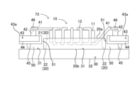
- FIG. 6 is a side view showing an electronic component mounting structure 73 according to the fourth embodiment.
- FIG. 7 is a top view showing an electronic component mounting structure 73 according to the fourth embodiment.
- symbol shall be attached
- the heat dissipation component 20 has the first heat dissipation component 21 and the second heat dissipation component 22, which are two types of heat dissipation components 20 having different flexibility and elasticity, and the electronic component A first heat radiation component 21 having relatively high flexibility is arranged in a portion in contact with the component 10, and a second heat radiation component 22 having relatively high elasticity is arranged in a portion not in contact with the electronic component 10. It is different from the electronic component mounting structure 70 according to the first embodiment described above.
- the electronic component mounting structure 73 having the configuration described above has the first heat dissipation component 21 and the second heat dissipation component 22, which are two types of heat dissipation components 20 having different flexibility and elasticity. It has the same structure as the electronic component mounting structure 70 according to the first embodiment described above, except that the first heat radiation component 21 having relatively high flexibility is arranged on the surface in contact with the electronic component 10 . Therefore, the electronic component mounting structure 73 has the same effects as the electronic component mounting structure 70 according to the first embodiment.
- the first heat dissipation component 21 is a heat dissipation component 20 having flexibility and elasticity in the electronic component mounting structure 73 , and is a heat dissipation component 20 with relatively high flexibility compared to the second heat dissipation component 22 .
- the second heat dissipation component 22 is a heat dissipation component 20 having flexibility and elasticity in the electronic component mounting structure 73 , and is a heat dissipation component 20 with relatively high elasticity compared to the first heat dissipation component 21 .
- first heat radiation component 21 having relatively high flexibility is arranged in a portion in contact with the electronic component 10 .
- first heat dissipation component 21 is provided in a quadrangular shape that includes core 11 of electronic component 10 in the in-plane direction of one surface 31 of metal plate 30 .
- electronic component mounting structure 73 secures a wide contact area between heat dissipation component 20 and electronic component 10 as described in the first embodiment, and also provides heat dissipation.
- the degree of adhesion between the component 20 and the electronic component 10 increases.
- the heat generated in the electronic component 10 during operation of the electronic component 10 can be efficiently transferred to the metal plate 30 via the heat dissipation component 20. 30 can be reduced, and the heat dissipation performance of the heat generated in the electronic component 10 can be enhanced.
- the second heat radiation component 22 with relatively high elasticity is arranged in a portion that does not come into contact with the electronic component 10 .
- the second heat dissipation component 22 surrounds the square shape of the first heat dissipation component 21 from the outer peripheral side of the first heat dissipation component 21 in the in-plane direction of the one surface 31 of the metal plate 30 . It is shaped like a frame. That is, the first heat dissipation component 21 and the second heat dissipation component 22 are arranged in the in-plane direction of the one surface 31 of the metal plate 30.
- the first heat dissipation component having relatively high flexibility is located near the central axis C of the electronic component 10. 21 is arranged, and a second heat radiation component 22 having relatively high elasticity is arranged in a region far from the central axis C of the electronic component 10 .
- the height of the first heat radiation component 21 and the height of the second heat radiation component 22 are the same size.
- the first heat dissipation component 21 is flexible so that the metal plate 30 does not move from the metal plate 30 .
- the electronic component 10 vibrates in the same manner as in the electronic component mounting structure 70 according to the first embodiment. can be suppressed.
- the connection terminal 41 or the terminal block 42 which is the connection portion between the electronic component 10 and the electronic substrate 43, is prevented from fatigue failure due to the vibration of the electronic component 10. is prevented. Therefore, in the electronic component mounting structure 73 in which the heat dissipating component 20 is composed of the first heat dissipating component 21 and the second heat dissipating component 22, the heat dissipating component 20 of the electronic component mounting structure 70 according to the first embodiment is similar to the heat dissipating component 20. effect is obtained.
- the first heat dissipation component 21 is arranged in a region close to the central axis C of the electronic component 10, and the first heat dissipation component 21 is arranged in a region far from the central axis C of the electronic component 10.
- the arrangement of the first heat dissipation component 21 and the second heat dissipation component 22 is not limited to the above arrangement.
- the arrangement of the first heat-radiating component 21 and the second heat-radiating component 22 can be changed as appropriate without departing from the scope of the effects of the electronic component mounting structure 73 according to the fourth embodiment described above.
- FIG. 8 is a side view showing an electronic component mounting structure 74 according to the fifth embodiment.
- FIG. 9 is a top view showing an electronic component mounting structure 74 according to the fifth embodiment.
- symbol shall be attached
- the heat dissipation component 20 is also arranged between the board holder 44 that holds the electronic board 43 fixedly and the metal plate 30 in the in-plane direction of the one surface 31 of the metal plate 30. This is different from the electronic component mounting structure 70 according to the first embodiment described above.
- the heat dissipating component 20 is also arranged between the substrate holder 44 that secures and holds the electronic substrate 43 and the metal plate 30 in the in-plane direction of the one surface 31 of the metal plate 30 . It has the same structure as the electronic component mounting structure 70 according to the first embodiment described above, except that the electronic component mounting structure 70 of FIG. Therefore, the electronic component mounting structure 74 has the same effects as the electronic component mounting structure 70 according to the first embodiment.
- the heat dissipation component 20 placed in the gap 50 between the substrate holder 44 and the metal plate 30 is deformed by the downward pressing force received from the substrate holder 44 , and the one surface of the metal plate 30 is deformed. Adhering to 31.
- the electronic board 43 held by the board holder 44 is thermally connected to the one surface 31 of the metal plate 30 via the board holder 44 and the heat dissipation component 20 .
- the downward pressing force received from the substrate holder 44 is the pressing force received from the substrate holder 44 in the direction perpendicular to the in-plane direction of the one surface 31 of the metal plate 30 and in the direction from the heat dissipation component 20 toward the metal plate 30 . is the pressing force.
- the heat dissipation component 20 is arranged on the one surface 31 of the metal plate 30 including the gap 50 between the board holder 44 and the metal plate 30, it is fixed to the one surface 31 of the metal plate 30.
- a substrate holder 44 is attached and fixed to the metal plate 30 via a support 45 .
- the downward pressing force described above is applied to the heat dissipation component 20 between the substrate holder 44 and the metal plate 30 from the upper surface 20 a side of the heat dissipation component 20 toward the metal plate 30 .
- the heat dissipation component 20 arranged between the substrate holder 44 and the metal plate 30 is provided with a through hole through which the column 45 passes.
- the substrate holder 44 is spaced upward from the one surface 31 of the metal plate 30 , and a part of the heat radiating component 20 extends from the substrate holder 44 in the in-plane direction of the metal plate 30 . It is sandwiched between the protruding lower surface of the electronic substrate 43 or the lower surface of the substrate holder 44 and the one surface 31 of the metal plate 30 , and is deformed by the downward force applied from the substrate holder 44 to adhere to the one surface 31 of the metal plate 30 . , an electronic component mounting structure in which the electronic component 10 and the electronic substrate 43 are electrically connected through a part of the heat dissipation component 20 is realized.
- the heat dissipation component 20 placed between the substrate holder 44 and the metal plate 30 is deformed by the downward pressing force received from the substrate holder 44 . Adhesion is further improved.
- the heat transfer performance from the electronic component 10 to the metal plate 30 is improved more reliably than in the electronic component mounting structure 70 according to the first embodiment. It is possible to improve the heat radiation performance of the electronic component 10 and suppress the vibration of the electronic component 10 . Therefore, in the electronic component mounting structure 74, as compared with the electronic component mounting structure 70, the connection portion of the electronic component 10 with the electronic substrate 43 caused by the vibration of the electronic component 10 during transportation of the product is more reliable. A certain connection terminal 41 or terminal block 42 can be prevented from fatigue failure.
- the heat dissipation component 20 enters the gap 50 between the substrate holder 44 and the metal plate 30 , so that the electronic board 43 moves between the board holder 44 and the heat dissipation component 20 arranged in the gap 50 . is thermally connected to one surface 31 of the metal plate 30 via the . Therefore, in the electronic component mounting structure 74 , the heat generated in the electronic board 43 during operation of the electronic board 43 can be transferred to the metal plate 30 via the board holder 44 and the heat dissipation component 20 arranged in the gap 50 . It becomes possible.
- the heat dissipation performance of the heat generated in the electronic substrate 43 can be enhanced, and the electronic substrate 43 can be cooled.
- the temperature rise of the electronic board 43 is suppressed by cooling the electronic board 43, and malfunction of the electronic board 43 caused by the temperature rise of the electronic board 43 can be prevented. can.
- FIG. 10 is a side view showing an electronic component mounting structure 75 according to the sixth embodiment.
- FIG. 11 is a top view showing an electronic component mounting structure 75 according to the sixth embodiment.
- symbol shall be attached
- the electronic substrate 43 and the substrate holder 44 have an opening formed in a region corresponding to the position where the electronic component 10 is arranged. It is different from the electronic component mounting structure 70 according to the first form.
- Embodiment 1 as shown in FIGS. 1 and 2, two electronic substrates 43 are arranged so as to sandwich heat dissipation component 20 and electronic component 10 in the in-plane direction of one surface 31 of metal plate 30.
- two substrate holders 44 are arranged so as to sandwich heat dissipation component 20 and electronic component 10 in the in-plane direction of one surface 31 of metal plate 30.
- one substrate holder 44 is arranged above the one surface 31 of the metal plate 30, as shown in FIGS.
- one electronic substrate 43 is held by one substrate holder 44 as shown in FIGS. 10 and 11 .
- An opening 43b is formed in the electronic substrate 43 in a region corresponding to the position where the electronic component 10 is arranged in the in-plane direction of the one surface 31 of the metal plate 30 .
- the board holder 44 is formed with an opening 44a in a region corresponding to the position where the electronic component 10 is arranged in the in-plane direction of the one surface 31 of the metal plate 30 .
- the opening 43b of the electronic substrate 43 is formed at a position that includes the opening 44a of the substrate holder 44 in the in-plane direction of the one surface 31 of the metal plate 30 . Further, the opening 44 a of the substrate holder 44 and the opening 43 b of the electronic substrate 43 are formed at positions that include the core 11 of the electronic component 10 in the in-plane direction of the one surface 31 of the metal plate 30 .
- the substrate holder 44 for fixing and holding the electronic substrate 43 in the in-plane direction of the one surface 31 of the metal plate 30 is mounted. and the metal plate 30, the heat dissipation component 20 is also arranged.
- the electronic component 10 is arranged in a state of protruding upward from the opening 44 a of the substrate holder 44 and the opening 43 b of the electronic substrate 43 . Part of the heat dissipation component 20 is exposed from the opening 44 a of the board holder 44 and the opening 43 b of the electronic board 43 .
- the electronic components are placed inside the opening 44 a formed in the substrate holder 44 and the opening 43 b formed in the electronic substrate 43 in the in-plane direction of the one surface 31 of the metal plate 30 . Since the component 10 is arranged, it becomes possible to attach the electronic component 10 and the electronic substrate 43 closer to each other. Accordingly, in the electronic component mounting structure 75, the mounting structure for the electronic component 10 can be realized in a small size and at a low cost.
- the substrate holder 44 is formed with the opening 44a and the electronic substrate 43 is formed with the opening 43b.
- the structure that enables this is not limited to the structure in which the openings 44a and 43b are formed.
- the electronic component mounting structure 70 shown in FIGS. 1 and 2 of the first embodiment described above in the in-plane direction of the one surface 31 of the metal plate 30, the electronic substrate 43 and the substrate holder 44, and the electronic component 10 Let us consider a case where the electronic component 10 and the board holder 44 are brought closer to the electronic board 43 so as not to overlap each other.
- FIG. 12 is a side view showing another electronic component mounting structure 76 according to the sixth embodiment.
- FIG. 13 is a top view showing another electronic component mounting structure 76 according to the sixth embodiment.
- the electronic substrate 43 and the substrate holder 44 have notches formed in regions corresponding to the positions where the electronic components 10 are arranged. It is different from the electronic component mounting structure 75 according to the sixth embodiment.
- one surface 31 of the metal plate 30 has one A substrate holder 44 is arranged.
- one electronic substrate 43 is mounted on one substrate holder 44, similar to the electronic component mounting structure 75 according to the sixth embodiment. is retained.
- a notch 43 c is formed in the electronic substrate 43 in a region corresponding to the position where the electronic component 10 is arranged in the in-plane direction of the one surface 31 of the metal plate 30 .
- the board holder 44 is formed with a notch 44b in a region corresponding to the position where the electronic component 10 is arranged in the in-plane direction of the one surface 31 of the metal plate 30 .
- the notch 43c of the electronic substrate 43 is formed at a position including the notch 44b of the substrate holder 44 except for a part of the side where the notch 43c is opened in the in-plane direction of the one surface 31 of the metal plate 30.
- the notch 44 b of the board holder 44 and the notch 43 c of the electronic board 43 are formed at positions that include the core 11 of the electronic component 10 in the in-plane direction of the one surface 31 of the metal plate 30 .
- a substrate for fixing and holding the electronic substrate 43 is provided, as in the electronic component mounting structure 75 according to the sixth embodiment.
- a heat dissipation component 20 is also arranged between the holder 44 and the metal plate 30 .
- the electronic component 10 is arranged in a state of protruding upward from the notch 44 b of the board holder 44 and the notch 43 c of the electronic board 43 .
- Part of the heat dissipation component 20 is exposed through the notch 44b of the board holder 44 and the notch 43c of the electronic board 43. As shown in FIG.
- the other electronic component mounting structure 76 having the configuration described above, the inside of the notch 44b formed in the substrate holder 44 and the notch 43c formed in the electronic substrate 43 in the in-plane direction of the one surface 31 of the metal plate 30 Since the electronic component 10 is arranged at the position of the electronic component 10, it is possible to mount the electronic component 10 and the electronic substrate 43 closer to each other, similarly to the electronic component mounting structure 75 according to the sixth embodiment. As a result, in the other electronic component mounting structure 76, a mounting structure for the electronic component 10 can be realized in a small size and at a low cost, like the electronic component mounting structure 75 according to the sixth embodiment.
- electronic substrate 43 and substrate holder 44 are provided with openings or notches at positions where electronic component 10 is arranged in the in-plane direction of metal plate 30.
- a mounting structure is realized.
- a structure in which an opening 44a is formed in the substrate holder 44 and an opening 43b is formed in the electronic substrate 43, or a structure in which notches are formed in the substrate holder 44 and the electronic substrate 43 can be arbitrarily selected. It should be selected.
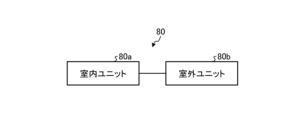
- FIG. 14 is a block diagram showing the configuration of an air conditioner 80 according to Embodiment 7.
- FIG. 15 is a refrigerant circuit diagram showing a refrigerating cycle 110 of an air conditioner 80 according to Embodiment 7.
- an air conditioner 80 according to Embodiment 7 includes an indoor unit 80a installed indoors and an outdoor unit 80b installed outdoors.
- symbol shall be attached
- the indoor unit 80a, the refrigerant pipe 152, the outdoor unit 80b, and the refrigerant pipe 151 constitute a refrigerant circulation circuit.
- the compressor 132, the four-way valve 131, the outdoor heat exchanger 133, the expansion valve 123, and the indoor heat exchanger 121 are sequentially connected in an annular manner using the refrigerant pipe 151 and the refrigerant pipe 152, and the refrigeration is performed.
- a cycle 110 is constructed.
- the refrigerant pipe 151 and the refrigerant pipe 152 are pipes that connect the indoor heat exchanger 121 of the indoor unit 80a and the outdoor heat exchanger 133 of the outdoor unit 80b to circulate the refrigerant. Part of the refrigerant circuit.
- an indoor fan 122 that forms an airflow passing through the indoor heat exchanger 121 is installed in the indoor unit 80a.
- the indoor fan 122 operates by driving an indoor propeller 122a by an indoor motor 122b.
- An outdoor fan 134 that forms an airflow passing through the outdoor heat exchanger 133 is installed in the outdoor unit 80b.
- the outdoor blower 134 operates by driving an outdoor propeller 134a by an outdoor motor 134b.
- FIG. 16 is a first conceptual diagram showing the configuration of an outdoor unit 80b of an air conditioner 80 to which the electronic component mounting structure according to any one of Embodiments 1 to 6 is attached.
- FIG. 16 shows a conceptual diagram of the outdoor unit 80b viewed from above.
- FIG. 17 is a second conceptual diagram showing the configuration of an outdoor unit 80b of an air conditioner 80 to which the electronic component mounting structure according to any one of Embodiments 1 to 6 is attached.
- FIG. 17 shows a conceptual diagram when the outdoor unit 80b is viewed from the side.
- FIG. 18 is a third conceptual diagram showing the configuration of an outdoor unit 80b of an air conditioner 80 to which the electronic component mounting structure according to any one of Embodiments 1 to 6 is attached.
- FIG. 18 shows a conceptual diagram when the outdoor unit 80b is viewed obliquely from above.
- FIGS. 16 to 18 show part of the structure of the outdoor unit 80b when part of the housing 61 of the outdoor unit 80b is removed.
- the metal plate 30 in the electronic component mounting structure according to any one of Embodiments 1 to 6 serves as a partition, and the inside of the rectangular parallelepiped box-shaped housing 61 is It has a structure divided into a machine room 63 and a blower room 64 .
- the code "30, 62" in FIGS. 16 to 18 is understood as the code "30”.
- the electronic components 10 are arranged in the machine room 63 and the outdoor blower 134 is arranged in the blower room 64 .
- a compressor 132 is arranged in the machine room 63 .
- An outdoor heat exchanger 133 is arranged in the blower room 64 .
- the heat generated in the electronic component 10 and transferred to the metal plate 30 via the heat radiation component 20 is exhausted to the air on the blower chamber 64 side, whereby the electronic component
- the heat radiation performance of 10 or metal plate 30 is greatly improved, and electronic component 10 can be efficiently cooled.
- a radiator may be attached to the metal plate 30 .
- the heat radiator includes, for example, a heat sink made of metal.
- the outdoor unit 80b of the air conditioner 80 is attached to the mounting plate 62 on the other surface 32 side of the metal plate 30, the mounting plate 62 serves as a partition, and the inside of the rectangular parallelepiped box-shaped housing 61 is divided into a machine room 63 and a fan room. 64.
- the mounting plate 62 serves as a partition, the reference numerals "30, 62" in FIGS. 16 to 18 are understood as the reference numeral "62".
- the other surface 32 side of the metal plate 30 is attached to the mounting plate 62, so that the electronic component mounting structure can be more easily attached to and detached from the outdoor unit 80b. It is possible to install the outdoor unit 80b, and it is possible to improve the assembling efficiency of the outdoor unit 80b and the maintenance serviceability of the outdoor unit 80b.
- the mounting structure between the other surface 32 of the metal plate 30 and the mounting plate 62 includes screwing, but the mounting structure between the other surface 32 of the metal plate 30 and the mounting plate 62 is not limited.
- the mounting structure between the other surface 32 of the metal plate 30 and the mounting plate 62 can be changed as appropriate without departing from the scope of the effects of the mounting structure between the other surface 32 of the metal plate 30 and the mounting plate 62 .
Landscapes
- Engineering & Computer Science (AREA)
- Power Engineering (AREA)
- Chemical & Material Sciences (AREA)
- Combustion & Propulsion (AREA)
- Mechanical Engineering (AREA)
- General Engineering & Computer Science (AREA)
- Cooling Or The Like Of Electrical Apparatus (AREA)
Abstract
Description
図1は、実施の形態1にかかる電子部品の搭載構造70を示す側面図である。図2は、実施の形態1にかかる電子部品の搭載構造70を示す上面図である。図2においては、電子部品10の上方から見た状態を示している。
図3は、実施の形態2にかかる電子部品の搭載構造71を示す側面図である。図4は、実施の形態2にかかる電子部品の搭載構造71を示す上面図である。なお、実施の形態2では、上述した実施の形態1と同一の構成要素には、同一の符号を付し、詳細な説明を省略するものとする。
図5は、実施の形態3にかかる電子部品の搭載構造72を示す側面分解図である。なお、実施の形態3では、上述した実施の形態1と同一の構成要素には、同一の符号を付し、詳細な説明を省略するものとする。
図6は、実施の形態4にかかる電子部品の搭載構造73を示す側面図である。図7は、実施の形態4にかかる電子部品の搭載構造73を示す上面図である。なお、実施の形態4では、上述した実施の形態1と同一の構成要素には、同一の符号を付し、詳細な説明を省略するものとする。
図8は、実施の形態5にかかる電子部品の搭載構造74を示す側面図である。図9は、実施の形態5にかかる電子部品の搭載構造74を示す上面図である。なお、実施の形態5では、上述した実施の形態1と同一の構成要素には、同一の符号を付し、詳細な説明を省略するものとする。
図10は、実施の形態6にかかる電子部品の搭載構造75を示す側面図である。図11は、実施の形態6にかかる電子部品の搭載構造75を示す上面図である。なお、実施の形態6では、上述した実施の形態1と同一の構成要素には、同一の符号を付し、詳細な説明を省略するものとする。
図14は、実施の形態7にかかる空気調和装置80の構成を示すブロック図である。図15は、実施の形態7にかかる空気調和装置80の冷凍サイクル110を示す冷媒回路図である。図14および図15に示すように、実施の形態7にかかる空気調和装置80は、室内に設置された室内ユニット80aおよび室外に設置された室外ユニット80bを備える。なお、各図においては、共通する要素に同一の符号を付し、重複する説明を省略するものとする。
Claims (11)
- 電子部品と、
一面と他面とを有する金属板と、
柔軟性および弾性を有する放熱部品と、
を備え、
前記放熱部品は、前記金属板の一面と前記電子部品とにより挟み込まれ、前記電子部品に対向する領域が前記電子部品の形状に沿って変形して前記電子部品と密着し、前記金属板の一面と密着し、
前記電子部品と前記金属板とが前記放熱部品を介して熱的に接続されている、
電子部品の搭載構造。 - 前記電子部品が、磁性体からなるコアと、前記コアに巻き付けられた巻線と、を有するコイルである、
請求項1に記載の電子部品の搭載構造。 - 前記金属板の一面上に配置された基板ホルダーと、前記基板ホルダー上に保持された電子基板と、を備え、
前記電子部品と前記電子基板とが、前記電子部品と前記電子基板との接続部を介して電気的に接続されている、
請求項1または請求項2に記載の電子部品の搭載構造。 - 前記電子部品は、前記金属板の面内方向において円環形状を有し、前記電子部品の円環形状の中心軸と直交する下面が前記放熱部品の上面と対向して接触する状態で配置されている、
請求項1から3のいずれか1つに記載の電子部品の搭載構造。 - 前記放熱部品は、前記金属板の面内方向において前記電子部品の形状に沿った円盤形状を有する、
請求項4に記載の電子部品の搭載構造。 - 前記放熱部品は、前記電子部品が前記放熱部品と接触する接触部の形状に沿って形成された凹部を有する、
請求項1から5のいずれか1つに記載の電子部品の搭載構造。 - 前記放熱部品は、柔軟性と弾性とが異なる2種類の放熱部品として、柔軟性が相対的に高い第1放熱部品と、弾性が相対的に高い第2放熱部品とを有し、
前記電子部品に接触する面に、前記第1放熱部品が配置されている、
請求項1から6のいずれか1つに記載の電子部品の搭載構造。 - 前記基板ホルダーが、前記金属板の一面から上方に離間して設けられ、
前記放熱部品の一部が、前記金属板の面内方向において、前記金属板の面内方向において前記基板ホルダーからはみ出した前記電子基板の下面または前記基板ホルダーの下面と、前記金属板の一面との間に挟持され、前記基板ホルダーから下方向にかかる力によって変形して前記金属板の一面に密着しており、
前記電子部品と前記電子基板とが、前記放熱部品の一部を介して電気的に接続されている、
請求項3に記載の電子部品の搭載構造。 - 前記電子基板と前記基板ホルダーとは、
前記金属板の面内方向において前記電子部品が配置される位置に開口部あるいは切り欠きが形成されている、
請求項3に記載の電子部品の搭載構造。 - 筐体と、
前記筐体の内部に収容された請求項1から9のいずれか1つに記載の電子部品の搭載構造と、
を備え、
前記筐体の内部に、前記電子部品の搭載構造の前記金属板によって仕切られた送風機室と機械室とが形成されており、
前記機械室に前記電子部品が配置され、
前記送風機室に送風機が配置されている、
空気調和装置の室外ユニット。 - 筐体と、
前記筐体の内部に収容された請求項1から9のいずれか1つに記載の電子部品の搭載構造と、
前記電子部品の搭載構造の前記金属板が取り付けられた取付板と、
を備え、
前記筐体の内部に、前記取付板によって仕切られた送風機室と機械室とが形成されており、
前記機械室に前記電子部品が配置され、
前記送風機室に送風機が配置されている、
空気調和装置の室外ユニット。
Priority Applications (5)
| Application Number | Priority Date | Filing Date | Title |
|---|---|---|---|
| DE112022006754.3T DE112022006754T5 (de) | 2022-02-28 | 2022-02-28 | Elektronikbauteil-Montageträger und Außeneinheit einer Klimaanlage |
| PCT/JP2022/008364 WO2023162249A1 (ja) | 2022-02-28 | 2022-02-28 | 電子部品の搭載構造および空気調和装置の室外ユニット |
| CN202280091832.1A CN118696384A (zh) | 2022-02-28 | 2022-02-28 | 电子部件的搭载构造以及空调装置的室外单元 |
| US18/722,848 US20250052435A1 (en) | 2022-02-28 | 2022-02-28 | Electronic component mounting structure and outdoor unit of air conditioner |
| JP2024502766A JPWO2023162249A1 (ja) | 2022-02-28 | 2022-02-28 |
Applications Claiming Priority (1)
| Application Number | Priority Date | Filing Date | Title |
|---|---|---|---|
| PCT/JP2022/008364 WO2023162249A1 (ja) | 2022-02-28 | 2022-02-28 | 電子部品の搭載構造および空気調和装置の室外ユニット |
Publications (1)
| Publication Number | Publication Date |
|---|---|
| WO2023162249A1 true WO2023162249A1 (ja) | 2023-08-31 |
Family
ID=87765274
Family Applications (1)
| Application Number | Title | Priority Date | Filing Date |
|---|---|---|---|
| PCT/JP2022/008364 Ceased WO2023162249A1 (ja) | 2022-02-28 | 2022-02-28 | 電子部品の搭載構造および空気調和装置の室外ユニット |
Country Status (5)
| Country | Link |
|---|---|
| US (1) | US20250052435A1 (ja) |
| JP (1) | JPWO2023162249A1 (ja) |
| CN (1) | CN118696384A (ja) |
| DE (1) | DE112022006754T5 (ja) |
| WO (1) | WO2023162249A1 (ja) |
Citations (4)
| Publication number | Priority date | Publication date | Assignee | Title |
|---|---|---|---|---|
| JP2012145287A (ja) * | 2011-01-13 | 2012-08-02 | Mitsubishi Electric Corp | 空気調和機の室外ユニット |
| JP2014179478A (ja) * | 2013-03-15 | 2014-09-25 | Omron Automotive Electronics Co Ltd | 電子部品の実装構造 |
| JP2015043377A (ja) * | 2013-08-26 | 2015-03-05 | トヨタ自動車株式会社 | 冷却器付きリアクトル |
| JP2018006650A (ja) * | 2016-07-06 | 2018-01-11 | トヨタ自動車株式会社 | リアクトル |
Family Cites Families (2)
| Publication number | Priority date | Publication date | Assignee | Title |
|---|---|---|---|---|
| JP7228159B2 (ja) | 2019-05-14 | 2023-02-24 | 株式会社豊田自動織機 | トロイダルコイルの搭載構造 |
| JP7349837B2 (ja) * | 2019-07-16 | 2023-09-25 | 株式会社デンソーテン | 発熱部品の放熱構造 |
-
2022
- 2022-02-28 WO PCT/JP2022/008364 patent/WO2023162249A1/ja not_active Ceased
- 2022-02-28 DE DE112022006754.3T patent/DE112022006754T5/de active Pending
- 2022-02-28 US US18/722,848 patent/US20250052435A1/en active Pending
- 2022-02-28 CN CN202280091832.1A patent/CN118696384A/zh active Pending
- 2022-02-28 JP JP2024502766A patent/JPWO2023162249A1/ja active Pending
Patent Citations (4)
| Publication number | Priority date | Publication date | Assignee | Title |
|---|---|---|---|---|
| JP2012145287A (ja) * | 2011-01-13 | 2012-08-02 | Mitsubishi Electric Corp | 空気調和機の室外ユニット |
| JP2014179478A (ja) * | 2013-03-15 | 2014-09-25 | Omron Automotive Electronics Co Ltd | 電子部品の実装構造 |
| JP2015043377A (ja) * | 2013-08-26 | 2015-03-05 | トヨタ自動車株式会社 | 冷却器付きリアクトル |
| JP2018006650A (ja) * | 2016-07-06 | 2018-01-11 | トヨタ自動車株式会社 | リアクトル |
Also Published As
| Publication number | Publication date |
|---|---|
| JPWO2023162249A1 (ja) | 2023-08-31 |
| CN118696384A (zh) | 2024-09-24 |
| DE112022006754T5 (de) | 2025-01-09 |
| US20250052435A1 (en) | 2025-02-13 |
Similar Documents
| Publication | Publication Date | Title |
|---|---|---|
| US7812487B2 (en) | Controller for a direct current brushless motor | |
| JP2008121966A (ja) | 空気調和機の室外機 | |
| US7468555B2 (en) | Heat dissipation structure of an electronic device | |
| JP2003264388A (ja) | 電気部品装置 | |
| US12326265B2 (en) | Outdoor unit for air-conditioning apparatus | |
| JPWO2017158707A1 (ja) | 空気調和機の室外機 | |
| JP2005142379A (ja) | 電子機器装置 | |
| JP5387738B2 (ja) | 電装品ユニット | |
| US20140182818A1 (en) | Heat sink | |
| JP6095627B2 (ja) | 電子部品の冷却構造 | |
| WO2023162249A1 (ja) | 電子部品の搭載構造および空気調和装置の室外ユニット | |
| JP5901233B2 (ja) | 電子部品の冷却構造 | |
| JP4454270B2 (ja) | 電源装置の放熱構造 | |
| JP2008053635A (ja) | 電装品ユニット | |
| JPWO2012098860A1 (ja) | 誘導加熱調理器 | |
| JP2022094454A (ja) | 冷却構造および電子機器 | |
| WO2020208670A1 (ja) | 空気調和装置の室外機 | |
| JP2016127109A (ja) | リアクトルの冷却構造 | |
| JP2016018956A (ja) | 発熱性電子部品を備えたコントローラおよび空気調和機 | |
| JP6410263B2 (ja) | モータ | |
| JP3704250B2 (ja) | 冷蔵庫 | |
| JP7851420B2 (ja) | 空気調和装置の室外機 | |
| US20250056766A1 (en) | Electric component module | |
| JP7438434B1 (ja) | 空気調和機用回路構造体及び空気調和機 | |
| JP2004172371A (ja) | 放熱板付コンデンサおよびそれを用いた誘導加熱調理器 |
Legal Events
| Date | Code | Title | Description |
|---|---|---|---|
| 121 | Ep: the epo has been informed by wipo that ep was designated in this application |
Ref document number: 22928773 Country of ref document: EP Kind code of ref document: A1 |
|
| WWE | Wipo information: entry into national phase |
Ref document number: 2024502766 Country of ref document: JP |
|
| WWE | Wipo information: entry into national phase |
Ref document number: 18722848 Country of ref document: US |
|
| WWE | Wipo information: entry into national phase |
Ref document number: 202280091832.1 Country of ref document: CN |
|
| WWE | Wipo information: entry into national phase |
Ref document number: 202427062932 Country of ref document: IN |
|
| WWE | Wipo information: entry into national phase |
Ref document number: 112022006754 Country of ref document: DE |
|
| 122 | Ep: pct application non-entry in european phase |
Ref document number: 22928773 Country of ref document: EP Kind code of ref document: A1 |