WO2023162215A1 - 産業機械 - Google Patents
産業機械 Download PDFInfo
- Publication number
- WO2023162215A1 WO2023162215A1 PCT/JP2022/008251 JP2022008251W WO2023162215A1 WO 2023162215 A1 WO2023162215 A1 WO 2023162215A1 JP 2022008251 W JP2022008251 W JP 2022008251W WO 2023162215 A1 WO2023162215 A1 WO 2023162215A1
- Authority
- WO
- WIPO (PCT)
- Prior art keywords
- shaft
- hole
- recess
- fitting hole
- flange
- Prior art date
- Legal status (The legal status is an assumption and is not a legal conclusion. Google has not performed a legal analysis and makes no representation as to the accuracy of the status listed.)
- Ceased
Links
Images




Classifications
-
- F—MECHANICAL ENGINEERING; LIGHTING; HEATING; WEAPONS; BLASTING
- F16—ENGINEERING ELEMENTS AND UNITS; GENERAL MEASURES FOR PRODUCING AND MAINTAINING EFFECTIVE FUNCTIONING OF MACHINES OR INSTALLATIONS; THERMAL INSULATION IN GENERAL
- F16B—DEVICES FOR FASTENING OR SECURING CONSTRUCTIONAL ELEMENTS OR MACHINE PARTS TOGETHER, e.g. NAILS, BOLTS, CIRCLIPS, CLAMPS, CLIPS OR WEDGES; JOINTS OR JOINTING
- F16B5/00—Joining sheets or plates, e.g. panels, to one another or to strips or bars parallel to them
- F16B5/02—Joining sheets or plates, e.g. panels, to one another or to strips or bars parallel to them by means of fastening members using screw-thread
-
- F—MECHANICAL ENGINEERING; LIGHTING; HEATING; WEAPONS; BLASTING
- F16—ENGINEERING ELEMENTS AND UNITS; GENERAL MEASURES FOR PRODUCING AND MAINTAINING EFFECTIVE FUNCTIONING OF MACHINES OR INSTALLATIONS; THERMAL INSULATION IN GENERAL
- F16D—COUPLINGS FOR TRANSMITTING ROTATION; CLUTCHES; BRAKES
- F16D1/00—Couplings for rigidly connecting two coaxial shafts or other movable machine elements
- F16D1/06—Couplings for rigidly connecting two coaxial shafts or other movable machine elements for attachment of a member on a shaft or on a shaft-end
- F16D1/076—Couplings for rigidly connecting two coaxial shafts or other movable machine elements for attachment of a member on a shaft or on a shaft-end by clamping together two faces perpendicular to the axis of rotation, e.g. with bolted flanges
Definitions
- the present invention relates to industrial machinery.
- One aspect of the present invention includes a mechanical component having a machined surface, a shaft, a fitting hole perpendicular to the machined surface, into which the shaft is fitted, and a fitting hole that surrounds the fitting hole.
- a plurality of screw holes are formed at intervals in the direction, and recesses are provided between any of the screw holes adjacent in the circumferential direction, and the shaft is fitted into the fitting hole.
- a plurality of through holes through which bolts to be fastened to the respective screw holes can pass through the flange; and the shaft is fitted into the fitting hole.
- FIG. 1 is a longitudinal sectional view partially showing an industrial machine according to one embodiment of the present invention
- FIG. 2 is a perspective view of a portion of the industrial machine of FIG. 1
- FIG. 3 is a perspective view showing a machined surface in the housing of the industrial machine of FIG. 2
- FIG. 3 is a partial front view illustrating recesses formed in the processed surface of FIG. 2
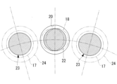
- FIG. 3 is a partial front view showing the relationship between recesses formed in the machined surface of FIG. 2 and fixing bolts for fixing the flange.
- FIG. 3 is a perspective view showing a state in which a draw bolt is fastened to a draw tap hole formed in the flange of FIG. 2
- FIG. 7 is a vertical cross-sectional view showing the relationship between the draw bolt and the recess in FIG. 6
- FIG. 4 is a diagram showing a modification of the recess in FIG. 3;
- An industrial machine 1 according to one embodiment of the present invention will be described below with reference to the drawings.
- An industrial machine 1 according to this embodiment is, for example, a robot, and as shown in FIG. 3.
- the housing 2 includes a first plate-like portion 4 and a second plate-like portion 5 formed in parallel flat plates.
- the first plate-like portion 4 and the second plate-like portion 5 are arranged to extend in the vertical direction in a state in which the industrial machine 1 is installed on an installation surface such as a horizontal floor.
- a processed surface A which is a plane extending in the vertical direction, is provided on the outer surface of the first plate-shaped portion 4 .
- the first plate-like portion 4 is provided with a first fitting hole (fitting hole) 6 extending from the processing surface A in a direction orthogonal to the processing surface A.
- the second plate-like portion 5 is provided with a second fitting hole 7 that is coaxial with the first fitting hole 6 and has an inner diameter smaller than that of the first fitting hole 6 .
- the shaft 3 is horizontally inserted into the first fitting hole 6 from the machined surface A side of the first plate-shaped part 4 , thereby forming a large-diameter portion 8 fitted in the first fitting hole 6 and a second fitting hole 6 .
- a small diameter portion 9 fitted in the fitting hole 7
- an intermediate portion 10 arranged between the large diameter portion 8 and the small diameter portion 9
- a flange 11 adjacent to the large diameter portion 8 .
- the intermediate portion 10 is fitted in the inner ring 13 of the bearing 12
- the outer ring 14 of the bearing 12 is fitted in the hole 16 provided at one end of the link member 15 .
- the shaft 3 is supported between the first plate-shaped portion 4 and the second plate-shaped portion 5 in a doubly supported beam-like manner, and the link member 15 is attached to the shaft 3 along the central axis O of the shaft 3. It is rotatably supported around a horizontal axis.
- the flange 11 is formed in a disc shape provided at one end of the large-diameter portion 8, and as shown in FIG. A through hole 17 is provided. Further, the flange 11 is provided with two extraction tap holes 18 at positions separated by 180° around the central axis O of the shaft 3 . Each extraction tap hole 18 is arranged at the same radial position about the central axis O of the shaft 3 between two circumferentially adjacent through holes 17 .
- the machined surface A is provided with a plurality of screw holes 19 arranged radially outward of the first fitting hole 6 at intervals in the circumferential direction. . Further, on the machined surface A, there are positions spaced apart by 180° around the central axis of the first fitting hole 6 and arranged above and below the horizontal line, for example, vertically above the first fitting hole 6 and two recesses 20 are provided at positions arranged vertically downward. Each recess 20 has a bottom surface 21a that is positioned one step lower than the processing surface A. As shown in FIG.
- the radius of the circle connecting the centers of the screw holes 19 of the machined surface A is the same as the radius of the circle connecting the centers of the through holes 17 of the flange 11 . Also, the distance from the central axis of the first fitting hole 6 to the recess 20 of the machined surface A is the same as the distance from the central axis O of the shaft 3 to the extraction tap hole 18 .
- each recess 20 is formed by a through hole 17 and a fixing bolt (bolt ) 23 and has a diameter D larger than the sum of the radial gap ⁇ .
- D ⁇ d+2 ⁇ meet the relationship.
- each recess 20 is a region around two screw holes 19 adjacent to each other in the circumferential direction. It is formed in a region that does not overlap with a circular region equal to the outer diameter of the .
- the shaft 3 in order to assemble the shaft 3 to the housing 2, the shaft 3 is processed into the first plate-shaped portion 4 while the bearing 12 is fitted to the intermediate portion 10 of the shaft 3. It is inserted horizontally into the first fitting hole 6 from the surface A side.
- the small-diameter portion 9 , the intermediate portion 10 , and the bearing 12 attached to the intermediate portion 10 are passed through the first fitting hole 6 .
- the small diameter portion 9 is fitted into the second fitting hole 7 of the second plate-shaped portion 5, the outer ring 14 of the bearing 12 is fitted into the hole 16 of the link member 15, and the large diameter portion 8 is fitted into the first plate-shaped portion. It fits into the first fitting hole 6 of the portion 4 .
- each through hole 17 of the flange 11 can be arranged at a position facing each screw hole 19 on the machined surface A, and the extraction tap hole 18 can be arranged at a position facing the recess 20 .
- the fixing bolts 23 passed through the through holes 17 are fastened to the screw holes 19 of the processed surface A while the flange 11 is in close contact with the processed surface A.
- the shaft 3 is fixed in a state of being supported between the two plate-like portions 4 and 5 of the housing 2, and the link member 15 is rotated around the central axis O of the shaft 3 with respect to the housing 2. can be supported as much as possible.
- the draw bolt 22 comes into contact with the bottom surface 21a of the recess 20 and presses it while rotating. Since the bottom surface 21a of the concave portion 20 is arranged at a position one step lower than the processing surface A, the burrs do not protrude outward from the processing surface A, so that the flange 11 and the processing surface A can be separated during the next assembly. without interfering with the adhesion of the In addition, there is no need to remove the generated burrs, and reassembly can be easily performed.
- the flange 11 cannot be machined.
- the surface A is displaced in the circumferential direction by the gap.
- the concave portion 20 is formed in a circular shape with a diameter larger than the dimension obtained by adding the dimension of the radial gap between the through-hole 17 and the fixing bolt 23 to the tip diameter dimension of the extraction bolt 22 fastened to the extraction tap hole 18 . Therefore, even if the flange 11 is displaced in the circumferential direction, the tip surface of the draw bolt 22 can be arranged in the recess 20 .
- the tapped hole 18 is arranged on the opposite side of the shaft 3 with respect to the central axis O. Therefore, by alternately tightening the two draw bolts 22 little by little, galling can be prevented. The shaft 3 can be pulled out from the first fitting hole 6 without any effort.
- the weight of the link member 15 or a member connected to the link member 15 causes an intermediate
- the portion 10 may be loaded upwards or downwards.
- a moment around the horizontal axis is generated in the shaft 3, but by applying a moment in the opposite direction by the pull-out bolts 22 above and below the large diameter portion 8, the shaft 3 can be moved while correcting galling. There is an advantage that it can be pulled out easily.
- the recess 20 is formed in a circular shape with a diameter larger than the sum of the outer diameter of the tip of the draw bolt 22 and the radial gap between the through hole 17 and the fixing bolt 23.
- the tip of the pull-out bolt 22 may be placed in the recess 20. Therefore, as shown in FIG. may be formed in an oval shape extending in the circumferential direction.
- the width dimension in the radial direction with respect to the center of the first fitting hole 6 should be slightly larger than the tip diameter of the draw bolt 22 .
- two recesses 20 are provided vertically above and below the first fitting hole 6, but the present invention is not limited to this. As long as they are arranged above and below a horizontal line that passes through the central axis of the first fitting hole 6 and is arranged on the processing surface A, they may be deviated from the vertically upward or vertically downward direction.
- the housing 2 may be provided with an identification mark that enables identification of the position of the concave portion 20 when the flange 11 is in close contact with the processing surface A.
- FIG. Examples of the identification mark provided on the processing surface A include attaching a mark arranged on the bottom surface 21a of the recess 20, or coloring only the bottom surface 21a of the recess 20, and the like.
- the identification display can be confirmed through the extraction tap hole 18, and the extraction bolt 22 is prevented from pressing the machined surface A other than the recess 20.
- the identification display may be a mark such as an arrow that is arranged radially outward of the flange 11 brought into close contact with the processing surface A and indicates the position of the recess 20 .
- the housing 2 and the shaft 3 as the mechanical parts are exemplified by rotatably attaching the link member 15 to the housing 2, but the present invention is not limited to this, and other It can be applied to any mechanical part.
- a robot is illustrated as the industrial machine 1, it may be applied to any other industrial machine instead.
Landscapes
- Engineering & Computer Science (AREA)
- General Engineering & Computer Science (AREA)
- Mechanical Engineering (AREA)
- Connection Of Plates (AREA)
- Manipulator (AREA)
Priority Applications (6)
| Application Number | Priority Date | Filing Date | Title |
|---|---|---|---|
| JP2024502735A JP7733208B2 (ja) | 2022-02-28 | 2022-02-28 | 産業機械 |
| DE112022005568.5T DE112022005568T5 (de) | 2022-02-28 | 2022-02-28 | Industriemaschine |
| US18/833,286 US20250154988A1 (en) | 2022-02-28 | 2022-02-28 | Industrial machine |
| CN202280092205.XA CN118765353A (zh) | 2022-02-28 | 2022-02-28 | 工业机械 |
| PCT/JP2022/008251 WO2023162215A1 (ja) | 2022-02-28 | 2022-02-28 | 産業機械 |
| TW112105445A TW202335768A (zh) | 2022-02-28 | 2023-02-15 | 産業機械 |
Applications Claiming Priority (1)
| Application Number | Priority Date | Filing Date | Title |
|---|---|---|---|
| PCT/JP2022/008251 WO2023162215A1 (ja) | 2022-02-28 | 2022-02-28 | 産業機械 |
Publications (1)
| Publication Number | Publication Date |
|---|---|
| WO2023162215A1 true WO2023162215A1 (ja) | 2023-08-31 |
Family
ID=87765160
Family Applications (1)
| Application Number | Title | Priority Date | Filing Date |
|---|---|---|---|
| PCT/JP2022/008251 Ceased WO2023162215A1 (ja) | 2022-02-28 | 2022-02-28 | 産業機械 |
Country Status (6)
| Country | Link |
|---|---|
| US (1) | US20250154988A1 (https=) |
| JP (1) | JP7733208B2 (https=) |
| CN (1) | CN118765353A (https=) |
| DE (1) | DE112022005568T5 (https=) |
| TW (1) | TW202335768A (https=) |
| WO (1) | WO2023162215A1 (https=) |
Citations (7)
| Publication number | Priority date | Publication date | Assignee | Title |
|---|---|---|---|---|
| JPS5983105U (ja) * | 1982-11-27 | 1984-06-05 | 株式会社神崎高級工機製作所 | アルミ製ケ−ス |
| JPS6416380A (en) * | 1987-07-08 | 1989-01-19 | Toshiba Corp | Mating face separator |
| JPH0398332U (https=) * | 1990-01-29 | 1991-10-11 | ||
| JP2003305665A (ja) * | 2002-04-11 | 2003-10-28 | Keizo Otori | フランジ間隔拡張治具並びに拡張機能付きフランジ及びフランジ間隔拡張方法 |
| JP2004092115A (ja) * | 2002-08-30 | 2004-03-25 | Komatsu Ltd | ピン組立体及び作業機連結装置 |
| JP2005201122A (ja) * | 2004-01-14 | 2005-07-28 | Ishikawajima Harima Heavy Ind Co Ltd | 機械部品における分離構造、エンジンケース部品における分離構造、及びエンジンケース |
| JP2013126297A (ja) * | 2011-12-14 | 2013-06-24 | Denso Corp | 電力変換装置 |
-
2022
- 2022-02-28 JP JP2024502735A patent/JP7733208B2/ja active Active
- 2022-02-28 US US18/833,286 patent/US20250154988A1/en active Pending
- 2022-02-28 WO PCT/JP2022/008251 patent/WO2023162215A1/ja not_active Ceased
- 2022-02-28 DE DE112022005568.5T patent/DE112022005568T5/de active Pending
- 2022-02-28 CN CN202280092205.XA patent/CN118765353A/zh active Pending
-
2023
- 2023-02-15 TW TW112105445A patent/TW202335768A/zh unknown
Patent Citations (7)
| Publication number | Priority date | Publication date | Assignee | Title |
|---|---|---|---|---|
| JPS5983105U (ja) * | 1982-11-27 | 1984-06-05 | 株式会社神崎高級工機製作所 | アルミ製ケ−ス |
| JPS6416380A (en) * | 1987-07-08 | 1989-01-19 | Toshiba Corp | Mating face separator |
| JPH0398332U (https=) * | 1990-01-29 | 1991-10-11 | ||
| JP2003305665A (ja) * | 2002-04-11 | 2003-10-28 | Keizo Otori | フランジ間隔拡張治具並びに拡張機能付きフランジ及びフランジ間隔拡張方法 |
| JP2004092115A (ja) * | 2002-08-30 | 2004-03-25 | Komatsu Ltd | ピン組立体及び作業機連結装置 |
| JP2005201122A (ja) * | 2004-01-14 | 2005-07-28 | Ishikawajima Harima Heavy Ind Co Ltd | 機械部品における分離構造、エンジンケース部品における分離構造、及びエンジンケース |
| JP2013126297A (ja) * | 2011-12-14 | 2013-06-24 | Denso Corp | 電力変換装置 |
Also Published As
| Publication number | Publication date |
|---|---|
| DE112022005568T5 (de) | 2024-09-05 |
| TW202335768A (zh) | 2023-09-16 |
| CN118765353A (zh) | 2024-10-11 |
| JP7733208B2 (ja) | 2025-09-02 |
| JPWO2023162215A1 (https=) | 2023-08-31 |
| US20250154988A1 (en) | 2025-05-15 |
Similar Documents
| Publication | Publication Date | Title |
|---|---|---|
| CN102102696B (zh) | 带有耳状外扩部的螺母 | |
| EP1052424B1 (en) | Apparatus and methods for balancing turbine rotors | |
| EP3293860A1 (en) | Rotary electric rotor and method of manufacturing rotary electric rotor | |
| KR101067739B1 (ko) | 설치부재 위치 결정장치 | |
| RU2426889C2 (ru) | Устройство для осевого удержания фланца диска ротора, а также турбина турбомашины и турбомашина, содержащие такое устройство | |
| JP2005308223A (ja) | カラーを有するピンを用いて部品をともに締め付けるためのファスナシステム | |
| EP3156675B1 (en) | Bearing device and method for manufacturing bearing device | |
| JP2004034157A (ja) | 圧延機のロールアセンブリ | |
| WO2023162215A1 (ja) | 産業機械 | |
| EP3196491B1 (en) | Bearing device and method for manufacturing bearing device | |
| JP4965109B2 (ja) | プーリ | |
| JP2004526107A (ja) | 先細りころ軸受組立体を形成する方法 | |
| JP4326191B2 (ja) | ピン型保持器 | |
| JP6512009B2 (ja) | 締結装置 | |
| CN112039275A (zh) | 平衡板组件 | |
| CN108026981A (zh) | 具有转矩传递板的(双)离合器、包括离合器和工具的系统和用于平衡离合器的方法 | |
| US12359755B2 (en) | Pipe joint, spacer provided in pipe joint, and dividing piece constituting spacer | |
| US6435758B1 (en) | Connection arrangement for coupling a hydrodynamic torque converter to a rotating shaft | |
| US11835093B2 (en) | Clamp collar | |
| JP2024522680A (ja) | バンプフォイルの離脱を防止するジャーナルフォイル空気軸受 | |
| JP2000179563A (ja) | 軸継手の軸締結装置 | |
| US12565913B2 (en) | Roller bearing for supporting wheel | |
| JP7681921B2 (ja) | トップフォイルの離脱を防止するジャーナルフォイル空気軸受 | |
| US12338799B2 (en) | System for repositioning two components of a wind turbine with respect to each other | |
| US20250207636A1 (en) | Removable bearing holder |
Legal Events
| Date | Code | Title | Description |
|---|---|---|---|
| 121 | Ep: the epo has been informed by wipo that ep was designated in this application |
Ref document number: 22928741 Country of ref document: EP Kind code of ref document: A1 |
|
| ENP | Entry into the national phase |
Ref document number: 2024502735 Country of ref document: JP Kind code of ref document: A |
|
| WWE | Wipo information: entry into national phase |
Ref document number: 112022005568 Country of ref document: DE |
|
| WWE | Wipo information: entry into national phase |
Ref document number: 18833286 Country of ref document: US |
|
| WWE | Wipo information: entry into national phase |
Ref document number: 202280092205.X Country of ref document: CN |
|
| 122 | Ep: pct application non-entry in european phase |
Ref document number: 22928741 Country of ref document: EP Kind code of ref document: A1 |
|
| WWP | Wipo information: published in national office |
Ref document number: 18833286 Country of ref document: US |