WO2023161986A1 - ひずみ検出装置 - Google Patents
ひずみ検出装置 Download PDFInfo
- Publication number
- WO2023161986A1 WO2023161986A1 PCT/JP2022/007188 JP2022007188W WO2023161986A1 WO 2023161986 A1 WO2023161986 A1 WO 2023161986A1 JP 2022007188 W JP2022007188 W JP 2022007188W WO 2023161986 A1 WO2023161986 A1 WO 2023161986A1
- Authority
- WO
- WIPO (PCT)
- Prior art keywords
- tire
- strain
- inner peripheral
- recess
- housing
- Prior art date
- Legal status (The legal status is an assumption and is not a legal conclusion. Google has not performed a legal analysis and makes no representation as to the accuracy of the status listed.)
- Ceased
Links
Images
Classifications
-
- B—PERFORMING OPERATIONS; TRANSPORTING
- B60—VEHICLES IN GENERAL
- B60C—VEHICLE TYRES; TYRE INFLATION; TYRE CHANGING; CONNECTING VALVES TO INFLATABLE ELASTIC BODIES IN GENERAL; DEVICES OR ARRANGEMENTS RELATED TO TYRES
- B60C23/00—Devices for measuring, signalling, controlling, or distributing tyre pressure or temperature, specially adapted for mounting on vehicles; Arrangement of tyre inflating devices on vehicles, e.g. of pumps or of tanks; Tyre cooling arrangements
- B60C23/02—Signalling devices actuated by tyre pressure
- B60C23/04—Signalling devices actuated by tyre pressure mounted on the wheel or tyre
-
- B—PERFORMING OPERATIONS; TRANSPORTING
- B60—VEHICLES IN GENERAL
- B60C—VEHICLE TYRES; TYRE INFLATION; TYRE CHANGING; CONNECTING VALVES TO INFLATABLE ELASTIC BODIES IN GENERAL; DEVICES OR ARRANGEMENTS RELATED TO TYRES
- B60C23/00—Devices for measuring, signalling, controlling, or distributing tyre pressure or temperature, specially adapted for mounting on vehicles; Arrangement of tyre inflating devices on vehicles, e.g. of pumps or of tanks; Tyre cooling arrangements
- B60C23/06—Signalling devices actuated by deformation of the tyre, e.g. tyre mounted deformation sensors or indirect determination of tyre deformation based on wheel speed, wheel-centre to ground distance or inclination of wheel axle
- B60C23/064—Signalling devices actuated by deformation of the tyre, e.g. tyre mounted deformation sensors or indirect determination of tyre deformation based on wheel speed, wheel-centre to ground distance or inclination of wheel axle comprising tyre mounted deformation sensors, e.g. to determine road contact area
-
- B—PERFORMING OPERATIONS; TRANSPORTING
- B60—VEHICLES IN GENERAL
- B60C—VEHICLE TYRES; TYRE INFLATION; TYRE CHANGING; CONNECTING VALVES TO INFLATABLE ELASTIC BODIES IN GENERAL; DEVICES OR ARRANGEMENTS RELATED TO TYRES
- B60C19/00—Tyre parts or constructions not otherwise provided for
-
- B—PERFORMING OPERATIONS; TRANSPORTING
- B60—VEHICLES IN GENERAL
- B60C—VEHICLE TYRES; TYRE INFLATION; TYRE CHANGING; CONNECTING VALVES TO INFLATABLE ELASTIC BODIES IN GENERAL; DEVICES OR ARRANGEMENTS RELATED TO TYRES
- B60C23/00—Devices for measuring, signalling, controlling, or distributing tyre pressure or temperature, specially adapted for mounting on vehicles; Arrangement of tyre inflating devices on vehicles, e.g. of pumps or of tanks; Tyre cooling arrangements
- B60C23/02—Signalling devices actuated by tyre pressure
- B60C23/04—Signalling devices actuated by tyre pressure mounted on the wheel or tyre
- B60C23/0491—Constructional details of means for attaching the control device
- B60C23/0493—Constructional details of means for attaching the control device for attachment on the tyre
Definitions
- the present disclosure relates to a strain detection device.
- Functional parts that can be attached to tires have long been known.
- the functional parts described in Patent Document 1 below contain electronic parts capable of acquiring tire information, can be attached to the inner peripheral surface of the tire, and include a housing portion, a housing, strain detection means, and a support portion. and an elastic portion (summary, etc.).
- the storage section stores electronic components.
- the housing has a bottom surface facing the inner circumferential surface of the tire.
- the strain detection means is provided on the bottom surface of the housing and detects tire strain.
- the support portion extends from the bottom surface of the housing toward the inner peripheral surface of the tire and protrudes from the surface of the strain detection means.
- the elastic portion is made of an elastomer having lower rigidity than the material forming the support portion, and is interposed between the bottom surface of the housing and the inner peripheral surface of the tire.
- the support portion can support the functional component even if the centrifugal force due to the rotation of the tire acts on the functional component.
- the distance between the inner surface of the tire and the strain detecting means can be kept constant, and variations in the detection accuracy of the strain detecting means can be reduced (Patent Document 1, paragraph 0005, etc.).
- the functional component described in Patent Document 2 below contains an electronic component that can acquire information in the tire, and can be attached to the inner peripheral surface of the tire. (abstract, etc.).
- the housing has an electronic component housing portion and a bottom surface facing the inner peripheral surface of the tire, and the tubular portion extends from the periphery of the bottom surface of the housing toward the inner peripheral surface of the tire.
- a container having one opening formed by the housing and the tubular portion extending from the peripheral edge of the bottom surface of the housing toward the inner peripheral surface of the tire is filled with the adhesive, and the tubular portion side is filled.
- the adhesive is allowed to cure.
- the functional component can be adhered to the inner surface of the tire while ensuring the thickness of the adhesive (Patent Document 2, paragraph 0005).
- JP 2021-146875 A Japanese Patent Application Laid-Open No. 2020-055402
- the housing is made of synthetic resin or the like from the viewpoint of weight reduction and strength (paragraph 0011). Therefore, the support portion extending from the bottom surface of the housing toward the inner peripheral surface of the tire becomes harder than the tire, and deformation of the tire is hindered by the support portion in contact with the inner peripheral surface of the tire, and the detection accuracy of the strain detection means. may decrease.
- the material of the skirt as the cylindrical portion is an elastic or flexible material made of rubber, elastomer, or the like (paragraphs 0010 and 0021).
- the cylindrical portion deforms to follow the strain of the tire, so tire deformation is not hindered and deterioration in the detection accuracy of the strain sensor can be suppressed. Desired.
- the present disclosure provides a strain detection device that does not hinder deformation of the tire and that can be made more compact and improve strain detection accuracy than the above-described conventional functional parts.
- One aspect of the present disclosure includes a housing bonded to the inner peripheral surface of a tire via an elastic adhesive, a recess provided in an end surface of the housing facing the inner peripheral surface of the tire, and the recess a strain detecting element for detecting strain of the tire via the elastic adhesive; and an elastic member protruding toward the peripheral surface, wherein the elastic adhesive is filled in a space between the bottom surface of the recess and the inner peripheral surface of the tire inside the elastic member. It is a strain detector that
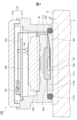
- FIG. 1 is an enlarged cross-sectional view showing an embodiment of a strain detection device according to the present disclosure
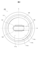
- FIG. FIG. 2 is a bottom view of the strain detector of FIG. 1
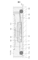
- FIG. 2 is an enlarged view of part III surrounded by a rectangular dashed line in FIG. 1 ;
- FIG. 1 is an enlarged cross-sectional view showing an embodiment of a strain detection device according to the present disclosure.
- FIG. 2 is a bottom view of the strain detection device 100 of FIG.
- the strain detection device 100 of the present embodiment is attached, for example, to the inner peripheral surface Ti of a tire T of a vehicle such as an automobile, detects the strain of the tire T, and transmits the detection result to a vehicle control device mounted on the vehicle by wireless communication. It is a device that transmits to an external device such as a device.
- the strain detection device 100 of this embodiment mainly includes a housing 110, a strain detection element 120, and an elastic member . Moreover, in the example shown in FIG. 1 , the strain detection device 100 further includes a battery 140 and a circuit board 150 . Hereinafter, each part of the strain detection device 100 of this embodiment will be described in detail.
- the housing 110 is, for example, a bottomed tubular member that houses components such as the battery 140 and the circuit board 150, and is adhered to the inner peripheral surface Ti of the tire T via the elastic adhesive EA.
- the hardness of the elastic adhesive EA after curing is equivalent to that of the tire T.
- the elastic adhesive EA has elasticity that allows it to elastically deform, for example, following deformation of the tire T during running of the vehicle.
- the housing 110 is, for example, a synthetic resin molding harder than the tire T.
- the housing 110 has, for example, a cylindrical shape in which the diameter of the upper end located on the center side of the tire T is larger than the diameter of the lower end adjacent to the inner peripheral surface Ti of the tire T. As shown in FIG.
- the shape of the housing 110 is not limited to a cylindrical shape, and any shape such as an elliptical cylindrical shape, a rectangular cylindrical shape, or a polygonal cylindrical shape can be adopted.
- the housing 110 has, for example, a bottomed tubular main body 111 having an opening, and a flat plate-like lid 112 that closes the opening of the main body 111 .
- a recessed groove with which the peripheral edge portion of the lid portion 112 is engaged is provided.
- the peripheral edge portion of the lid portion 112 is provided so as to protrude toward the inner peripheral surface Ti of the tire T in the radial direction of the tire T, which is the height direction of the strain detection device 100, and the upper end portion of the main body portion 111. It engages with the groove.
- Lid portion 112 is bonded to body portion 111 by, for example, an adhesive, and seals the opening of body portion 111 .
- FIG. 3 is an enlarged view of part III surrounded by the dashed line in FIG.
- a concave portion 111c is provided in an end surface 111e of the lower end portion of the main body portion 111, which faces the inner peripheral surface Ti of the tire T. As shown in FIG.
- the concave portion 111c is provided, for example, in a portion of the end surface 111e of the body portion 111 excluding the peripheral edge portion.
- a convex portion is provided on the peripheral edge portion of the end surface of the main body portion 111 facing the inner peripheral surface Ti of the tire T, and the tip surface of the convex portion is provided on the end surface.
- 111e, and the inner side of the protrusion may be the recess 111c.
- the convex portion around the concave portion 111c may be continuous over the entire circumference of the concave portion 111c, or may be provided partially around the concave portion 111c.
- the recess 111c provided in the end surface 111e of the main body 111 has, for example, a bottom surface 111b perpendicular to the height direction of the strain detection device 100 and an inner peripheral wall 111w parallel to the height direction of the strain detection device 100.
- the inner peripheral wall 111w is provided, for example, continuously over the entire circumference of the bottom surface 111b.
- the elastic member 130 is arranged on the outer edge of the bottom surface 111b of the recess 111c, and the holding recess 111r for holding the strain detection element 120 is provided in the center of the bottom surface 111b of the recess 111c.
- the strain detection element 120 is a device that is arranged in the center of the recess 111c provided in the end surface 111e of the main body 111 and detects the strain of the tire T via the elastic adhesive EA.
- Strain detection element 120 includes, for example, flat support member 121 and semiconductor sensor 122 .
- the strain detection element 120 includes, for example, wiring 123 and an elastic support member 124 .
- the support member 121 is supported by the bottom surface 111b of the recess 111c of the housing 110 and faces the inner peripheral surface Ti of the tire T via the elastic adhesive EA. More specifically, the support member 121 is adhered to, for example, an end surface of an elastic support member 124 held in a holding recess 111r provided in the central portion of the bottom surface 111b of the recess 111c. It is supported by the bottom surface 111b of 111c.
- the support member 121 is, for example, a thin metal plate such as stainless steel having a thickness of about 0.3 mm.
- the lower surface of the support member 121 facing the inner peripheral surface Ti of the tire T via the elastic adhesive EA is, for example, a flat surface without unevenness.
- the semiconductor sensor 122 is provided on the upper surface of the support member 121 opposite to the lower surface facing the inner peripheral surface Ti of the tire T.
- Semiconductor sensor 122 is, for example, a square semiconductor chip. Note that the shape of the semiconductor chip is not limited to a square, and may be circular, elliptical, or any other shape.
- the semiconductor sensor 122 uses, for example, the piezoresistive effect of a diffused resistor formed by ion-implanting impurities into a silicon single crystal, and measures the strain of the tire T by directly measuring the voltage from the electrode pad of the semiconductor chip. can be detected. More specifically, the semiconductor sensor 122 detects the strain of the tire T by detecting the strain of the support member 121 that deforms following the deformation of the tire T, for example.
- the semiconductor sensor 122 is, for example, a semiconductor sensor for biaxial strain measurement that detects strain in two directions orthogonal to each other.
- the semiconductor sensor 122 measures strain components in the X-axis direction, which is the circumferential direction of the tire T, that is, the rotational direction, and the Y-axis direction, which is the width direction of the tire T, as shown in FIG. Therefore, the semiconductor sensor 122 has two bridge circuits of diffused resistors in one sensor chip, and the strain components in each direction are calculated from the output values of these bridge circuits.
- the two bridge circuits that can detect strain in two directions orthogonal to each other include, for example, two types of diffused resistors: a high-sensitivity diffused resistor with high strain sensitivity and a low-sensitivity diffused resistor with low strain sensitivity. It is a bridge circuit in which two wires are combined. Then, as the highly sensitive resistor, a diffused resistor having a large difference in absolute value of strain sensitivity in the direction parallel to the current and in the direction perpendicular to the current is used. This makes it possible to increase the difference between the absolute values of the strain sensitivities in the longitudinal direction and the lateral direction in the two bridge circuits, making it possible to measure strain in two directions perpendicular to each other.
- Wiring 123 connects the semiconductor sensor 122 and the circuit board 150, for example.
- Wiring 123 includes, for example, a power supply line that supplies power from circuit board 150 to semiconductor sensor 122 and a signal line that transmits a signal output from semiconductor sensor 122 to circuit board 150 .
- the wiring 123 is pulled out from the semiconductor sensor 122, passed through a through hole provided in the bottom wall of the body portion 111 of the housing 110, and connected to the connector 151 of the circuit board 150 accommodated in the housing 110.
- the elastic support member 124 has, for example, a recess forming a space for housing the semiconductor sensor 122, and the support member 121 is adhered to the end face provided with the recess.
- the end face of the elastic support member 124 opposite to the end face to which the support member 121 is adhered is adhered to the holding recess 111r provided in the central portion of the recess 111c of the body portion 111, for example, with an adhesive.
- an elastic material having hardness equivalent to that of the tire T such as silicone rubber, can be used.
- the elastic support member 124 for example, absorbs vibration and shock acting on the strain detection element 120, and protects the semiconductor sensor 122 from vibration and shock.
- the elastic member 130 is arranged on the inner peripheral edge of the recessed portion 111c provided in the body portion 111 of the housing 110, and protrudes from the end face 111e of the body portion 111 toward the inner peripheral surface Ti of the tire T. Then, inside the elastic member 130, the space between the bottom surface 111b of the concave portion 111c of the main body portion 111 and the inner peripheral surface Ti of the tire T is filled with the elastic adhesive EA.
- a gap is formed between the end surface 111e of the body portion 111 of the housing 110 and the inner peripheral surface Ti of the tire T.
- a gap G is formed.
- the height at which the elastic member 130 protrudes from the end surface 111e of the main body portion 111 is, for example, to avoid contact between the inner peripheral surface Ti of the tire T and the housing 110 when the tire T is deformed. It is determined according to the possible height of the gap G.
- the elastic member 130 has, for example, an annular shape as shown in FIG. ing. 1 and 3, the elastic member 130 has a circular cross-sectional shape along the radial direction of the annular elastic member 130. As shown in FIG.
- the shape of the elastic member 130 is not limited to an annular shape.
- the shape of the elastic member 130 may be, for example, an oblong shape that matches the oblong support member 121 of the strain sensing element 120, as shown in FIG.
- the shape of the elastic member 130 can be a shape similar to the shape of the semiconductor chip of the semiconductor sensor 122, such as a square. In these cases, the shape of the concave portion 111c of the main body portion 111 is also changed according to the shape of the elastic member 130.
- FIG. Also, the cross-sectional shape of the cross section of the elastic member 130 is not limited to a circular shape.
- the cross-sectional shape of the cross section of the elastic member 130 may be, for example, an ellipse, a square, a D shape with a semicircular outer peripheral side, or other shapes.
- the outer edge of the elastic member 130 is engaged with the inner peripheral wall 111w of the recessed portion 111c provided in the body portion 111 of the housing 110 . That is, the annular elastic member 130 is, for example, fitted inside the inner peripheral wall 111w of the recess 111c in a state of being elastically deformed radially inward. Accordingly, the outer edge of the elastic member 130 is pressed against the inner peripheral wall 111w of the recess 111c by the elastic force of the elastic member 130. As shown in FIG.
- the material of the elastic member 130 is, for example, an elastic material such as rubber similar to the material of the tire T.
- the elastic member 130 has hardness equivalent to that of the tire T, for example.
- the hardness of the elastic member 130 is, for example, about 50 to 80 in Shore A durometer hardness.
- the elastic member 130 and the housing 110 may be separate members that are individually molded, or may be one member that is integrally molded.
- Battery 140 is, for example, a button-type battery, which is accommodated inside body portion 111 through an opening of body portion 111 of housing 110, and is arranged and held in a recess provided in the bottom wall of body portion 111. there is Battery 140 , for example, is connected to circuit board 150 via connection terminal 141 and supplies power to circuit board 150 .
- the circuit board 150 is accommodated, for example, inside the opening of the main body 111 of the housing 110 and arranged on the battery 140 .
- the peripheral portion of circuit board 150 is fixed to, for example, a stepped portion inside the opening of main body portion 111 .
- the circuit board 150 has, for example, a connector 152 to which the wiring 123 of the strain detection element 120 is connected, supplies electric power to the strain detection element 120, and receives the strain detection result of the tire T from the strain detection element 120. .
- the circuit board 150 includes, for example, a power supply circuit, a signal processing circuit, a wireless communication circuit, and a control circuit.
- the power supply circuit supplies power supplied from the battery 140 to the strain detection element 120, for example.
- the signal processing circuit processes signals input from the strain detection element 120, for example.
- the wireless communication circuit for example, transmits the strain detection result of the tire T by the strain detection element 120 to an external device by wireless communication.
- the control circuit controls, for example, a power supply circuit, a signal processing circuit, and a wireless communication circuit.
- strain detection device 100 of this embodiment will be described below based on a comparison with the conventional technology.
- the housing is made of synthetic resin or the like from the viewpoint of weight reduction and strength (paragraph 0011). Therefore, the support portion extending from the bottom surface of the housing toward the inner peripheral surface of the tire becomes harder than the tire, and deformation of the tire is hindered by the support portion in contact with the inner peripheral surface of the tire, and the detection accuracy of the strain detection means. may decrease.
- the material of the skirt as the cylindrical portion is an elastic material or flexible material such as rubber or elastomer (paragraphs 0010 and 0021).
- the cylindrical portion deforms to follow the strain of the tire, so tire deformation is not hindered and deterioration in the detection accuracy of the strain sensor can be suppressed. Desired.
- the skirt is attached to the skirt mounting portion on the outer peripheral surface of the storage case (paragraph 0017, FIG. 4, etc.).
- the skirt includes an annular cylindrical portion and an enlarged portion extending from the cylindrical portion toward the inner peripheral surface of the tire (paragraph 0018, FIG. 4, etc.).
- the enlarged portion is formed in a widening shape continuous from the tubular portion.
- the inner peripheral surface of the enlarged portion is formed as a curved surface that gradually expands in diameter from the outer peripheral edge of the outer bottom surface of the storage case toward the inner peripheral surface side of the tire in an axial cross section (Paragraph 0019, FIG. 4, etc.).
- the outer diameter of the enlarged portion of the skirt becomes larger than the outer diameter of the storage case, which not only increases the size of the functional parts, but also increases the amount of adhesive that fills the inside of the skirt.
- the thickness of the inner peripheral surface and the outer peripheral surface forming the enlarged portion is set in a tapered shape so that it gradually becomes thinner toward the axial end portion on the inner peripheral surface side of the tire (paragraph 0020, FIG. 4).
- the strain detection device 100 of the present embodiment includes a housing 110 bonded to the inner peripheral surface Ti of the tire T via the elastic adhesive EA, and a housing 110 facing the inner peripheral surface Ti of the tire T. and a recess 111c provided in the end face 111e of the.
- the strain detection device 100 includes a strain detection element 120 that is arranged in the center of the recess 111c and detects the strain of the tire T via the elastic adhesive EA, and a housing that is arranged in the inner periphery of the recess 111c. and an elastic member 130 that protrudes toward the inner peripheral surface Ti of the tire T from the end surface 111e of the tire 110 .
- the space between the bottom surface 111b of the recess 111c and the inner peripheral surface Ti of the tire T inside the elastic member 130 is filled with the elastic adhesive EA.
- the strain detection device 100 is configured such that the housing 110 is adhered to the inner peripheral surface Ti of the tire T via the elastic adhesive EA, and the elastic member 130 and the elastic member 130 filled in the space inside thereof. It will be in contact with the tire T via the adhesive EA. Accordingly, when the tire T is elastically deformed, the elastic member 130 having hardness equivalent to that of the tire T and the elastic adhesive EA are elastically deformed following the elastic deformation of the tire T, for example.
- a gap G is formed between the end surface 111e of the housing 110 and the inner peripheral surface Ti of the tire T by the elastic member 130 projecting from the end surface 111e of the housing 110 toward the inner peripheral surface Ti of the tire T. be. Accordingly, it is possible to prevent the elastic deformation of the tire T from being hindered by the housing 110 of the strain detection device 100, and to improve the detection accuracy of the strain of the tire T by the strain detection element 120. FIG. In addition, since the elastic member 130 and the elastic adhesive EA are elastically deformed following the elastic deformation of the tire T, concentration of stress on the elastic adhesive EA is prevented. Detachment from the surface Ti can be prevented.
- the strain detecting element 120 and the inner peripheral surface Ti of the tire T are filled into the elastic adhesive EA in the space between the bottom surface 111b of the recess 111c and the inner peripheral surface Ti of the tire T inside the elastic member 130, the strain detecting element 120 and the inner peripheral surface Ti of the tire T The thickness of the elastic adhesive EA between becomes uniform. As a result, the distribution of strain detected by the strain detection element 120 through the elastic adhesive EA becomes uniform, and the strain detection sensitivity of the strain detection element 120 to the strain of the tire T through the elastic adhesive EA becomes uniform. Therefore, the strain detection accuracy of the tire T by the strain detection element 120 can be improved.
- the strain detection device 100 can arrange the elastic member 130 inside the recess 111c provided in the end surface 111e of the housing 110 facing the inner peripheral surface Ti of the tire T. Therefore, in the strain detection device 100 of the present embodiment, the skirt extending from the peripheral edge of the bottom surface of the housing toward the inner peripheral surface of the tire like the functional component described in Patent Document 2 has an enlarged portion. Therefore, miniaturization becomes possible. Further, according to the strain detection device 100 of the present embodiment, it is possible to reduce the amount of elastic adhesive EA used and reduce the material cost as compared with the functional component described in Patent Document 2.
- the elastic member 130 has an annular shape.
- the strain detection element 120 includes a biaxial strain measurement semiconductor sensor 122 that detects strain in two directions perpendicular to each other, and is arranged at the center of the annular elastic member 130 .
- the strain detection device 100 of the present embodiment uniformly detects the strain of the tire T in all radial directions of the annular elastic member 130 by the strain detection element 120 via the elastic adhesive EA. can do.
- the deformation state of the tire T can be more accurately detected by the strain detection element 120, and information such as unevenness of the road surface on which the vehicle is traveling can be more accurately grasped.
- the cross-sectional shape of the elastic member 130 is circular.
- the strain detection device 100 of the present embodiment makes contact between the elastic member 130 and the bottom surface 111b and the inner peripheral wall 111w of the recessed portion 111c of the housing 110 and contact with the inner peripheral surface Ti of the tire T. can be brought into contact.
- the elastic member 130 can be stably supported by the bottom surface 111b and the inner peripheral wall 111w at the inner periphery of the recess 111c.
- the height of the elastic member 130 between them is made uniform in the circumferential direction of the elastic member 130.
- the thickness of the elastic adhesive EA between the bottom surface 111b of the recess 111c and the inner peripheral surface Ti of the tire T can be made uniform, and the strain detection accuracy of the strain detector 100 can be improved.
- the cross-sectional shape of the elastic member 130 is elliptical, the compressive strength in the longitudinal direction of the elliptical cross-section can be improved.
- the outer edge of the elastic member 130 is engaged with the inner peripheral wall 111w of the recess 111c.
- the strain detector 100 of the present embodiment can support the outer edge of the elastic member 130 by the inner peripheral wall 111w of the recess 111c and hold the elastic member 130 inside the recess 111c. Therefore, there is no need to provide a convex portion for engaging the elastic member 130 with the bottom surface 111b of the concave portion 111c inside the elastic member 130, and the strain detection accuracy of the strain detecting element 120 is prevented from deteriorating due to the convex portion harder than the tire T. can be prevented.
- the strain detection element 120 includes a flat support member 121 and a semiconductor sensor 122 .
- the support member 121 is supported by the bottom surface 111b of the recess 111c of the housing 110 and faces the inner peripheral surface Ti of the tire T via the elastic adhesive EA.
- the semiconductor sensor 122 is provided on the surface of the support member 121 opposite to the surface facing the inner peripheral surface Ti of the tire T. As shown in FIG.
- the strain detecting device 100 of the present embodiment can make the surface of the support member 121 facing the inner peripheral surface Ti of the tire T a flat surface without unevenness.
- a protrusion that is harder than the tire T is not formed on the surface of the support member 121 facing the inner peripheral surface Ti of the tire T, and the strain detection accuracy of the strain detection element 120 can be prevented from deteriorating.
- the semiconductor sensor 122 can detect the strain of the tire T with high accuracy through the elastic adhesive EA having a uniform thickness and the flat support member 121 .
- strain detector 110 housing 111 main body (housing) 111b Bottom surface 111c Recess 111e End surface 111w Inner peripheral wall 112 Lid (housing) 120 strain detection element 121 support member 122 semiconductor sensor (semiconductor sensor for biaxial strain measurement) 130 elastic member EA elastic adhesive T tire Ti inner peripheral surface
Landscapes
- Engineering & Computer Science (AREA)
- Mechanical Engineering (AREA)
- Tires In General (AREA)
- Measurement Of Length, Angles, Or The Like Using Electric Or Magnetic Means (AREA)
Abstract
Description
110 筐体
111 本体部(筐体)
111b 底面
111c 凹部
111e 端面
111w 内周壁
112 蓋部(筐体)
120 ひずみ検出素子
121 支持部材
122 半導体センサ(2軸ひずみ計測用半導体センサ)
130 弾性部材
EA 弾性接着剤
T タイヤ
Ti 内周面
Claims (5)
- タイヤの内周面に弾性接着剤を介して接着される筐体と、
前記タイヤの前記内周面に対向する前記筐体の端面に設けられた凹部と、
前記凹部の中央部に配置されて前記弾性接着剤を介して前記タイヤのひずみを検出するひずみ検出素子と、
前記凹部の内側の周縁部に配置されて前記筐体の前記端面よりも前記タイヤの前記内周面へ向けて突出する弾性部材と、を備え、
前記弾性部材の内側で前記凹部の底面と前記タイヤの前記内周面との間の空間に前記弾性接着剤が充填されることを特徴とするひずみ検出装置。 - 前記弾性部材は、円環形状を有し、
前記ひずみ検出素子は、互いに直交する2方向のひずみを検出する2軸ひずみ計測用半導体センサを含み、前記円環形状の前記弾性部材の中心に配置されていることを特徴とする請求項1に記載のひずみ検出装置。 - 前記弾性部材は、横断面の断面形状が円形であることを特徴とする請求項1に記載のひずみ検出装置。
- 前記弾性部材の外縁が前記凹部の内周壁に係合していることを特徴とする請求項1に記載のひずみ検出装置。
- 前記ひずみ検出素子は、
前記筐体の前記凹部の前記底面に支持されて前記タイヤの前記内周面に前記弾性接着剤を介して対向する平板状の支持部材と、
前記支持部材の前記タイヤの前記内周面に対向する面と反対側の面に設けられた半導体センサと、
を含むことを特徴とする請求項1に記載のひずみ検出装置。
Priority Applications (5)
| Application Number | Priority Date | Filing Date | Title |
|---|---|---|---|
| CN202280088740.8A CN118541271A (zh) | 2022-02-22 | 2022-02-22 | 应变检测装置 |
| JP2024502597A JP7629575B2 (ja) | 2022-02-22 | 2022-02-22 | ひずみ検出装置 |
| US18/729,203 US20250115083A1 (en) | 2022-02-22 | 2022-02-22 | Strain detection device |
| DE112022005549.9T DE112022005549T5 (de) | 2022-02-22 | 2022-02-22 | Dehnungs-Erfassungsvorrichtung |
| PCT/JP2022/007188 WO2023161986A1 (ja) | 2022-02-22 | 2022-02-22 | ひずみ検出装置 |
Applications Claiming Priority (1)
| Application Number | Priority Date | Filing Date | Title |
|---|---|---|---|
| PCT/JP2022/007188 WO2023161986A1 (ja) | 2022-02-22 | 2022-02-22 | ひずみ検出装置 |
Publications (1)
| Publication Number | Publication Date |
|---|---|
| WO2023161986A1 true WO2023161986A1 (ja) | 2023-08-31 |
Family
ID=87765152
Family Applications (1)
| Application Number | Title | Priority Date | Filing Date |
|---|---|---|---|
| PCT/JP2022/007188 Ceased WO2023161986A1 (ja) | 2022-02-22 | 2022-02-22 | ひずみ検出装置 |
Country Status (5)
| Country | Link |
|---|---|
| US (1) | US20250115083A1 (ja) |
| JP (1) | JP7629575B2 (ja) |
| CN (1) | CN118541271A (ja) |
| DE (1) | DE112022005549T5 (ja) |
| WO (1) | WO2023161986A1 (ja) |
Citations (4)
| Publication number | Priority date | Publication date | Assignee | Title |
|---|---|---|---|---|
| JPH11248725A (ja) * | 1997-12-17 | 1999-09-17 | Sumitomo Rubber Ind Ltd | タイヤ回転センサ |
| WO2008059838A1 (en) * | 2006-11-14 | 2008-05-22 | Kabushiki Kaisha Bridgestone | Tire with sensor and method for measuring tire distortion level |
| JP2020055402A (ja) * | 2018-10-01 | 2020-04-09 | 株式会社ブリヂストン | 機能部品、機能部品のタイヤへの取り付け構造及びタイヤ |
| JP2021067664A (ja) * | 2019-10-17 | 2021-04-30 | Tdk株式会社 | 測定装置及び測定システム |
Family Cites Families (5)
| Publication number | Priority date | Publication date | Assignee | Title |
|---|---|---|---|---|
| CN101080622B (zh) * | 2004-12-16 | 2010-05-05 | 横滨橡胶株式会社 | 轮胎用电子装置及其安装方法 |
| DE102017214147A1 (de) | 2017-08-14 | 2019-02-14 | Continental Reifen Deutschland Gmbh | Sensorvorrichtung für einen Reifen |
| JP7381376B2 (ja) | 2020-03-19 | 2023-11-15 | 株式会社ブリヂストン | 機能部品、機能部品の取付構造及びタイヤ |
| US12558929B2 (en) * | 2021-02-09 | 2026-02-24 | Hitachi Astemo, Ltd. | Sensor for tires |
| US20240416927A1 (en) * | 2021-10-21 | 2024-12-19 | Hitachi Astemo, Ltd. | Physical quantity detecting device |
-
2022
- 2022-02-22 WO PCT/JP2022/007188 patent/WO2023161986A1/ja not_active Ceased
- 2022-02-22 DE DE112022005549.9T patent/DE112022005549T5/de active Pending
- 2022-02-22 US US18/729,203 patent/US20250115083A1/en active Pending
- 2022-02-22 CN CN202280088740.8A patent/CN118541271A/zh active Pending
- 2022-02-22 JP JP2024502597A patent/JP7629575B2/ja active Active
Patent Citations (4)
| Publication number | Priority date | Publication date | Assignee | Title |
|---|---|---|---|---|
| JPH11248725A (ja) * | 1997-12-17 | 1999-09-17 | Sumitomo Rubber Ind Ltd | タイヤ回転センサ |
| WO2008059838A1 (en) * | 2006-11-14 | 2008-05-22 | Kabushiki Kaisha Bridgestone | Tire with sensor and method for measuring tire distortion level |
| JP2020055402A (ja) * | 2018-10-01 | 2020-04-09 | 株式会社ブリヂストン | 機能部品、機能部品のタイヤへの取り付け構造及びタイヤ |
| JP2021067664A (ja) * | 2019-10-17 | 2021-04-30 | Tdk株式会社 | 測定装置及び測定システム |
Also Published As
| Publication number | Publication date |
|---|---|
| US20250115083A1 (en) | 2025-04-10 |
| CN118541271A (zh) | 2024-08-23 |
| DE112022005549T5 (de) | 2024-10-17 |
| JPWO2023161986A1 (ja) | 2023-08-31 |
| JP7629575B2 (ja) | 2025-02-13 |
Similar Documents
| Publication | Publication Date | Title |
|---|---|---|
| JP7162486B2 (ja) | 機能部品、機能部品のタイヤへの取り付け構造及びタイヤ | |
| CN115298043B (zh) | 轮胎功能部件、用于将轮胎功能部件安装于轮胎的安装构造以及轮胎 | |
| KR102366689B1 (ko) | 물리량 측정 장치 | |
| US10113926B2 (en) | Ceramic sensor module including diaphragm and cylindrical portion integrated with the diaphragm | |
| CN113165454A (zh) | 功能部件 | |
| JP7629575B2 (ja) | ひずみ検出装置 | |
| JP7599582B2 (ja) | 物理量検出装置 | |
| US20180160918A1 (en) | Pulse wave measurement device | |
| JP4208926B2 (ja) | 電子打楽器の操作検出装置 | |
| JP2006194709A (ja) | 荷重センサ | |
| JP2001185239A (ja) | 温度検知部品の取付構造 | |
| JPH09236498A (ja) | 荷重検出装置 | |
| WO2022172499A1 (ja) | タイヤ用センサ | |
| JP7733841B2 (ja) | ひずみ検出装置 | |
| JP2023035683A (ja) | タイヤセンサ及びタイヤ | |
| US12560497B2 (en) | Strain amount detection device, and tire | |
| JP2530735Y2 (ja) | 力学量センサ | |
| CN115200750A (zh) | 具有由凝胶元件保持的力传递元件的力传感器 | |
| WO2017145966A1 (ja) | 圧力センサ |
Legal Events
| Date | Code | Title | Description |
|---|---|---|---|
| 121 | Ep: the epo has been informed by wipo that ep was designated in this application |
Ref document number: 22928517 Country of ref document: EP Kind code of ref document: A1 |
|
| WWE | Wipo information: entry into national phase |
Ref document number: 2024502597 Country of ref document: JP |
|
| WWE | Wipo information: entry into national phase |
Ref document number: 202280088740.8 Country of ref document: CN |
|
| WWE | Wipo information: entry into national phase |
Ref document number: 18729203 Country of ref document: US |
|
| WWE | Wipo information: entry into national phase |
Ref document number: 112022005549 Country of ref document: DE |
|
| 122 | Ep: pct application non-entry in european phase |
Ref document number: 22928517 Country of ref document: EP Kind code of ref document: A1 |
|
| WWP | Wipo information: published in national office |
Ref document number: 18729203 Country of ref document: US |