WO2023157861A1 - リアクタ - Google Patents
リアクタ Download PDFInfo
- Publication number
- WO2023157861A1 WO2023157861A1 PCT/JP2023/005154 JP2023005154W WO2023157861A1 WO 2023157861 A1 WO2023157861 A1 WO 2023157861A1 JP 2023005154 W JP2023005154 W JP 2023005154W WO 2023157861 A1 WO2023157861 A1 WO 2023157861A1
- Authority
- WO
- WIPO (PCT)
- Prior art keywords
- cells
- cross
- cell
- reactor
- porous support
- Prior art date
- Legal status (The legal status is an assumption and is not a legal conclusion. Google has not performed a legal analysis and makes no representation as to the accuracy of the status listed.)
- Ceased
Links
Images



Classifications
-
- B—PERFORMING OPERATIONS; TRANSPORTING
- B01—PHYSICAL OR CHEMICAL PROCESSES OR APPARATUS IN GENERAL
- B01J—CHEMICAL OR PHYSICAL PROCESSES, e.g. CATALYSIS OR COLLOID CHEMISTRY; THEIR RELEVANT APPARATUS
- B01J19/00—Chemical, physical or physico-chemical processes in general; Their relevant apparatus
- B01J19/24—Stationary reactors without moving elements inside
- B01J19/248—Reactors comprising multiple separated flow channels
- B01J19/2485—Monolithic reactors
-
- B—PERFORMING OPERATIONS; TRANSPORTING
- B01—PHYSICAL OR CHEMICAL PROCESSES OR APPARATUS IN GENERAL
- B01D—SEPARATION
- B01D61/00—Processes of separation using semi-permeable membranes, e.g. dialysis, osmosis or ultrafiltration; Apparatus, accessories or auxiliary operations specially adapted therefor
- B01D61/36—Pervaporation; Membrane distillation; Liquid permeation
-
- B—PERFORMING OPERATIONS; TRANSPORTING
- B01—PHYSICAL OR CHEMICAL PROCESSES OR APPARATUS IN GENERAL
- B01D—SEPARATION
- B01D63/00—Apparatus in general for separation processes using semi-permeable membranes
- B01D63/06—Tubular membrane modules
- B01D63/066—Tubular membrane modules with a porous block having membrane coated passages
-
- B—PERFORMING OPERATIONS; TRANSPORTING
- B01—PHYSICAL OR CHEMICAL PROCESSES OR APPARATUS IN GENERAL
- B01J—CHEMICAL OR PHYSICAL PROCESSES, e.g. CATALYSIS OR COLLOID CHEMISTRY; THEIR RELEVANT APPARATUS
- B01J19/00—Chemical, physical or physico-chemical processes in general; Their relevant apparatus
- B01J19/24—Stationary reactors without moving elements inside
- B01J19/2475—Membrane reactors
-
- B—PERFORMING OPERATIONS; TRANSPORTING
- B01—PHYSICAL OR CHEMICAL PROCESSES OR APPARATUS IN GENERAL
- B01J—CHEMICAL OR PHYSICAL PROCESSES, e.g. CATALYSIS OR COLLOID CHEMISTRY; THEIR RELEVANT APPARATUS
- B01J35/00—Catalysts, in general, characterised by their form or physical properties
- B01J35/50—Catalysts, in general, characterised by their form or physical properties characterised by their shape or configuration
- B01J35/56—Foraminous structures having flow-through passages or channels, e.g. grids or three-dimensional [3D] monoliths
-
- B—PERFORMING OPERATIONS; TRANSPORTING
- B01—PHYSICAL OR CHEMICAL PROCESSES OR APPARATUS IN GENERAL
- B01J—CHEMICAL OR PHYSICAL PROCESSES, e.g. CATALYSIS OR COLLOID CHEMISTRY; THEIR RELEVANT APPARATUS
- B01J8/00—Chemical or physical processes in general, conducted in the presence of fluids and solid particles; Apparatus for such processes
- B01J8/008—Details of the reactor or of the particulate material; Processes to increase or to retard the rate of reaction
- B01J8/009—Membranes, e.g. feeding or removing reactants or products to or from the catalyst bed through a membrane
-
- B—PERFORMING OPERATIONS; TRANSPORTING
- B01—PHYSICAL OR CHEMICAL PROCESSES OR APPARATUS IN GENERAL
- B01J—CHEMICAL OR PHYSICAL PROCESSES, e.g. CATALYSIS OR COLLOID CHEMISTRY; THEIR RELEVANT APPARATUS
- B01J8/00—Chemical or physical processes in general, conducted in the presence of fluids and solid particles; Apparatus for such processes
- B01J8/02—Chemical or physical processes in general, conducted in the presence of fluids and solid particles; Apparatus for such processes with stationary particles, e.g. in fixed beds
- B01J8/0207—Chemical or physical processes in general, conducted in the presence of fluids and solid particles; Apparatus for such processes with stationary particles, e.g. in fixed beds the fluid flow within the bed being predominantly horizontal
- B01J8/0214—Chemical or physical processes in general, conducted in the presence of fluids and solid particles; Apparatus for such processes with stationary particles, e.g. in fixed beds the fluid flow within the bed being predominantly horizontal in a cylindrical annular shaped bed
-
- B—PERFORMING OPERATIONS; TRANSPORTING
- B01—PHYSICAL OR CHEMICAL PROCESSES OR APPARATUS IN GENERAL
- B01J—CHEMICAL OR PHYSICAL PROCESSES, e.g. CATALYSIS OR COLLOID CHEMISTRY; THEIR RELEVANT APPARATUS
- B01J8/00—Chemical or physical processes in general, conducted in the presence of fluids and solid particles; Apparatus for such processes
- B01J8/02—Chemical or physical processes in general, conducted in the presence of fluids and solid particles; Apparatus for such processes with stationary particles, e.g. in fixed beds
- B01J8/06—Chemical or physical processes in general, conducted in the presence of fluids and solid particles; Apparatus for such processes with stationary particles, e.g. in fixed beds in tube reactors; the solid particles being arranged in tubes
-
- C—CHEMISTRY; METALLURGY
- C07—ORGANIC CHEMISTRY
- C07B—GENERAL METHODS OF ORGANIC CHEMISTRY; APPARATUS THEREFOR
- C07B61/00—Other general methods
-
- B—PERFORMING OPERATIONS; TRANSPORTING
- B01—PHYSICAL OR CHEMICAL PROCESSES OR APPARATUS IN GENERAL
- B01D—SEPARATION
- B01D2313/00—Details relating to membrane modules or apparatus
- B01D2313/42—Catalysts within the flow path
-
- B—PERFORMING OPERATIONS; TRANSPORTING
- B01—PHYSICAL OR CHEMICAL PROCESSES OR APPARATUS IN GENERAL
- B01D—SEPARATION
- B01D63/00—Apparatus in general for separation processes using semi-permeable membranes
- B01D63/06—Tubular membrane modules
- B01D63/062—Tubular membrane modules with membranes on a surface of a support tube
- B01D63/065—Tubular membrane modules with membranes on a surface of a support tube on the outer surface thereof
-
- B—PERFORMING OPERATIONS; TRANSPORTING
- B01—PHYSICAL OR CHEMICAL PROCESSES OR APPARATUS IN GENERAL
- B01J—CHEMICAL OR PHYSICAL PROCESSES, e.g. CATALYSIS OR COLLOID CHEMISTRY; THEIR RELEVANT APPARATUS
- B01J2208/00—Processes carried out in the presence of solid particles; Reactors therefor
- B01J2208/02—Processes carried out in the presence of solid particles; Reactors therefor with stationary particles
- B01J2208/021—Processes carried out in the presence of solid particles; Reactors therefor with stationary particles comprising a plurality of beds with flow of reactants in parallel
-
- B—PERFORMING OPERATIONS; TRANSPORTING
- B01—PHYSICAL OR CHEMICAL PROCESSES OR APPARATUS IN GENERAL
- B01J—CHEMICAL OR PHYSICAL PROCESSES, e.g. CATALYSIS OR COLLOID CHEMISTRY; THEIR RELEVANT APPARATUS
- B01J2219/00—Chemical, physical or physico-chemical processes in general; Their relevant apparatus
- B01J2219/24—Stationary reactors without moving elements inside
- B01J2219/2401—Reactors comprising multiple separate flow channels
- B01J2219/2402—Monolithic-type reactors
-
- B—PERFORMING OPERATIONS; TRANSPORTING
- B01—PHYSICAL OR CHEMICAL PROCESSES OR APPARATUS IN GENERAL
- B01J—CHEMICAL OR PHYSICAL PROCESSES, e.g. CATALYSIS OR COLLOID CHEMISTRY; THEIR RELEVANT APPARATUS
- B01J2219/00—Chemical, physical or physico-chemical processes in general; Their relevant apparatus
- B01J2219/24—Stationary reactors without moving elements inside
- B01J2219/2401—Reactors comprising multiple separate flow channels
- B01J2219/2402—Monolithic-type reactors
- B01J2219/2403—Geometry of the channels
- B01J2219/2404—Polygonal
-
- B—PERFORMING OPERATIONS; TRANSPORTING
- B01—PHYSICAL OR CHEMICAL PROCESSES OR APPARATUS IN GENERAL
- B01J—CHEMICAL OR PHYSICAL PROCESSES, e.g. CATALYSIS OR COLLOID CHEMISTRY; THEIR RELEVANT APPARATUS
- B01J2219/00—Chemical, physical or physico-chemical processes in general; Their relevant apparatus
- B01J2219/24—Stationary reactors without moving elements inside
- B01J2219/2401—Reactors comprising multiple separate flow channels
- B01J2219/2402—Monolithic-type reactors
- B01J2219/2403—Geometry of the channels
- B01J2219/2408—Circular or ellipsoidal
-
- B—PERFORMING OPERATIONS; TRANSPORTING
- B01—PHYSICAL OR CHEMICAL PROCESSES OR APPARATUS IN GENERAL
- B01J—CHEMICAL OR PHYSICAL PROCESSES, e.g. CATALYSIS OR COLLOID CHEMISTRY; THEIR RELEVANT APPARATUS
- B01J2219/00—Chemical, physical or physico-chemical processes in general; Their relevant apparatus
- B01J2219/24—Stationary reactors without moving elements inside
- B01J2219/2401—Reactors comprising multiple separate flow channels
- B01J2219/2402—Monolithic-type reactors
- B01J2219/2423—Separation means, e.g. membrane inside the reactor
Definitions
- the present invention relates to reactors.
- Patent Literature 1 discloses a tubular reactor comprising a first cell provided on the non-permeate side of a plurality of separation membranes and a second cell provided on the permeate side of each separation membrane. Each separation membrane is supported by a cylindrical porous support.
- the first cell is filled with a catalyst and supplied with a raw material gas.
- a sweep gas is supplied to the second channel for sweeping the product that has permeated the separation membrane.
- the monolithic reactor includes a porous support, a plurality of first cells penetrating through the porous support and through which a source gas flows, a plurality of second cells formed in the porous support through which a sweep gas flows, It comprises a separation membrane formed on the inner peripheral surface of each first cell, and a catalyst arranged inside the separation membrane.
- the amount of catalyst can be increased by reducing the number of separation membranes, and the conversion efficiency can be improved. Therefore, the porous support supporting the separation membrane is easily damaged. Therefore, even in a tubular reactor, it is not easy to achieve both improvement in conversion efficiency and securing of strength.
- An object of the present invention is to provide a reactor capable of improving conversion efficiency and ensuring strength.
- the reactor according to the first aspect of the present invention is a monolithic reactor used for the conversion reaction of a raw material gas containing at least hydrogen and carbon oxide into a liquid fuel.
- the reactor includes a porous support, a plurality of first cells through which source gas flows, a plurality of second cells through which sweep gas flows, a separation membrane, and a catalyst.
- the plurality of first cells penetrate the porous support in a first direction.
- the plurality of second cells extend in a first direction within the porous support.
- the separation membrane is formed on the inner peripheral surface of each of the plurality of first cells and allows the products of the conversion reaction to permeate therethrough.
- the catalyst is placed inside the separation membrane to promote the conversion reaction. In a cross section along a second direction perpendicular to the first direction, the average cross-sectional area of the plurality of first cells is larger than the average cross-sectional area of the plurality of second cells.
- a reactor according to a second aspect of the present invention relates to the first aspect, wherein in the cross section, each of the plurality of first cells is circular, and in the cross section, each of the plurality of second cells is circular, In the cross section, the average diameter of the plurality of first cells is larger than the average diameter of the plurality of second cells.
- a reactor according to a third aspect of the present invention relates to the first aspect, wherein in the cross section, each of the plurality of first cells is circular, and in the cross section, each of the plurality of second cells is polygonal. , in the cross-section, the average diameter of the plurality of first cells is greater than the average diameter of the plurality of second cells.
- a reactor according to a fourth aspect of the present invention relates to any one of the first to third aspects, and includes a plurality of first slits through which the sweep gas flows and a plurality of second slits through which the sweep gas flows.
- the plurality of second cells are arranged in a plurality of columns.
- Each of the plurality of first slits penetrates through one end of each of the plurality of rows, and each of the plurality of second slits penetrates through the other end of each of the plurality of rows.
- the reactor according to the fifth aspect of the present invention is a tubular reactor used for the conversion reaction of raw material gas containing at least hydrogen and carbon oxide into liquid fuel.
- the reactor includes multiple separation membranes, first cells, multiple second cells, and a catalyst.
- Each of the plurality of separation membranes is supported by a porous support.
- the first cell is provided on a non-permeation side of each of the plurality of separation membranes, through which the source gas flows.
- the plurality of second cells are provided on the permeation side of each of the plurality of separation membranes, through which the sweep gas flows.
- the catalyst is disposed on the non-permeate side of each of the plurality of separation membranes to facilitate the conversion reaction.
- Each of the first cell and the plurality of second cells extends in a first direction. In a cross section along a second direction perpendicular to the first direction, the value obtained by dividing the cross-sectional area of the first cells by the number of the second cells is larger than the average cross-sectional area of
- FIG. 1 is a perspective view of a monolithic reactor 1 according to an embodiment; FIG. II-II sectional view of Fig. 1 III-III sectional view of Fig. 1 IV-IV sectional view of Fig. 1 VV sectional view of Fig. 2 Cross-sectional view of a porous support according to modification 3 Sectional view of a tubular reactor 100 according to Modification 6 Sectional view of a tubular reactor 100 according to Modification 6
- FIG. 1 is a perspective view of the reactor 1.
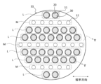
- FIG. FIG. 2 is a cross-sectional view taken along the line II--II in FIG.
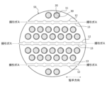
- FIG. 3 is a sectional view taken along line III--III in FIG.
- FIG. 4 is a sectional view along IV-IV in FIG.
- FIG. 2 to 4 show cross sections along the short direction perpendicular to the longitudinal direction of the reactor 1.
- FIG. A cross section in the following description means a cross section along the lateral direction.
- the longitudinal direction is an example of the "first direction” according to the invention
- the lateral direction is an example of the "second direction” according to the invention.
- the reactor 1 is a so-called membrane reactor used for the conversion reaction from raw material gas to liquid fuel.
- the source gas contains at least hydrogen and carbon oxide. At least one of carbon monoxide and carbon dioxide can be used as the carbon oxide.
- the source gas may be a so-called synthesis gas (Syngas).
- the liquid fuel is a fuel that is liquid at room temperature and pressure, or a fuel that can be liquefied at room temperature and pressure. Examples of fuels in a liquid state at normal temperature and pressure include methanol, ethanol, liquid fuels represented by C n H 2 (m-2n) (m is an integer less than 90, n is an integer less than 30), and these mixtures. Fuels that can be liquefied at room temperature and under pressure include, for example, propane, butane, and mixtures thereof.
- reaction formula (1) for synthesizing methanol by catalytically hydrogenating a raw material gas containing hydrogen and carbon dioxide in the presence of a catalyst is as follows. CO2 + 3H2 ⁇ CH3OH + H2O (1)
- the above reaction is an equilibrium reaction, and is preferably carried out at high temperature and high pressure (eg, 180°C or higher, 2 MPa or higher) in order to increase both conversion efficiency and reaction rate.
- the liquid fuel is in a gaseous state when it is synthesized and remains in a gaseous state at least until it flows out of the reactor 1 .
- the reactor 1 preferably has heat resistance and pressure resistance suitable for the desired conditions for synthesizing the liquid fuel.
- the reactor 1 is formed in a monolithic shape.
- a monolith means a shape having a plurality of holes penetrating in the longitudinal direction, and is a concept including a honeycomb.
- the reactor 1 has a first end face S1, a second end face S2 and a side face S3.
- the first end surface S1 is provided on the opposite side of the second end surface S2.
- the side surface S3 continues to the outer edges of the first end surface S1 and the second end surface S2.
- the reactor 1 is formed in a cylindrical shape.
- the reactor 1 includes a porous support 10, a separation membrane 20, a catalyst 30, a first sealing portion 40 and a second sealing portion 50.
- the porous support 10 is a columnar body extending in the longitudinal direction of the reactor 1 .
- the cross-sectional shape of the porous support 10 is circular.
- a circle is a concept that includes not only a perfect circle but also a circle with a degree of distortion that is unavoidable in manufacturing.
- the porous support 10 is composed of a porous material.
- a ceramic material a metal material, a resin material, or the like can be used, and a ceramic material is particularly suitable.
- aggregates for ceramic materials include alumina (Al 2 O 3 ), titania (TiO 2 ), mullite (Al 2 O 3 SiO 2 ), cerven and cordierite (Mg 2 Al 4 Si 5 O 18 ). At least one of them can be used. At least one of titania, mullite, sinterable alumina, silica, glass frit, clay mineral, and sinterable cordierite can be used as the inorganic binder for the ceramic material. However, the ceramic material does not have to contain an inorganic binder.
- the porous support 10 has multiple first cells 11, multiple second cells 12, multiple first slits 13, and multiple second slits .
- the first cell 11 extends in the longitudinal direction of the reactor 1.
- the first cells 11 longitudinally penetrate the porous support 10 .
- the first cell 11 opens to each of the first end face S1 and the second end face S2 of the reactor 1 .
- a raw material gas is caused to flow through the first cell 11 .
- the cross-sectional shape of the first cell 11 is circular. As a result, the occurrence of cracks in the separation membrane 20 can be suppressed.
- the second cell 12 extends in the longitudinal direction of the reactor 1.
- a second cell 12 is formed inside the porous support 10 .
- the second cells 12 do not longitudinally penetrate the porous support 10 .
- the second cell 12 does not open to the first end face S1 and the second end face S2 of the reactor 1 respectively.
- both ends of the second cell 12 are sealed with first and second plugging portions 17 and 18 (see FIG. 5).
- the first and second plugging portions 17 and 18 can be made of the porous material described above.
- a sweep gas for sweeping the water vapor permeating through the separation membrane 20 is supplied to the second cell 12 .
- An inert gas for example, nitrogen
- air can be used as the sweep gas.
- the cross-sectional shape of the second cell 12 is circular.
- the first cells 11 are arranged in six rows L along the width direction, and the second cells 12 are arranged in three rows M along the width direction. ing.
- Each column L includes two or more first cells 11 .
- Each column M includes five or more second cells 12 .
- a row L of the first cells 11 is provided on each side of the row M of the second cells 12 .
- the number of columns L, the number of columns M, and their arrangement can be changed as appropriate.
- the number of the first cells 11 included in the column L and the number of the second cells 12 included in the column M can be changed as appropriate.
- the first slit 13 is formed at one end of the reactor 1. As shown in FIG. 3, the first slit 13 extends in the lateral direction. The first slit 13 penetrates the porous support 10 and one end of the row M of the second cells 12 . Both ends of the first slit 13 open to the side surface S3 of the reactor 1 . A sweep gas flows through the first slit 13 . In this embodiment, the sweep gas is supplied from both ends of the first slit 13 .
- the second slit 14 is formed at the other end of the reactor 1, as shown in FIG. As shown in FIG. 4, the second slit 14 extends in the lateral direction. The second slit 14 penetrates the porous support 10 and the other end of the row M of the second cells 12 . Both ends of the second slit 14 open to the side surface S3 of the reactor 1 . A sweep gas flows through the second slit 14 . In this embodiment, the sweep gas is discharged from both ends of the second slit 14 .
- the second cells 12 are arranged in three rows M, three first and second slits 13 and 14 are provided, respectively.
- the number of slits 13 and 14 can be appropriately changed according to the number of columns M of the second cells 12 .
- the porous support 10 is formed by firing the molded body in which the first and second cells 11 and 12 are formed, and then punching the first and second slits 13 and 14 for each row M of the second slits 14. produced.
- the average cross-sectional area of the multiple first cells 11 is larger than the average cross-sectional area of the multiple second cells 12 .
- the volume of the space (the non-permeate side space inside the separation membrane 20) in which the catalyst 30 described later is arranged can be increased. . Therefore, since the amount of the catalyst 30 that promotes the conversion reaction can be increased, the conversion efficiency from the raw material gas to the liquid fuel can be improved.
- the average cross-sectional area of the second cells 12 relatively small, it is possible to prevent the occupancy rate of the porous support 10 in the cross section from being lowered. Therefore, since the volume of voids in the porous support 10 can be reduced, the strength of the porous support 10 can be ensured. Therefore, according to the reactor 1 according to the present embodiment, it is possible to achieve both improvement in conversion efficiency and ensuring strength.
- the average cross-sectional area of the first cells 11 is obtained by arithmetically averaging the cross-sectional areas of the first cells 11.
- the average cross-sectional area of the second cells 12 is obtained by arithmetically averaging the cross-sectional areas of each second cell 12 .
- the cross-sectional shape of the first cell 11 is circular
- the cross-sectional shape of the second cell 12 is circular. Therefore, by making the average diameter of the second cells 12 smaller than the average diameter of the first cells 11 , the average cross-sectional area of the second cells 12 can be made smaller than the average cross-sectional area of the first cells 11 . Also, the average cross-sectional area of each of the first and second cells 11 and 12 can be easily adjusted by changing the average diameter of the first and second cells 11 and 12 .
- the average diameter of the first cells 11 is obtained by arithmetically averaging the equivalent circle diameters of the first cells 11 in the cross section.
- the average diameter of the second cells 12 is obtained by arithmetically averaging the equivalent circle diameters of the second cells 12 in the cross section.
- the equivalent circle diameter is the diameter of a circle having the same area as the cross section of the cell. When the cell cross section is a perfect circle, the equivalent circle diameter is the same as the diameter of the perfect circle.
- the total area ratio of the first cells 11 in the cross section is not particularly limited, it can be, for example, 15% or more and 40% or less. In this case, the number of first cells 11 can be, for example, 20 or more and 1700 or less.
- the total area ratio of the second cells 12 in the cross section is not particularly limited, it can be, for example, 5% or more and 15% or less. In this case, the number of second cells 12 can be, for example, 40 or more and 700 or less.
- the total area fraction of the first cells 11 is obtained by dividing the total cross-sectional area of the first cells 11 by the total cross-sectional area of the porous support 10 (including the cross-sectional areas of the first and second cells 11, 12).
- the total area fraction of the second cells 12 is obtained by dividing the total cross-sectional area of the second cells 12 by the total area of the porous support 10 in the cross-section.
- the average cross-sectional areas, average diameters, and total area ratios of the first and second cells 11 and 12 are calculated in the central cross section of the porous support 10 in the longitudinal direction.
- Separation membrane 20 is supported by porous support 10 . Separation membrane 20 is formed on the inner peripheral surface of first cell 11 . Separation membrane 20 is cylindrical. Separation membrane 20 surrounds catalyst 30 .
- the separation membrane 20 allows water vapor, which is one of the products of the conversion reaction from the source gas to the liquid fuel, to permeate.
- the equilibrium shift effect can be used to shift the reaction equilibrium of the above formula (1) to the product side.
- the separation membrane 20 preferably has a water vapor permeability coefficient of 100 nmol/(s ⁇ Pa ⁇ m 2 ) or more.
- the water vapor permeability coefficient can be determined by a known method (see Ind. Eng. Chem. Res., 40, 163-175 (2001)).
- the separation membrane 20 preferably has a separation factor of 100 or more.
- the separation factor can be determined by a known method (see Fig. 1 of "Separation and Purification Technology 239 (2020) 116533").
- An inorganic membrane can be used as the separation membrane 20 .
- An inorganic film is preferable because it has heat resistance, pressure resistance, and water vapor resistance.
- inorganic membranes include zeolite membranes, silica membranes, alumina membranes, and composite membranes thereof.
- an LTA-type zeolite membrane in which the molar ratio (Si/Al) of silicon element (Si) and aluminum element (Al) is 1.0 or more and 3.0 or less is preferable because it has excellent water vapor permeability. be.
- the catalyst 30 promotes the conversion reaction shown in formula (1) above.
- the catalyst 30 is arranged in the non-permeate side space inside the separation membrane 20 .
- the catalyst 30 is preferably filled in the non-permeate side space, but may be arranged in layers or islands on the inner peripheral surface of the separation membrane 20 .
- a known catalyst suitable for the conversion reaction to the desired liquid fuel can be used.
- the catalyst 30 include metal catalysts (copper, palladium, etc.), oxide catalysts (zinc oxide, zirconia, gallium oxide, etc.), and composite catalysts thereof (copper-zinc oxide, copper-zinc oxide-alumina , copper-zinc oxide-chromium oxide-alumina, copper-cobalt-titania, and catalysts obtained by modifying these with palladium).
- the first seal portion 40 covers one end face of the porous support 10, as shown in FIG.
- the first seal portion 40 prevents the raw material gas from entering the porous support 10 .
- the first seal portion 40 is formed so as not to block the opening of the first cell 11 .
- the first seal portion 40 can be made of glass, metal, rubber, resin, or the like.
- the second seal portion 50 covers the other end surface of the porous support 10, as shown in FIG.
- the second seal portion 50 prevents liquid fuel from entering the porous support 10 .
- the second seal portion 50 is formed so as not to block the opening of the first cell 11 .
- the second seal portion 50 can be made of glass, metal, rubber, resin, or the like.
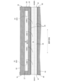
- FIG. 5 is a cross-sectional view taken along line VV of FIG.
- the liquid fuel synthesizing method using the reactor 1 includes a step of flowing the sweep gas through the second flow path 12 while flowing the raw material gas through the first cell 11 .
- the raw material gas flows into the first cell 11 from the inlet e1 of the first cell 11 .
- the action of the catalyst 30 synthesizes a liquid fuel from the raw material gas and produces steam.
- the synthesized liquid fuel flows out from the outlet e2 of the first cell 11 to the outside.
- Water vapor which is one of the products, sequentially permeates the separation membrane 20 and the porous support 10 and moves to the second channel 12 .
- the sweep gas flows into the first slit 13 from the inlet d1 of the first slit 13 and then into the second cell 12 .
- the sweep gas that has flowed into the second cell 12 takes in the water vapor that has permeated through the separation membrane 20 and absorbs reaction heat associated with the conversion reaction, and then flows out from the outlet d2 of the second slit 14 to the outside.
- the direction of the source gas flowing through the first cell 11 is the same as the direction of the sweep gas flowing through the second cell 12, but it may be opposite.
- the cross-sectional shape of the first cell 11 is circular in the above embodiment, it may be elliptical. Even if the cross-sectional shape of the first cell 11 is elliptical, the occurrence of cracks in the separation membrane 20 can be suppressed.
- the elliptical shape also includes those having a degree of distortion that is unavoidable in manufacturing. Even when the cross-sectional shape of the first cells 11 is elliptical, the average diameter of the first cells 11 can be obtained by arithmetically averaging the equivalent circle diameters of the first cells 11, as described in the above embodiment. .
- the cross-sectional shape of the second cell 12 is circular in the above embodiment, it may be oval, polygonal, or any other complicated shape.
- the elliptical shape and polygonal shape include those having a degree of distortion that is unavoidable in manufacturing. Polygons include not only polygons in which all angles are curved, but also polygons in which at least one corner is curved. Even if the cross section of the second cells 12 is elliptical, polygonal, or the like, the average diameter of the second cells 12 can be obtained by arithmetically averaging the circle-equivalent diameters of the second cells 12 as described in the above embodiment. obtained by
- only one column M may be provided, or two or more columns may be provided.
- the position of the row M is not particularly limited, and may be provided at a position shifted from the center point of the porous support 10 .
- at least two rows M may be orthogonal or cross each other.
- the strength of the porous support 10 can be improved compared to the case where all the rows M are arranged orthogonally or without crossing each other.
- the first cells 11 may be arranged in a region where the column M is not provided regardless of whether the column L is formed.
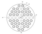
- a plurality of second cells 12 can be arranged point-symmetrically with respect to the center point CP of the porous support 10 .
- Point symmetry means that when the cross section of the second cell 12 is rotated 180 degrees about the center point CP, it not only coincides with the original cross section, but also the original cross section due to deviations and distortions that inevitably occur in manufacturing. It is a concept that includes the case where it does not partially match the cross section of .
- the second cells 12 are arranged in two columns M, two each of the first and second slits 13 and 14 penetrating the columns M are provided.
- the two first slits 13 intersect (join) each other near the center point CP, and the two second slits 14 intersect each other near the center point CP.
- the number of columns M of the second cells 12 is not limited, and may be one or more columns.
- the separation membrane 20 is configured to permeate water vapor, which is one of the products of the conversion reaction from the raw material gas to the liquid fuel, but is not limited to this.
- the separation membrane 20 may permeate the liquid fuel itself produced by the conversion reaction from the source gas to the liquid fuel. Also in this case, the reaction equilibrium of the above formula (1) can be shifted to the product side.
- the separation membrane 20 is permeable to the liquid fuel, even when the liquid fuel is generated by a reaction that does not generate water vapor (eg, H 2 +CO ⁇ CH 3 OH), the reaction equilibrium is shifted to the product side. be able to.
- a reaction that does not generate water vapor eg, H 2 +CO ⁇ CH 3 OH
- the shape of the reactor is not limited to a monolithic type, and may be a tubular type.
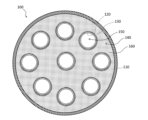
- FIG. 7 is a cross-sectional view along the longitudinal direction of the tubular reactor 100 according to this modified example.
- FIG. 8 is a cross-sectional view along the lateral direction of a tubular reactor 100 according to this modification.
- the longitudinal direction is an example of the "first direction” according to the invention, and the lateral direction is an example of the "second direction” according to the invention.
- the transverse direction is perpendicular to the longitudinal direction.
- the reactor 100 is used for a conversion reaction from a source gas containing at least hydrogen and carbon oxide to a liquid fuel.
- the reactor 100 includes a housing 110, a plurality of porous supports 120, a plurality of separation membranes 130, a first cell 140, a plurality of second cells 150, and a catalyst 160.
- the housing 110 is a housing for the reactor 100.
- the housing 110 is formed in a tubular shape extending along the longitudinal direction.
- the porous support 120 supports the separation membrane 130.
- the porous support 120 is formed in a cylindrical shape extending along the longitudinal direction.
- the outer surface of porous support 120 is surrounded by separation membrane 130 .
- the inside of the porous support 120 is hollow.
- the constituent material of the porous support 120 is the same as that of the porous support 10 according to the above embodiment.
- the separation membrane 130 is supported by the porous support 120. In this modification, separation membrane 130 is placed on the outer surface of porous support 120 . Separation membrane 130 is formed in a tubular shape extending along the longitudinal direction. Separation membrane 130 is surrounded by catalyst 160 . The separation membrane 130 allows a product (steam or liquid fuel) generated from the raw material gas in the first cell 140 to permeate toward each second cell 150 . The characteristics and constituent materials of the separation membrane 130 are the same as those of the separation membrane 20 according to the above embodiment. Separation membrane 130 may be arranged on the inner surface of porous support 120 .
- the first cell 140 is provided on the non-permeation side of each separation membrane 130 .
- a first cell 140 is the space between the outer surface of each separation membrane 130 and the inner surface of the housing 110 .
- a raw material gas flows through the first cell 140 .
- the first cell 140 extends longitudinally.
- the second cell 150 is provided inside the porous support 120 .
- a second cell 150 is a space on the permeation side of each separation membrane 130 .
- a sweep gas is flowed through the second cell 150 .
- the second cells 150 extend longitudinally.
- the catalyst 160 is placed inside the first cell 140 .
- the catalyst 160 accelerates the conversion reaction from raw material gas to liquid fuel.
- the constituent material of the catalyst 160 is the same as that of the catalyst 30 according to the above embodiment.
- the value obtained by dividing the cross-sectional area of the first cells 140 by the number of the second cells 150 is larger than the average cross-sectional area of the second cells 150 in the cross section along the width direction.
- the volume of the first cell 140 allocated to one second cell 150 can be increased. That is, when the first cell 140 is regarded as an assembly of a plurality of small cells corresponding to a plurality of second cells 150, the volume of each small cell can be made larger than the volume of each second cell 150.
- the number of second cells 150 can be increased while increasing the value obtained by dividing the cross-sectional area of the first cells 140 by the number of second cells 150 over the average cross-sectional area of the second cells 150. Less stress is placed on each second cell 150 due to the weight and thermal expansion of the catalyst 160 . Therefore, damage to the porous support 120 of each second cell 150 can be suppressed.
Landscapes
- Chemical & Material Sciences (AREA)
- Organic Chemistry (AREA)
- Chemical Kinetics & Catalysis (AREA)
- Engineering & Computer Science (AREA)
- Water Supply & Treatment (AREA)
- Materials Engineering (AREA)
- Physics & Mathematics (AREA)
- Fluid Mechanics (AREA)
- Separation Using Semi-Permeable Membranes (AREA)
- Physical Or Chemical Processes And Apparatus (AREA)
- Catalysts (AREA)
Priority Applications (5)
| Application Number | Priority Date | Filing Date | Title |
|---|---|---|---|
| JP2024501396A JP7641438B2 (ja) | 2022-02-21 | 2023-02-15 | リアクタ |
| AU2023220484A AU2023220484B2 (en) | 2022-02-21 | 2023-02-15 | Reactor |
| CN202380022389.7A CN118742374A (zh) | 2022-02-21 | 2023-02-15 | 反应器 |
| EP23756386.1A EP4483992A4 (en) | 2022-02-21 | 2023-02-15 | REACTOR |
| US18/743,252 US20240326008A1 (en) | 2022-02-21 | 2024-06-14 | Reactor |
Applications Claiming Priority (2)
| Application Number | Priority Date | Filing Date | Title |
|---|---|---|---|
| JP2022025130 | 2022-02-21 | ||
| JP2022-025130 | 2022-02-21 |
Related Child Applications (1)
| Application Number | Title | Priority Date | Filing Date |
|---|---|---|---|
| US18/743,252 Continuation US20240326008A1 (en) | 2022-02-21 | 2024-06-14 | Reactor |
Publications (1)
| Publication Number | Publication Date |
|---|---|
| WO2023157861A1 true WO2023157861A1 (ja) | 2023-08-24 |
Family
ID=87578339
Family Applications (1)
| Application Number | Title | Priority Date | Filing Date |
|---|---|---|---|
| PCT/JP2023/005154 Ceased WO2023157861A1 (ja) | 2022-02-21 | 2023-02-15 | リアクタ |
Country Status (6)
| Country | Link |
|---|---|
| US (1) | US20240326008A1 (https=) |
| EP (1) | EP4483992A4 (https=) |
| JP (1) | JP7641438B2 (https=) |
| CN (1) | CN118742374A (https=) |
| AU (1) | AU2023220484B2 (https=) |
| WO (1) | WO2023157861A1 (https=) |
Citations (8)
| Publication number | Priority date | Publication date | Assignee | Title |
|---|---|---|---|---|
| JPH0840703A (ja) * | 1994-05-23 | 1996-02-13 | Ngk Insulators Ltd | 水素製造装置 |
| JP2004075440A (ja) * | 2002-08-14 | 2004-03-11 | Ishikawajima Harima Heavy Ind Co Ltd | 水素製造装置 |
| JP2010528124A (ja) * | 2007-05-18 | 2010-08-19 | エクソンモービル リサーチ アンド エンジニアリング カンパニー | 重質炭化水素とメタンとを含む混合ガスからの重質炭化水素の除去 |
| JP2013111529A (ja) * | 2011-11-29 | 2013-06-10 | Kyocera Corp | 分離膜付き多孔質体 |
| JP2018008940A (ja) | 2016-07-04 | 2018-01-18 | 公益財団法人地球環境産業技術研究機構 | メタノール製造方法およびメタノール製造装置 |
| JP2020132439A (ja) * | 2019-02-13 | 2020-08-31 | Jfeスチール株式会社 | 水素ガスの製造方法および製造設備列 |
| WO2022260063A1 (ja) * | 2021-06-08 | 2022-12-15 | 日本碍子株式会社 | メンブレンリアクタ |
| JP7245585B1 (ja) * | 2021-12-22 | 2023-03-24 | 日本碍子株式会社 | リアクタ及び液体燃料合成方法 |
Family Cites Families (4)
| Publication number | Priority date | Publication date | Assignee | Title |
|---|---|---|---|---|
| JP2004306020A (ja) * | 2003-03-24 | 2004-11-04 | Ngk Insulators Ltd | セラミックフィルタ |
| JP2008513337A (ja) * | 2004-09-21 | 2008-05-01 | ウスター ポリテクニック インスティチュート | 膜増強反応器 |
| US7169213B2 (en) * | 2004-10-29 | 2007-01-30 | Corning Incorporated | Multi-channel cross-flow porous device |
| JP2017149616A (ja) * | 2016-02-25 | 2017-08-31 | 日本碍子株式会社 | 水素回収メンブレンリアクター、水素回収システム及び水素回収方法 |
-
2023
- 2023-02-15 WO PCT/JP2023/005154 patent/WO2023157861A1/ja not_active Ceased
- 2023-02-15 AU AU2023220484A patent/AU2023220484B2/en active Active
- 2023-02-15 JP JP2024501396A patent/JP7641438B2/ja active Active
- 2023-02-15 CN CN202380022389.7A patent/CN118742374A/zh active Pending
- 2023-02-15 EP EP23756386.1A patent/EP4483992A4/en active Pending
-
2024
- 2024-06-14 US US18/743,252 patent/US20240326008A1/en active Pending
Patent Citations (8)
| Publication number | Priority date | Publication date | Assignee | Title |
|---|---|---|---|---|
| JPH0840703A (ja) * | 1994-05-23 | 1996-02-13 | Ngk Insulators Ltd | 水素製造装置 |
| JP2004075440A (ja) * | 2002-08-14 | 2004-03-11 | Ishikawajima Harima Heavy Ind Co Ltd | 水素製造装置 |
| JP2010528124A (ja) * | 2007-05-18 | 2010-08-19 | エクソンモービル リサーチ アンド エンジニアリング カンパニー | 重質炭化水素とメタンとを含む混合ガスからの重質炭化水素の除去 |
| JP2013111529A (ja) * | 2011-11-29 | 2013-06-10 | Kyocera Corp | 分離膜付き多孔質体 |
| JP2018008940A (ja) | 2016-07-04 | 2018-01-18 | 公益財団法人地球環境産業技術研究機構 | メタノール製造方法およびメタノール製造装置 |
| JP2020132439A (ja) * | 2019-02-13 | 2020-08-31 | Jfeスチール株式会社 | 水素ガスの製造方法および製造設備列 |
| WO2022260063A1 (ja) * | 2021-06-08 | 2022-12-15 | 日本碍子株式会社 | メンブレンリアクタ |
| JP7245585B1 (ja) * | 2021-12-22 | 2023-03-24 | 日本碍子株式会社 | リアクタ及び液体燃料合成方法 |
Non-Patent Citations (2)
| Title |
|---|
| IND. ENG. CHEM. RES., vol. 40, 2001, pages 163 - 175 |
| See also references of EP4483992A4 |
Also Published As
| Publication number | Publication date |
|---|---|
| AU2023220484B2 (en) | 2025-10-23 |
| JP7641438B2 (ja) | 2025-03-06 |
| CN118742374A (zh) | 2024-10-01 |
| JPWO2023157861A1 (https=) | 2023-08-24 |
| EP4483992A4 (en) | 2025-10-22 |
| EP4483992A1 (en) | 2025-01-01 |
| US20240326008A1 (en) | 2024-10-03 |
| AU2023220484A1 (en) | 2024-07-18 |
Similar Documents
| Publication | Publication Date | Title |
|---|---|---|
| JP7500781B2 (ja) | メンブレンリアクタ | |
| WO2023157861A1 (ja) | リアクタ | |
| JP7245585B1 (ja) | リアクタ及び液体燃料合成方法 | |
| US20240017236A1 (en) | Reactor module, liquid fuel synthesis method, separation membrane module, and separation method | |
| JP2025508208A (ja) | 分離膜モジュール | |
| JP7612879B2 (ja) | リアクタ及び液体燃料合成方法 | |
| JP7797193B2 (ja) | リアクタ及び液体燃料合成方法 | |
| JP7853755B2 (ja) | 分離膜モジュール | |
| US20250161884A1 (en) | Separation membrane module | |
| WO2023210802A1 (en) | Membrane assembly and separation membrane module | |
| JP7650376B2 (ja) | 分離膜モジュール | |
| JP7419610B2 (ja) | リアクタモジュール、液体燃料合成方法、分離膜モジュール及び分離方法 | |
| JP7853401B2 (ja) | リアクタモジュール及び分離膜モジュール | |
| JP2025508209A (ja) | 膜アセンブリ及び分離膜モジュール |
Legal Events
| Date | Code | Title | Description |
|---|---|---|---|
| 121 | Ep: the epo has been informed by wipo that ep was designated in this application |
Ref document number: 23756386 Country of ref document: EP Kind code of ref document: A1 |
|
| WWE | Wipo information: entry into national phase |
Ref document number: AU2023220484 Country of ref document: AU |
|
| WWE | Wipo information: entry into national phase |
Ref document number: 2024501396 Country of ref document: JP |
|
| ENP | Entry into the national phase |
Ref document number: 2023220484 Country of ref document: AU Date of ref document: 20230215 Kind code of ref document: A |
|
| WWE | Wipo information: entry into national phase |
Ref document number: 202380022389.7 Country of ref document: CN |
|
| WWE | Wipo information: entry into national phase |
Ref document number: 2023756386 Country of ref document: EP |
|
| NENP | Non-entry into the national phase |
Ref country code: DE |
|
| ENP | Entry into the national phase |
Ref document number: 2023756386 Country of ref document: EP Effective date: 20240923 |