WO2023157861A1 - Reactor - Google Patents
Reactor Download PDFInfo
- Publication number
- WO2023157861A1 WO2023157861A1 PCT/JP2023/005154 JP2023005154W WO2023157861A1 WO 2023157861 A1 WO2023157861 A1 WO 2023157861A1 JP 2023005154 W JP2023005154 W JP 2023005154W WO 2023157861 A1 WO2023157861 A1 WO 2023157861A1
- Authority
- WO
- WIPO (PCT)
- Prior art keywords
- cells
- cross
- cell
- reactor
- porous support
- Prior art date
Links
- 239000012528 membrane Substances 0.000 claims abstract description 68
- 238000000926 separation method Methods 0.000 claims abstract description 64
- 239000003054 catalyst Substances 0.000 claims abstract description 39
- 239000007789 gas Substances 0.000 claims description 52
- 239000000446 fuel Substances 0.000 claims description 34
- 239000007788 liquid Substances 0.000 claims description 32
- 239000002994 raw material Substances 0.000 claims description 18
- CURLTUGMZLYLDI-UHFFFAOYSA-N Carbon dioxide Chemical compound O=C=O CURLTUGMZLYLDI-UHFFFAOYSA-N 0.000 claims description 15
- 239000012466 permeate Substances 0.000 claims description 15
- 239000000047 product Substances 0.000 claims description 11
- 229910002090 carbon oxide Inorganic materials 0.000 claims description 9
- 239000001257 hydrogen Substances 0.000 claims description 9
- 229910052739 hydrogen Inorganic materials 0.000 claims description 9
- UFHFLCQGNIYNRP-UHFFFAOYSA-N Hydrogen Chemical compound [H][H] UFHFLCQGNIYNRP-UHFFFAOYSA-N 0.000 claims description 8
- 230000002093 peripheral effect Effects 0.000 claims description 5
- 230000000149 penetrating effect Effects 0.000 claims description 4
- 230000001737 promoting effect Effects 0.000 claims 1
- 238000006243 chemical reaction Methods 0.000 description 22
- 238000012986 modification Methods 0.000 description 13
- 230000004048 modification Effects 0.000 description 13
- XLYOFNOQVPJJNP-UHFFFAOYSA-N water Chemical compound O XLYOFNOQVPJJNP-UHFFFAOYSA-N 0.000 description 13
- OKKJLVBELUTLKV-UHFFFAOYSA-N Methanol Chemical compound OC OKKJLVBELUTLKV-UHFFFAOYSA-N 0.000 description 10
- 238000012935 Averaging Methods 0.000 description 6
- GWEVSGVZZGPLCZ-UHFFFAOYSA-N Titan oxide Chemical compound O=[Ti]=O GWEVSGVZZGPLCZ-UHFFFAOYSA-N 0.000 description 5
- PNEYBMLMFCGWSK-UHFFFAOYSA-N aluminium oxide Inorganic materials [O-2].[O-2].[O-2].[Al+3].[Al+3] PNEYBMLMFCGWSK-UHFFFAOYSA-N 0.000 description 5
- 229910010293 ceramic material Inorganic materials 0.000 description 5
- 238000000034 method Methods 0.000 description 5
- 230000002194 synthesizing effect Effects 0.000 description 5
- LFQSCWFLJHTTHZ-UHFFFAOYSA-N Ethanol Chemical compound CCO LFQSCWFLJHTTHZ-UHFFFAOYSA-N 0.000 description 4
- KDLHZDBZIXYQEI-UHFFFAOYSA-N Palladium Chemical compound [Pd] KDLHZDBZIXYQEI-UHFFFAOYSA-N 0.000 description 4
- VYPSYNLAJGMNEJ-UHFFFAOYSA-N Silicium dioxide Chemical compound O=[Si]=O VYPSYNLAJGMNEJ-UHFFFAOYSA-N 0.000 description 4
- 239000013256 coordination polymer Substances 0.000 description 4
- 238000004519 manufacturing process Methods 0.000 description 4
- 239000000463 material Substances 0.000 description 4
- 229910002092 carbon dioxide Inorganic materials 0.000 description 3
- 239000000470 constituent Substances 0.000 description 3
- 239000011521 glass Substances 0.000 description 3
- 229910052751 metal Inorganic materials 0.000 description 3
- 239000002184 metal Substances 0.000 description 3
- 230000035699 permeability Effects 0.000 description 3
- 239000011148 porous material Substances 0.000 description 3
- 239000011347 resin Substances 0.000 description 3
- 229920005989 resin Polymers 0.000 description 3
- 229910018072 Al 2 O 3 Inorganic materials 0.000 description 2
- IJGRMHOSHXDMSA-UHFFFAOYSA-N Atomic nitrogen Chemical compound N#N IJGRMHOSHXDMSA-UHFFFAOYSA-N 0.000 description 2
- ATUOYWHBWRKTHZ-UHFFFAOYSA-N Propane Chemical compound CCC ATUOYWHBWRKTHZ-UHFFFAOYSA-N 0.000 description 2
- 229910021536 Zeolite Inorganic materials 0.000 description 2
- XLOMVQKBTHCTTD-UHFFFAOYSA-N Zinc monoxide Chemical compound [Zn]=O XLOMVQKBTHCTTD-UHFFFAOYSA-N 0.000 description 2
- MCMNRKCIXSYSNV-UHFFFAOYSA-N Zirconium dioxide Chemical compound O=[Zr]=O MCMNRKCIXSYSNV-UHFFFAOYSA-N 0.000 description 2
- 239000011230 binding agent Substances 0.000 description 2
- 239000001569 carbon dioxide Substances 0.000 description 2
- 239000002131 composite material Substances 0.000 description 2
- 229910052878 cordierite Inorganic materials 0.000 description 2
- JSKIRARMQDRGJZ-UHFFFAOYSA-N dimagnesium dioxido-bis[(1-oxido-3-oxo-2,4,6,8,9-pentaoxa-1,3-disila-5,7-dialuminabicyclo[3.3.1]nonan-7-yl)oxy]silane Chemical compound [Mg++].[Mg++].[O-][Si]([O-])(O[Al]1O[Al]2O[Si](=O)O[Si]([O-])(O1)O2)O[Al]1O[Al]2O[Si](=O)O[Si]([O-])(O1)O2 JSKIRARMQDRGJZ-UHFFFAOYSA-N 0.000 description 2
- HNPSIPDUKPIQMN-UHFFFAOYSA-N dioxosilane;oxo(oxoalumanyloxy)alumane Chemical compound O=[Si]=O.O=[Al]O[Al]=O HNPSIPDUKPIQMN-UHFFFAOYSA-N 0.000 description 2
- KZHJGOXRZJKJNY-UHFFFAOYSA-N dioxosilane;oxo(oxoalumanyloxy)alumane Chemical compound O=[Si]=O.O=[Si]=O.O=[Al]O[Al]=O.O=[Al]O[Al]=O.O=[Al]O[Al]=O KZHJGOXRZJKJNY-UHFFFAOYSA-N 0.000 description 2
- 239000000203 mixture Substances 0.000 description 2
- 229910052863 mullite Inorganic materials 0.000 description 2
- 238000012856 packing Methods 0.000 description 2
- 229910052763 palladium Inorganic materials 0.000 description 2
- 239000005060 rubber Substances 0.000 description 2
- 238000007789 sealing Methods 0.000 description 2
- 239000000377 silicon dioxide Substances 0.000 description 2
- 238000010408 sweeping Methods 0.000 description 2
- 239000010457 zeolite Substances 0.000 description 2
- UGFAIRIUMAVXCW-UHFFFAOYSA-N Carbon monoxide Chemical compound [O+]#[C-] UGFAIRIUMAVXCW-UHFFFAOYSA-N 0.000 description 1
- RYGMFSIKBFXOCR-UHFFFAOYSA-N Copper Chemical compound [Cu] RYGMFSIKBFXOCR-UHFFFAOYSA-N 0.000 description 1
- 229910004298 SiO 2 Inorganic materials 0.000 description 1
- XUIMIQQOPSSXEZ-UHFFFAOYSA-N Silicon Chemical compound [Si] XUIMIQQOPSSXEZ-UHFFFAOYSA-N 0.000 description 1
- 229910010413 TiO 2 Inorganic materials 0.000 description 1
- XAGFODPZIPBFFR-UHFFFAOYSA-N aluminium Chemical compound [Al] XAGFODPZIPBFFR-UHFFFAOYSA-N 0.000 description 1
- 238000013459 approach Methods 0.000 description 1
- 230000015572 biosynthetic process Effects 0.000 description 1
- 239000001273 butane Substances 0.000 description 1
- 229910002091 carbon monoxide Inorganic materials 0.000 description 1
- 239000002734 clay mineral Substances 0.000 description 1
- 229910052802 copper Inorganic materials 0.000 description 1
- 239000010949 copper Substances 0.000 description 1
- TVZPLCNGKSPOJA-UHFFFAOYSA-N copper zinc Chemical compound [Cu].[Zn] TVZPLCNGKSPOJA-UHFFFAOYSA-N 0.000 description 1
- YXSIKEMDQWEQTO-UHFFFAOYSA-N copper zinc chromium(3+) oxygen(2-) Chemical compound [O-2].[Zn+2].[Cr+3].[Cu+2] YXSIKEMDQWEQTO-UHFFFAOYSA-N 0.000 description 1
- VODBHXZOIQDDST-UHFFFAOYSA-N copper zinc oxygen(2-) Chemical compound [O--].[O--].[Cu++].[Zn++] VODBHXZOIQDDST-UHFFFAOYSA-N 0.000 description 1
- AJNVQOSZGJRYEI-UHFFFAOYSA-N digallium;oxygen(2-) Chemical compound [O-2].[O-2].[O-2].[Ga+3].[Ga+3] AJNVQOSZGJRYEI-UHFFFAOYSA-N 0.000 description 1
- 230000000694 effects Effects 0.000 description 1
- 238000005516 engineering process Methods 0.000 description 1
- 238000010304 firing Methods 0.000 description 1
- 229910001195 gallium oxide Inorganic materials 0.000 description 1
- 150000002431 hydrogen Chemical class 0.000 description 1
- 239000011261 inert gas Substances 0.000 description 1
- 239000007769 metal material Substances 0.000 description 1
- VNWKTOKETHGBQD-UHFFFAOYSA-N methane Natural products C VNWKTOKETHGBQD-UHFFFAOYSA-N 0.000 description 1
- IJDNQMDRQITEOD-UHFFFAOYSA-N n-butane Chemical compound CCCC IJDNQMDRQITEOD-UHFFFAOYSA-N 0.000 description 1
- OFBQJSOFQDEBGM-UHFFFAOYSA-N n-pentane Natural products CCCCC OFBQJSOFQDEBGM-UHFFFAOYSA-N 0.000 description 1
- 229910052757 nitrogen Inorganic materials 0.000 description 1
- 239000001294 propane Substances 0.000 description 1
- 238000004080 punching Methods 0.000 description 1
- 238000000746 purification Methods 0.000 description 1
- 229910052710 silicon Inorganic materials 0.000 description 1
- 239000010703 silicon Substances 0.000 description 1
- 238000003786 synthesis reaction Methods 0.000 description 1
- 239000011787 zinc oxide Substances 0.000 description 1
Images


Classifications
-
- B—PERFORMING OPERATIONS; TRANSPORTING
- B01—PHYSICAL OR CHEMICAL PROCESSES OR APPARATUS IN GENERAL
- B01D—SEPARATION
- B01D61/00—Processes of separation using semi-permeable membranes, e.g. dialysis, osmosis or ultrafiltration; Apparatus, accessories or auxiliary operations specially adapted therefor
- B01D61/36—Pervaporation; Membrane distillation; Liquid permeation
-
- B01J35/56—
-
- C—CHEMISTRY; METALLURGY
- C07—ORGANIC CHEMISTRY
- C07B—GENERAL METHODS OF ORGANIC CHEMISTRY; APPARATUS THEREFOR
- C07B61/00—Other general methods
-
- C—CHEMISTRY; METALLURGY
- C07—ORGANIC CHEMISTRY
- C07C—ACYCLIC OR CARBOCYCLIC COMPOUNDS
- C07C29/00—Preparation of compounds having hydroxy or O-metal groups bound to a carbon atom not belonging to a six-membered aromatic ring
- C07C29/15—Preparation of compounds having hydroxy or O-metal groups bound to a carbon atom not belonging to a six-membered aromatic ring by reduction of oxides of carbon exclusively
- C07C29/151—Preparation of compounds having hydroxy or O-metal groups bound to a carbon atom not belonging to a six-membered aromatic ring by reduction of oxides of carbon exclusively with hydrogen or hydrogen-containing gases
- C07C29/152—Preparation of compounds having hydroxy or O-metal groups bound to a carbon atom not belonging to a six-membered aromatic ring by reduction of oxides of carbon exclusively with hydrogen or hydrogen-containing gases characterised by the reactor used
-
- C—CHEMISTRY; METALLURGY
- C07—ORGANIC CHEMISTRY
- C07C—ACYCLIC OR CARBOCYCLIC COMPOUNDS
- C07C31/00—Saturated compounds having hydroxy or O-metal groups bound to acyclic carbon atoms
- C07C31/02—Monohydroxylic acyclic alcohols
- C07C31/04—Methanol
-
- C—CHEMISTRY; METALLURGY
- C07—ORGANIC CHEMISTRY
- C07C—ACYCLIC OR CARBOCYCLIC COMPOUNDS
- C07C31/00—Saturated compounds having hydroxy or O-metal groups bound to acyclic carbon atoms
- C07C31/02—Monohydroxylic acyclic alcohols
- C07C31/08—Ethanol
Definitions
- the present invention relates to reactors.
- Patent Literature 1 discloses a tubular reactor comprising a first cell provided on the non-permeate side of a plurality of separation membranes and a second cell provided on the permeate side of each separation membrane. Each separation membrane is supported by a cylindrical porous support.
- the first cell is filled with a catalyst and supplied with a raw material gas.
- a sweep gas is supplied to the second channel for sweeping the product that has permeated the separation membrane.
- the monolithic reactor includes a porous support, a plurality of first cells penetrating through the porous support and through which a source gas flows, a plurality of second cells formed in the porous support through which a sweep gas flows, It comprises a separation membrane formed on the inner peripheral surface of each first cell, and a catalyst arranged inside the separation membrane.
- the amount of catalyst can be increased by reducing the number of separation membranes, and the conversion efficiency can be improved. Therefore, the porous support supporting the separation membrane is easily damaged. Therefore, even in a tubular reactor, it is not easy to achieve both improvement in conversion efficiency and securing of strength.
- An object of the present invention is to provide a reactor capable of improving conversion efficiency and ensuring strength.
- the reactor according to the first aspect of the present invention is a monolithic reactor used for the conversion reaction of a raw material gas containing at least hydrogen and carbon oxide into a liquid fuel.
- the reactor includes a porous support, a plurality of first cells through which source gas flows, a plurality of second cells through which sweep gas flows, a separation membrane, and a catalyst.
- the plurality of first cells penetrate the porous support in a first direction.
- the plurality of second cells extend in a first direction within the porous support.
- the separation membrane is formed on the inner peripheral surface of each of the plurality of first cells and allows the products of the conversion reaction to permeate therethrough.
- the catalyst is placed inside the separation membrane to promote the conversion reaction. In a cross section along a second direction perpendicular to the first direction, the average cross-sectional area of the plurality of first cells is larger than the average cross-sectional area of the plurality of second cells.
- a reactor according to a second aspect of the present invention relates to the first aspect, wherein in the cross section, each of the plurality of first cells is circular, and in the cross section, each of the plurality of second cells is circular, In the cross section, the average diameter of the plurality of first cells is larger than the average diameter of the plurality of second cells.
- a reactor according to a third aspect of the present invention relates to the first aspect, wherein in the cross section, each of the plurality of first cells is circular, and in the cross section, each of the plurality of second cells is polygonal. , in the cross-section, the average diameter of the plurality of first cells is greater than the average diameter of the plurality of second cells.
- a reactor according to a fourth aspect of the present invention relates to any one of the first to third aspects, and includes a plurality of first slits through which the sweep gas flows and a plurality of second slits through which the sweep gas flows.
- the plurality of second cells are arranged in a plurality of columns.
- Each of the plurality of first slits penetrates through one end of each of the plurality of rows, and each of the plurality of second slits penetrates through the other end of each of the plurality of rows.
- the reactor according to the fifth aspect of the present invention is a tubular reactor used for the conversion reaction of raw material gas containing at least hydrogen and carbon oxide into liquid fuel.
- the reactor includes multiple separation membranes, first cells, multiple second cells, and a catalyst.
- Each of the plurality of separation membranes is supported by a porous support.
- the first cell is provided on a non-permeation side of each of the plurality of separation membranes, through which the source gas flows.
- the plurality of second cells are provided on the permeation side of each of the plurality of separation membranes, through which the sweep gas flows.
- the catalyst is disposed on the non-permeate side of each of the plurality of separation membranes to facilitate the conversion reaction.
- Each of the first cell and the plurality of second cells extends in a first direction. In a cross section along a second direction perpendicular to the first direction, the value obtained by dividing the cross-sectional area of the first cells by the number of the second cells is larger than the average cross-sectional area of
- FIG. 1 is a perspective view of a monolithic reactor 1 according to an embodiment; FIG. II-II sectional view of Fig. 1 III-III sectional view of Fig. 1 IV-IV sectional view of Fig. 1 VV sectional view of Fig. 2 Cross-sectional view of a porous support according to modification 3 Sectional view of a tubular reactor 100 according to Modification 6 Sectional view of a tubular reactor 100 according to Modification 6
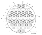
- FIG. 1 is a perspective view of the reactor 1.
- FIG. FIG. 2 is a cross-sectional view taken along the line II--II in FIG.
- FIG. 3 is a sectional view taken along line III--III in FIG.
- FIG. 4 is a sectional view along IV-IV in FIG.
- FIG. 2 to 4 show cross sections along the short direction perpendicular to the longitudinal direction of the reactor 1.
- FIG. A cross section in the following description means a cross section along the lateral direction.
- the longitudinal direction is an example of the "first direction” according to the invention
- the lateral direction is an example of the "second direction” according to the invention.
- the reactor 1 is a so-called membrane reactor used for the conversion reaction from raw material gas to liquid fuel.
- the source gas contains at least hydrogen and carbon oxide. At least one of carbon monoxide and carbon dioxide can be used as the carbon oxide.
- the source gas may be a so-called synthesis gas (Syngas).
- the liquid fuel is a fuel that is liquid at room temperature and pressure, or a fuel that can be liquefied at room temperature and pressure. Examples of fuels in a liquid state at normal temperature and pressure include methanol, ethanol, liquid fuels represented by C n H 2 (m-2n) (m is an integer less than 90, n is an integer less than 30), and these mixtures. Fuels that can be liquefied at room temperature and under pressure include, for example, propane, butane, and mixtures thereof.
- reaction formula (1) for synthesizing methanol by catalytically hydrogenating a raw material gas containing hydrogen and carbon dioxide in the presence of a catalyst is as follows. CO2 + 3H2 ⁇ CH3OH + H2O (1)
- the above reaction is an equilibrium reaction, and is preferably carried out at high temperature and high pressure (eg, 180°C or higher, 2 MPa or higher) in order to increase both conversion efficiency and reaction rate.
- the liquid fuel is in a gaseous state when it is synthesized and remains in a gaseous state at least until it flows out of the reactor 1 .
- the reactor 1 preferably has heat resistance and pressure resistance suitable for the desired conditions for synthesizing the liquid fuel.
- the reactor 1 is formed in a monolithic shape.
- a monolith means a shape having a plurality of holes penetrating in the longitudinal direction, and is a concept including a honeycomb.
- the reactor 1 has a first end face S1, a second end face S2 and a side face S3.
- the first end surface S1 is provided on the opposite side of the second end surface S2.
- the side surface S3 continues to the outer edges of the first end surface S1 and the second end surface S2.
- the reactor 1 is formed in a cylindrical shape.
- the reactor 1 includes a porous support 10, a separation membrane 20, a catalyst 30, a first sealing portion 40 and a second sealing portion 50.
- the porous support 10 is a columnar body extending in the longitudinal direction of the reactor 1 .
- the cross-sectional shape of the porous support 10 is circular.
- a circle is a concept that includes not only a perfect circle but also a circle with a degree of distortion that is unavoidable in manufacturing.
- the porous support 10 is composed of a porous material.
- a ceramic material a metal material, a resin material, or the like can be used, and a ceramic material is particularly suitable.
- aggregates for ceramic materials include alumina (Al 2 O 3 ), titania (TiO 2 ), mullite (Al 2 O 3 SiO 2 ), cerven and cordierite (Mg 2 Al 4 Si 5 O 18 ). At least one of them can be used. At least one of titania, mullite, sinterable alumina, silica, glass frit, clay mineral, and sinterable cordierite can be used as the inorganic binder for the ceramic material. However, the ceramic material does not have to contain an inorganic binder.
- the porous support 10 has multiple first cells 11, multiple second cells 12, multiple first slits 13, and multiple second slits .
- the first cell 11 extends in the longitudinal direction of the reactor 1.
- the first cells 11 longitudinally penetrate the porous support 10 .
- the first cell 11 opens to each of the first end face S1 and the second end face S2 of the reactor 1 .
- a raw material gas is caused to flow through the first cell 11 .
- the cross-sectional shape of the first cell 11 is circular. As a result, the occurrence of cracks in the separation membrane 20 can be suppressed.
- the second cell 12 extends in the longitudinal direction of the reactor 1.
- a second cell 12 is formed inside the porous support 10 .
- the second cells 12 do not longitudinally penetrate the porous support 10 .
- the second cell 12 does not open to the first end face S1 and the second end face S2 of the reactor 1 respectively.
- both ends of the second cell 12 are sealed with first and second plugging portions 17 and 18 (see FIG. 5).
- the first and second plugging portions 17 and 18 can be made of the porous material described above.
- a sweep gas for sweeping the water vapor permeating through the separation membrane 20 is supplied to the second cell 12 .
- An inert gas for example, nitrogen
- air can be used as the sweep gas.
- the cross-sectional shape of the second cell 12 is circular.
- the first cells 11 are arranged in six rows L along the width direction, and the second cells 12 are arranged in three rows M along the width direction. ing.
- Each column L includes two or more first cells 11 .
- Each column M includes five or more second cells 12 .
- a row L of the first cells 11 is provided on each side of the row M of the second cells 12 .
- the number of columns L, the number of columns M, and their arrangement can be changed as appropriate.
- the number of the first cells 11 included in the column L and the number of the second cells 12 included in the column M can be changed as appropriate.
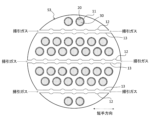
- the first slit 13 is formed at one end of the reactor 1. As shown in FIG. 3, the first slit 13 extends in the lateral direction. The first slit 13 penetrates the porous support 10 and one end of the row M of the second cells 12 . Both ends of the first slit 13 open to the side surface S3 of the reactor 1 . A sweep gas flows through the first slit 13 . In this embodiment, the sweep gas is supplied from both ends of the first slit 13 .
- the second slit 14 is formed at the other end of the reactor 1, as shown in FIG. As shown in FIG. 4, the second slit 14 extends in the lateral direction. The second slit 14 penetrates the porous support 10 and the other end of the row M of the second cells 12 . Both ends of the second slit 14 open to the side surface S3 of the reactor 1 . A sweep gas flows through the second slit 14 . In this embodiment, the sweep gas is discharged from both ends of the second slit 14 .
- the second cells 12 are arranged in three rows M, three first and second slits 13 and 14 are provided, respectively.
- the number of slits 13 and 14 can be appropriately changed according to the number of columns M of the second cells 12 .
- the porous support 10 is formed by firing the molded body in which the first and second cells 11 and 12 are formed, and then punching the first and second slits 13 and 14 for each row M of the second slits 14. produced.
- the average cross-sectional area of the multiple first cells 11 is larger than the average cross-sectional area of the multiple second cells 12 .
- the volume of the space (the non-permeate side space inside the separation membrane 20) in which the catalyst 30 described later is arranged can be increased. . Therefore, since the amount of the catalyst 30 that promotes the conversion reaction can be increased, the conversion efficiency from the raw material gas to the liquid fuel can be improved.
- the average cross-sectional area of the second cells 12 relatively small, it is possible to prevent the occupancy rate of the porous support 10 in the cross section from being lowered. Therefore, since the volume of voids in the porous support 10 can be reduced, the strength of the porous support 10 can be ensured. Therefore, according to the reactor 1 according to the present embodiment, it is possible to achieve both improvement in conversion efficiency and ensuring strength.
- the average cross-sectional area of the first cells 11 is obtained by arithmetically averaging the cross-sectional areas of the first cells 11.
- the average cross-sectional area of the second cells 12 is obtained by arithmetically averaging the cross-sectional areas of each second cell 12 .
- the cross-sectional shape of the first cell 11 is circular
- the cross-sectional shape of the second cell 12 is circular. Therefore, by making the average diameter of the second cells 12 smaller than the average diameter of the first cells 11 , the average cross-sectional area of the second cells 12 can be made smaller than the average cross-sectional area of the first cells 11 . Also, the average cross-sectional area of each of the first and second cells 11 and 12 can be easily adjusted by changing the average diameter of the first and second cells 11 and 12 .
- the average diameter of the first cells 11 is obtained by arithmetically averaging the equivalent circle diameters of the first cells 11 in the cross section.
- the average diameter of the second cells 12 is obtained by arithmetically averaging the equivalent circle diameters of the second cells 12 in the cross section.
- the equivalent circle diameter is the diameter of a circle having the same area as the cross section of the cell. When the cell cross section is a perfect circle, the equivalent circle diameter is the same as the diameter of the perfect circle.
- the total area ratio of the first cells 11 in the cross section is not particularly limited, it can be, for example, 15% or more and 40% or less. In this case, the number of first cells 11 can be, for example, 20 or more and 1700 or less.
- the total area ratio of the second cells 12 in the cross section is not particularly limited, it can be, for example, 5% or more and 15% or less. In this case, the number of second cells 12 can be, for example, 40 or more and 700 or less.
- the total area fraction of the first cells 11 is obtained by dividing the total cross-sectional area of the first cells 11 by the total cross-sectional area of the porous support 10 (including the cross-sectional areas of the first and second cells 11, 12).
- the total area fraction of the second cells 12 is obtained by dividing the total cross-sectional area of the second cells 12 by the total area of the porous support 10 in the cross-section.
- the average cross-sectional areas, average diameters, and total area ratios of the first and second cells 11 and 12 are calculated in the central cross section of the porous support 10 in the longitudinal direction.
- Separation membrane 20 is supported by porous support 10 . Separation membrane 20 is formed on the inner peripheral surface of first cell 11 . Separation membrane 20 is cylindrical. Separation membrane 20 surrounds catalyst 30 .
- the separation membrane 20 allows water vapor, which is one of the products of the conversion reaction from the source gas to the liquid fuel, to permeate.
- the equilibrium shift effect can be used to shift the reaction equilibrium of the above formula (1) to the product side.
- the separation membrane 20 preferably has a water vapor permeability coefficient of 100 nmol/(s ⁇ Pa ⁇ m 2 ) or more.
- the water vapor permeability coefficient can be determined by a known method (see Ind. Eng. Chem. Res., 40, 163-175 (2001)).
- the separation membrane 20 preferably has a separation factor of 100 or more.
- the separation factor can be determined by a known method (see Fig. 1 of "Separation and Purification Technology 239 (2020) 116533").
- An inorganic membrane can be used as the separation membrane 20 .
- An inorganic film is preferable because it has heat resistance, pressure resistance, and water vapor resistance.
- inorganic membranes include zeolite membranes, silica membranes, alumina membranes, and composite membranes thereof.
- an LTA-type zeolite membrane in which the molar ratio (Si/Al) of silicon element (Si) and aluminum element (Al) is 1.0 or more and 3.0 or less is preferable because it has excellent water vapor permeability. be.
- the catalyst 30 promotes the conversion reaction shown in formula (1) above.
- the catalyst 30 is arranged in the non-permeate side space inside the separation membrane 20 .
- the catalyst 30 is preferably filled in the non-permeate side space, but may be arranged in layers or islands on the inner peripheral surface of the separation membrane 20 .
- a known catalyst suitable for the conversion reaction to the desired liquid fuel can be used.
- the catalyst 30 include metal catalysts (copper, palladium, etc.), oxide catalysts (zinc oxide, zirconia, gallium oxide, etc.), and composite catalysts thereof (copper-zinc oxide, copper-zinc oxide-alumina , copper-zinc oxide-chromium oxide-alumina, copper-cobalt-titania, and catalysts obtained by modifying these with palladium).
- the first seal portion 40 covers one end face of the porous support 10, as shown in FIG.
- the first seal portion 40 prevents the raw material gas from entering the porous support 10 .
- the first seal portion 40 is formed so as not to block the opening of the first cell 11 .
- the first seal portion 40 can be made of glass, metal, rubber, resin, or the like.
- the second seal portion 50 covers the other end surface of the porous support 10, as shown in FIG.
- the second seal portion 50 prevents liquid fuel from entering the porous support 10 .
- the second seal portion 50 is formed so as not to block the opening of the first cell 11 .
- the second seal portion 50 can be made of glass, metal, rubber, resin, or the like.
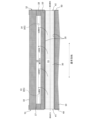
- FIG. 5 is a cross-sectional view taken along line VV of FIG.
- the liquid fuel synthesizing method using the reactor 1 includes a step of flowing the sweep gas through the second flow path 12 while flowing the raw material gas through the first cell 11 .
- the raw material gas flows into the first cell 11 from the inlet e1 of the first cell 11 .
- the action of the catalyst 30 synthesizes a liquid fuel from the raw material gas and produces steam.
- the synthesized liquid fuel flows out from the outlet e2 of the first cell 11 to the outside.
- Water vapor which is one of the products, sequentially permeates the separation membrane 20 and the porous support 10 and moves to the second channel 12 .
- the sweep gas flows into the first slit 13 from the inlet d1 of the first slit 13 and then into the second cell 12 .
- the sweep gas that has flowed into the second cell 12 takes in the water vapor that has permeated through the separation membrane 20 and absorbs reaction heat associated with the conversion reaction, and then flows out from the outlet d2 of the second slit 14 to the outside.
- the direction of the source gas flowing through the first cell 11 is the same as the direction of the sweep gas flowing through the second cell 12, but it may be opposite.
- the cross-sectional shape of the first cell 11 is circular in the above embodiment, it may be elliptical. Even if the cross-sectional shape of the first cell 11 is elliptical, the occurrence of cracks in the separation membrane 20 can be suppressed.
- the elliptical shape also includes those having a degree of distortion that is unavoidable in manufacturing. Even when the cross-sectional shape of the first cells 11 is elliptical, the average diameter of the first cells 11 can be obtained by arithmetically averaging the equivalent circle diameters of the first cells 11, as described in the above embodiment. .
- the cross-sectional shape of the second cell 12 is circular in the above embodiment, it may be oval, polygonal, or any other complicated shape.
- the elliptical shape and polygonal shape include those having a degree of distortion that is unavoidable in manufacturing. Polygons include not only polygons in which all angles are curved, but also polygons in which at least one corner is curved. Even if the cross section of the second cells 12 is elliptical, polygonal, or the like, the average diameter of the second cells 12 can be obtained by arithmetically averaging the circle-equivalent diameters of the second cells 12 as described in the above embodiment. obtained by
- only one column M may be provided, or two or more columns may be provided.
- the position of the row M is not particularly limited, and may be provided at a position shifted from the center point of the porous support 10 .
- at least two rows M may be orthogonal or cross each other.
- the strength of the porous support 10 can be improved compared to the case where all the rows M are arranged orthogonally or without crossing each other.
- the first cells 11 may be arranged in a region where the column M is not provided regardless of whether the column L is formed.
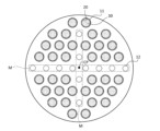
- a plurality of second cells 12 can be arranged point-symmetrically with respect to the center point CP of the porous support 10 .
- Point symmetry means that when the cross section of the second cell 12 is rotated 180 degrees about the center point CP, it not only coincides with the original cross section, but also the original cross section due to deviations and distortions that inevitably occur in manufacturing. It is a concept that includes the case where it does not partially match the cross section of .
- the second cells 12 are arranged in two columns M, two each of the first and second slits 13 and 14 penetrating the columns M are provided.
- the two first slits 13 intersect (join) each other near the center point CP, and the two second slits 14 intersect each other near the center point CP.
- the number of columns M of the second cells 12 is not limited, and may be one or more columns.
- the separation membrane 20 is configured to permeate water vapor, which is one of the products of the conversion reaction from the raw material gas to the liquid fuel, but is not limited to this.
- the separation membrane 20 may permeate the liquid fuel itself produced by the conversion reaction from the source gas to the liquid fuel. Also in this case, the reaction equilibrium of the above formula (1) can be shifted to the product side.
- the separation membrane 20 is permeable to the liquid fuel, even when the liquid fuel is generated by a reaction that does not generate water vapor (eg, H 2 +CO ⁇ CH 3 OH), the reaction equilibrium is shifted to the product side. be able to.
- a reaction that does not generate water vapor eg, H 2 +CO ⁇ CH 3 OH
- the shape of the reactor is not limited to a monolithic type, and may be a tubular type.
- FIG. 7 is a cross-sectional view along the longitudinal direction of the tubular reactor 100 according to this modified example.
- FIG. 8 is a cross-sectional view along the lateral direction of a tubular reactor 100 according to this modification.
- the longitudinal direction is an example of the "first direction” according to the invention, and the lateral direction is an example of the "second direction” according to the invention.
- the transverse direction is perpendicular to the longitudinal direction.
- the reactor 100 is used for a conversion reaction from a source gas containing at least hydrogen and carbon oxide to a liquid fuel.
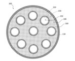
- the reactor 100 includes a housing 110, a plurality of porous supports 120, a plurality of separation membranes 130, a first cell 140, a plurality of second cells 150, and a catalyst 160.
- the housing 110 is a housing for the reactor 100.
- the housing 110 is formed in a tubular shape extending along the longitudinal direction.
- the porous support 120 supports the separation membrane 130.
- the porous support 120 is formed in a cylindrical shape extending along the longitudinal direction.
- the outer surface of porous support 120 is surrounded by separation membrane 130 .
- the inside of the porous support 120 is hollow.
- the constituent material of the porous support 120 is the same as that of the porous support 10 according to the above embodiment.
- the separation membrane 130 is supported by the porous support 120. In this modification, separation membrane 130 is placed on the outer surface of porous support 120 . Separation membrane 130 is formed in a tubular shape extending along the longitudinal direction. Separation membrane 130 is surrounded by catalyst 160 . The separation membrane 130 allows a product (steam or liquid fuel) generated from the raw material gas in the first cell 140 to permeate toward each second cell 150 . The characteristics and constituent materials of the separation membrane 130 are the same as those of the separation membrane 20 according to the above embodiment. Separation membrane 130 may be arranged on the inner surface of porous support 120 .
- the first cell 140 is provided on the non-permeation side of each separation membrane 130 .
- a first cell 140 is the space between the outer surface of each separation membrane 130 and the inner surface of the housing 110 .
- a raw material gas flows through the first cell 140 .
- the first cell 140 extends longitudinally.
- the second cell 150 is provided inside the porous support 120 .
- a second cell 150 is a space on the permeation side of each separation membrane 130 .
- a sweep gas is flowed through the second cell 150 .
- the second cells 150 extend longitudinally.
- the catalyst 160 is placed inside the first cell 140 .
- the catalyst 160 accelerates the conversion reaction from raw material gas to liquid fuel.
- the constituent material of the catalyst 160 is the same as that of the catalyst 30 according to the above embodiment.
- the value obtained by dividing the cross-sectional area of the first cells 140 by the number of the second cells 150 is larger than the average cross-sectional area of the second cells 150 in the cross section along the width direction.
- the volume of the first cell 140 allocated to one second cell 150 can be increased. That is, when the first cell 140 is regarded as an assembly of a plurality of small cells corresponding to a plurality of second cells 150, the volume of each small cell can be made larger than the volume of each second cell 150.
- the number of second cells 150 can be increased while increasing the value obtained by dividing the cross-sectional area of the first cells 140 by the number of second cells 150 over the average cross-sectional area of the second cells 150. Less stress is placed on each second cell 150 due to the weight and thermal expansion of the catalyst 160 . Therefore, damage to the porous support 120 of each second cell 150 can be suppressed.
Abstract
A reactor (1) is equipped with a porous support body (10), a plurality of first cells (11) through which a source gas flows, a plurality of second cells (12) through which a sweep gas flows, a separation membrane (20), and a catalyst (30). The first cell (11) penetrates the porous support body (10) in the longitudinal direction. The second cell (12) extends in the porous support body (10) in the longitudinal direction. The separation membrane (20) is formed on the inner periphery surface of the first cell (11). The catalyst (30) is disposed inside the separation membrane (10). In a cross-section taken along the transverse direction, the average cross-sectional area of the first cell (11) is larger than the average cross-sectional area of the second cell (12).
Description
本発明は、リアクタに関する。
The present invention relates to reactors.
近年、水素及び酸化炭素を含有する原料ガスからメタノールやエタノールなどの液体燃料(具体的には、常温常圧下で液体状態の燃料)への転化反応における生成物を分離することによって転化効率を向上させることのできるリアクタが開発されている。
In recent years, the conversion efficiency has been improved by separating the products in the conversion reaction from the raw material gas containing hydrogen and carbon oxide to liquid fuels such as methanol and ethanol (specifically, fuels that are in a liquid state at normal temperature and pressure). Reactors have been developed that can
例えば、特許文献1には、複数の分離膜の非透過側に設けられる第1セルと、各分離膜の透過側に設けられる第2セルとを備えるチューブ型のリアクタが開示されている。各分離膜は、筒状の多孔質支持体によって支持される。第1セルには、触媒が充填されており、原料ガスが供給される。第2流路には、分離膜を透過した生成物を掃引するための掃引ガスが供給される。
For example, Patent Literature 1 discloses a tubular reactor comprising a first cell provided on the non-permeate side of a plurality of separation membranes and a second cell provided on the permeate side of each separation membrane. Each separation membrane is supported by a cylindrical porous support. The first cell is filled with a catalyst and supplied with a raw material gas. A sweep gas is supplied to the second channel for sweeping the product that has permeated the separation membrane.
本発明者らは、上述した転化反応をモノリス型のリアクタで行うことを検討した。モノリス型のリアクタは、多孔質支持体と、多孔質支持体を貫通し、原料ガスが流れる複数の第1セルと、多孔質支持体内に形成され、掃引ガスが流れる複数の第2セルと、各第1セルの内周面に形成される分離膜と、分離膜の内側に配置される触媒とを備える。
The inventors considered carrying out the conversion reaction described above in a monolithic reactor. The monolithic reactor includes a porous support, a plurality of first cells penetrating through the porous support and through which a source gas flows, a plurality of second cells formed in the porous support through which a sweep gas flows, It comprises a separation membrane formed on the inner peripheral surface of each first cell, and a catalyst arranged inside the separation membrane.
モノリス型のリアクタでは、第1セルの直径を大きくすると触媒の充填率を最密充填に近づけることができるため、触媒量を多くすることができ転化効率が向上する一方、多孔質支持体の強度は低くなってしまう。そのため、モノリス型のリアクタにおいて、転化効率の向上と強度の確保とを両立させることは容易ではない。
In a monolithic reactor, increasing the diameter of the first cell allows the packing ratio of the catalyst to approach the closest packing. becomes low. Therefore, in a monolithic reactor, it is not easy to achieve both improvement in conversion efficiency and securing of strength.
また、チューブ型のリアクタでは、分離膜の本数を減らすことによって触媒量を多くすることができ転化効率を向上できる一方、増量した触媒の重量だけでなく触媒の熱膨張に起因する応力も分離膜にかかるため、分離膜を支持する多孔質支持体が破損しやすい。そのため、チューブ型のリアクタにおいても、転化効率の向上と強度の確保とを両立させることは容易ではない。
In a tubular reactor, the amount of catalyst can be increased by reducing the number of separation membranes, and the conversion efficiency can be improved. Therefore, the porous support supporting the separation membrane is easily damaged. Therefore, even in a tubular reactor, it is not easy to achieve both improvement in conversion efficiency and securing of strength.
本発明は、転化効率の向上と強度の確保とを両立可能なリアクタを提供することを目的とする。
An object of the present invention is to provide a reactor capable of improving conversion efficiency and ensuring strength.
本発明の第1側面に係るリアクタは、少なくとも水素及び酸化炭素を含有する原料ガスから液体燃料への転化反応に用いられるモノリス型のリアクタである。リアクタは、多孔質支持体と、原料ガスが流れる複数の第1セルと、掃引ガスが流れる複数の第2セルと、分離膜と、触媒とを備える。前記複数の第1セルは、前記多孔質支持体を第1方向に貫通する。前記複数の第2セルは、前記多孔質支持体内を第1方向に延びる。前記分離膜は、前記複数の第1セルそれぞれの内周面に形成され、転化反応の生成物を透過させる。前記触媒は、前記分離膜の内側に配置され、転化反応を促進させる。前記第1方向に垂直な第2方向に沿った断面において、前記複数の第1セルの平均断面積は、前記複数の第2セルの平均断面積より大きい。
The reactor according to the first aspect of the present invention is a monolithic reactor used for the conversion reaction of a raw material gas containing at least hydrogen and carbon oxide into a liquid fuel. The reactor includes a porous support, a plurality of first cells through which source gas flows, a plurality of second cells through which sweep gas flows, a separation membrane, and a catalyst. The plurality of first cells penetrate the porous support in a first direction. The plurality of second cells extend in a first direction within the porous support. The separation membrane is formed on the inner peripheral surface of each of the plurality of first cells and allows the products of the conversion reaction to permeate therethrough. The catalyst is placed inside the separation membrane to promote the conversion reaction. In a cross section along a second direction perpendicular to the first direction, the average cross-sectional area of the plurality of first cells is larger than the average cross-sectional area of the plurality of second cells.
本発明の第2側面に係るリアクタは、上記第1側面に係り、前記断面において、前記複数の第1セルそれぞれは円形であり、前記断面において、前記複数の第2セルそれぞれは円形であり、前記断面において、前記複数の第1セルの平均直径は、前記複数の第2セルの平均直径より大きい。
A reactor according to a second aspect of the present invention relates to the first aspect, wherein in the cross section, each of the plurality of first cells is circular, and in the cross section, each of the plurality of second cells is circular, In the cross section, the average diameter of the plurality of first cells is larger than the average diameter of the plurality of second cells.
本発明の第3側面に係るリアクタは、上記第1側面に係り、前記断面において、前記複数の第1セルそれぞれは円形であり、前記断面において、前記複数の第2セルそれぞれは多角形であり、前記断面において、前記複数の第1セルの平均直径は、前記複数の第2セルの平均直径より大きい。
A reactor according to a third aspect of the present invention relates to the first aspect, wherein in the cross section, each of the plurality of first cells is circular, and in the cross section, each of the plurality of second cells is polygonal. , in the cross-section, the average diameter of the plurality of first cells is greater than the average diameter of the plurality of second cells.
本発明の第4側面に係るリアクタは、上記第1乃至第3いずれかの側面に係り、前記掃引ガスが流れる複数の第1スリットと、前記掃引ガスが流れる複数の第2スリットとを備える。前記断面において、前記複数の第2セルは、複数の列に配列されている。前記複数の第1スリットそれぞれは、前記複数の列それぞれの一端部を貫通し、前記複数の第2スリットそれぞれは、前記複数の列それぞれの他端部を貫通する。
A reactor according to a fourth aspect of the present invention relates to any one of the first to third aspects, and includes a plurality of first slits through which the sweep gas flows and a plurality of second slits through which the sweep gas flows. In the cross section, the plurality of second cells are arranged in a plurality of columns. Each of the plurality of first slits penetrates through one end of each of the plurality of rows, and each of the plurality of second slits penetrates through the other end of each of the plurality of rows.
本発明の第5側面に係るリアクタは、少なくとも水素及び酸化炭素を含有する原料ガスから液体燃料への転化反応に用いられるチューブ型のリアクタである。リアクタは、複数の分離膜と、第1セルと、複数の第2セルと、触媒とを備える。前記複数の分離膜それぞれは、多孔質支持体によって支持される。前記第1セルは、前記複数の分離膜それぞれの非透過側に設けられ、前記原料ガスが流れる。前記複数の第2セルは、前記複数の分離膜それぞれの透過側に設けられ、掃引ガスが流れる。前記触媒は、前記複数の分離膜それぞれの前記非透過側に配置され、前記転化反応を促進させる。前記第1セル及び前記複数の第2セルそれぞれは、第1方向に延びている。前記第1方向に垂直な第2方向に沿った断面において、前記第1セルの断面積を前記第2セルの本数で割った値は、前記複数の第2セルの平均断面積より大きい。
The reactor according to the fifth aspect of the present invention is a tubular reactor used for the conversion reaction of raw material gas containing at least hydrogen and carbon oxide into liquid fuel. The reactor includes multiple separation membranes, first cells, multiple second cells, and a catalyst. Each of the plurality of separation membranes is supported by a porous support. The first cell is provided on a non-permeation side of each of the plurality of separation membranes, through which the source gas flows. The plurality of second cells are provided on the permeation side of each of the plurality of separation membranes, through which the sweep gas flows. The catalyst is disposed on the non-permeate side of each of the plurality of separation membranes to facilitate the conversion reaction. Each of the first cell and the plurality of second cells extends in a first direction. In a cross section along a second direction perpendicular to the first direction, the value obtained by dividing the cross-sectional area of the first cells by the number of the second cells is larger than the average cross-sectional area of the plurality of second cells.
本発明によれば、転化効率の向上と強度の確保とを両立可能なリアクタを提供することができる。
According to the present invention, it is possible to provide a reactor capable of improving conversion efficiency and ensuring strength.
次に、図面を参照しながら、本発明の実施形態について説明する。ただし、図面は模式的なものであり、各寸法の比率等は現実のものとは異なっている場合がある。
Next, an embodiment of the present invention will be described with reference to the drawings. However, the drawings are schematic, and the ratio of each dimension may differ from the actual one.
(リアクタ1)
図1は、リアクタ1の斜視図である。図2は、図1のII-II断面図である。図3は、図1のIII-III断面図である。図4は、図1のIV-IV断面図である。 (Reactor 1)
FIG. 1 is a perspective view of thereactor 1. FIG. FIG. 2 is a cross-sectional view taken along the line II--II in FIG. FIG. 3 is a sectional view taken along line III--III in FIG. FIG. 4 is a sectional view along IV-IV in FIG.
図1は、リアクタ1の斜視図である。図2は、図1のII-II断面図である。図3は、図1のIII-III断面図である。図4は、図1のIV-IV断面図である。 (Reactor 1)
FIG. 1 is a perspective view of the
図2~図4には、リアクタ1の長手方向に垂直な短手方向に沿った断面が図示されている。以下の説明において断面という場合、短手方向に沿った断面を意味する。長手方向は本発明に係る「第1方向」の一例であり、短手方向は本発明に係る「第2方向」の一例である。
2 to 4 show cross sections along the short direction perpendicular to the longitudinal direction of the reactor 1. FIG. A cross section in the following description means a cross section along the lateral direction. The longitudinal direction is an example of the "first direction" according to the invention, and the lateral direction is an example of the "second direction" according to the invention.
リアクタ1は、原料ガスから液体燃料への転化反応に用いられる所謂メンブレンリアクタである。原料ガスは、少なくとも水素及び酸化炭素を含有する。酸化炭素としては、一酸化炭素及び二酸化炭素の少なくとも一方を用いることができる。原料ガスは、いわゆる合成ガス(Syngas)であってもよい。液体燃料は、常温常圧で液体状態の燃料、又は、常温加圧状態で液化可能な燃料である。常温常圧で液体状態の燃料としては、例えばメタノール、エタノール、CnH2(m-2n)(mは90未満の整数、nは30未満の整数)で表される液体燃料、及びこれらの混合物が挙げられる。常温加圧状態で液化可能な燃料としては、例えばプロパン、ブタン、及びこれらの混合物などが挙げられる。
The reactor 1 is a so-called membrane reactor used for the conversion reaction from raw material gas to liquid fuel. The source gas contains at least hydrogen and carbon oxide. At least one of carbon monoxide and carbon dioxide can be used as the carbon oxide. The source gas may be a so-called synthesis gas (Syngas). The liquid fuel is a fuel that is liquid at room temperature and pressure, or a fuel that can be liquefied at room temperature and pressure. Examples of fuels in a liquid state at normal temperature and pressure include methanol, ethanol, liquid fuels represented by C n H 2 (m-2n) (m is an integer less than 90, n is an integer less than 30), and these mixtures. Fuels that can be liquefied at room temperature and under pressure include, for example, propane, butane, and mixtures thereof.
例えば、水素及び二酸化炭素を含有する原料ガスを触媒存在下で接触水素化することでメタノールを合成する際の反応式(1)は次の通りである。
CO2+3H2 ⇔ CH3OH+H2O (1) For example, reaction formula (1) for synthesizing methanol by catalytically hydrogenating a raw material gas containing hydrogen and carbon dioxide in the presence of a catalyst is as follows.
CO2 + 3H2 ⇔ CH3OH + H2O (1)
CO2+3H2 ⇔ CH3OH+H2O (1) For example, reaction formula (1) for synthesizing methanol by catalytically hydrogenating a raw material gas containing hydrogen and carbon dioxide in the presence of a catalyst is as follows.
CO2 + 3H2 ⇔ CH3OH + H2O (1)
上記反応は平衡反応であり、転化効率及び反応速度の両方を高めるには高温高圧下(例えば、180℃以上、2MPa以上)で実施されることが好ましい。液体燃料は、合成された時点では気体状態であり、少なくともリアクタ1から流出するまでは気体状態のまま維持される。リアクタ1は、所望の液体燃料の合成条件に適した耐熱性及び耐圧性を有することが好ましい。
The above reaction is an equilibrium reaction, and is preferably carried out at high temperature and high pressure (eg, 180°C or higher, 2 MPa or higher) in order to increase both conversion efficiency and reaction rate. The liquid fuel is in a gaseous state when it is synthesized and remains in a gaseous state at least until it flows out of the reactor 1 . The reactor 1 preferably has heat resistance and pressure resistance suitable for the desired conditions for synthesizing the liquid fuel.
図1に示すように、リアクタ1は、モノリス型に形成される。モノリスとは、長手方向に貫通した複数の孔を有する形状を意味し、ハニカムを含む概念である。
As shown in FIG. 1, the reactor 1 is formed in a monolithic shape. A monolith means a shape having a plurality of holes penetrating in the longitudinal direction, and is a concept including a honeycomb.
リアクタ1は、第1端面S1、第2端面S2及び側面S3を有する。第1端面S1は、第2端面S2の反対側に設けられる。側面S3は、第1端面S1及び第2端面S2の外縁に連なる。本実施形態において、リアクタ1は円柱状に形成されている。
The reactor 1 has a first end face S1, a second end face S2 and a side face S3. The first end surface S1 is provided on the opposite side of the second end surface S2. The side surface S3 continues to the outer edges of the first end surface S1 and the second end surface S2. In this embodiment, the reactor 1 is formed in a cylindrical shape.
図1~図4に示すように、リアクタ1は、多孔質支持体10、分離膜20、触媒30、第1シール部40、及び第2シール部50を備える。
As shown in FIGS. 1 to 4, the reactor 1 includes a porous support 10, a separation membrane 20, a catalyst 30, a first sealing portion 40 and a second sealing portion 50.
[多孔質支持体10]
多孔質支持体10は、リアクタ1の長手方向に延びる柱体である。本実施形態において、多孔質支持体10の断面形状は円形である。本明細書において、円形とは、真円だけでなく、製造上不可避的に生じる程度の歪みを有する円をも含む概念である。 [Porous support 10]
Theporous support 10 is a columnar body extending in the longitudinal direction of the reactor 1 . In this embodiment, the cross-sectional shape of the porous support 10 is circular. In this specification, a circle is a concept that includes not only a perfect circle but also a circle with a degree of distortion that is unavoidable in manufacturing.
多孔質支持体10は、リアクタ1の長手方向に延びる柱体である。本実施形態において、多孔質支持体10の断面形状は円形である。本明細書において、円形とは、真円だけでなく、製造上不可避的に生じる程度の歪みを有する円をも含む概念である。 [Porous support 10]
The
多孔質支持体10は、多孔質材料によって構成される。多孔質材料としては、セラミック材料、金属材料、樹脂材料などを用いることができ、特にセラミック材料が好適である。セラミック材料の骨材としては、例えば、アルミナ(Al2O3)、チタニア(TiO2)、ムライト(Al2O3・SiO2)、セルベン及びコージェライト(Mg2Al4Si5O18)のうち少なくとも一つを用いることができる。セラミック材料の無機結合材としては、例えば、チタニア、ムライト、易焼結性アルミナ、シリカ、ガラスフリット、粘土鉱物、易焼結性コージェライトのうち少なくとも一つを用いることができる。ただし、セラミック材料は、無機結合材を含んでいなくてもよい。
The porous support 10 is composed of a porous material. As the porous material, a ceramic material, a metal material, a resin material, or the like can be used, and a ceramic material is particularly suitable. Examples of aggregates for ceramic materials include alumina (Al 2 O 3 ), titania (TiO 2 ), mullite (Al 2 O 3 SiO 2 ), cerven and cordierite (Mg 2 Al 4 Si 5 O 18 ). At least one of them can be used. At least one of titania, mullite, sinterable alumina, silica, glass frit, clay mineral, and sinterable cordierite can be used as the inorganic binder for the ceramic material. However, the ceramic material does not have to contain an inorganic binder.
図2~図4に示すように、多孔質支持体10は、複数の第1セル11、複数の第2セル12、複数の第1スリット13、及び複数の第2スリット14を有する。
As shown in FIGS. 2 to 4, the porous support 10 has multiple first cells 11, multiple second cells 12, multiple first slits 13, and multiple second slits .
第1セル11は、リアクタ1の長手方向に延びる。第1セル11は、多孔質支持体10を長手方向に貫通する。第1セル11は、リアクタ1の第1端面S1及び第2端面S2それぞれに開口する。第1セル11には、原料ガスが流される。本実施形態において、第1セル11の断面形状は円形である。これによって、分離膜20にクラックが発生することを抑制することができる。
The first cell 11 extends in the longitudinal direction of the reactor 1. The first cells 11 longitudinally penetrate the porous support 10 . The first cell 11 opens to each of the first end face S1 and the second end face S2 of the reactor 1 . A raw material gas is caused to flow through the first cell 11 . In this embodiment, the cross-sectional shape of the first cell 11 is circular. As a result, the occurrence of cracks in the separation membrane 20 can be suppressed.
第2セル12は、リアクタ1の長手方向に延びる。第2セル12は、多孔質支持体10の内部に形成される。第2セル12は、多孔質支持体10を長手方向に貫通しない。第2セル12は、リアクタ1の第1端面S1及び第2端面S2それぞれに開口しない。具体的には、第2セル12の両端は、第1及び第2目封止部17,18(図5参照)によって封止されている。第1及び第2目封止部17,18は、上述した多孔質材料によって構成することができる。第2セル12には、分離膜20を透過した水蒸気を掃引するための掃引ガスが流される。掃引ガスとしては、不活性ガス(例えば窒素)や空気などを用いることができる。本実施形態において、第2セル12の断面形状は円形である。
The second cell 12 extends in the longitudinal direction of the reactor 1. A second cell 12 is formed inside the porous support 10 . The second cells 12 do not longitudinally penetrate the porous support 10 . The second cell 12 does not open to the first end face S1 and the second end face S2 of the reactor 1 respectively. Specifically, both ends of the second cell 12 are sealed with first and second plugging portions 17 and 18 (see FIG. 5). The first and second plugging portions 17 and 18 can be made of the porous material described above. A sweep gas for sweeping the water vapor permeating through the separation membrane 20 is supplied to the second cell 12 . An inert gas (for example, nitrogen) or air can be used as the sweep gas. In this embodiment, the cross-sectional shape of the second cell 12 is circular.
図2に示すように、第1セル11は、短手方向に沿った6つの列Lに分かれて配列され、第2セル12は、短手方向に沿った3つの列Mに分かれて配列されている。各列Lには、2本以上の第1セル11が含まれる。各列Mには、5本以上の第2セル12が含まれる。第2セル12の列Mの両側には、第1セル11の列Lが1列ずつ設けられる。ただし、列Lの列数、列Mの列数、及びこれらの配置は適宜変更可能である。また、列Lに含まれる第1セル11の本数、及び列Mに含まれる第2セル12の本数は適宜変更可能である。
As shown in FIG. 2, the first cells 11 are arranged in six rows L along the width direction, and the second cells 12 are arranged in three rows M along the width direction. ing. Each column L includes two or more first cells 11 . Each column M includes five or more second cells 12 . A row L of the first cells 11 is provided on each side of the row M of the second cells 12 . However, the number of columns L, the number of columns M, and their arrangement can be changed as appropriate. Also, the number of the first cells 11 included in the column L and the number of the second cells 12 included in the column M can be changed as appropriate.
図1に示すように、第1スリット13は、リアクタ1の一端部に形成される。図3に示すように、第1スリット13は短手方向に延びる。第1スリット13は、多孔質支持体10と第2セル12の列Mの一端部とを貫通する。第1スリット13の両端は、リアクタ1の側面S3に開口する。第1スリット13には、掃引ガスが流れる。本実施形態において、掃引ガスは、第1スリット13の両端から供給される。
As shown in FIG. 1, the first slit 13 is formed at one end of the reactor 1. As shown in FIG. 3, the first slit 13 extends in the lateral direction. The first slit 13 penetrates the porous support 10 and one end of the row M of the second cells 12 . Both ends of the first slit 13 open to the side surface S3 of the reactor 1 . A sweep gas flows through the first slit 13 . In this embodiment, the sweep gas is supplied from both ends of the first slit 13 .
図1に示すように、第2スリット14は、リアクタ1の他端部に形成される。図4に示すように、第2スリット14は短手方向に延びる。第2スリット14は、多孔質支持体10と第2セル12の列Mの他端部とを貫通する。第2スリット14の両端は、リアクタ1の側面S3に開口する。第2スリット14には、掃引ガスが流れる。本実施形態において、掃引ガスは、第2スリット14の両端から排出される。
The second slit 14 is formed at the other end of the reactor 1, as shown in FIG. As shown in FIG. 4, the second slit 14 extends in the lateral direction. The second slit 14 penetrates the porous support 10 and the other end of the row M of the second cells 12 . Both ends of the second slit 14 open to the side surface S3 of the reactor 1 . A sweep gas flows through the second slit 14 . In this embodiment, the sweep gas is discharged from both ends of the second slit 14 .
なお、本実施形態では、第2セル12が3つの列Mに分かれて配列されているため、第1及び第2スリット13,14それぞれが3本ずつ設けられているが、第1及び第2スリット13,14の本数は、第2セル12の列Mの列数に応じて適宜変更可能である。
In this embodiment, since the second cells 12 are arranged in three rows M, three first and second slits 13 and 14 are provided, respectively. The number of slits 13 and 14 can be appropriately changed according to the number of columns M of the second cells 12 .
多孔質支持体10は、第1及び第2セル11,12が形成された成形体を焼成した後、第2スリット14の列Mごとに第1及び第2スリット13,14を穿孔することで作製される。
The porous support 10 is formed by firing the molded body in which the first and second cells 11 and 12 are formed, and then punching the first and second slits 13 and 14 for each row M of the second slits 14. produced.
ここで、図2に示すように、複数の第1セル11の平均断面積は、複数の第2セル12の平均断面積より大きい。
Here, as shown in FIG. 2, the average cross-sectional area of the multiple first cells 11 is larger than the average cross-sectional area of the multiple second cells 12 .
このように、第1セル11の平均断面積を相対的に大きくすることによって、後述する触媒30が配置される空間(分離膜20の内側の非透過側空間)の体積を大きくすることができる。従って、転化反応を促進する触媒30の量を多くできるため、原料ガスから液体燃料への転化効率を向上させることができる。また、第2セル12の平均断面積を相対的に小さくすることによって、断面における多孔質支持体10の占有率が低くなることを抑制できる。従って、多孔質支持体10内の空隙の体積を小さくできるため、多孔質支持体10の強度を確保することができる。よって、本実施形態に係るリアクタ1によれば、転化効率の向上と強度の確保とを両立させることができる。
Thus, by relatively increasing the average cross-sectional area of the first cells 11, the volume of the space (the non-permeate side space inside the separation membrane 20) in which the catalyst 30 described later is arranged can be increased. . Therefore, since the amount of the catalyst 30 that promotes the conversion reaction can be increased, the conversion efficiency from the raw material gas to the liquid fuel can be improved. In addition, by making the average cross-sectional area of the second cells 12 relatively small, it is possible to prevent the occupancy rate of the porous support 10 in the cross section from being lowered. Therefore, since the volume of voids in the porous support 10 can be reduced, the strength of the porous support 10 can be ensured. Therefore, according to the reactor 1 according to the present embodiment, it is possible to achieve both improvement in conversion efficiency and ensuring strength.
第1セル11の平均断面積は、各第1セル11の断面積を算術平均することによって得られる。第2セル12の平均断面積は、各第2セル12の断面積を算術平均することによって得られる。
The average cross-sectional area of the first cells 11 is obtained by arithmetically averaging the cross-sectional areas of the first cells 11. The average cross-sectional area of the second cells 12 is obtained by arithmetically averaging the cross-sectional areas of each second cell 12 .
本実施形態では、第1セル11の断面形状が円形であり、かつ、第2セル12の断面形状が円形である。従って、第2セル12の平均直径を第1セル11の平均直径より小さくすることによって、第2セル12の平均断面積を第1セル11の平均断面積より小さくすることができる。また、第1及び第2セル11,12それぞれの平均断面積は、第1及び第2セル11,12の平均直径を変更することによって簡便に調整できる。
In this embodiment, the cross-sectional shape of the first cell 11 is circular, and the cross-sectional shape of the second cell 12 is circular. Therefore, by making the average diameter of the second cells 12 smaller than the average diameter of the first cells 11 , the average cross-sectional area of the second cells 12 can be made smaller than the average cross-sectional area of the first cells 11 . Also, the average cross-sectional area of each of the first and second cells 11 and 12 can be easily adjusted by changing the average diameter of the first and second cells 11 and 12 .
第1セル11の平均直径は、断面における各第1セル11の円相当径を算術平均することによって得られる。第2セル12の平均直径は、断面における各第2セル12の円相当径を算術平均することによって得られる。円相当径とは、セル断面と同じ面積を有する円の直径である。セル断面が真円である場合、円相当径は真円の直径と同じになる。
The average diameter of the first cells 11 is obtained by arithmetically averaging the equivalent circle diameters of the first cells 11 in the cross section. The average diameter of the second cells 12 is obtained by arithmetically averaging the equivalent circle diameters of the second cells 12 in the cross section. The equivalent circle diameter is the diameter of a circle having the same area as the cross section of the cell. When the cell cross section is a perfect circle, the equivalent circle diameter is the same as the diameter of the perfect circle.
断面における第1セル11の合計面積割合は特に限られないが、例えば、15%以上40%以下とすることができる。この場合、第1セル11の本数は、例えば20本以上1700本以下とすることができる。
Although the total area ratio of the first cells 11 in the cross section is not particularly limited, it can be, for example, 15% or more and 40% or less. In this case, the number of first cells 11 can be, for example, 20 or more and 1700 or less.
断面における第2セル12の合計面積割合は特に限られないが、例えば、5%以上15%以下とすることができる。この場合、第2セル12の本数は、例えば40本以上700本以下とすることができる。
Although the total area ratio of the second cells 12 in the cross section is not particularly limited, it can be, for example, 5% or more and 15% or less. In this case, the number of second cells 12 can be, for example, 40 or more and 700 or less.
第1セル11の合計面積割合は、断面における多孔支持体10の総面積(第1及び第2セル11,12の断面積を含む)で第1セル11の合計断面積を割ることによって得られる。第2セル12の合計面積割合は、断面における多孔支持体10の総面積で第2セル12の合計断面積を割ることによって得られる。
The total area fraction of the first cells 11 is obtained by dividing the total cross-sectional area of the first cells 11 by the total cross-sectional area of the porous support 10 (including the cross-sectional areas of the first and second cells 11, 12). . The total area fraction of the second cells 12 is obtained by dividing the total cross-sectional area of the second cells 12 by the total area of the porous support 10 in the cross-section.
なお、第1及び第2セル11,12の平均断面積、平均直径、及び合計面積割合は、多孔質支持体10の長手方向中央の断面において算出するものとする。
The average cross-sectional areas, average diameters, and total area ratios of the first and second cells 11 and 12 are calculated in the central cross section of the porous support 10 in the longitudinal direction.
[分離膜20]
分離膜20は、多孔質支持体10によって支持される。分離膜20は、第1セル11の内周面に形成される。分離膜20は、筒状である。分離膜20は、触媒30を取り囲む。 [Separation membrane 20]
Separation membrane 20 is supported by porous support 10 . Separation membrane 20 is formed on the inner peripheral surface of first cell 11 . Separation membrane 20 is cylindrical. Separation membrane 20 surrounds catalyst 30 .
分離膜20は、多孔質支持体10によって支持される。分離膜20は、第1セル11の内周面に形成される。分離膜20は、筒状である。分離膜20は、触媒30を取り囲む。 [Separation membrane 20]
分離膜20は、原料ガスから液体燃料への転化反応の生成物の一つである水蒸気を透過させる。これにより、平衡シフト効果を利用して上記式(1)の反応平衡を生成物側にシフトさせることができる。
The separation membrane 20 allows water vapor, which is one of the products of the conversion reaction from the source gas to the liquid fuel, to permeate. As a result, the equilibrium shift effect can be used to shift the reaction equilibrium of the above formula (1) to the product side.
分離膜20は、100nmol/(s・Pa・m2)以上の水蒸気透過係数を有することが好ましい。水蒸気透過係数は、既知の方法(Ind.Eng.Chem.Res.,40,163-175(2001)参照)で求めることができる。
The separation membrane 20 preferably has a water vapor permeability coefficient of 100 nmol/(s·Pa·m 2 ) or more. The water vapor permeability coefficient can be determined by a known method (see Ind. Eng. Chem. Res., 40, 163-175 (2001)).
分離膜20は、100以上の分離係数を有することが好ましい。分離係数が大きいほど、水蒸気を透過しやすく、かつ水蒸気以外の成分(水素、酸化炭素及び液体燃料など)を透過させにくい。分離係数は、既知の方法(「Separation and Purification Technology 239 (2020) 116533」のFig.1参照)で求めることができる。
The separation membrane 20 preferably has a separation factor of 100 or more. The higher the separation factor, the easier it is for water vapor to permeate, and the harder it is for components other than water vapor (hydrogen, carbon oxide, liquid fuel, etc.) to permeate. The separation factor can be determined by a known method (see Fig. 1 of "Separation and Purification Technology 239 (2020) 116533").
分離膜20としては、無機膜を用いることができる。無機膜は、耐熱性、耐圧性、耐水蒸気性を有するため好ましい。無機膜としては、例えばゼオライト膜、シリカ膜、アルミナ膜、これらの複合膜などが挙げられる。特に、シリコン元素(Si)とアルミニウム元素(Al)とのモル比(Si/Al)が1.0以上3.0以下であるLTA型のゼオライト膜は、水蒸気透過性に優れているため好適である。
An inorganic membrane can be used as the separation membrane 20 . An inorganic film is preferable because it has heat resistance, pressure resistance, and water vapor resistance. Examples of inorganic membranes include zeolite membranes, silica membranes, alumina membranes, and composite membranes thereof. In particular, an LTA-type zeolite membrane in which the molar ratio (Si/Al) of silicon element (Si) and aluminum element (Al) is 1.0 or more and 3.0 or less is preferable because it has excellent water vapor permeability. be.
[触媒30]
触媒30は、上記式(1)に示した転化反応を促進させる。触媒30は、分離膜20の内側の非透過側空間に配置される。触媒30は、非透過側空間に充填されていることが好ましいが、分離膜20の内周面に層状又は島状に配置されていてよい。 [Catalyst 30]
Thecatalyst 30 promotes the conversion reaction shown in formula (1) above. The catalyst 30 is arranged in the non-permeate side space inside the separation membrane 20 . The catalyst 30 is preferably filled in the non-permeate side space, but may be arranged in layers or islands on the inner peripheral surface of the separation membrane 20 .
触媒30は、上記式(1)に示した転化反応を促進させる。触媒30は、分離膜20の内側の非透過側空間に配置される。触媒30は、非透過側空間に充填されていることが好ましいが、分離膜20の内周面に層状又は島状に配置されていてよい。 [Catalyst 30]
The
触媒30は、所望の液体燃料への転化反応に適した既知の触媒を用いることができる。触媒30としては、例えば、金属触媒(銅、パラジウムなど)、酸化物触媒(酸化亜鉛、ジルコニア、酸化ガリウムなど)、及び、これらを複合化した触媒(銅-酸化亜鉛、銅-酸化亜鉛-アルミナ、銅-酸化亜鉛-酸化クロム-アルミナ、銅-コバルト-チタニア、及びこれらにパラジウムを修飾した触媒など)が挙げられる。
For the catalyst 30, a known catalyst suitable for the conversion reaction to the desired liquid fuel can be used. Examples of the catalyst 30 include metal catalysts (copper, palladium, etc.), oxide catalysts (zinc oxide, zirconia, gallium oxide, etc.), and composite catalysts thereof (copper-zinc oxide, copper-zinc oxide-alumina , copper-zinc oxide-chromium oxide-alumina, copper-cobalt-titania, and catalysts obtained by modifying these with palladium).
[第1及び第2シール部40,50]
第1シール部40は、図1に示すように、多孔質支持体10の一端面を覆う。第1シール部40は、原料ガスが多孔質支持体10に侵入することを抑制する。第1シール部40は、第1セル11の開口を塞がないように形成される。第1シール部40は、ガラス、金属、ゴム、樹脂などによって構成することができる。 [First andsecond seal portions 40, 50]
Thefirst seal portion 40 covers one end face of the porous support 10, as shown in FIG. The first seal portion 40 prevents the raw material gas from entering the porous support 10 . The first seal portion 40 is formed so as not to block the opening of the first cell 11 . The first seal portion 40 can be made of glass, metal, rubber, resin, or the like.
第1シール部40は、図1に示すように、多孔質支持体10の一端面を覆う。第1シール部40は、原料ガスが多孔質支持体10に侵入することを抑制する。第1シール部40は、第1セル11の開口を塞がないように形成される。第1シール部40は、ガラス、金属、ゴム、樹脂などによって構成することができる。 [First and
The
第2シール部50は、図1に示すように、多孔質支持体10の他端面を覆う。第2シール部50は、液体燃料が多孔質支持体10に侵入することを抑制する。第2シール部50は、第1セル11の開口を塞がないように形成される。第2シール部50は、ガラス、金属、ゴム、樹脂などによって構成することができる。
The second seal portion 50 covers the other end surface of the porous support 10, as shown in FIG. The second seal portion 50 prevents liquid fuel from entering the porous support 10 . The second seal portion 50 is formed so as not to block the opening of the first cell 11 . The second seal portion 50 can be made of glass, metal, rubber, resin, or the like.
(リアクタ1を用いた液体燃料合成方法)
次に、リアクタ1を用いた液体燃料合成方法について説明する。図5は、図2のV-V断面図である。 (Liquid fuel synthesizing method using reactor 1)
Next, a liquid fuel synthesizing method using thereactor 1 will be described. FIG. 5 is a cross-sectional view taken along line VV of FIG.
次に、リアクタ1を用いた液体燃料合成方法について説明する。図5は、図2のV-V断面図である。 (Liquid fuel synthesizing method using reactor 1)
Next, a liquid fuel synthesizing method using the
リアクタ1を用いた液体燃料合成方法は、第1セル11に原料ガスを流しながら、第2流路12に掃引ガスを流す工程を備える。
The liquid fuel synthesizing method using the reactor 1 includes a step of flowing the sweep gas through the second flow path 12 while flowing the raw material gas through the first cell 11 .
原料ガスは、第1セル11の流入口e1から第1セル11内に流入する。第1セル11内では、触媒30の作用によって原料ガスから液体燃料が合成されるとともに水蒸気が生成される。合成された液体燃料は、第1セル11の流出口e2から外部に流出する。生成物の一つである水蒸気は、分離膜20及び多孔質支持体10を順次透過して、第2流路12に移動する。
The raw material gas flows into the first cell 11 from the inlet e1 of the first cell 11 . In the first cell 11, the action of the catalyst 30 synthesizes a liquid fuel from the raw material gas and produces steam. The synthesized liquid fuel flows out from the outlet e2 of the first cell 11 to the outside. Water vapor, which is one of the products, sequentially permeates the separation membrane 20 and the porous support 10 and moves to the second channel 12 .
掃引ガスは、第1スリット13の流入口d1から第1スリット13内に流入した後、第2セル12に流入する。第2セル12に流入した掃引ガスは、分離膜20を透過してきた水蒸気を取り込むとともに転化反応に伴う反応熱を吸収した後、第2スリット14の流出口d2から外部に流出する。
The sweep gas flows into the first slit 13 from the inlet d1 of the first slit 13 and then into the second cell 12 . The sweep gas that has flowed into the second cell 12 takes in the water vapor that has permeated through the separation membrane 20 and absorbs reaction heat associated with the conversion reaction, and then flows out from the outlet d2 of the second slit 14 to the outside.
図5では、第1セル11を流れる原料ガスの向きが、第2セル12を流れる掃引ガスの向きと同じであるが逆であってよい。
In FIG. 5, the direction of the source gas flowing through the first cell 11 is the same as the direction of the sweep gas flowing through the second cell 12, but it may be opposite.
(実施形態の変形例)
以上、本発明の一実施形態について説明したが、本発明は上記実施形態に限定されるものではなく、発明の要旨を逸脱しない範囲で種々の変更が可能である。 (Modification of embodiment)
Although one embodiment of the present invention has been described above, the present invention is not limited to the above-described embodiment, and various modifications are possible without departing from the gist of the invention.
(変形例1)
上記実施形態において、多孔質支持体10の断面形状は円形であることとしたが、例えば楕円形などであってよい。 (Modification 1)
Although the cross-sectional shape of theporous support 10 is circular in the above embodiment, it may be elliptical, for example.
上記実施形態において、多孔質支持体10の断面形状は円形であることとしたが、例えば楕円形などであってよい。 (Modification 1)
Although the cross-sectional shape of the
(変形例2)
上記実施形態において、第1セル11の断面形状は円形であることしたが、楕円形であってもよい。第1セル11の断面形状が楕円形であっても、分離膜20にクラックが発生することを抑制できる。楕円形には、製造上不可避的に生じる程度の歪みを有するものも含まれる。第1セル11の断面形状が楕円形である場合であっても、上記実施形態で述べたとおり、第1セル11の平均直径は第1セル11の円相当径を算術平均することによって得られる。 (Modification 2)
Although the cross-sectional shape of thefirst cell 11 is circular in the above embodiment, it may be elliptical. Even if the cross-sectional shape of the first cell 11 is elliptical, the occurrence of cracks in the separation membrane 20 can be suppressed. The elliptical shape also includes those having a degree of distortion that is unavoidable in manufacturing. Even when the cross-sectional shape of the first cells 11 is elliptical, the average diameter of the first cells 11 can be obtained by arithmetically averaging the equivalent circle diameters of the first cells 11, as described in the above embodiment. .
上記実施形態において、第1セル11の断面形状は円形であることしたが、楕円形であってもよい。第1セル11の断面形状が楕円形であっても、分離膜20にクラックが発生することを抑制できる。楕円形には、製造上不可避的に生じる程度の歪みを有するものも含まれる。第1セル11の断面形状が楕円形である場合であっても、上記実施形態で述べたとおり、第1セル11の平均直径は第1セル11の円相当径を算術平均することによって得られる。 (Modification 2)
Although the cross-sectional shape of the
(変形例3)
上記実施形態において、第2セル12の断面形状は円形であることとしたが、例えば楕円形、多角形、或いは、これら以外の複雑形などであってよい。楕円形及び多角形には、製造上不可避的に生じる程度の歪みを有するものも含まれる。多角形には、全角が屈曲した多角形だけでなく、少なくとも1つの角が湾曲した多角形も含まれる。第2セル12の断面が楕円形や多角形などである場合であっても、上記実施形態で述べたとおり、第2セル12の平均直径は第2セル12の円相当径を算術平均することによって得られる。 (Modification 3)
Although the cross-sectional shape of thesecond cell 12 is circular in the above embodiment, it may be oval, polygonal, or any other complicated shape. The elliptical shape and polygonal shape include those having a degree of distortion that is unavoidable in manufacturing. Polygons include not only polygons in which all angles are curved, but also polygons in which at least one corner is curved. Even if the cross section of the second cells 12 is elliptical, polygonal, or the like, the average diameter of the second cells 12 can be obtained by arithmetically averaging the circle-equivalent diameters of the second cells 12 as described in the above embodiment. obtained by
上記実施形態において、第2セル12の断面形状は円形であることとしたが、例えば楕円形、多角形、或いは、これら以外の複雑形などであってよい。楕円形及び多角形には、製造上不可避的に生じる程度の歪みを有するものも含まれる。多角形には、全角が屈曲した多角形だけでなく、少なくとも1つの角が湾曲した多角形も含まれる。第2セル12の断面が楕円形や多角形などである場合であっても、上記実施形態で述べたとおり、第2セル12の平均直径は第2セル12の円相当径を算術平均することによって得られる。 (Modification 3)
Although the cross-sectional shape of the
(変形例4)
上記実施形態では、第2セル12の列Mの両側に第1セル11の列Lが1列ずつ設けられる形態を例に挙げて説明したが、第1及び第2セル11,12の配置形態は適宜変更可能である。 (Modification 4)
In the above embodiment, a configuration in which one column L of thefirst cells 11 is provided on each side of the column M of the second cells 12 has been described as an example. can be changed as appropriate.
上記実施形態では、第2セル12の列Mの両側に第1セル11の列Lが1列ずつ設けられる形態を例に挙げて説明したが、第1及び第2セル11,12の配置形態は適宜変更可能である。 (Modification 4)
In the above embodiment, a configuration in which one column L of the
例えば、列Mは、1本だけ設けられてもよいし、2本以上設けられてもよい。列Mの位置は特に限られず、多孔質支持体10の中心点からずれた位置に設けられてもよい。また、列Mが2本以上設けられる場合、少なくとも2本の列Mどうしが直交又は交差していてよい。これによって、全ての列Mが直交又は交差しないように配置される場合に比べて、多孔質支持体10の強度を向上させることができる。この場合、第1セル11は、列Lを形成するか否かを問わず、列Mが設けられていない領域に配置すればよい。
For example, only one column M may be provided, or two or more columns may be provided. The position of the row M is not particularly limited, and may be provided at a position shifted from the center point of the porous support 10 . Moreover, when two or more rows M are provided, at least two rows M may be orthogonal or cross each other. As a result, the strength of the porous support 10 can be improved compared to the case where all the rows M are arranged orthogonally or without crossing each other. In this case, the first cells 11 may be arranged in a region where the column M is not provided regardless of whether the column L is formed.
また、図6に示すように、多孔質支持体10の中心点CPを基準として複数の第2セル12を点対称に配置することができる。この場合には、少なくとも2本の列Mどうしを直交又は交差させることによって多孔質支持体10の強度が向上するだけでなく、多孔質支持体10の強度に異方性が生じることを抑制できるため、多孔質支持体10の強度を更に向上させることができる。点対称とは、中心点CPを中心として第2セル12の断面を180度回転させたときに、元の断面と一致する場合だけでなく、製造上不可避的に生じる程度のずれや歪みによって元の断面と部分的に一致しない場合をも含む概念である。
Also, as shown in FIG. 6, a plurality of second cells 12 can be arranged point-symmetrically with respect to the center point CP of the porous support 10 . In this case, by intersecting or intersecting at least two rows M, not only the strength of the porous support 10 is improved, but also the occurrence of anisotropy in the strength of the porous support 10 can be suppressed. Therefore, the strength of the porous support 10 can be further improved. Point symmetry means that when the cross section of the second cell 12 is rotated 180 degrees about the center point CP, it not only coincides with the original cross section, but also the original cross section due to deviations and distortions that inevitably occur in manufacturing. It is a concept that includes the case where it does not partially match the cross section of .
なお、図6に示す形態では、第2セル12が2つの列Mに配列されているため、列Mを貫通する第1及び第2スリット13,14を2本ずつ設ければよい。2本の第1スリット13は中心点CP付近で互いに交差(合流)し、2本の第2スリット14は中心点CP付近で互いに交差する。
In the form shown in FIG. 6, since the second cells 12 are arranged in two columns M, two each of the first and second slits 13 and 14 penetrating the columns M are provided. The two first slits 13 intersect (join) each other near the center point CP, and the two second slits 14 intersect each other near the center point CP.
ただし、図6に示すように、第2セル12を点対称に配置する場合、第2セル12の列Mの列数は限られず、1列以上であればよい。
However, as shown in FIG. 6, when the second cells 12 are arranged point-symmetrically, the number of columns M of the second cells 12 is not limited, and may be one or more columns.
[変形例5]
上記実施形態において、分離膜20は、原料ガスから液体燃料への転化反応の生成物の一つである水蒸気を透過させることとしたが、これに限られない。分離膜20は、原料ガスから液体燃料への転化反応によって生成される液体燃料自体を透過させてもよい。この場合においても、上記式(1)の反応平衡を生成物側にシフトさせることができる。 [Modification 5]
In the above-described embodiment, theseparation membrane 20 is configured to permeate water vapor, which is one of the products of the conversion reaction from the raw material gas to the liquid fuel, but is not limited to this. The separation membrane 20 may permeate the liquid fuel itself produced by the conversion reaction from the source gas to the liquid fuel. Also in this case, the reaction equilibrium of the above formula (1) can be shifted to the product side.
上記実施形態において、分離膜20は、原料ガスから液体燃料への転化反応の生成物の一つである水蒸気を透過させることとしたが、これに限られない。分離膜20は、原料ガスから液体燃料への転化反応によって生成される液体燃料自体を透過させてもよい。この場合においても、上記式(1)の反応平衡を生成物側にシフトさせることができる。 [Modification 5]
In the above-described embodiment, the
また、分離膜20が液体燃料を透過させる場合には、水蒸気が生成されない反応(例えば、H2+CO ⇔ CH3OH)によって液体燃料を生成するときにおいても、反応平衡を生成物側にシフトさせることができる。
In addition, when the separation membrane 20 is permeable to the liquid fuel, even when the liquid fuel is generated by a reaction that does not generate water vapor (eg, H 2 +CO ⇔ CH 3 OH), the reaction equilibrium is shifted to the product side. be able to.
[変形例6]
上記実施形態では、モノリス型のリアクタにおいて第1及び第2セル11,12の断面積を好適化することによって転化効率の向上と強度の確保とを両立させられることを説明した。 [Modification 6]
In the above embodiment, it has been explained that by optimizing the cross-sectional areas of the first and second cells 11 and 12 in the monolithic reactor, it is possible to both improve the conversion efficiency and secure the strength.
上記実施形態では、モノリス型のリアクタにおいて第1及び第2セル11,12の断面積を好適化することによって転化効率の向上と強度の確保とを両立させられることを説明した。 [Modification 6]
In the above embodiment, it has been explained that by optimizing the cross-sectional areas of the first and
しかしながら、リアクタの形態はモノリス型に限られず、チューブ型であってもよい。チューブ型のリアクタにおいても第1及び第2セルの断面積を好適化することによって、転化効率の向上と強度の確保とを両立させることができる。
However, the shape of the reactor is not limited to a monolithic type, and may be a tubular type. By optimizing the cross-sectional areas of the first and second cells in a tube-type reactor as well, it is possible to achieve both an improvement in conversion efficiency and securing of strength.
図7は、本変形例に係るチューブ型のリアクタ100の長手方向に沿った断面図である。図8は、本変形例に係るチューブ型のリアクタ100の短手方向に沿った断面図である。長手方向は本発明に係る「第1方向」の一例であり、短手方向は本発明に係る「第2方向」の一例である。短手方向は、長手方向に対して垂直である。
FIG. 7 is a cross-sectional view along the longitudinal direction of the tubular reactor 100 according to this modified example. FIG. 8 is a cross-sectional view along the lateral direction of a tubular reactor 100 according to this modification. The longitudinal direction is an example of the "first direction" according to the invention, and the lateral direction is an example of the "second direction" according to the invention. The transverse direction is perpendicular to the longitudinal direction.
リアクタ100は、少なくとも水素及び酸化炭素を含有する原料ガスから液体燃料への転化反応に用いられる。
The reactor 100 is used for a conversion reaction from a source gas containing at least hydrogen and carbon oxide to a liquid fuel.
図7及び図8に示すように、リアクタ100は、ハウジング110、複数の多孔質支持体120、複数の分離膜130、第1セル140、複数の第2セル150、及び触媒160を備える。
As shown in FIGS. 7 and 8, the reactor 100 includes a housing 110, a plurality of porous supports 120, a plurality of separation membranes 130, a first cell 140, a plurality of second cells 150, and a catalyst 160.
ハウジング110は、リアクタ100の筐体である。ハウジング110は、長手方向に沿って延びる筒状に形成されている。
The housing 110 is a housing for the reactor 100. The housing 110 is formed in a tubular shape extending along the longitudinal direction.
多孔質支持体120は、分離膜130を支持する。多孔質支持体120は、長手方向に沿って延びる筒状に形成される。多孔質支持体120の外表面は、分離膜130によって取り囲まれている。多孔質支持体120の内側は空洞である。多孔質支持体120の構成材料は、上記実施形態に係る多孔質支持体10と同様である。
The porous support 120 supports the separation membrane 130. The porous support 120 is formed in a cylindrical shape extending along the longitudinal direction. The outer surface of porous support 120 is surrounded by separation membrane 130 . The inside of the porous support 120 is hollow. The constituent material of the porous support 120 is the same as that of the porous support 10 according to the above embodiment.
分離膜130は、多孔質支持体120によって支持される。本変形例において、分離膜130は、多孔質支持体120の外表面上に配置される。分離膜130は、長手方向に沿って延びる筒状に形成される。分離膜130は、触媒160によって取り囲まれている。分離膜130は、第1セル140において原料ガスから生成される生成物(水蒸気又は液体燃料)を各第2セル150に向かって透過させる。分離膜130の特性及び構成材料は、上記実施形態に係る分離膜20と同様である。なお、分離膜130は、多孔質支持体120の内表面上に配置されていてもよい。
The separation membrane 130 is supported by the porous support 120. In this modification, separation membrane 130 is placed on the outer surface of porous support 120 . Separation membrane 130 is formed in a tubular shape extending along the longitudinal direction. Separation membrane 130 is surrounded by catalyst 160 . The separation membrane 130 allows a product (steam or liquid fuel) generated from the raw material gas in the first cell 140 to permeate toward each second cell 150 . The characteristics and constituent materials of the separation membrane 130 are the same as those of the separation membrane 20 according to the above embodiment. Separation membrane 130 may be arranged on the inner surface of porous support 120 .
第1セル140は、各分離膜130の非透過側に設けられる。第1セル140は、各分離膜130の外表面とハウジング110の内表面との間の空間である。第1セル140には、原料ガスが流される。第1セル140は、長手方向に延びている。
The first cell 140 is provided on the non-permeation side of each separation membrane 130 . A first cell 140 is the space between the outer surface of each separation membrane 130 and the inner surface of the housing 110 . A raw material gas flows through the first cell 140 . The first cell 140 extends longitudinally.
第2セル150は、多孔質支持体120の内側に設けられる。第2セル150は、各分離膜130の透過側の空間である。第2セル150には、掃引ガスが流される。第2セル150は、長手方向に延びている。
The second cell 150 is provided inside the porous support 120 . A second cell 150 is a space on the permeation side of each separation membrane 130 . A sweep gas is flowed through the second cell 150 . The second cells 150 extend longitudinally.
触媒160は、第1セル140内に配置される。触媒160は、原料ガスから液体燃料への転化反応を促進させる。触媒160の構成材料は、上記実施形態に係る触媒30と同様である。
The catalyst 160 is placed inside the first cell 140 . The catalyst 160 accelerates the conversion reaction from raw material gas to liquid fuel. The constituent material of the catalyst 160 is the same as that of the catalyst 30 according to the above embodiment.
ここで、図8に示すように、短手方向に沿った断面において、第1セル140の断面積を第2セル150の本数で割った値は、第2セル150の平均断面積より大きい。これによって、1本の第2セル150に対して割り当てられる第1セル140の体積を大きくすることができる。すなわち、第1セル140を複数の第2セル150に対応する複数の小セルの集合体とみなした場合、各小セルの体積を各第2セル150の体積より大きくすることができる。従って、複数の小セルの集合体である第1セル140に配置される触媒160の量を多くすることができるため、原料ガスから液体燃料への転化効率を向上させることができる。
Here, as shown in FIG. 8, the value obtained by dividing the cross-sectional area of the first cells 140 by the number of the second cells 150 is larger than the average cross-sectional area of the second cells 150 in the cross section along the width direction. Thereby, the volume of the first cell 140 allocated to one second cell 150 can be increased. That is, when the first cell 140 is regarded as an assembly of a plurality of small cells corresponding to a plurality of second cells 150, the volume of each small cell can be made larger than the volume of each second cell 150. FIG. Therefore, it is possible to increase the amount of the catalyst 160 arranged in the first cell 140, which is an assembly of a plurality of small cells, so that the conversion efficiency from the source gas to the liquid fuel can be improved.
また、第1セル140の断面積を第2セル150の本数で割った値を第2セル150の平均断面積より大きくしながら、第2セル150の本数を増やすことができるため、触媒160の重量と触媒160の熱膨張に起因して各第2セル150にかかる応力を小さくすることができる。よって、各第2セル150の多孔質支持体120が破損することを抑制できる。
In addition, the number of second cells 150 can be increased while increasing the value obtained by dividing the cross-sectional area of the first cells 140 by the number of second cells 150 over the average cross-sectional area of the second cells 150. Less stress is placed on each second cell 150 due to the weight and thermal expansion of the catalyst 160 . Therefore, damage to the porous support 120 of each second cell 150 can be suppressed.
以上の通り、本変形例に係るチューブ型のリアクタ100によれば、転化効率の向上と強度の確保とを両立させることができる。
As described above, according to the tube-shaped reactor 100 according to this modified example, it is possible to both improve the conversion efficiency and secure the strength.
1 モノリス型のリアクタ
10 多孔質支持体
11 第1セル
L 第1セルの列
12 第2セル
M 第2セルの列
13 第1スリット
14 第2スリット
d2 排出口
20 分離膜
30 触媒
100 チューブ型のリアクタ
110 ハウジング
120 多孔質支持体
130 分離膜
140 第1セル
150 第2セル
160 触媒 1monolithic reactor 10 porous support 11 first cell L first cell row 12 second cell M second cell row 13 first slit 14 second slit d2 outlet 20 separation membrane 30 catalyst 100 tube type Reactor 110 Housing 120 Porous Support 130 Separation Membrane 140 First Cell 150 Second Cell 160 Catalyst
10 多孔質支持体
11 第1セル
L 第1セルの列
12 第2セル
M 第2セルの列
13 第1スリット
14 第2スリット
d2 排出口
20 分離膜
30 触媒
100 チューブ型のリアクタ
110 ハウジング
120 多孔質支持体
130 分離膜
140 第1セル
150 第2セル
160 触媒 1
Claims (5)
- 少なくとも水素及び酸化炭素を含有する原料ガスから液体燃料への転化反応に用いられるモノリス型のリアクタであって、
多孔質支持体と、
前記多孔質支持体を第1方向に貫通し、前記原料ガスが流れる複数の第1セルと、
前記多孔質支持体内を前記第1方向に延び、掃引ガスが流れる複数の第2セルと、
前記複数の第1セルそれぞれの内周面に形成され、前記転化反応の生成物を透過させる分離膜と、
前記分離膜の内側に配置され、前記転化反応を促進させる触媒と、
を備え、
前記第1方向に垂直な第2方向に沿った断面において、前記複数の第1セルの平均断面積は、前記複数の第2セルの平均断面積より大きい、
リアクタ。 A monolithic reactor used for a conversion reaction from a raw material gas containing at least hydrogen and carbon oxide to a liquid fuel,
a porous support;
a plurality of first cells penetrating the porous support in a first direction and through which the source gas flows;
a plurality of second cells extending in the first direction through the porous support and through which a sweep gas flows;
a separation membrane formed on the inner peripheral surface of each of the plurality of first cells and allowing the products of the conversion reaction to permeate;
a catalyst disposed inside the separation membrane to promote the conversion reaction;
with
In a cross section along a second direction perpendicular to the first direction, the average cross-sectional area of the plurality of first cells is larger than the average cross-sectional area of the plurality of second cells,
reactor. - 前記断面において、前記複数の第1セルそれぞれは円形であり、
前記断面において、前記複数の第2セルそれぞれは円形であり、
前記断面において、前記複数の第1セルの平均直径は、前記複数の第2セルの平均直径より大きい、
請求項1に記載のリアクタ。 In the cross section, each of the plurality of first cells is circular,
In the cross section, each of the plurality of second cells is circular,
In the cross section, the average diameter of the plurality of first cells is larger than the average diameter of the plurality of second cells,
The reactor of Claim 1. - 前記断面において、前記複数の第1セルそれぞれは円形であり、
前記断面において、前記複数の第2セルそれぞれは多角形であり、
前記断面において、前記複数の第1セルの平均直径は、前記複数の第2セルの平均直径より大きい、
請求項1に記載のリアクタ。 In the cross section, each of the plurality of first cells is circular,
In the cross section, each of the plurality of second cells is polygonal,
In the cross section, the average diameter of the plurality of first cells is larger than the average diameter of the plurality of second cells,
The reactor of Claim 1. - 前記掃引ガスが流れる複数の第1スリットと、
前記掃引ガスが流れる複数の第2スリットと、
を備え、
前記断面において、前記複数の第2セルは、複数の列に配列されており、
前記複数の第1スリットそれぞれは、前記複数の列それぞれの一端部を貫通し、
前記複数の第2スリットそれぞれは、前記複数の列それぞれの他端部を貫通する、
請求項1に記載のリアクタ。 a plurality of first slits through which the sweep gas flows;
a plurality of second slits through which the sweep gas flows;
with
In the cross section, the plurality of second cells are arranged in a plurality of columns,
Each of the plurality of first slits penetrates one end of each of the plurality of rows,
Each of the plurality of second slits penetrates the other end of each of the plurality of columns,
The reactor of Claim 1. - 少なくとも水素及び酸化炭素を含有する原料ガスから液体燃料への転化反応に用いられるチューブ型のリアクタであって、
多孔質支持体によってそれぞれ支持される複数の分離膜と、
前記複数の分離膜の非透過側に設けられ、前記原料ガスが流れる第1セルと、
前記多孔質支持体の内側に設けられ、掃引ガスが流れる複数の第2セルと、
前記第1セル内に配置され、前記転化反応を促進させる触媒と、
を備え、
前記第1セル及び前記複数の第2セルそれぞれは、第1方向に延びており、
前記第1方向に垂直な第2方向に沿った断面において、前記第1セルの断面積を前記第2セルの本数で割った値は、前記複数の第2セルの平均断面積より大きい、
リアクタ。
A tubular reactor used for a conversion reaction from a raw material gas containing at least hydrogen and carbon oxide to a liquid fuel,
a plurality of separation membranes each supported by a porous support;
a first cell provided on the non-permeation side of the plurality of separation membranes, through which the source gas flows;
a plurality of second cells provided inside the porous support through which a sweep gas flows;
a catalyst disposed in the first cell and promoting the conversion reaction;
with
each of the first cell and the plurality of second cells extends in a first direction;
In a cross section along a second direction perpendicular to the first direction, the value obtained by dividing the cross-sectional area of the first cell by the number of the second cells is larger than the average cross-sectional area of the plurality of second cells,
reactor.
Applications Claiming Priority (2)
| Application Number | Priority Date | Filing Date | Title |
|---|---|---|---|
| JP2022025130 | 2022-02-21 | ||
| JP2022-025130 | 2022-02-21 |
Publications (1)
| Publication Number | Publication Date |
|---|---|
| WO2023157861A1 true WO2023157861A1 (en) | 2023-08-24 |
Family
ID=87578339
Family Applications (1)
| Application Number | Title | Priority Date | Filing Date |
|---|---|---|---|
| PCT/JP2023/005154 WO2023157861A1 (en) | 2022-02-21 | 2023-02-15 | Reactor |
Country Status (1)
| Country | Link |
|---|---|
| WO (1) | WO2023157861A1 (en) |
Citations (8)
| Publication number | Priority date | Publication date | Assignee | Title |
|---|---|---|---|---|
| JPH0840703A (en) * | 1994-05-23 | 1996-02-13 | Ngk Insulators Ltd | Hydrogen production unit |
| JP2004075440A (en) * | 2002-08-14 | 2004-03-11 | Ishikawajima Harima Heavy Ind Co Ltd | Hydrogen generating device |
| JP2010528124A (en) * | 2007-05-18 | 2010-08-19 | エクソンモービル リサーチ アンド エンジニアリング カンパニー | Removal of heavy hydrocarbons from gas mixtures containing heavy hydrocarbons and methane. |
| JP2013111529A (en) * | 2011-11-29 | 2013-06-10 | Kyocera Corp | Porous body with separation membrane |
| JP2018008940A (en) * | 2016-07-04 | 2018-01-18 | 公益財団法人地球環境産業技術研究機構 | Method for producing methanol and methanol production device |
| JP2020132439A (en) * | 2019-02-13 | 2020-08-31 | Jfeスチール株式会社 | Production method and production equipment line for hydrogen gas |
| WO2022260063A1 (en) * | 2021-06-08 | 2022-12-15 | 日本碍子株式会社 | Membrane reactor |
| JP7245585B1 (en) * | 2021-12-22 | 2023-03-24 | 日本碍子株式会社 | Reactor and liquid fuel synthesis method |
-
2023
- 2023-02-15 WO PCT/JP2023/005154 patent/WO2023157861A1/en unknown
Patent Citations (8)
| Publication number | Priority date | Publication date | Assignee | Title |
|---|---|---|---|---|
| JPH0840703A (en) * | 1994-05-23 | 1996-02-13 | Ngk Insulators Ltd | Hydrogen production unit |
| JP2004075440A (en) * | 2002-08-14 | 2004-03-11 | Ishikawajima Harima Heavy Ind Co Ltd | Hydrogen generating device |
| JP2010528124A (en) * | 2007-05-18 | 2010-08-19 | エクソンモービル リサーチ アンド エンジニアリング カンパニー | Removal of heavy hydrocarbons from gas mixtures containing heavy hydrocarbons and methane. |
| JP2013111529A (en) * | 2011-11-29 | 2013-06-10 | Kyocera Corp | Porous body with separation membrane |
| JP2018008940A (en) * | 2016-07-04 | 2018-01-18 | 公益財団法人地球環境産業技術研究機構 | Method for producing methanol and methanol production device |
| JP2020132439A (en) * | 2019-02-13 | 2020-08-31 | Jfeスチール株式会社 | Production method and production equipment line for hydrogen gas |
| WO2022260063A1 (en) * | 2021-06-08 | 2022-12-15 | 日本碍子株式会社 | Membrane reactor |
| JP7245585B1 (en) * | 2021-12-22 | 2023-03-24 | 日本碍子株式会社 | Reactor and liquid fuel synthesis method |
Similar Documents
| Publication | Publication Date | Title |
|---|---|---|
| WO2023112800A1 (en) | Liquid fuel synthesis system and liquid fuel synthesis method | |
| WO2023157861A1 (en) | Reactor | |
| JP7245585B1 (en) | Reactor and liquid fuel synthesis method | |
| US20230220283A1 (en) | Membrane reactor | |
| US20230391697A1 (en) | Reactor and liquid fuel synthesis method | |
| EP4302864A1 (en) | Reactor module, liquid fuel synthesis method, separation membrane module, and separation method | |
| WO2023153054A1 (en) | Reactor module, method for synthesizing liquid fuel, separation membrane module and separation method | |
| JP2023092991A (en) | Reactor, and liquid fuel synthesis method | |
| WO2023210802A1 (en) | Membrane assembly and separation membrane module | |
| WO2024029568A1 (en) | Separation membrane module | |
| WO2023162352A1 (en) | Reactor module and separation membrane module | |
| WO2024029569A1 (en) | Separation membrane module | |
| WO2023153092A1 (en) | Separation membrane module | |
| AU2022288413B2 (en) | Liquid fuel synthesis system | |
| WO2024029574A1 (en) | Separation membrane module | |
| WO2023210803A1 (en) | Separation membrane module | |
| WO2023210804A1 (en) | Membrane assembly and separation membrane module | |
| WO2023157835A1 (en) | Reactor module | |
| WO2024048674A1 (en) | Method for producing liquid fuel and liquid fuel synthesis system | |
| WO2023153133A1 (en) | Reactor | |
| WO2023153134A1 (en) | Reactor | |
| WO2024048673A1 (en) | Method for producing liquid fuel and liquid fuel synthesis system | |
| CN117043129A (en) | Reactor and liquid fuel synthesis method |
Legal Events
| Date | Code | Title | Description |
|---|---|---|---|
| 121 | Ep: the epo has been informed by wipo that ep was designated in this application |
Ref document number: 23756386 Country of ref document: EP Kind code of ref document: A1 |