WO2023157555A1 - ワーク保持用の弾性シート、シート保持環、ワークの保持装置、ワークの保持方法、およびワークの排出方法 - Google Patents
ワーク保持用の弾性シート、シート保持環、ワークの保持装置、ワークの保持方法、およびワークの排出方法 Download PDFInfo
- Publication number
- WO2023157555A1 WO2023157555A1 PCT/JP2023/001537 JP2023001537W WO2023157555A1 WO 2023157555 A1 WO2023157555 A1 WO 2023157555A1 JP 2023001537 W JP2023001537 W JP 2023001537W WO 2023157555 A1 WO2023157555 A1 WO 2023157555A1
- Authority
- WO
- WIPO (PCT)
- Prior art keywords
- elastic sheet
- work
- ring
- hole
- workpiece
- Prior art date
- Legal status (The legal status is an assumption and is not a legal conclusion. Google has not performed a legal analysis and makes no representation as to the accuracy of the status listed.)
- Ceased
Links
Images


Classifications
-
- H—ELECTRICITY
- H01—ELECTRIC ELEMENTS
- H01G—CAPACITORS; CAPACITORS, RECTIFIERS, DETECTORS, SWITCHING DEVICES, LIGHT-SENSITIVE OR TEMPERATURE-SENSITIVE DEVICES OF THE ELECTROLYTIC TYPE
- H01G13/00—Apparatus specially adapted for manufacturing capacitors; Processes specially adapted for manufacturing capacitors not provided for in groups H01G4/00 - H01G11/00
- H01G13/006—Apparatus or processes for applying terminals
-
- B—PERFORMING OPERATIONS; TRANSPORTING
- B23—MACHINE TOOLS; METAL-WORKING NOT OTHERWISE PROVIDED FOR
- B23Q—DETAILS, COMPONENTS, OR ACCESSORIES FOR MACHINE TOOLS, e.g. ARRANGEMENTS FOR COPYING OR CONTROLLING; MACHINE TOOLS IN GENERAL CHARACTERISED BY THE CONSTRUCTION OF PARTICULAR DETAILS OR COMPONENTS; COMBINATIONS OR ASSOCIATIONS OF METAL-WORKING MACHINES, NOT DIRECTED TO A PARTICULAR RESULT
- B23Q3/00—Devices holding, supporting, or positioning work or tools, of a kind normally removable from the machine
- B23Q3/02—Devices holding, supporting, or positioning work or tools, of a kind normally removable from the machine for mounting on a work-table, tool-slide, or analogous part
- B23Q3/06—Work-clamping means
-
- H—ELECTRICITY
- H01—ELECTRIC ELEMENTS
- H01G—CAPACITORS; CAPACITORS, RECTIFIERS, DETECTORS, SWITCHING DEVICES, LIGHT-SENSITIVE OR TEMPERATURE-SENSITIVE DEVICES OF THE ELECTROLYTIC TYPE
- H01G13/00—Apparatus specially adapted for manufacturing capacitors; Processes specially adapted for manufacturing capacitors not provided for in groups H01G4/00 - H01G11/00
-
- H—ELECTRICITY
- H01—ELECTRIC ELEMENTS
- H01G—CAPACITORS; CAPACITORS, RECTIFIERS, DETECTORS, SWITCHING DEVICES, LIGHT-SENSITIVE OR TEMPERATURE-SENSITIVE DEVICES OF THE ELECTROLYTIC TYPE
- H01G4/00—Fixed capacitors; Processes of their manufacture
- H01G4/30—Stacked capacitors
-
- Y—GENERAL TAGGING OF NEW TECHNOLOGICAL DEVELOPMENTS; GENERAL TAGGING OF CROSS-SECTIONAL TECHNOLOGIES SPANNING OVER SEVERAL SECTIONS OF THE IPC; TECHNICAL SUBJECTS COVERED BY FORMER USPC CROSS-REFERENCE ART COLLECTIONS [XRACs] AND DIGESTS
- Y02—TECHNOLOGIES OR APPLICATIONS FOR MITIGATION OR ADAPTATION AGAINST CLIMATE CHANGE
- Y02E—REDUCTION OF GREENHOUSE GAS [GHG] EMISSIONS, RELATED TO ENERGY GENERATION, TRANSMISSION OR DISTRIBUTION
- Y02E60/00—Enabling technologies; Technologies with a potential or indirect contribution to GHG emissions mitigation
- Y02E60/13—Energy storage using capacitors
Definitions
- the present invention relates to a work holding elastic sheet suitable for holding small chip parts used in electronic devices such as ceramic capacitors, a sheet holding ring, a work holding device, a work holding method, and a work discharging method.
- Small chip parts typified by electronic parts are required to be further miniaturized as the performance of electronic equipment is improved. is becoming difficult to maintain.
- a technique for holding such a small workpiece for example, a plurality of metal plates with small holes are superimposed and the size of the through hole is adjusted by moving these metal plates in the diagonal direction.
- a method has been proposed in which a chip component, which is a work, is held in each hole and masked, and external electrodes are formed at the end of the chip.
- a step corresponding to the thickness of the masked metal plate is formed on the external terminal. If it becomes insufficient, a gap will be created, and masking as designed cannot be performed. Furthermore, the shape of the chip is also limited, and it cannot be applied to, for example, cylindrical workpieces.
- An object of the present invention is to provide an elastic sheet, a sheet retaining ring, a work retaining device, a work retaining method, and a work discharging method.
- an elastic sheet material having through-holes smaller than the thickness of a workpiece to be processed.
- a workpiece is inserted into the through-hole in a state in which the through-hole is expanded by applying tension, and the through-hole is contracted by loosening the tension in this state to hold the workpiece in the through-hole.
- It is an elastic sheet for holding a work.
- the thickness of the work when the tension is relaxed is set to be smaller than the length of the work, and when the tension is relaxed and the work is held in the through hole, the end of the work extends from the through hole.
- a ring-shaped sheet holding ring for mounting and holding the work holding elastic sheet according to claim 1 or 2 in a spread state
- the sheet retaining ring has a circular opening, a ring body provided with a retaining portion for retaining an elastic sheet outside the opening, and a preloading ring that applies initial tension to the elastic sheet retained in the ring body.
- the preload ring has an attachment portion attached to the ring body, and has a ring-shaped standing wall that rises from the attachment portion and enters along the inner circumference of the opening of the ring body, The standing wall is set to a standing height that can contact the elastic sheet held by the holding part and apply initial tension to the elastic sheet in a state of being attached to the ring body. It is a seat retaining ring that
- the ring body comprises a first ring each having a concentric opening, and a second ring superimposed on the first ring, wherein the ring body comprises an upper ring and a lower ring. It is provided with a holding portion that holds the elastic sheet sandwiched between the two.
- a work holding elastic sheet according to claim 1 or claim 2 and a ring-shaped sheet holding ring for mounting and holding the work holding elastic sheet in a spread state. and a tension applying mechanism that applies tension to the elastic sheet attached to the sheet retaining ring in the surface direction, and the tension applying mechanism applies tension to the elastic sheet to expand the through hole.
- the work holding device is characterized in that a work is placed in the through hole, and the work is held in the through hole by contracting the through hole by loosening the tension applied by the tension applying mechanism in this state.
- the tension applying mechanism comprises a seat-side table on which the seat-retaining ring is attached, and a thrust-side table that moves relatively in the axial direction of the seat-retaining ring attached to the seat-side table.
- the sheet-side table has a clamping tool for clamping a sheet-retaining ring placed at a predetermined position, and a plunge opening at a portion corresponding to the opening of the clamped sheet-retaining ring.
- the shoulder portion has a smaller diameter than the opening of the seat retaining ring, and has a plurality of rotating bodies in the shoulder portion that contacts the elastic sheet in a state of protruding into the opening of the seat retaining ring. 6.
- the height reference ring protruding toward the elastic sheet from the rotating body is arranged inside the row of the rotating bodies. is.
- a feeder mechanism is provided to feed a workpiece into the expanded through-hole in a state in which the tension applying mechanism applies tension to the elastic sheet to expand the through-hole.
- a vibration applying mechanism applies tension to the elastic sheet by the tension applying mechanism to vibrate the elastic sheet in a state in which the through hole is expanded, and a plurality of works are supplied onto the elastic sheet.
- the workpiece holding device according to any one of claims 5 to 7, further comprising: a workpiece supply mechanism for supplying the workpiece.
- the entry-side table is provided with a seating base facing the entry-side surface of the elastic sheet. is a work holding device.
- a magnetic force generating means is provided on the back side of the seating surface of the seating pedestal so that a magnetic force can be applied to a workpiece containing a magnetic material and guided to the through hole of the elastic sheet.
- a tension stronger than the tension applied to the elastic sheet in the first state is applied to the elastic sheet.
- a hole expanding step of converting the through hole to a second state in which the size of the through hole is larger than that of the through hole in the first state a work inserting step of inserting a work into the expanded through hole, and a work inserting step of inserting the work into the through hole
- the work is held in a state in which the end of the work is exposed from the through hole by weakening the tension of the elastic sheet in a state in which the work is inserted and contracting the through hole due to the elasticity of the elastic sheet. It is a holding method.
- tension is applied in the surface direction of the elastic sheet holding the workpiece by the elastic contraction force of the elastic sheet in the holes of the elastic sheet of the first or second aspect.
- the work discharging method is characterized in that the size of the through-hole is enlarged by pressing the through hole, and in this expanded state, a force is applied from one side of the elastic sheet to the other side to discharge the work.
- the workpiece is ejected by pressing the workpiece from one surface of the elastic sheet toward the other surface by means of a pressing member. is.
- the work is discharged by generating a pressure difference between one surface and the other surface of the elastic sheet.
- a magnetic force is applied from one side of an elastic sheet holding a work containing a magnetic material to the other side, and the work is discharged by the magnetic force. is the method of discharge.
- the through hole is smaller than the thickness of the work to be processed, and the work is inserted into the through hole in a state in which the through hole is expanded by applying tension.
- the through hole shrinks, so that the workpiece can be brought into close contact with the inner surface of the through hole, and good masking can be performed.
- it is less likely to be restricted by the shape of the workpiece.
- the thickness of the work in a relaxed state is set to be smaller than the length of the work, the end portion of the work is held in the through hole with the tension relaxed. can be exposed from the through-hole, and the processing application range in subsequent processing can be widened.
- a ring-shaped sheet retaining ring for attaching and retaining an elastic sheet for retaining a workpiece in a spread state
- the sheet retaining ring having a circular opening
- It is composed of a ring body provided with a holding portion for holding an elastic sheet outside the opening, and a preloading ring that applies an initial tension to the elastic sheet held by the ring body, and the preloading ring is attached to the ring body.
- It has a mounting portion for mounting, and has a ring-shaped rising wall that rises from the mounting portion and enters along the inner circumference of the opening of the ring body, and the standing wall is attached to the ring body and holds the holding ring.
- the standing height is set so as to contact the elastic sheet held by the part and apply an initial tension to the elastic sheet, there is no temperature rise in the post-process while the work is inserted into the through-hole. Even if the elastic sheet thermally expands or receives a partial stress change, the preloading can disperse and absorb the bending and distortion of the elastic sheet. Therefore, it is possible to prevent problems such as the workpiece coming out of the through hole.
- the ring main body comprises a first ring each having a concentric opening, and a second ring superimposed on the first ring. Since the holding portion is provided for holding the elastic sheet sandwiched between the rings, the operation of mounting the elastic sheet is easy and the mounting can be performed reliably.
- the elastic sheet for holding the workpiece, the ring-shaped sheet holding ring for mounting and holding the elastic sheet for holding the workpiece in an unfolded state, and the sheet holding ring are mounted on the sheet holding ring.
- a tension applying mechanism that applies tension to the elastic sheet in the surface direction, so that the tension applying mechanism applies tension to the elastic sheet to expand the through hole, and a workpiece is put into the through hole,
- the through hole can be shrunk and the work can be held in the through hole, the work can be brought into close contact with the inner surface of the through hole, and good masking can be performed.
- the tension applying mechanism includes a seat-side table on which the seat-retaining ring is attached, and an entry-side table that moves relatively in the axial direction of the seat-retaining ring attached to the seat-side table.
- the seat-side table has a clamping tool for clamping the seat-holding ring placed at a predetermined position, and a plunge opening in a portion corresponding to the opening of the clamped seat-holding ring, and the plunge-side table is , the tip portion has a smaller diameter than the opening of the seat retaining ring, and has a plurality of rotating bodies in a shoulder portion that contacts the elastic sheet in a state of protruding into the opening of the seat retaining ring, and the rotation center axis of each rotating body is aligned with the shoulder.
- the tension is not only applied to the elastic sheet by the relative movement of the sheet holding table and the entry side table, but also the direction of the tension is changed by the rotating body. At the same time, tension can be applied uniformly in radial directions from the center of the elastic sheet. Therefore, it is possible to prevent the occurrence of strain when expanding the through hole.
- the height reference ring protruding toward the elastic sheet from the rotating body is arranged inside the row of rotating bodies. can be aligned with certainty.
- the feeder mechanism feeds the workpiece into the expanded through hole in a state in which the tension applying mechanism applies tension to the elastic sheet to expand the through hole. and a work supply mechanism, it is possible to efficiently supply a plurality of works onto the elastic sheet.
- the entry-side table is provided with a seating base facing the entry-side surface of the elastic sheet, the lengths of the ends of the workpieces protruding from the through holes can be made uniform. It is possible to improve the accuracy of subsequent processing.
- a magnetic force generating means is provided on the back side of the seating surface of the seating pedestal so that a magnetic force can be applied to a workpiece containing a magnetic material and guided to the through hole of the elastic sheet.
- the workpiece can be efficiently introduced inside.
- a tension stronger than the tension applied to the elastic sheet in the first state is applied to the elastic sheet.
- a hole expanding step of converting the through hole to a second state in which the size of the through hole is larger than that of the through hole in the first state, a work inserting step of inserting a work into the expanded through hole, and a work inserting step of inserting the work into the through hole Since the workpiece is held through a hole shrinking step in which the tension of the elastic sheet is weakened from the state in which the workpiece is inserted and the through hole is contracted by the elasticity of the elastic sheet, the inner surface of the through hole can be brought into close contact with the workpiece, Good masking can be done for the workpiece. In addition, it is less likely to be restricted by the shape of the workpiece.
- the elastic sheet holds the work in the hole of the elastic sheet by the elastic contraction force of the elastic sheet.
- tension is applied in the direction of the surface of the elastic sheet to enlarge the size of the through-hole, and in this enlarged state, a force is applied from one surface of the elastic sheet to the other to eject the work, so that the through-hole of the elastic sheet The work inside can be taken out efficiently.
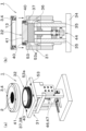
- FIG. 1 is a perspective view of a holding device;
- FIG. FIG. 2 is a cross-sectional view of the holding device.
- FIGS. 3A, 3B, 3C, 3D, 3E, and 3F are explanatory diagrams of the seat retaining ring.
- FIG. 3(a) is an exploded view of the seat retaining ring.
- FIG. 3(b) is a cross-sectional view of the seat holding ring shown in FIG. 3(a) in an exploded state.
- FIG. 3(c) is a perspective view of the elastic sheet sandwiched between the upper ring and the lower ring.
- FIG.3(d) is sectional drawing of the state shown in FIG.3(c).
- FIG. 3(a) is an exploded view of the seat retaining ring.
- FIG. 3(b) is a cross-sectional view of the seat holding ring shown in FIG. 3(a) in an exploded state.
- FIG. 3(c) is a perspective view of the
- FIG. 3(e) is a perspective view of the seat retaining ring with the preload ring attached.
- FIG.3(f) is sectional drawing of the state shown in FIG.3(e).
- FIG. 4 is an enlarged sectional view of the ring portion of the seat retaining ring.
- FIGS. 5(a) and 5(b) are explanatory diagrams immediately before the seat retaining ring is placed on the tension applying device.
- FIG. 5(a) is a perspective view.
- FIG. 5(b) is a cross-sectional view.
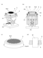
- FIGS. 6(a), 6(b) and 6(c) are explanatory diagrams of a holding device in which a sheet holding ring is attached to a tension applying device.
- FIG. 6(a) is a perspective view.
- FIG. 6(b) is a cross-sectional view.
- FIG. 6(c) is an enlarged sectional view of a shoulder portion provided with a height reference ring and a rotating body.
- FIGS. 7A, 7B, and 7C are explanatory diagrams immediately before inserting the workpiece into the through hole.
- FIG. 7(a) is a perspective view of the holding device in a state in which the through holes of the elastic sheet are expanded.
- FIG. 7(b) is a sectional view of the holding device shown in FIG. 7(a).
- FIG. 7(c) is a perspective view showing the elastic sheet and the work with the through holes expanded.
- FIGS. 8A, 8B, 8C, and 8D are explanatory diagrams of a state in which the workpiece is inserted into the through hole.
- FIG. 8(a) is a perspective view of the holding device.
- FIG. 8(b) is a sectional view of the holding device shown in FIG. 8(a).
- FIG. 8(c) is a perspective view of the elastic sheet in which the work is inserted.
- FIG. 8(d) is an enlarged cross-sectional view of the work and the through hole in which the work is inserted.
- FIGS. 9A, 9B, and 9C are explanatory diagrams of a state in which the work is inserted and the tension is released.
- FIG. 9(a) is a perspective view of the holding device.
- FIG. 9(b) is a cross-sectional view of the holding device shown in FIG. 9(a).
- FIG. 9(a) is a perspective view of the holding device.
- FIG. 9(b) is a cross-sectional view of the holding device shown in FIG. 9(a).
- FIG. 9(c) is an enlarged perspective view of a state in which the work is inserted into the through hole of the elastic sheet.
- 10A and 10B are explanatory diagrams showing a state in which external electrodes are formed on the ends of the workpiece inserted into the through-holes of the elastic sheet.
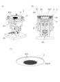
- FIGS. 11A, 11B, and 11C are explanatory diagrams showing the state of recovering works.
- FIG. 11(a) is a cross-sectional view of the device with the seat retaining ring set.
- FIG. 11(b) is a cross-sectional view of the device with tension applied to the elastic sheet.
- FIG. 11(c) is a perspective view of the device with the seat retaining ring removed.
- the work holding device 1 includes an elastic sheet 3 having a plurality of through holes 2 smaller than the thickness of the work W to be processed, and the elastic sheet 3 being spread out. It is roughly composed of a ring-shaped sheet retaining ring 4 for retaining and a tension applying mechanism 5 for applying tension to the elastic sheet 3 attached to the sheet retaining ring 4 in the plane direction.
- the elastic sheet 3 is made of a circular sheet material having elasticity such as silicon rubber, and in the natural state where tension is not applied, when the work W such as a ceramic capacitor is a quadrangular prism, the through hole 2 smaller than that is formed in the center. Many have been established in the area.
- the thickness is set to be slightly shorter than the length of the workpiece W.
- the size of the work W is 0.5 mm x 0.5 mm x 1.0 mm in length x width x length
- the through hole 2 is a slightly smaller rectangle of 0.4 mm x 0.4 mm. is set.
- processing methods such as laser processing, punching processing, and molding can be used.
- the arrangement of the holes can be selected as appropriate, and the elastic sheet 3 shown in the drawing is opened in a grid pattern.
- a ring-shaped sheet retaining ring 4 for mounting and retaining the elastic sheet 3 in a spread state has a circular opening, and a ring body provided with a retaining portion for retaining the elastic sheet outside the opening, and a preloading ring for applying initial tension to the elastic sheet held by the ring body.
- the embodiment of the ring body shown in FIG. An upper ring 12 as a second ring that has an opening hole 12a (that is, an opening) and covers the upper surface of the lower ring 11 to sandwich the elastic sheet 3 therebetween.
- a preloading ring 13 for stretching the elastic sheet 3 sandwiched between the rings 11 is attached from below to be integrated.
- a sandwiching portion 15 is formed on the surface where the upper ring 12 and the lower ring 11 are overlapped with each other, and a recess portion is formed on the lower surface of the lower ring 11 so that the preloading ring 13 is fitted.
- 16 are formed along the inner circumference.
- the preload ring 13 is formed with a ring-shaped flange portion 18 that fits into the recess portion 16 as a mounting portion.
- a ring-shaped standing wall 19 that can be fitted is formed in the vicinity of the inner periphery of 11a.
- the elastic sheet 3 is placed on the lower ring 11 in a naturally spread state, and then covered with the upper ring 12 so that the outer peripheral portion of the elastic sheet 3 is held between both rings 11. , 12, and in this state, the screw 21 is tightened from above to clamp the outer peripheral portion of the elastic sheet 3 between the clamping portions 15 of both rings 11 and 12.
- the elastic sheet 3 is stretched over the plane connecting the inner peripheries of the clamping portion 15 without receiving much tension.
- the standing wall 19 is inserted into the through opening 11a of the lower ring 11 with the preloading ring 13 facing the elastic sheet 3 from below. , the tip of the standing wall 19 is brought into contact with the lower surface of the elastic sheet 3, and is further raised toward the vertical ring 11 side.
- the flange portion 18 of the preload ring 13 is fitted into the recess portion 16 of the lower ring 11 , the height of the standing wall 19 from the upper surface of the flange portion 18 is greater than the dimension from the holding portion 15 to the lower surface of the elastic sheet 3 . is set high (large), the upper peripheral edge of the standing wall 19 pushes up the elastic sheet 3 (see FIG.
- the tension applying mechanism 5 for applying tension to the elastic sheet 3 attached to the seat retaining ring 4 will be described.
- the tension applying mechanism 5 has a seat-side table 31 that moves up and down with the seat retaining ring 4 attached, and a non-moving state regardless of the up-and-down movement of the seat-side table 31. and a thrusting member 32 that maintains and abuts on the elastic sheet 3 to apply tension, in other words, it relatively moves in the axial direction of the sheet holding ring 4 attached to the sheet side table 31 .
- the plunging member 32 is provided on an upper beam 36 connecting the upper ends of left and right uprights 35 erected on a base 34, and is fixed in a circular ring shape slightly smaller than the opening through which the seat retaining ring 4 penetrates.
- a support base 37 is provided, and an outer shoulder portion 38 on the fixed support base 37 (the portion corresponding to the position where the elastic sheet 3 comes into contact when it enters the opening of the seat retaining ring 4) is provided with a height reference ring as a tension applying member.
- a plurality of rotating bodies 40 are arranged in circular positions just outside the height reference ring 39, and a through hole 2 of the elastic sheet 3 is opened inside the height reference ring 39.
- a round seating cradle 41 is provided which is slightly wider than the area covered by the seat.
- the plurality of rotating bodies 40 have a smaller diameter than the inner diameter of the opening of the seat retaining ring 4, and are arranged at the same height on the shoulder portion of the height reference ring 39 on which the elastic sheet 3 contacts. 40 is arranged parallel to the tangential direction of the circumference of the fixed support base 37, and is configured to be individually rotatable.
- the fixed support base 37, the outer shoulder portion 38, the height reference ring 39, the row of the rotating bodies 40, and the seating base 41 are arranged on a concentric circle, and are also positioned on a concentric circle with the seat retaining ring 4. .
- the height reference ring 39 regulates the position of the lower surface of the elastic sheet 3 (that is, the surface on the plunge member 32 side) regardless of the vertical position of the seat retaining ring 4. It is a member that regulates the height (gap) from the upper surface to the lower surface of the elastic sheet 3 . Specifically, as shown in FIG. 6(c), it is a wall-shaped circular ring rising from the fixed support base 37 inside the row of the lower rotating bodies 40, and the upper end (tip) of the circular shape is an elastic sheet.
- the rotating body 40 can smoothly and efficiently change the direction of the tension applied to the elastic sheet 3, and when arranged on the concentric circles as described above, the tension is applied evenly in the radial direction from the center of the concentric circles. It is possible to make the elongation of the elastic sheet 3 uniform and prevent distortion. Therefore, each through hole 2 can be expanded while maintaining a similar shape.
- the rotating body 40 may be a member such as a ball bearing, a roller bearing, or a roller that can be easily rotated with little resistance and that can change the direction of tension.
- the seating support base 41 is located at a position adapted to the work W, in the above embodiment, at a position where a gap of 0.25 mm is formed. are placed in In addition, upper and lower through-holes are formed in the above-described seating support base 41, for example, at positions whose phases are changed by 90 degrees in the circumferential direction. It may be configured to project slightly from the surface of 41 and support from below so that the elastic sheet 3 is not bent (not shown).
- the seating base 41 may be configured to be movable up and down so that the distance between it and the elastic sheet 3 can be adjusted together with the height reference ring 39 according to the size of the work W.
- a magnetic force generating means such as an electromagnet is provided on the back side of the seating surface of the seating base 41, and in the case of a workpiece containing a magnetic material, a magnetic force is applied to the workpiece so that it can be guided to the through hole 2 of the elastic sheet 3. good too.
- a drive mechanism 44 for vertically moving the seat side table 31 is arranged between the left and right uprights 35 .
- a bearing 47 is provided on the lower beam portion 46 connecting the lower portions of the left and right uprights 35, and an elevation drive shaft 48 is provided in the bearing 47 so as to pass therethrough.
- a stepped belt 50 is stretched between a pulley 49 attached to 48 and a pulley (not shown) of a drive motor, and a male screw portion of an elevation drive shaft 48 projecting above the bearing 47 is attached to a seat side table 31 to be described later.
- the seat-side table 31 is configured to move vertically by rotating the elevation drive shaft 48 with a drive motor.
- the sheet side table 31 includes a mounting table 53 having a through opening 53a larger than the upper portion of the thrust member 32 and on which the sheet holding ring 4 is placed, and leg pieces extending downward from both sides of the mounting table 53. 54 and a horizontal beam 55 connecting the upper and lower portions of the leg piece 54 to the left and right. A guide portion 57 is provided between the piece 54 and the upright 35 . For this reason, as described above, when the drive motor rotates the elevation drive shaft 48 in one direction, the female screw portion 56 moves upward, and the leg piece 54 is guided by the guide portion 57 and ascends. The female screw portion 56 moves downward, and the leg piece 54 is guided by the guide portion 57 and descends.
- the mounting table 53 of the sheet-side table 31 is provided with clamping tools 58 at four corners of the rectangular mounting table 53. The clamping tools 58 are used to hold the sheet placed at a predetermined position. It is configured to clamp the retaining ring 4 .
- the elastic sheet 3 is prepared.
- the elastic sheet 3 is provided with a large number of through holes 2 smaller than the thickness of the workpiece W to be processed. Specifically, if the workpiece W has a square column with a side of 0.5 mm and a length of 1.0 mm, rectangular square holes with a size of 0.4 mm are formed in a grid pattern in a natural state without applying tension. It is a silicon rubber sheet with a thickness of 0.55 mm.
- the elastic sheet 3 is placed between the upper ring 12 and the lower ring 11 in a natural state, and the outer peripheral portion of the elastic sheet 3 is sandwiched.
- the ring 12 and the lower ring 11 are fastened.
- the flange portion 18 of the preload ring 13 is fitted into the recess portion 16 of the lower ring 11 from below, and the standing wall 19 erected from the flange portion 18 is brought into contact with the lower surface of the elastic sheet 3 so that the elastic sheet 3 is substantially
- This first state is maintained by slightly pushing up most of it to apply a weak tension and tightening the four screws 22 from below. Since the tension (preload) is very slight in this first state, the size of the through hole 2 is about 0.44 mm on a side and about 0.5 mm in thickness.
- the sheet holding ring 4 is set on the work holding device 1 and the tension applying mechanism 5 applies tension to the elastic sheet 3 to expand the through hole 2 .
- the seat-retaining ring 4 is moved so that the row of rotating bodies 40 enters the opening of the preloading ring 13 . 4 is lowered from above to a predetermined position and clamped by a clamp tool 58. - ⁇ In this state, the upper end of the height reference ring 39 is in contact with the lower surface of the elastic sheet 3 as shown in FIG. there is
- the seat side table 31 is gradually lowered by driving the drive motor from the initial state described above. Then, the row of rotating bodies 40 arranged in a circular shape hits the lower surface of the elastic sheet 3, and when the seat-side table 31 is further lowered, the row of rotating bodies 40 moves the elastic sheet 3 relatively, as shown in FIG. Tension is applied to the elastic sheet 3 by pushing it up. Even when this state is changed, the distance between the lower surface of the elastic sheet 3 and the upper surface of the seating base 41 is maintained at the initial specified dimension by the height reference ring 39 .
- each through-hole 2 is expanded. Specifically, when tension is applied until the thickness of the elastic sheet 3 becomes about 0.38 mm, the size of the through hole 2 is expanded to 0.6 mm on one side, and the work W enters the second state. (hole expansion step).
- a large number of works W are supplied from above and inserted into the expanded through-holes 2 (work insertion step).
- the work W may be inserted by aligning the work W with the position of the through-hole 2 using a parts feeder (feeder mechanism).
- a parts feeder feeder mechanism
- the parts feeder is not shown in the drawing, for example, when inserting an elastic sheet in the horizontal direction, vibration is generated in a spiral passage formed diagonally upward on the inner peripheral surface of the ball of the parts feeder.
- the workpieces are lined up one by one by applying a force, and are advanced in the passage formed linearly from the inclined upper end of the passage.
- a configuration may be employed in which the work is delivered and inserted into the through-holes 2 , and this inserting operation is sequentially performed while moving to insert the work into all the through-holes 2 .
- a plurality of rows of passages may be provided, and a configuration may be adopted in which the liquid is delivered from a plurality of outlets at once and inserted into through-holes at a plurality of locations.
- the passage may be singular or plural.
- the parts feeder may be provided with a single row or multiple rows of passages.
- the work W may be supplied onto the elastic sheet 3 from a hopper or stocker (supply hopper mechanism) and dropped into the through hole 2 .
- a vibration adding mechanism such as a vibrator, it can be inserted efficiently.
- the work W contains a magnetic material
- a magnet is arranged under the seating surface of the seating base 41 and magnetic force is used. You may try to attract them positively.
- the magnetic force is applied in this way, the work can be efficiently drawn into the through hole, and the end of the work can be reliably brought into contact with the upper surface of the seating table 41, so that the accuracy of the projection length of the work can be improved. can be enhanced.
- a configuration may be employed in which the works are transferred to the adhesive pallet in a state of being arranged at predetermined positions, and these works are inserted at the same time. With this configuration, the work can be efficiently put into the through hole.
- the seating base 41 When the workpiece W is inserted into the through hole 2 as described above, the seating base 41 is disposed below the elastic sheet 3, and the upper surface of the seating base 41 and the lower surface of the elastic sheet 2 are aligned. Since the interval is maintained at 0.25 mm by the height reference ring 39 , the lower end of the work W inserted into the expanded through hole 2 is supported by the seating base 41 and the lower end is placed on the lower surface of the elastic sheet 3 . , and the upper end of the elastic sheet 3 protrudes from the upper surface of the elastic sheet 3 and stops. In this embodiment, both the upper end and the lower end of the work W protrude by 0.25 mm.
- the sheet-side table 31 is lifted to return to the initial state, as shown in FIG. Then, the tension applied to the elastic sheet 3 is released, and the elastic force of the elastic sheet 3 causes the through hole 2 to contract.
- the workpiece W is held in close contact. In this state, the clamp tool 58 is loosened, the sheet holding ring 4 is removed, and the work W is held in the through hole 2, and the next step can be performed.
- the sheet holding ring 4 is placed in the chamber and processed such as vapor deposition or sputtering.
- the metal film is formed on the end portion of the work W in this way, the inner surface of each through hole 2 of the elastic sheet 3 is in close contact with the intermediate portion of the work W without gaps, and only the end portion of the work W protrudes.
- the external electrodes can be formed only on the projecting end portions, and the external electrodes can be formed on five surfaces including the end surfaces without steps.
- the tension is only slightly reduced, and it is possible to prevent the formation of a gap between the inner surface of the through-hole and the work. Therefore, deterioration of the masking function during processing can be prevented in advance, and high-quality processing can be performed.
- the preloading can disperse and absorb the bending and distortion of the elastic sheet 3 . Therefore, it is possible to prevent problems such as the workpiece coming out of the through-hole 2 or slipping.
- This workpiece recovery device 61 has substantially the same configuration as the holding device 1 described above, but has a recovery space 62 in place of the seating base 41 .
- the sheet holding ring 4 is placed on the mounting table 53 and fixed by the clamping tool 58, and the mounting table 53 is lowered to clear the through hole 2. Expand. Then, the work W in the through-hole 2 drops and can be recovered in the recovery space 62 .
- the elastic sheet 3 is vibrated, the work W is pressed downward by a pressing tool 63 from above (see FIG. 11(b)), or the inside of the recovery space 62 is depressurized, thereby causing the work W to move. Efficient recovery can be achieved by facilitating separation from the elastic sheet.
- a magnetic force may be applied from one side of the elastic sheet holding the work toward the other side, and the work may be ejected by the magnetic force.
- the elastic sheet from which the work has been discharged can be reused after being cleaned.
- the workpiece recovery device 61 may be used as a device by removing the seating support 41 of the holding device 1 and attaching a member having the recovery space 62 to that portion. In short, the work can be efficiently taken out (discharged) by applying a pressing force or a suction force to the work from one side of the elastic sheet to the other to facilitate detachment.
- the workpiece W to be processed is not limited to the above-described quadrangular prism, but may be a cylinder or a polygon, as long as it has a shape that can be inserted into the through hole 2 . Also, the work W may be put in with the sheet oriented in the vertical direction.
- the tension applying mechanism includes a seat-side table on which a seat-retaining ring is attached, and an entry-side table that moves relatively in the axial direction of the seat-retaining ring attached to the seat-side table to expand the through-hole of the elastic sheet.
- the seat retaining ring is not limited to a structure in which it is divided into upper and lower parts, and it is sufficient that it can be mounted in a state in which the elastic sheet is spread out.
Landscapes
- Engineering & Computer Science (AREA)
- Power Engineering (AREA)
- Manufacturing & Machinery (AREA)
- Microelectronics & Electronic Packaging (AREA)
- Mechanical Engineering (AREA)
- Jigs For Machine Tools (AREA)
- Fixed Capacitors And Capacitor Manufacturing Machines (AREA)
Priority Applications (2)
| Application Number | Priority Date | Filing Date | Title |
|---|---|---|---|
| KR1020247029614A KR102912923B1 (ko) | 2022-02-15 | 2023-01-19 | 가공물 보유용의 탄성 시트, 시트 보유환, 가공물의 보유 장치, 가공물의 보유 방법, 및 가공물의 배출 방법 |
| CN202380021492.XA CN118696388A (zh) | 2022-02-15 | 2023-01-19 | 工件保持用的弹性片、片保持环、工件的保持装置、工件的保持方法、以及工件的排出方法 |
Applications Claiming Priority (2)
| Application Number | Priority Date | Filing Date | Title |
|---|---|---|---|
| JP2022-021051 | 2022-02-15 | ||
| JP2022021051A JP2023118219A (ja) | 2022-02-15 | 2022-02-15 | ワーク保持用の弾性シート、シート保持環、ワークの保持装置、ワークの保持方法、およびワークの排出方法 |
Publications (1)
| Publication Number | Publication Date |
|---|---|
| WO2023157555A1 true WO2023157555A1 (ja) | 2023-08-24 |
Family
ID=87578363
Family Applications (1)
| Application Number | Title | Priority Date | Filing Date |
|---|---|---|---|
| PCT/JP2023/001537 Ceased WO2023157555A1 (ja) | 2022-02-15 | 2023-01-19 | ワーク保持用の弾性シート、シート保持環、ワークの保持装置、ワークの保持方法、およびワークの排出方法 |
Country Status (4)
| Country | Link |
|---|---|
| JP (1) | JP2023118219A (https=) |
| KR (1) | KR102912923B1 (https=) |
| CN (1) | CN118696388A (https=) |
| WO (1) | WO2023157555A1 (https=) |
Cited By (1)
| Publication number | Priority date | Publication date | Assignee | Title |
|---|---|---|---|---|
| CN120734718A (zh) * | 2025-09-02 | 2025-10-03 | 湖南华湘精密科技发展有限公司 | 一种立式刀库盘加工辅助装置 |
Families Citing this family (1)
| Publication number | Priority date | Publication date | Assignee | Title |
|---|---|---|---|---|
| CN119326231A (zh) * | 2023-10-27 | 2025-01-21 | 永艺家具股份有限公司 | 一种遇阻检测立柱及其使用方法 |
Citations (11)
| Publication number | Priority date | Publication date | Assignee | Title |
|---|---|---|---|---|
| JPS61296706A (ja) * | 1985-06-26 | 1986-12-27 | 関西日本電気株式会社 | セラミツク電子部品の製造方法 |
| JPS63138985A (ja) * | 1986-12-01 | 1988-06-10 | 松下電器産業株式会社 | 電子部品保持体 |
| JPH0590791A (ja) * | 1991-09-26 | 1993-04-09 | Japan Tobacco Inc | ワーク実装機 |
| JPH07122583A (ja) * | 1993-10-26 | 1995-05-12 | Fujitsu Ltd | 半導体装置の製造方法及び半導体製造装置 |
| JPH0922845A (ja) * | 1995-07-07 | 1997-01-21 | Taiyo Yuden Co Ltd | 電子部品の外部電極形成方法 |
| JPH09183029A (ja) * | 1995-12-28 | 1997-07-15 | Taiyo Yuden Co Ltd | ワーク抜取方法及びその装置 |
| JP2003303741A (ja) * | 2002-04-05 | 2003-10-24 | Murata Mfg Co Ltd | 電子部品取扱い装置および電子部品取扱い方法 |
| JP2006321591A (ja) * | 2005-05-18 | 2006-11-30 | Taiyo Yuden Co Ltd | チップ状電子部品素子の外部電極形成方法及び装置 |
| JP2007123658A (ja) * | 2005-10-31 | 2007-05-17 | Disco Abrasive Syst Ltd | 粘着テープの拡張装置 |
| JP2007153477A (ja) * | 2005-12-01 | 2007-06-21 | Murata Mfg Co Ltd | 電子部品測定装置及びその制御方法 |
| JP2009176767A (ja) * | 2008-01-21 | 2009-08-06 | Tdk Corp | 積層セラミックコンデンサの製造方法 |
Family Cites Families (4)
| Publication number | Priority date | Publication date | Assignee | Title |
|---|---|---|---|---|
| US4561954A (en) * | 1985-01-22 | 1985-12-31 | Avx Corporation | Method of applying terminations to ceramic bodies |
| JPH046812A (ja) | 1990-04-24 | 1992-01-10 | Tama Electric Co Ltd | チップ部品電極形成方法 |
| JP2000348971A (ja) * | 1999-06-04 | 2000-12-15 | Matsushita Electric Ind Co Ltd | 積層体の製造方法及び積層体の製造装置 |
| JP2009296706A (ja) * | 2008-06-02 | 2009-12-17 | Toshiba Corp | 電動機制御装置 |
-
2022
- 2022-02-15 JP JP2022021051A patent/JP2023118219A/ja active Pending
-
2023
- 2023-01-19 KR KR1020247029614A patent/KR102912923B1/ko active Active
- 2023-01-19 CN CN202380021492.XA patent/CN118696388A/zh active Pending
- 2023-01-19 WO PCT/JP2023/001537 patent/WO2023157555A1/ja not_active Ceased
Patent Citations (11)
| Publication number | Priority date | Publication date | Assignee | Title |
|---|---|---|---|---|
| JPS61296706A (ja) * | 1985-06-26 | 1986-12-27 | 関西日本電気株式会社 | セラミツク電子部品の製造方法 |
| JPS63138985A (ja) * | 1986-12-01 | 1988-06-10 | 松下電器産業株式会社 | 電子部品保持体 |
| JPH0590791A (ja) * | 1991-09-26 | 1993-04-09 | Japan Tobacco Inc | ワーク実装機 |
| JPH07122583A (ja) * | 1993-10-26 | 1995-05-12 | Fujitsu Ltd | 半導体装置の製造方法及び半導体製造装置 |
| JPH0922845A (ja) * | 1995-07-07 | 1997-01-21 | Taiyo Yuden Co Ltd | 電子部品の外部電極形成方法 |
| JPH09183029A (ja) * | 1995-12-28 | 1997-07-15 | Taiyo Yuden Co Ltd | ワーク抜取方法及びその装置 |
| JP2003303741A (ja) * | 2002-04-05 | 2003-10-24 | Murata Mfg Co Ltd | 電子部品取扱い装置および電子部品取扱い方法 |
| JP2006321591A (ja) * | 2005-05-18 | 2006-11-30 | Taiyo Yuden Co Ltd | チップ状電子部品素子の外部電極形成方法及び装置 |
| JP2007123658A (ja) * | 2005-10-31 | 2007-05-17 | Disco Abrasive Syst Ltd | 粘着テープの拡張装置 |
| JP2007153477A (ja) * | 2005-12-01 | 2007-06-21 | Murata Mfg Co Ltd | 電子部品測定装置及びその制御方法 |
| JP2009176767A (ja) * | 2008-01-21 | 2009-08-06 | Tdk Corp | 積層セラミックコンデンサの製造方法 |
Cited By (1)
| Publication number | Priority date | Publication date | Assignee | Title |
|---|---|---|---|---|
| CN120734718A (zh) * | 2025-09-02 | 2025-10-03 | 湖南华湘精密科技发展有限公司 | 一种立式刀库盘加工辅助装置 |
Also Published As
| Publication number | Publication date |
|---|---|
| KR20240144340A (ko) | 2024-10-02 |
| JP2023118219A (ja) | 2023-08-25 |
| CN118696388A (zh) | 2024-09-24 |
| KR102912923B1 (ko) | 2026-01-14 |
Similar Documents
| Publication | Publication Date | Title |
|---|---|---|
| WO2023157555A1 (ja) | ワーク保持用の弾性シート、シート保持環、ワークの保持装置、ワークの保持方法、およびワークの排出方法 | |
| US7470120B2 (en) | Configurable die detachment apparatus | |
| US8470130B2 (en) | Universal die detachment apparatus | |
| US3851758A (en) | Semiconductor chip fixture | |
| US7969026B2 (en) | Flexible carrier for high volume electronic package fabrication | |
| KR102152009B1 (ko) | 볼 탑재 장치 | |
| US12455600B2 (en) | Fixing unit and heat dissipation device using same | |
| EP0798955A1 (en) | Method of and apparatus for peeling off chips | |
| TWI831174B (zh) | 基板清洗裝置及其控制方法 | |
| US7028396B2 (en) | Semiconductor chip pick and place process and equipment | |
| CN111128840B (zh) | 晶片的扩展方法和晶片的扩展装置 | |
| JP2023118219A5 (https=) | ||
| JP2004174595A (ja) | 加工装置及び方法 | |
| JP4863350B2 (ja) | 粘着性シート及び保持治具 | |
| JP5652868B2 (ja) | ウエハパレット及び部品実装機並びにダイシングシートの取付方法 | |
| US7762446B2 (en) | Method and device for transferring a solder deposit configuration | |
| JP6895300B2 (ja) | スラストころ軸受の組立方法および組立装置 | |
| CN120283301A (zh) | 焊料体处理工具及利用其的焊料体处理方法 | |
| JP3245961B2 (ja) | チップ突き上げ装置 | |
| TWI919155B (zh) | 焊料體處理工具及利用其的焊料體處理方法 | |
| CN111128839B (zh) | 晶片的扩展方法和晶片的扩展装置 | |
| US20210134648A1 (en) | Technique for handling diced wafers of integrated circuits | |
| CN217572633U (zh) | 壳体件的固定工装 | |
| CN222826390U (zh) | 晶圆弹匣放置机构及具有其的内引脚接合装置 | |
| CN222403295U (zh) | 压铆治具 |
Legal Events
| Date | Code | Title | Description |
|---|---|---|---|
| 121 | Ep: the epo has been informed by wipo that ep was designated in this application |
Ref document number: 23756083 Country of ref document: EP Kind code of ref document: A1 |
|
| WWE | Wipo information: entry into national phase |
Ref document number: 202380021492.X Country of ref document: CN |
|
| ENP | Entry into the national phase |
Ref document number: 20247029614 Country of ref document: KR Kind code of ref document: A |
|
| WWE | Wipo information: entry into national phase |
Ref document number: 1020247029614 Country of ref document: KR |
|
| NENP | Non-entry into the national phase |
Ref country code: DE |
|
| 122 | Ep: pct application non-entry in european phase |
Ref document number: 23756083 Country of ref document: EP Kind code of ref document: A1 |