WO2023157380A1 - ロボット監視システム、監視装置、監視装置の制御方法およびプログラム - Google Patents
ロボット監視システム、監視装置、監視装置の制御方法およびプログラム Download PDFInfo
- Publication number
- WO2023157380A1 WO2023157380A1 PCT/JP2022/039390 JP2022039390W WO2023157380A1 WO 2023157380 A1 WO2023157380 A1 WO 2023157380A1 JP 2022039390 W JP2022039390 W JP 2022039390W WO 2023157380 A1 WO2023157380 A1 WO 2023157380A1
- Authority
- WO
- WIPO (PCT)
- Prior art keywords
- robot
- motion
- monitoring
- control unit
- timing
- Prior art date
- Legal status (The legal status is an assumption and is not a legal conclusion. Google has not performed a legal analysis and makes no representation as to the accuracy of the status listed.)
- Ceased
Links
Images


Classifications
-
- B—PERFORMING OPERATIONS; TRANSPORTING
- B25—HAND TOOLS; PORTABLE POWER-DRIVEN TOOLS; MANIPULATORS
- B25J—MANIPULATORS; CHAMBERS PROVIDED WITH MANIPULATION DEVICES
- B25J9/00—Program-controlled manipulators
- B25J9/16—Program controls
- B25J9/1674—Program controls characterised by safety, monitoring, diagnostic
-
- B—PERFORMING OPERATIONS; TRANSPORTING
- B25—HAND TOOLS; PORTABLE POWER-DRIVEN TOOLS; MANIPULATORS
- B25J—MANIPULATORS; CHAMBERS PROVIDED WITH MANIPULATION DEVICES
- B25J19/00—Accessories fitted to manipulators, e.g. for monitoring, for viewing; Safety devices combined with or specially adapted for use in connection with manipulators
- B25J19/06—Safety devices
-
- B—PERFORMING OPERATIONS; TRANSPORTING
- B25—HAND TOOLS; PORTABLE POWER-DRIVEN TOOLS; MANIPULATORS
- B25J—MANIPULATORS; CHAMBERS PROVIDED WITH MANIPULATION DEVICES
- B25J9/00—Program-controlled manipulators
- B25J9/16—Program controls
- B25J9/1694—Program controls characterised by use of sensors other than normal servo-feedback from position, speed or acceleration sensors, perception control, multi-sensor controlled systems, sensor fusion
- B25J9/1697—Vision controlled systems
Definitions
- the present invention relates to a robot monitoring system that monitors the motion of a robot, a monitoring device that monitors the motion of a robot, a control method for the monitoring device, and a program that causes the monitoring device to perform a predetermined function.
- robots have been used in fields such as factory automation.
- a robot arm is installed near the belt conveyor.
- the robot arm transfers, for example, an article loaded at a predetermined position to a container on a belt conveyor according to a preset control command.
- Patent Document 1 describes a method for detecting that an abnormality has occurred in a robot during its operation.
- a camera is installed to overlook the motion range of the robot.
- An image acquired by the camera is compared with a simulated image of the robot position as seen from the camera direction. If the two images differ by more than a predetermined amount, it is determined that an anomaly has occurred in the robot's motion.
- so-called occlusion may occur in the imaging direction of the camera, for example, the robot's hand is hidden behind the arm.
- Such occlusion is particularly likely to occur when the installation positions of the cameras are subject to certain restrictions, such as when imaging a plurality of robots with one camera.
- the hand is not captured in the camera image, so even if the camera image and the simulation image are compared, it is not possible to properly determine whether the hand is malfunctioning.
- the present invention provides a robot monitoring system, a monitoring device, and a control method for a monitoring device that can appropriately and accurately determine an abnormal operation of a robot even if occlusion occurs in the monitored object in the captured image of the robot. and to provide programs.
- a first aspect of the present invention relates to a robot monitoring system.
- a robot monitoring system includes at least a camera that captures an action range of a robot, and a monitoring device that monitors the action of the robot based on an image captured by the camera.
- the monitoring device includes a storage unit, a control unit, and a communication unit that communicates with the robot and the camera.
- the storage unit stores a table in which a series of motion positions to which the monitoring target of the robot moves and time information regarding the timing at which the monitoring target is positioned at each motion position are associated with each other.
- the control unit compares the motion position of the monitored object obtained from the robot via the communication unit with the motion position of the monitored object based on the captured image obtained from the camera via the communication unit.
- the robot monitoring system it is possible to determine whether the robot is malfunctioning by the first determination process using the captured image of the robot.
- a second aspect of the present invention relates to a monitoring device that monitors the motion of a robot.
- a monitoring device includes a storage unit, a control unit, and a communication unit that communicates with the robot and at least a camera that captures an action range of the robot.
- the storage unit stores a table in which a series of motion positions to which the monitoring target of the robot moves and time information regarding the timing at which the monitoring target is positioned at each motion position are associated with each other.
- the control unit compares the motion position of the monitored object obtained from the robot via the communication unit with the motion position of the monitored object based on the captured image obtained from the camera via the communication unit.
- a third aspect of the present invention relates to a control method for a monitoring device that monitors the motion of a robot.
- the monitoring device associates a series of motion positions to which the monitored object of the robot moves with time information regarding the timing at which the monitored target is positioned at each of the motion positions.
- a method for controlling a monitoring device includes the steps of: obtaining an operation position of the object to be monitored from the robot via a communication unit; and obtaining a captured image from a camera that captures at least an operation range of the robot via the communication unit.
- a fourth aspect of the present invention relates to a program that causes a control unit of a monitoring device that monitors the motion of a robot to execute a predetermined function.
- the program according to this aspect includes a table in which a series of motion positions to which the monitored target of the robot moves and time information regarding the timing at which the monitored target is positioned at each of the motion positions are associated with each other.
- the program has a function of acquiring the operating position of the monitoring target from the robot via the communication unit, a function of acquiring a captured image from a camera that captures at least the operating range of the robot through the communication unit, and a function of acquiring a captured image from the robot through the communication unit.
- the control unit is caused to perform a function of comparing the acquired timing with the timing based on the time information associated with the motion position in the table, and determining an operation abnormality of the robot.
- the robot monitoring system, the monitoring device, and the control of the monitoring device are capable of appropriately and accurately judging an abnormal operation of the robot even if occlusion occurs in the monitored object in the captured image of the robot.
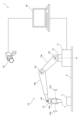
- FIG. 1 is a diagram schematically showing a usage pattern of a robot monitoring system according to an embodiment.
- FIG. 2 is a block diagram showing configurations of a robot arm, a camera, and a monitoring device according to the embodiment.
- FIG. 3 is a diagram illustrating the configuration of a table stored in a storage unit of the monitoring device according to the embodiment;
- FIG. 4 is a diagram schematically showing the relationship between the field of view of the camera and the orthogonal coordinate system of the robot arm, according to the embodiment.
- FIG. 5 is a flowchart showing processing performed by the control unit when the robot arm actually operates according to the embodiment.
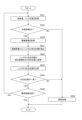
- FIG. 6 is a flowchart showing monitoring processing in the control unit of the monitoring device according to the embodiment.
- FIG. 7 is a flowchart showing another monitoring process in the control unit of the monitoring device according to the embodiment.
- FIG. 8 is a diagram showing the structure of a table stored in the storage unit of the monitoring device according to the modification.
- FIG. 9 is a flowchart showing monitoring processing in the control unit of the monitoring device according to the modification.
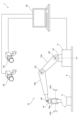
- FIG. 10 is a diagram schematically showing a usage pattern of the robot monitoring system 1 according to another modification.
- FIG. 11 is a flowchart showing monitoring processing in the control unit of the monitoring device according to another modification.
- FIG. 1 is a diagram schematically showing a usage pattern of a robot monitoring system 1 according to an embodiment.
- the robot monitoring system 1 monitors the motion of the robot arm 10.
- a robot arm 10 is installed near the belt conveyor 4 .
- the robot arm 10 transfers the article 3 loaded at a predetermined position to the container 2 on the belt conveyor 4 .
- the robot arm 10 includes a base 11 , a support 12 , arms 13 a and 13 b and a hand 14 .
- the base 11 is installed on the side of the belt conveyor 4.
- the support base 12 is installed on the base 11 so as to be rotatable about a rotation axis A1 parallel to the vertical direction.
- the arm 13a is installed on the support base 12 so as to be rotatable about a rotation axis A2 parallel to the horizontal direction.
- the arm 13b is installed at the end of the arm 13a so as to be rotatable about a rotation axis A3 parallel to the horizontal direction.
- the hand 14 is installed at the end of the arm 13b so as to be rotatable about a horizontally parallel rotating shaft A4.
- the hand 14 has a plurality of claws 14a for gripping the article 3. As shown in FIG.
- the robot arm 10 includes a plurality of drive mechanisms for rotating the support base 12, the arms 13a and 13b, and the hand 14 about the rotation axes A1 to A4.
- the robot arm 10 can three-dimensionally move the hand 14 by driving the motors that are the driving sources of these drive mechanisms.
- the hand 14 also has a driving mechanism for opening and closing the plurality of claws 14a.
- the robot arm 10 can grip and release the article 3 by driving the motor that is the drive source of the drive mechanism.
- a control command for operating the hand 14 within a predetermined operating range is set in the robot arm 10 in advance.
- the control command includes the drive amount of each drive mechanism (motor) for moving the hand 14 from the initial position to the target position and returning from the target position to the initial position. More specifically, with respect to a plurality of positions (nodes) on the movement trajectory of the hand 14, the drive amount of each drive mechanism (motor) for moving the hand 14 to the node is determined sequentially from the initial position node. is set to
- the control command includes a command for opening and closing the claw 14a of the hand 14 at the target position in addition to the control amount.
- control commands are set in the robot arm 10 by the user via the monitoring device 30, for example.
- the above control command may be set in the robot arm 10 via a terminal other than the monitoring device 30 .
- the robot monitoring system 1 includes a camera 20, a monitoring device 30, and object sensors 41a and 41b.
- the camera 20 captures at least the motion range of the robot arm 10 .
- the camera 20 is installed at a position where the robot arm 10 can be viewed from above.
- the monitoring device 30 is connected to communicate with the camera 20 and the object sensors 41a and 41b via communication lines. Communication between the monitoring device 30 and the cameras and object sensors 41a and 41b may be performed by wireless communication instead of the communication line.
- the monitoring device 30 monitors the motion of the robot arm 10 based on the image captured by the camera 20 and the detection results of the object sensors 41a and 41b. Monitoring control of the robot arm 10 will be described later with reference to FIGS. 6 and 7. FIG.
- the object sensors 41a and 41b detect that the hand 14 has reached a predetermined monitoring position set within the movement range of the hand 14.
- the monitoring position is set, for example, at the target position described above.
- the monitoring position is not limited to one position, and may be set at a plurality of positions within the operating range.
- the object sensors 41a and 41b are composed of infrared sensors.
- the infrared rays emitted from the object sensor 41a are received by the object sensor 41b.
- the infrared rays emitted from the object sensor 41a are not received by the object sensor 41b. Therefore, whether or not the hand 14 has reached the monitoring position can be detected depending on whether or not the object sensor 41b outputs a signal corresponding to the reception of infrared rays.
- FIG. 2 is a block diagram showing the configuration of the robot arm 10, camera 20 and monitoring device 30.
- the robot arm 10 includes a control section 101, an arm drive section 102, a hand drive section 103, and a communication section 104.
- the control unit 101 has a microcomputer and controls each unit according to a program held in an internal memory. The control commands described above are held in the memory within the control unit 101 .
- the control unit 101 may be configured by an FPGA (Field Programmable Gate Array) or the like.
- the arm drive unit 102 includes the above-described motor and drive mechanism for driving the arms 13a and 13b.
- the hand drive unit 103 includes the above-described motor and drive mechanism for driving the hand 14 and the claw 14a of the hand 14 .
- the communication unit 104 is a communication interface for communicating with the monitoring device 30 .
- the communication unit 104 communicates with the communication unit 305 of the monitoring device 30 under the control of the control unit 101 .
- the camera 20 includes a control unit 201, an imaging unit 202, and a communication unit 203.
- the control unit 201 is composed of, for example, a microcomputer or the like, and controls each unit according to a program stored in an internal memory.
- the imaging unit 202 includes an imaging lens and an imaging element, and performs imaging of the visual field area under the control of the control unit 201 .
- the communication unit 203 is a communication interface for communicating with the monitoring device 30 .
- the communication unit 203 communicates with the monitoring device 30 under the control of the control unit 201 .
- the monitoring device 30 includes a control unit 301 , a storage unit 302 , a display unit 303 , an input unit 304 and a communication unit 305 .
- Monitoring device 30 is configured by, for example, a general-purpose personal computer. Monitoring device 30 may be a dedicated product.
- the control unit 301 includes an arithmetic processing circuit such as a CPU (Central Processing Unit), and controls each unit according to a program stored in the storage unit 302.
- the storage unit 302 includes storage media such as ROM, RAM, and hard disk, and stores programs executed by the control unit 301 and various data. Further, the storage unit 302 is used as a work area when the control unit 301 performs control.
- the display unit 303 has a display such as a liquid crystal panel, and displays predetermined information under the control of the control unit 301 .
- the input unit 304 includes input means such as a mouse and a keyboard.
- the communication unit 305 is a communication interface for communicating with the robot arm 10, the camera 20, and the object sensors 41a and 41b. The communication unit 305 communicates with the robot arm 10, the camera 20, and the object sensors 41a and 41b under the control of the control unit 201.
- FIG. 3 is a diagram showing the configuration of a table stored in the storage unit 302 of the monitoring device 30. As shown in FIG.
- the table contains the nodes set on the movement trajectory of the hand 14, the control amount for positioning the hand 14 at each node, and the three-dimensional position of the hand 14 when the hand 14 is positioned at each node (hand position) and the required time required for the hand 14 to be positioned at each node are associated with each other.
- control amount is the amount of rotation by which the support base 12 and the arms 13a and 13b are rotated about the rotation axes A1, A2 and A3 in FIG. Specifically, the amount of rotation from the initial position of each motor that serves as a drive source for these rotations is defined as the control amount.
- each motor is a stepping motor, each number of steps from the initial position is defined as each control amount.
- the hand position is defined as a coordinate point of an orthogonal coordinate system with the installation position of the robot arm 10 as the origin.
- the X and Y axes of the Cartesian coordinate system are parallel to the horizontal plane, and the Z axis is parallel to the vertical direction.
- the origin of the orthogonal coordinate system is set, for example, at the intersection of the upper surface of the base 11 in FIG. 1 and the rotation axis A1.
- the required time is defined as the time required for the hand 14 to reach each node from the initial position during normal operation. That is, the time required for the hand 14 to reach each node from the initial position when the robot arm 10 moves without being restricted by an unexpected obstacle or the like is the required time specified for each node. It's time.
- the hand 14 sequentially moves from the first node N0 to nodes N1, N2, .
- the table defines movement positions to which the hand 14 moves sequentially and the required time to reach those positions during normal operation of the hand 14 .
- FIG. 4 is a diagram schematically showing the relationship between the field of view of the camera 20 and the orthogonal coordinate system of the robot arm 10.
- the camera 20 is installed so that the origin of the orthogonal coordinate system is included within the viewing angle ⁇ of the camera 20 . Further, the camera 20 is installed so that the motion trajectory L10 (motion range) of the hand 14 is included within the range of the viewing angle ⁇ .
- the hand 14 moves from the initial position P0 to the target position P1, and then returns from the target position P1 to the initial position P0.
- the position of the hand 14 is (x1, y1, z1).
- the control unit 301 of the monitoring device 30 Prior to the monitoring operation, the control unit 301 of the monitoring device 30 performs orthogonal A calibration process is executed to associate each coordinate point (X coordinate, Y coordinate, Z coordinate) of the coordinate system with a pixel position on the captured image of the camera 20 . That is, the light rays incident on each pixel are different for each pixel. Therefore, a coordinate point existing on a ray incident on one pixel is associated with the pixel position of the one pixel. Each pixel is associated with a plurality of coordinate points existing on the ray corresponding to the pixel.
- FIG. 5 is a flowchart showing the processing performed by the control unit 101 when the robot arm 10 actually operates.
- the control unit 101 transmits a start notification to the monitoring device 30 via the communication unit 104 (S101).
- the control unit 101 drives the arms 13a and 13b based on the control command described above to move the hand 14 to the next node (S102).
- the control unit 101 transmits the control amount for moving the hand 14 to the node after movement and the coordinate values of the orthogonal coordinate system of the node to the monitoring device via the communication unit 104. 30 (S103).
- the control unit 101 drives the claw 14a of the hand 14 in the closing direction (S105). Further, when the node after movement is at the position to release the grip (S106: YES), the control unit 101 drives the claw 14a of the hand 14 in the opening direction (S107). Then, the control unit 101 determines whether or not the processing for all nodes has been completed (S108). If the determination in step S108 is NO, the control unit 101 returns the process to step S102 to process the next node. In this way, when the processing of one step is completed (S108: YES), the control section 101 ends the processing of FIG.
- FIG. 6 is a flowchart showing monitoring processing in the control unit 301 of the monitoring device 30.
- the control unit 301 receives the start notification transmitted in step S101 of FIG. It is determined whether or not the actual time required for the process has exceeded the standard required time defined in the table of FIG. 3 (S203). More specifically, the control unit 301 extracts the required time (reference required time) corresponding to the control amount and the hand position received in step S201 from the table in FIG. compare. Then, if the difference (time difference) between the two does not exceed a threshold that defines an allowable error (a time lag assumed to occur during normal operation), the control unit 301 determines YES in step S202. exceeds this threshold, the determination in step S202 is NO.
- step S202 determines whether the determination in step S202 is NO. If the determination in step S202 is NO, the control unit 301 assumes that some abnormality has occurred in driving the robot arm 10 and executes abnormality processing (S209). In this abnormality processing, the control unit 301, for example, causes the operation of the robot arm 10 to be urgently stopped, and causes the display unit 303 to display a screen for notifying the abnormality.
- the robot arm 10 When the robot arm 10 comes into contact with an unexpected obstacle, a certain load is applied to the robot arm 10. As a result, the robot arm 10 may move at a slower speed than during normal operation, or may be in a substantially stopped state. When the moving speed of the robot arm 10 is lower than that during normal operation, the determination result in step S202 becomes NO, and the abnormality process is executed in step S209.
- the control unit 301 of the monitoring device 30 determines NO in step S202 even when the control amount and the hand position are not received for a predetermined time or longer in step S201. More specifically, when the control unit 301 does not receive the control amount and the hand position in the next step S201 even after a predetermined period of time has passed after receiving the control amount and the hand position in the previous process of step S201, , the determination in step S202 is NO, and the abnormality processing in step S209 is executed.
- step S202 determines whether the determination in step S202 is YES.
- the control unit 301 advances the process to step S203 and executes monitoring processing based on the captured image acquired from the camera 20.
- the control unit 301 first acquires a captured image captured by the camera 20 at substantially the same timing as when the control amount and the hand position are received (S203).
- the control unit 301 receives captured images from the camera 20 at any time, and temporarily stores the received captured images in the storage unit 302 .
- step S203 the control unit 301 extracts, from the captured images temporarily stored in the storage unit 302, the captured image received at substantially the same timing as the control amount and the hand position received in step S201.
- the control unit 301 acquires the hand position Pa on the captured image corresponding to the hand position acquired in step S201, based on the association defined by the calibration process described above (S204). Also, the control unit 301 extracts the hand position Pb from the captured image acquired in step S203 (S205). In step S205, for example, the control unit 301 executes image analysis processing for extracting the outline of the area of the hand 14 from the captured image. In this case, the control unit 301 extracts the center of gravity of the extracted area as the hand position Pb. Alternatively, when the hand 14 is marked, the control unit 301 extracts the marker from the captured image and extracts the center of the extracted marker as the hand position Pb.
- a marker can be a label with a specific color such as red, for example.
- the control unit 301 After acquiring the two hand positions Pa and Pb in this way, the control unit 301 compares these two hand positions Pa and Pb (S206), and determines that these hand positions Pa and Pb are at substantially the same positions on the captured image. (S207). In step S207, the control unit 301 calculates the amount of positional deviation between these two hand positions Pa and Pb, and the calculated amount of positional deviation is the allowable error (the amount of deviation that can be assumed to occur during normal operation). Determine if it is within range. If the positional deviation amount is within this error range, the control unit 301 determines YES in step S207. If the positional deviation amount is not within this error range, the control unit 301 determines NO in step S207.
- the allowable error the amount of deviation that can be assumed to occur during normal operation
- step S207 determines whether or not the hand 14 has reached the final movement position, that is, the last node Nk shown in FIG. 3 (S208). If the hand 14 has not reached the final movement position, the control unit 301 returns the process to step S201 and receives subsequent control variables and hand positions from the robot arm 10 . After that, the control unit 301 executes the same processing (S202 to S209) as described above. Thus, when the hand 14 reaches the final movement position without executing the abnormality processing in step S209 (S208: YES), the control section 301 ends the processing of FIG.
- FIG. 7 is a flowchart showing another monitoring process in the control unit 301 of the monitoring device 30.
- FIG. 7 is a flowchart showing another monitoring process in the control unit 301 of the monitoring device 30.
- the control unit 301 continuously refers to the detection signals received from the object sensors 41a and 41b, and determines whether or not the hand 14 has reached the monitoring position within a predetermined period of time from the start of the operation of the robot arm 10 (S301). , S302).
- the predetermined time is set to the time required for the hand 14 to reach the monitoring position when the robot arm 10 operates normally.
- the control unit 301 executes the same abnormality processing as step S209 in FIG. 8 (S304).
- the control unit 301 determines whether or not the current monitoring position is the final monitoring position (S303). If the current monitoring position is not the final monitoring position (S303: NO), the control unit 301 returns the process to step S301 and executes the same process for the next monitoring position.
- the control unit 301 terminates the process of FIG.
- the control unit 301 changes the motion position of the hand 14 (monitoring target) obtained from the robot arm 10 via the communication unit 305 and the imaged image obtained from the camera 20 via the communication unit 305.
- a process of determining an operation abnormality of the robot arm 10 by comparing the operation position of the hand 14 (monitoring target) based on the robot arm 10 (S203 to S207: first determination process); is acquired with the timing based on the time information (required time) associated with the motion position in the table of FIG. processing) and
- the operation abnormality of the robot arm 10 can be determined by the process using the captured image of the robot arm 10 (S203 to S207: first determination process).
- time information (required time) regarding the timing at which the hand 14 (monitoring target) is positioned at each operation position is used.
- S202 second determination process
- the table holds, as time information, the time required for the hand 14 (monitoring target) to reach each operating position from the initial position (reference position).
- step S202 of FIG. 6 second determination processing
- the control unit 301 compares the required time up to the timing when the motion position is acquired from the robot arm 10 and the required time associated with the motion position in the table. Abnormal operation of the robot arm 10 is determined based on whether the difference exceeds a predetermined threshold. As a result, when the movement speed of the robot arm 10 decreases or the robot arm 10 becomes unable to move because the robot arm 10 comes into contact with some obstacle or the like, the determination in step S202 becomes NO, and the robot A malfunction of the arm 10 is determined. Therefore, it is possible to appropriately determine whether the robot arm 10 is malfunctioning.
- the control unit 301 detects the detection result indicating that the hand 14 (monitoring target) has reached the monitoring position within a predetermined time after the hand 14 (monitoring target) starts operating. 41b, the process of determining whether the robot arm 10 is abnormal in operation (S301, S302: third determination process) is further executed. As a result, for example, even if the monitoring device 30 cannot properly receive the operation position (hand position) from the robot arm 10 due to a communication failure or the like, the processing of FIG. can.
- the control unit 301 converts the motion position of the hand 14 (monitoring target) acquired from the robot arm 10 via the communication unit 305 into a motion position on the captured image. Then, the converted operating position is compared with the operating position of the hand 14 (monitoring target) based on the captured image to determine whether the robot arm 10 is operating abnormally. As a result, it is possible to appropriately determine whether the robot arm 10 is malfunctioning by a simple process.
- the table shown in FIG. 3 was used in the determination process (second determination process) in step S202 of FIG. determination process). For example, as shown in FIG. 8, as time information associated with each node (operation position), the timing at which the hand 14 (monitoring target) reaches one node (operation position), ) may be held.
- step S211 the control unit 301 determines the time required for the hand 14 (inspection target) to move from the hand position (operation position) corresponding to the previous node to the hand position (operation position) corresponding to the current node, That is, based on whether the time difference between the reception timing in the previous step S201 and the reception timing in the current step S201 exceeds the time difference associated with the current hand position (operation position) in the table of FIG. A malfunction of the robot arm 10 is determined.
- step S211 is performed. becomes NO, and it is determined that the robot arm 10 is abnormal in operation. Therefore, it is possible to appropriately determine whether the robot arm 10 is malfunctioning.
- one camera 20 is used to overlook the robot arm 10 , but two or more cameras 20 may be used to overlook the robot arm 10 .
- the distance to the hand 14 may be further obtained by performing stereo matching processing (stereo corresponding point search processing) on the captured images obtained by the plurality of cameras 20 .
- the robot monitoring system 1 further includes a camera 50 .
- calibration processing may be performed to associate the three-dimensional position acquired from the captured image with the three-dimensional position of the orthogonal coordinate system set on the robot arm 10 .
- steps S221 to S224 in FIG. 11 are performed instead of steps S204 to S207 in FIG.
- the control unit 301 uses the image captured by the camera 50 as a reference image, and executes stereo corresponding point search processing between the image captured by the camera 20 and the reference image.
- control unit 301 divides the image captured by the camera 20 into pixel blocks of a predetermined size (for example, pixel blocks of 3 vertical ⁇ 3 horizontal), and selects one of the divided pixel blocks as a pixel block to be processed.
- the control unit 301 searches the reference image for a pixel block (matching pixel block) that matches the target pixel block (the pixel value of each pixel has the highest correlation).
- the correlation is calculated by SAD (Sum of Absolute Difference), SSD (Sum of Squared Difference), or the like.
- the search range is set, for example, in the separation direction of the cameras 20 and 50 with a pixel block on the reference image located at the same position as the target pixel block as a reference position.
- the control unit 301 extracts the amount of pixel deviation between the reference position and the matching pixel block as parallax, and calculates the distance to each part of the robot arm 10 from this parallax by triangulation.
- the control unit 301 executes the above processing for all pixel blocks on the image captured by the camera 20, and generates a distance image in which each pixel block is associated with a distance.
- the control unit 301 acquires the three-dimensional position of the hand 14 (monitoring target) from the position of the hand 14 (monitoring target) on the range image.
- step S222 the control unit 301 converts the obtained three-dimensional position of the hand 14 (monitoring target) into a three-dimensional position of the robot arm 10 in the orthogonal coordinate system. That is, the control unit 301 converts the three-dimensional position including the direction and distance corresponding to the pixel position of the hand 14 into the three-dimensional position of the robot arm 10 in the orthogonal coordinate system.
- step S223 the control unit 301 compares the converted three-dimensional position with the hand position acquired from the robot arm 10 in step S201.
- step S224 the control unit 301 determines whether the converted three-dimensional position and the hand position (three-dimensional position) obtained from the robot arm 10 are substantially the same. That is, the control unit 301 determines whether or not the difference between these two three-dimensional positions exceeds a predetermined threshold (difference assumed to occur during normal operation). If the difference does not exceed the threshold (S224: YES), the control unit 301 advances the process to step S208, and if the difference exceeds the threshold (S224: NO), the control unit 301 advances the process to step S209. proceed.
- a predetermined threshold difference assumed to occur during normal operation.
- the control unit 301 converts the motion position of the monitoring target based on the captured image into the motion position in the orthogonal coordinate system of the robot arm 10, and the motion position after conversion and the communication Operational abnormality of the robot arm 10 is determined by comparing with the operation position of the hand 14 (monitoring target) obtained from the robot arm 10 via the unit 305 . By comparing the three-dimensional position of the hand 14 (monitoring target) in this way, it is possible to more appropriately determine whether the robot arm 10 is malfunctioning.
- a projection device that irradiates a pattern light having a specific pattern (intensity distribution) in the movement range of the robot arm 10 is arranged, and the robot arm 10 irradiated with the pattern light is projected onto the camera 20 .
- the distance of the hand 14 may be detected from the captured image captured in .
- the robot monitoring system 1 further includes a projection device.
- the storage unit 302 of the monitoring device 30 holds the reference image in which the patterns are distributed.
- the control unit 301 of the monitoring device 30 searches the reference image for a pixel block that has the highest correlation with the target pixel block on the captured image.
- the search range is set, for example, in the separation direction between the camera 20 and the projection device, using the same position as the target pixel block as a reference position.
- the control unit 301 detects, as parallax, the amount of pixel deviation from the reference position of the pixel block extracted by the search.
- the control unit 301 calculates the distance to the hand 14 (monitoring target) from this parallax by triangulation.
- one camera 20 captures the motion range of one robot arm 10
- one camera 20 may capture the motion ranges of a plurality of robot arms 10
- the monitoring device 30 may divide the captured image of the camera 20 into regions of each robot arm 10 and monitor the motion of each robot arm 10 .
- the monitoring control in FIG. 7 was executed in parallel with the monitoring control in FIG. 6, but the monitoring control in FIG. 7 may be omitted.
- the object sensors 41a and 41b can be omitted from the configuration of FIG.
- the robot arm 10 configured as shown in FIG. 1 was monitored by the robot monitoring system 1, but the configuration of the monitored robot arm 10 is not limited to the configuration shown in FIG.
- the number of bendable arms is not limited to two and may be other numbers.
- the configuration for holding the article 3 is not limited to the configuration in which it is held by the claws 14a, and may be a configuration in which the article is sucked under negative pressure.
- an object sensor other than an infrared sensor may be used.
- the robot monitored by the robot monitoring system 1 is not limited to the robot arm 10, and may be other types of robots.
- robot monitoring system 10 robot arm (robot) 14 hands (observed) 20 camera 30 monitoring device 301 control unit 302 storage unit 305 communication unit
Landscapes
- Engineering & Computer Science (AREA)
- Robotics (AREA)
- Mechanical Engineering (AREA)
- Manipulator (AREA)
Priority Applications (3)
| Application Number | Priority Date | Filing Date | Title |
|---|---|---|---|
| JP2024500947A JPWO2023157380A1 (https=) | 2022-02-15 | 2022-10-21 | |
| CN202280091519.8A CN118679038A (zh) | 2022-02-15 | 2022-10-21 | 机器人监视系统、监视装置、监视装置的控制方法以及程序 |
| US18/798,995 US20240399590A1 (en) | 2022-02-15 | 2024-08-09 | Robot monitoring system, monitoring device, method for controlling monitoring device, and non-transitory tangible storage medium |
Applications Claiming Priority (2)
| Application Number | Priority Date | Filing Date | Title |
|---|---|---|---|
| JP2022021211 | 2022-02-15 | ||
| JP2022-021211 | 2022-02-15 |
Related Child Applications (1)
| Application Number | Title | Priority Date | Filing Date |
|---|---|---|---|
| US18/798,995 Continuation US20240399590A1 (en) | 2022-02-15 | 2024-08-09 | Robot monitoring system, monitoring device, method for controlling monitoring device, and non-transitory tangible storage medium |
Publications (1)
| Publication Number | Publication Date |
|---|---|
| WO2023157380A1 true WO2023157380A1 (ja) | 2023-08-24 |
Family
ID=87577906
Family Applications (1)
| Application Number | Title | Priority Date | Filing Date |
|---|---|---|---|
| PCT/JP2022/039390 Ceased WO2023157380A1 (ja) | 2022-02-15 | 2022-10-21 | ロボット監視システム、監視装置、監視装置の制御方法およびプログラム |
Country Status (4)
| Country | Link |
|---|---|
| US (1) | US20240399590A1 (https=) |
| JP (1) | JPWO2023157380A1 (https=) |
| CN (1) | CN118679038A (https=) |
| WO (1) | WO2023157380A1 (https=) |
Citations (1)
| Publication number | Priority date | Publication date | Assignee | Title |
|---|---|---|---|---|
| JPH096420A (ja) * | 1995-06-14 | 1997-01-10 | Kiyouhou Seisakusho:Kk | ロボットの異常検出方法 |
Family Cites Families (1)
| Publication number | Priority date | Publication date | Assignee | Title |
|---|---|---|---|---|
| US20230173682A1 (en) * | 2017-02-07 | 2023-06-08 | Marek WARTENBERG | Context-sensitive safety monitoring of collaborative work environments |
-
2022
- 2022-10-21 CN CN202280091519.8A patent/CN118679038A/zh active Pending
- 2022-10-21 JP JP2024500947A patent/JPWO2023157380A1/ja not_active Ceased
- 2022-10-21 WO PCT/JP2022/039390 patent/WO2023157380A1/ja not_active Ceased
-
2024
- 2024-08-09 US US18/798,995 patent/US20240399590A1/en active Pending
Patent Citations (1)
| Publication number | Priority date | Publication date | Assignee | Title |
|---|---|---|---|---|
| JPH096420A (ja) * | 1995-06-14 | 1997-01-10 | Kiyouhou Seisakusho:Kk | ロボットの異常検出方法 |
Also Published As
| Publication number | Publication date |
|---|---|
| US20240399590A1 (en) | 2024-12-05 |
| JPWO2023157380A1 (https=) | 2023-08-24 |
| CN118679038A (zh) | 2024-09-20 |
Similar Documents
| Publication | Publication Date | Title |
|---|---|---|
| US9122266B2 (en) | Camera-based monitoring of machines with mobile machine elements for collision prevention | |
| JP5930708B2 (ja) | 作業管理装置および作業管理システム | |
| CN105473927B (zh) | 用于保障自动化工作的机器的设备和方法 | |
| JP6392908B2 (ja) | 視覚センサの異常原因推定システム | |
| US10825193B2 (en) | Position detecting apparatus and computer-readable recording medium | |
| US11161697B2 (en) | Work robot system and work robot | |
| CN113001536B (zh) | 一种面向协作多机器人的防碰撞检测方法及装置 | |
| JP2020035396A (ja) | センシングシステム、作業システム、拡張現実画像の表示方法、およびプログラム | |
| JP7270389B2 (ja) | 火災探査システム | |
| KR102202629B1 (ko) | 지능형 로봇 안전관리 시스템 및 그것의 동작 방법 | |
| WO2021065879A1 (ja) | 監視システム、監視方法およびプログラム | |
| JPH0460817A (ja) | カメラの位置ずれ検出方法 | |
| CN106203252B (zh) | 借助相机查明机器人轴角度并选出机器人 | |
| WO2023157380A1 (ja) | ロボット監視システム、監視装置、監視装置の制御方法およびプログラム | |
| WO2022190538A1 (ja) | 情報処理装置および情報処理方法、並びにプログラム | |
| US20200016766A1 (en) | Robot | |
| JP2024091156A (ja) | 画像検査装置、画像検査方法、及び画像検査システム | |
| US12415274B2 (en) | Robot system, control device, diagnosis method, and diagnosis program | |
| JP7211826B2 (ja) | 火災探査システム | |
| CN116940450A (zh) | 机器人系统以及机器人控制方法 | |
| US10513035B2 (en) | Robot-defective-part diagnosing device and method | |
| CN118386237B (zh) | 锻造机械手控制方法、系统及锻造机械手 | |
| TWM570449U (zh) | Automatic detection device | |
| CN119317520A (zh) | 机器人系统以及机器人控制装置 | |
| JP2025035343A (ja) | ピッキングシステム、ピッキングロボット、及びピッキング方法 |
Legal Events
| Date | Code | Title | Description |
|---|---|---|---|
| 121 | Ep: the epo has been informed by wipo that ep was designated in this application |
Ref document number: 22927274 Country of ref document: EP Kind code of ref document: A1 |
|
| ENP | Entry into the national phase |
Ref document number: 2024500947 Country of ref document: JP Kind code of ref document: A |
|
| WWE | Wipo information: entry into national phase |
Ref document number: 202280091519.8 Country of ref document: CN |
|
| NENP | Non-entry into the national phase |
Ref country code: DE |
|
| 122 | Ep: pct application non-entry in european phase |
Ref document number: 22927274 Country of ref document: EP Kind code of ref document: A1 |