WO2023157380A1 - Robot monitoring system, monitoring device, method for controlling monitoring device, and program - Google Patents
Robot monitoring system, monitoring device, method for controlling monitoring device, and program Download PDFInfo
- Publication number
- WO2023157380A1 WO2023157380A1 PCT/JP2022/039390 JP2022039390W WO2023157380A1 WO 2023157380 A1 WO2023157380 A1 WO 2023157380A1 JP 2022039390 W JP2022039390 W JP 2022039390W WO 2023157380 A1 WO2023157380 A1 WO 2023157380A1
- Authority
- WO
- WIPO (PCT)
- Prior art keywords
- robot
- motion
- monitoring
- control unit
- timing
- Prior art date
Links
Images


Classifications
-
- B—PERFORMING OPERATIONS; TRANSPORTING
- B25—HAND TOOLS; PORTABLE POWER-DRIVEN TOOLS; MANIPULATORS
- B25J—MANIPULATORS; CHAMBERS PROVIDED WITH MANIPULATION DEVICES
- B25J19/00—Accessories fitted to manipulators, e.g. for monitoring, for viewing; Safety devices combined with or specially adapted for use in connection with manipulators
- B25J19/06—Safety devices
Definitions
- the present invention relates to a robot monitoring system that monitors the motion of a robot, a monitoring device that monitors the motion of a robot, a control method for the monitoring device, and a program that causes the monitoring device to perform a predetermined function.
- robots have been used in fields such as factory automation.
- a robot arm is installed near the belt conveyor.
- the robot arm transfers, for example, an article loaded at a predetermined position to a container on a belt conveyor according to a preset control command.
- Patent Document 1 describes a method for detecting that an abnormality has occurred in a robot during its operation.
- a camera is installed to overlook the motion range of the robot.
- An image acquired by the camera is compared with a simulated image of the robot position as seen from the camera direction. If the two images differ by more than a predetermined amount, it is determined that an anomaly has occurred in the robot's motion.
- so-called occlusion may occur in the imaging direction of the camera, for example, the robot's hand is hidden behind the arm.
- Such occlusion is particularly likely to occur when the installation positions of the cameras are subject to certain restrictions, such as when imaging a plurality of robots with one camera.
- the hand is not captured in the camera image, so even if the camera image and the simulation image are compared, it is not possible to properly determine whether the hand is malfunctioning.
- the present invention provides a robot monitoring system, a monitoring device, and a control method for a monitoring device that can appropriately and accurately determine an abnormal operation of a robot even if occlusion occurs in the monitored object in the captured image of the robot. and to provide programs.
- a first aspect of the present invention relates to a robot monitoring system.
- a robot monitoring system includes at least a camera that captures an action range of a robot, and a monitoring device that monitors the action of the robot based on an image captured by the camera.
- the monitoring device includes a storage unit, a control unit, and a communication unit that communicates with the robot and the camera.
- the storage unit stores a table in which a series of motion positions to which the monitoring target of the robot moves and time information regarding the timing at which the monitoring target is positioned at each motion position are associated with each other.
- the control unit compares the motion position of the monitored object obtained from the robot via the communication unit with the motion position of the monitored object based on the captured image obtained from the camera via the communication unit.
- the robot monitoring system it is possible to determine whether the robot is malfunctioning by the first determination process using the captured image of the robot.
- a second aspect of the present invention relates to a monitoring device that monitors the motion of a robot.
- a monitoring device includes a storage unit, a control unit, and a communication unit that communicates with the robot and at least a camera that captures an action range of the robot.
- the storage unit stores a table in which a series of motion positions to which the monitoring target of the robot moves and time information regarding the timing at which the monitoring target is positioned at each motion position are associated with each other.
- the control unit compares the motion position of the monitored object obtained from the robot via the communication unit with the motion position of the monitored object based on the captured image obtained from the camera via the communication unit.
- a third aspect of the present invention relates to a control method for a monitoring device that monitors the motion of a robot.
- the monitoring device associates a series of motion positions to which the monitored object of the robot moves with time information regarding the timing at which the monitored target is positioned at each of the motion positions.
- a method for controlling a monitoring device includes the steps of: obtaining an operation position of the object to be monitored from the robot via a communication unit; and obtaining a captured image from a camera that captures at least an operation range of the robot via the communication unit.
- a fourth aspect of the present invention relates to a program that causes a control unit of a monitoring device that monitors the motion of a robot to execute a predetermined function.
- the program according to this aspect includes a table in which a series of motion positions to which the monitored target of the robot moves and time information regarding the timing at which the monitored target is positioned at each of the motion positions are associated with each other.
- the program has a function of acquiring the operating position of the monitoring target from the robot via the communication unit, a function of acquiring a captured image from a camera that captures at least the operating range of the robot through the communication unit, and a function of acquiring a captured image from the robot through the communication unit.
- the control unit is caused to perform a function of comparing the acquired timing with the timing based on the time information associated with the motion position in the table, and determining an operation abnormality of the robot.
- the robot monitoring system, the monitoring device, and the control of the monitoring device are capable of appropriately and accurately judging an abnormal operation of the robot even if occlusion occurs in the monitored object in the captured image of the robot.
- FIG. 1 is a diagram schematically showing a usage pattern of a robot monitoring system according to an embodiment.
- FIG. 2 is a block diagram showing configurations of a robot arm, a camera, and a monitoring device according to the embodiment.
- FIG. 3 is a diagram illustrating the configuration of a table stored in a storage unit of the monitoring device according to the embodiment;
- FIG. 4 is a diagram schematically showing the relationship between the field of view of the camera and the orthogonal coordinate system of the robot arm, according to the embodiment.
- FIG. 5 is a flowchart showing processing performed by the control unit when the robot arm actually operates according to the embodiment.
- FIG. 6 is a flowchart showing monitoring processing in the control unit of the monitoring device according to the embodiment.
- FIG. 7 is a flowchart showing another monitoring process in the control unit of the monitoring device according to the embodiment.
- FIG. 8 is a diagram showing the structure of a table stored in the storage unit of the monitoring device according to the modification.
- FIG. 9 is a flowchart showing monitoring processing in the control unit of the monitoring device according to the modification.
- FIG. 10 is a diagram schematically showing a usage pattern of the robot monitoring system 1 according to another modification.
- FIG. 11 is a flowchart showing monitoring processing in the control unit of the monitoring device according to another modification.
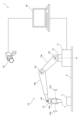
- FIG. 1 is a diagram schematically showing a usage pattern of a robot monitoring system 1 according to an embodiment.
- the robot monitoring system 1 monitors the motion of the robot arm 10.
- a robot arm 10 is installed near the belt conveyor 4 .
- the robot arm 10 transfers the article 3 loaded at a predetermined position to the container 2 on the belt conveyor 4 .
- the robot arm 10 includes a base 11 , a support 12 , arms 13 a and 13 b and a hand 14 .
- the base 11 is installed on the side of the belt conveyor 4.
- the support base 12 is installed on the base 11 so as to be rotatable about a rotation axis A1 parallel to the vertical direction.
- the arm 13a is installed on the support base 12 so as to be rotatable about a rotation axis A2 parallel to the horizontal direction.
- the arm 13b is installed at the end of the arm 13a so as to be rotatable about a rotation axis A3 parallel to the horizontal direction.
- the hand 14 is installed at the end of the arm 13b so as to be rotatable about a horizontally parallel rotating shaft A4.
- the hand 14 has a plurality of claws 14a for gripping the article 3. As shown in FIG.
- the robot arm 10 includes a plurality of drive mechanisms for rotating the support base 12, the arms 13a and 13b, and the hand 14 about the rotation axes A1 to A4.
- the robot arm 10 can three-dimensionally move the hand 14 by driving the motors that are the driving sources of these drive mechanisms.
- the hand 14 also has a driving mechanism for opening and closing the plurality of claws 14a.
- the robot arm 10 can grip and release the article 3 by driving the motor that is the drive source of the drive mechanism.
- a control command for operating the hand 14 within a predetermined operating range is set in the robot arm 10 in advance.
- the control command includes the drive amount of each drive mechanism (motor) for moving the hand 14 from the initial position to the target position and returning from the target position to the initial position. More specifically, with respect to a plurality of positions (nodes) on the movement trajectory of the hand 14, the drive amount of each drive mechanism (motor) for moving the hand 14 to the node is determined sequentially from the initial position node. is set to
- the control command includes a command for opening and closing the claw 14a of the hand 14 at the target position in addition to the control amount.
- control commands are set in the robot arm 10 by the user via the monitoring device 30, for example.
- the above control command may be set in the robot arm 10 via a terminal other than the monitoring device 30 .
- the robot monitoring system 1 includes a camera 20, a monitoring device 30, and object sensors 41a and 41b.
- the camera 20 captures at least the motion range of the robot arm 10 .
- the camera 20 is installed at a position where the robot arm 10 can be viewed from above.
- the monitoring device 30 is connected to communicate with the camera 20 and the object sensors 41a and 41b via communication lines. Communication between the monitoring device 30 and the cameras and object sensors 41a and 41b may be performed by wireless communication instead of the communication line.
- the monitoring device 30 monitors the motion of the robot arm 10 based on the image captured by the camera 20 and the detection results of the object sensors 41a and 41b. Monitoring control of the robot arm 10 will be described later with reference to FIGS. 6 and 7. FIG.
- the object sensors 41a and 41b detect that the hand 14 has reached a predetermined monitoring position set within the movement range of the hand 14.
- the monitoring position is set, for example, at the target position described above.
- the monitoring position is not limited to one position, and may be set at a plurality of positions within the operating range.
- the object sensors 41a and 41b are composed of infrared sensors.
- the infrared rays emitted from the object sensor 41a are received by the object sensor 41b.
- the infrared rays emitted from the object sensor 41a are not received by the object sensor 41b. Therefore, whether or not the hand 14 has reached the monitoring position can be detected depending on whether or not the object sensor 41b outputs a signal corresponding to the reception of infrared rays.
- FIG. 2 is a block diagram showing the configuration of the robot arm 10, camera 20 and monitoring device 30.
- the robot arm 10 includes a control section 101, an arm drive section 102, a hand drive section 103, and a communication section 104.
- the control unit 101 has a microcomputer and controls each unit according to a program held in an internal memory. The control commands described above are held in the memory within the control unit 101 .
- the control unit 101 may be configured by an FPGA (Field Programmable Gate Array) or the like.
- the arm drive unit 102 includes the above-described motor and drive mechanism for driving the arms 13a and 13b.
- the hand drive unit 103 includes the above-described motor and drive mechanism for driving the hand 14 and the claw 14a of the hand 14 .
- the communication unit 104 is a communication interface for communicating with the monitoring device 30 .
- the communication unit 104 communicates with the communication unit 305 of the monitoring device 30 under the control of the control unit 101 .
- the camera 20 includes a control unit 201, an imaging unit 202, and a communication unit 203.
- the control unit 201 is composed of, for example, a microcomputer or the like, and controls each unit according to a program stored in an internal memory.
- the imaging unit 202 includes an imaging lens and an imaging element, and performs imaging of the visual field area under the control of the control unit 201 .
- the communication unit 203 is a communication interface for communicating with the monitoring device 30 .
- the communication unit 203 communicates with the monitoring device 30 under the control of the control unit 201 .
- the monitoring device 30 includes a control unit 301 , a storage unit 302 , a display unit 303 , an input unit 304 and a communication unit 305 .
- Monitoring device 30 is configured by, for example, a general-purpose personal computer. Monitoring device 30 may be a dedicated product.
- the control unit 301 includes an arithmetic processing circuit such as a CPU (Central Processing Unit), and controls each unit according to a program stored in the storage unit 302.
- the storage unit 302 includes storage media such as ROM, RAM, and hard disk, and stores programs executed by the control unit 301 and various data. Further, the storage unit 302 is used as a work area when the control unit 301 performs control.
- the display unit 303 has a display such as a liquid crystal panel, and displays predetermined information under the control of the control unit 301 .
- the input unit 304 includes input means such as a mouse and a keyboard.
- the communication unit 305 is a communication interface for communicating with the robot arm 10, the camera 20, and the object sensors 41a and 41b. The communication unit 305 communicates with the robot arm 10, the camera 20, and the object sensors 41a and 41b under the control of the control unit 201.
- FIG. 3 is a diagram showing the configuration of a table stored in the storage unit 302 of the monitoring device 30. As shown in FIG.
- the table contains the nodes set on the movement trajectory of the hand 14, the control amount for positioning the hand 14 at each node, and the three-dimensional position of the hand 14 when the hand 14 is positioned at each node (hand position) and the required time required for the hand 14 to be positioned at each node are associated with each other.
- control amount is the amount of rotation by which the support base 12 and the arms 13a and 13b are rotated about the rotation axes A1, A2 and A3 in FIG. Specifically, the amount of rotation from the initial position of each motor that serves as a drive source for these rotations is defined as the control amount.
- each motor is a stepping motor, each number of steps from the initial position is defined as each control amount.
- the hand position is defined as a coordinate point of an orthogonal coordinate system with the installation position of the robot arm 10 as the origin.
- the X and Y axes of the Cartesian coordinate system are parallel to the horizontal plane, and the Z axis is parallel to the vertical direction.
- the origin of the orthogonal coordinate system is set, for example, at the intersection of the upper surface of the base 11 in FIG. 1 and the rotation axis A1.
- the required time is defined as the time required for the hand 14 to reach each node from the initial position during normal operation. That is, the time required for the hand 14 to reach each node from the initial position when the robot arm 10 moves without being restricted by an unexpected obstacle or the like is the required time specified for each node. It's time.
- the hand 14 sequentially moves from the first node N0 to nodes N1, N2, .
- the table defines movement positions to which the hand 14 moves sequentially and the required time to reach those positions during normal operation of the hand 14 .
- FIG. 4 is a diagram schematically showing the relationship between the field of view of the camera 20 and the orthogonal coordinate system of the robot arm 10.
- the camera 20 is installed so that the origin of the orthogonal coordinate system is included within the viewing angle ⁇ of the camera 20 . Further, the camera 20 is installed so that the motion trajectory L10 (motion range) of the hand 14 is included within the range of the viewing angle ⁇ .
- the hand 14 moves from the initial position P0 to the target position P1, and then returns from the target position P1 to the initial position P0.
- the position of the hand 14 is (x1, y1, z1).
- the control unit 301 of the monitoring device 30 Prior to the monitoring operation, the control unit 301 of the monitoring device 30 performs orthogonal A calibration process is executed to associate each coordinate point (X coordinate, Y coordinate, Z coordinate) of the coordinate system with a pixel position on the captured image of the camera 20 . That is, the light rays incident on each pixel are different for each pixel. Therefore, a coordinate point existing on a ray incident on one pixel is associated with the pixel position of the one pixel. Each pixel is associated with a plurality of coordinate points existing on the ray corresponding to the pixel.
- FIG. 5 is a flowchart showing the processing performed by the control unit 101 when the robot arm 10 actually operates.
- the control unit 101 transmits a start notification to the monitoring device 30 via the communication unit 104 (S101).
- the control unit 101 drives the arms 13a and 13b based on the control command described above to move the hand 14 to the next node (S102).
- the control unit 101 transmits the control amount for moving the hand 14 to the node after movement and the coordinate values of the orthogonal coordinate system of the node to the monitoring device via the communication unit 104. 30 (S103).
- the control unit 101 drives the claw 14a of the hand 14 in the closing direction (S105). Further, when the node after movement is at the position to release the grip (S106: YES), the control unit 101 drives the claw 14a of the hand 14 in the opening direction (S107). Then, the control unit 101 determines whether or not the processing for all nodes has been completed (S108). If the determination in step S108 is NO, the control unit 101 returns the process to step S102 to process the next node. In this way, when the processing of one step is completed (S108: YES), the control section 101 ends the processing of FIG.
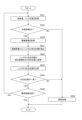
- FIG. 6 is a flowchart showing monitoring processing in the control unit 301 of the monitoring device 30.
- the control unit 301 receives the start notification transmitted in step S101 of FIG. It is determined whether or not the actual time required for the process has exceeded the standard required time defined in the table of FIG. 3 (S203). More specifically, the control unit 301 extracts the required time (reference required time) corresponding to the control amount and the hand position received in step S201 from the table in FIG. compare. Then, if the difference (time difference) between the two does not exceed a threshold that defines an allowable error (a time lag assumed to occur during normal operation), the control unit 301 determines YES in step S202. exceeds this threshold, the determination in step S202 is NO.
- step S202 determines whether the determination in step S202 is NO. If the determination in step S202 is NO, the control unit 301 assumes that some abnormality has occurred in driving the robot arm 10 and executes abnormality processing (S209). In this abnormality processing, the control unit 301, for example, causes the operation of the robot arm 10 to be urgently stopped, and causes the display unit 303 to display a screen for notifying the abnormality.
- the robot arm 10 When the robot arm 10 comes into contact with an unexpected obstacle, a certain load is applied to the robot arm 10. As a result, the robot arm 10 may move at a slower speed than during normal operation, or may be in a substantially stopped state. When the moving speed of the robot arm 10 is lower than that during normal operation, the determination result in step S202 becomes NO, and the abnormality process is executed in step S209.
- the control unit 301 of the monitoring device 30 determines NO in step S202 even when the control amount and the hand position are not received for a predetermined time or longer in step S201. More specifically, when the control unit 301 does not receive the control amount and the hand position in the next step S201 even after a predetermined period of time has passed after receiving the control amount and the hand position in the previous process of step S201, , the determination in step S202 is NO, and the abnormality processing in step S209 is executed.
- step S202 determines whether the determination in step S202 is YES.
- the control unit 301 advances the process to step S203 and executes monitoring processing based on the captured image acquired from the camera 20.
- the control unit 301 first acquires a captured image captured by the camera 20 at substantially the same timing as when the control amount and the hand position are received (S203).
- the control unit 301 receives captured images from the camera 20 at any time, and temporarily stores the received captured images in the storage unit 302 .
- step S203 the control unit 301 extracts, from the captured images temporarily stored in the storage unit 302, the captured image received at substantially the same timing as the control amount and the hand position received in step S201.
- the control unit 301 acquires the hand position Pa on the captured image corresponding to the hand position acquired in step S201, based on the association defined by the calibration process described above (S204). Also, the control unit 301 extracts the hand position Pb from the captured image acquired in step S203 (S205). In step S205, for example, the control unit 301 executes image analysis processing for extracting the outline of the area of the hand 14 from the captured image. In this case, the control unit 301 extracts the center of gravity of the extracted area as the hand position Pb. Alternatively, when the hand 14 is marked, the control unit 301 extracts the marker from the captured image and extracts the center of the extracted marker as the hand position Pb.
- a marker can be a label with a specific color such as red, for example.
- the control unit 301 After acquiring the two hand positions Pa and Pb in this way, the control unit 301 compares these two hand positions Pa and Pb (S206), and determines that these hand positions Pa and Pb are at substantially the same positions on the captured image. (S207). In step S207, the control unit 301 calculates the amount of positional deviation between these two hand positions Pa and Pb, and the calculated amount of positional deviation is the allowable error (the amount of deviation that can be assumed to occur during normal operation). Determine if it is within range. If the positional deviation amount is within this error range, the control unit 301 determines YES in step S207. If the positional deviation amount is not within this error range, the control unit 301 determines NO in step S207.
- the allowable error the amount of deviation that can be assumed to occur during normal operation
- step S207 determines whether or not the hand 14 has reached the final movement position, that is, the last node Nk shown in FIG. 3 (S208). If the hand 14 has not reached the final movement position, the control unit 301 returns the process to step S201 and receives subsequent control variables and hand positions from the robot arm 10 . After that, the control unit 301 executes the same processing (S202 to S209) as described above. Thus, when the hand 14 reaches the final movement position without executing the abnormality processing in step S209 (S208: YES), the control section 301 ends the processing of FIG.
- FIG. 7 is a flowchart showing another monitoring process in the control unit 301 of the monitoring device 30.
- FIG. 7 is a flowchart showing another monitoring process in the control unit 301 of the monitoring device 30.
- the control unit 301 continuously refers to the detection signals received from the object sensors 41a and 41b, and determines whether or not the hand 14 has reached the monitoring position within a predetermined period of time from the start of the operation of the robot arm 10 (S301). , S302).
- the predetermined time is set to the time required for the hand 14 to reach the monitoring position when the robot arm 10 operates normally.
- the control unit 301 executes the same abnormality processing as step S209 in FIG. 8 (S304).
- the control unit 301 determines whether or not the current monitoring position is the final monitoring position (S303). If the current monitoring position is not the final monitoring position (S303: NO), the control unit 301 returns the process to step S301 and executes the same process for the next monitoring position.
- the control unit 301 terminates the process of FIG.
- the control unit 301 changes the motion position of the hand 14 (monitoring target) obtained from the robot arm 10 via the communication unit 305 and the imaged image obtained from the camera 20 via the communication unit 305.
- a process of determining an operation abnormality of the robot arm 10 by comparing the operation position of the hand 14 (monitoring target) based on the robot arm 10 (S203 to S207: first determination process); is acquired with the timing based on the time information (required time) associated with the motion position in the table of FIG. processing) and
- the operation abnormality of the robot arm 10 can be determined by the process using the captured image of the robot arm 10 (S203 to S207: first determination process).
- time information (required time) regarding the timing at which the hand 14 (monitoring target) is positioned at each operation position is used.
- S202 second determination process
- the table holds, as time information, the time required for the hand 14 (monitoring target) to reach each operating position from the initial position (reference position).
- step S202 of FIG. 6 second determination processing
- the control unit 301 compares the required time up to the timing when the motion position is acquired from the robot arm 10 and the required time associated with the motion position in the table. Abnormal operation of the robot arm 10 is determined based on whether the difference exceeds a predetermined threshold. As a result, when the movement speed of the robot arm 10 decreases or the robot arm 10 becomes unable to move because the robot arm 10 comes into contact with some obstacle or the like, the determination in step S202 becomes NO, and the robot A malfunction of the arm 10 is determined. Therefore, it is possible to appropriately determine whether the robot arm 10 is malfunctioning.
- the control unit 301 detects the detection result indicating that the hand 14 (monitoring target) has reached the monitoring position within a predetermined time after the hand 14 (monitoring target) starts operating. 41b, the process of determining whether the robot arm 10 is abnormal in operation (S301, S302: third determination process) is further executed. As a result, for example, even if the monitoring device 30 cannot properly receive the operation position (hand position) from the robot arm 10 due to a communication failure or the like, the processing of FIG. can.
- the control unit 301 converts the motion position of the hand 14 (monitoring target) acquired from the robot arm 10 via the communication unit 305 into a motion position on the captured image. Then, the converted operating position is compared with the operating position of the hand 14 (monitoring target) based on the captured image to determine whether the robot arm 10 is operating abnormally. As a result, it is possible to appropriately determine whether the robot arm 10 is malfunctioning by a simple process.
- the table shown in FIG. 3 was used in the determination process (second determination process) in step S202 of FIG. determination process). For example, as shown in FIG. 8, as time information associated with each node (operation position), the timing at which the hand 14 (monitoring target) reaches one node (operation position), ) may be held.
- step S211 the control unit 301 determines the time required for the hand 14 (inspection target) to move from the hand position (operation position) corresponding to the previous node to the hand position (operation position) corresponding to the current node, That is, based on whether the time difference between the reception timing in the previous step S201 and the reception timing in the current step S201 exceeds the time difference associated with the current hand position (operation position) in the table of FIG. A malfunction of the robot arm 10 is determined.
- step S211 is performed. becomes NO, and it is determined that the robot arm 10 is abnormal in operation. Therefore, it is possible to appropriately determine whether the robot arm 10 is malfunctioning.
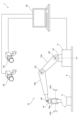
- one camera 20 is used to overlook the robot arm 10 , but two or more cameras 20 may be used to overlook the robot arm 10 .
- the distance to the hand 14 may be further obtained by performing stereo matching processing (stereo corresponding point search processing) on the captured images obtained by the plurality of cameras 20 .
- the robot monitoring system 1 further includes a camera 50 .
- calibration processing may be performed to associate the three-dimensional position acquired from the captured image with the three-dimensional position of the orthogonal coordinate system set on the robot arm 10 .
- steps S221 to S224 in FIG. 11 are performed instead of steps S204 to S207 in FIG.
- the control unit 301 uses the image captured by the camera 50 as a reference image, and executes stereo corresponding point search processing between the image captured by the camera 20 and the reference image.
- control unit 301 divides the image captured by the camera 20 into pixel blocks of a predetermined size (for example, pixel blocks of 3 vertical ⁇ 3 horizontal), and selects one of the divided pixel blocks as a pixel block to be processed.
- the control unit 301 searches the reference image for a pixel block (matching pixel block) that matches the target pixel block (the pixel value of each pixel has the highest correlation).
- the correlation is calculated by SAD (Sum of Absolute Difference), SSD (Sum of Squared Difference), or the like.
- the search range is set, for example, in the separation direction of the cameras 20 and 50 with a pixel block on the reference image located at the same position as the target pixel block as a reference position.
- the control unit 301 extracts the amount of pixel deviation between the reference position and the matching pixel block as parallax, and calculates the distance to each part of the robot arm 10 from this parallax by triangulation.
- the control unit 301 executes the above processing for all pixel blocks on the image captured by the camera 20, and generates a distance image in which each pixel block is associated with a distance.
- the control unit 301 acquires the three-dimensional position of the hand 14 (monitoring target) from the position of the hand 14 (monitoring target) on the range image.
- step S222 the control unit 301 converts the obtained three-dimensional position of the hand 14 (monitoring target) into a three-dimensional position of the robot arm 10 in the orthogonal coordinate system. That is, the control unit 301 converts the three-dimensional position including the direction and distance corresponding to the pixel position of the hand 14 into the three-dimensional position of the robot arm 10 in the orthogonal coordinate system.
- step S223 the control unit 301 compares the converted three-dimensional position with the hand position acquired from the robot arm 10 in step S201.
- step S224 the control unit 301 determines whether the converted three-dimensional position and the hand position (three-dimensional position) obtained from the robot arm 10 are substantially the same. That is, the control unit 301 determines whether or not the difference between these two three-dimensional positions exceeds a predetermined threshold (difference assumed to occur during normal operation). If the difference does not exceed the threshold (S224: YES), the control unit 301 advances the process to step S208, and if the difference exceeds the threshold (S224: NO), the control unit 301 advances the process to step S209. proceed.
- a predetermined threshold difference assumed to occur during normal operation.
- the control unit 301 converts the motion position of the monitoring target based on the captured image into the motion position in the orthogonal coordinate system of the robot arm 10, and the motion position after conversion and the communication Operational abnormality of the robot arm 10 is determined by comparing with the operation position of the hand 14 (monitoring target) obtained from the robot arm 10 via the unit 305 . By comparing the three-dimensional position of the hand 14 (monitoring target) in this way, it is possible to more appropriately determine whether the robot arm 10 is malfunctioning.
- a projection device that irradiates a pattern light having a specific pattern (intensity distribution) in the movement range of the robot arm 10 is arranged, and the robot arm 10 irradiated with the pattern light is projected onto the camera 20 .
- the distance of the hand 14 may be detected from the captured image captured in .
- the robot monitoring system 1 further includes a projection device.
- the storage unit 302 of the monitoring device 30 holds the reference image in which the patterns are distributed.
- the control unit 301 of the monitoring device 30 searches the reference image for a pixel block that has the highest correlation with the target pixel block on the captured image.
- the search range is set, for example, in the separation direction between the camera 20 and the projection device, using the same position as the target pixel block as a reference position.
- the control unit 301 detects, as parallax, the amount of pixel deviation from the reference position of the pixel block extracted by the search.
- the control unit 301 calculates the distance to the hand 14 (monitoring target) from this parallax by triangulation.
- one camera 20 captures the motion range of one robot arm 10
- one camera 20 may capture the motion ranges of a plurality of robot arms 10
- the monitoring device 30 may divide the captured image of the camera 20 into regions of each robot arm 10 and monitor the motion of each robot arm 10 .
- the monitoring control in FIG. 7 was executed in parallel with the monitoring control in FIG. 6, but the monitoring control in FIG. 7 may be omitted.
- the object sensors 41a and 41b can be omitted from the configuration of FIG.
- the robot arm 10 configured as shown in FIG. 1 was monitored by the robot monitoring system 1, but the configuration of the monitored robot arm 10 is not limited to the configuration shown in FIG.
- the number of bendable arms is not limited to two and may be other numbers.
- the configuration for holding the article 3 is not limited to the configuration in which it is held by the claws 14a, and may be a configuration in which the article is sucked under negative pressure.
- an object sensor other than an infrared sensor may be used.
- the robot monitored by the robot monitoring system 1 is not limited to the robot arm 10, and may be other types of robots.
- robot monitoring system 10 robot arm (robot) 14 hands (observed) 20 camera 30 monitoring device 301 control unit 302 storage unit 305 communication unit
Abstract
A storage unit (302) of a monitoring device (30) stores a table in which a series of operation positions along which a hand of a robot arm (10) moves, and temporal information related to timing at which the hand is positioned in each of the of operation positions are associated with each other. A control unit (301) executes: first determination processing of determining operational anomaly of the robot arm (10) through comparison between the operation position of the hand acquired from the robot arm (10) and the operation position of the hand based on a captured image acquired from a camera (20); and second determination processing of determining operational anomaly of the robot arm (10) through comparison between timing of acquisition of the operation position from the robot arm (10) and timing based on the temporal information associated with the operation position in the table.
Description
本発明は、ロボットの動作を監視するロボット監視システム、ロボットの動作を監視する監視装置、当該監視装置の制御方法および当該監視装置に所定の機能を実行させるプログラムに関する。
The present invention relates to a robot monitoring system that monitors the motion of a robot, a monitoring device that monitors the motion of a robot, a control method for the monitoring device, and a program that causes the monitoring device to perform a predetermined function.
従来、ファクトリーオートメーション等の分野においてロボットが利用されている。たとえば、ベルトコンベア付近にロボットアームが設置される。ロボットアームは、予め設定された制御コマンドにより、たとえば、所定の位置に積載されている物品をベルトコンベア上のコンテナに移し替える。
Conventionally, robots have been used in fields such as factory automation. For example, a robot arm is installed near the belt conveyor. The robot arm transfers, for example, an article loaded at a predetermined position to a container on a belt conveyor according to a preset control command.
以下の特許文献1には、ロボットの動作中にロボットに異常が生じたことを検知する方法が記載されている。この方法では、ロボットの動作範囲を俯瞰するカメラが設置される。カメラにより取得された画像と、カメラ方角から見たロボット位置のシミュレーション画像とが比較される。これら2つの画像に所定量を超える差異がある場合に、ロボットの動作に異常が生じたと判定される。
Patent Document 1 below describes a method for detecting that an abnormality has occurred in a robot during its operation. In this method, a camera is installed to overlook the motion range of the robot. An image acquired by the camera is compared with a simulated image of the robot position as seen from the camera direction. If the two images differ by more than a predetermined amount, it is determined that an anomaly has occurred in the robot's motion.
しかしながら、上記の方法では、カメラの撮像方向において、たとえば、ロボットのハンドがアームの背後に隠れる、いわゆるオクルージョンが生じることがある。このようなオクルージョンは、特に、複数のロボットを1つのカメラで撮像する場合等、カメラの設置位置が一定の制限を受ける場合に起こりやすい。このようなオクルージョンが生じると、カメラの画像にハンドが写らなくなるため、カメラの画像とシミュレーション画像とを比較したとしても、ハンドの動作異常を適正に判定することができない。
However, in the above method, so-called occlusion may occur in the imaging direction of the camera, for example, the robot's hand is hidden behind the arm. Such occlusion is particularly likely to occur when the installation positions of the cameras are subject to certain restrictions, such as when imaging a plurality of robots with one camera. When such an occlusion occurs, the hand is not captured in the camera image, so even if the camera image and the simulation image are compared, it is not possible to properly determine whether the hand is malfunctioning.
かかる課題に鑑み、本発明は、ロボットの撮像画像において監視対象にオクルージョンが生じても、ロボットの動作異常を適正かつ正確に判定することが可能なロボット監視システム、監視装置、監視装置の制御方法およびプログラムを提供することを目的とする。
In view of such problems, the present invention provides a robot monitoring system, a monitoring device, and a control method for a monitoring device that can appropriately and accurately determine an abnormal operation of a robot even if occlusion occurs in the monitored object in the captured image of the robot. and to provide programs.
本発明の第1の態様は、ロボット監視システムに関する。この態様に係るロボット監視システムは、少なくともロボットの動作範囲を撮像するカメラと、前記カメラの撮像画像に基づいて前記ロボットの動作を監視する監視装置と、を備える。前記監視装置は、記憶部と、制御部と、前記ロボットおよび前記カメラと通信を行う通信部と、を備える。前記記憶部は、前記ロボットの監視対象が移動する一連の動作位置と、各々の前記動作位置に前記監視対象が位置づけられるタイミングに関する時間情報とを互いに対応付けたテーブルを記憶する。前記制御部は、前記通信部を介して前記ロボットから取得した前記監視対象の動作位置と、前記通信部を介して前記カメラから取得した前記撮像画像に基づく前記監視対象の動作位置とを比較して、前記ロボットの動作異常を判定する第1判定処理と、前記通信部を介して前記ロボットから前記動作位置を取得したタイミングと、前記テーブルにおいて当該動作位置に対応付けられた前記時間情報に基づくタイミングとを比較して、前記ロボットの動作異常を判定する第2判定処理と、を実行する。
A first aspect of the present invention relates to a robot monitoring system. A robot monitoring system according to this aspect includes at least a camera that captures an action range of a robot, and a monitoring device that monitors the action of the robot based on an image captured by the camera. The monitoring device includes a storage unit, a control unit, and a communication unit that communicates with the robot and the camera. The storage unit stores a table in which a series of motion positions to which the monitoring target of the robot moves and time information regarding the timing at which the monitoring target is positioned at each motion position are associated with each other. The control unit compares the motion position of the monitored object obtained from the robot via the communication unit with the motion position of the monitored object based on the captured image obtained from the camera via the communication unit. based on a first determination process for determining an operation abnormality of the robot, the timing at which the operation position is acquired from the robot via the communication unit, and the time information associated with the operation position in the table. and a second determination process of comparing with the timing and determining an operation abnormality of the robot.
本態様に係るロボット監視システムによれば、ロボットの撮像画像を用いた第1判定処理により、ロボットの動作異常を判定できる。また、この撮像画像において、ロボットの監視対象にオクルージョンが生じたとしても、各々の動作位置に監視対象が位置づけられるタイミングに関する時間情報を用いた第2判定処理により、ロボットの動作異常を判定できる。よって、ロボットの動作異常を適正かつ確実に判定することができる。
According to the robot monitoring system according to this aspect, it is possible to determine whether the robot is malfunctioning by the first determination process using the captured image of the robot. In addition, even if occlusion occurs in the monitored object of the robot in this captured image, it is possible to determine abnormal motion of the robot by the second determination processing using the time information regarding the timing at which the monitored object is positioned at each motion position. Therefore, it is possible to properly and reliably determine whether the robot is malfunctioning.
本発明の第2の態様は、ロボットの動作を監視する監視装置に関する。この態様に係る監視装置は、記憶部と、制御部と、前記ロボットおよび少なくともロボットの動作範囲を撮像するカメラと通信を行う通信部と、を備える。前記記憶部は、前記ロボットの監視対象が移動する一連の動作位置と、各々の前記動作位置に前記監視対象が位置づけられるタイミングに関する時間情報とを互いに対応付けたテーブルを記憶する。前記制御部は、前記通信部を介して前記ロボットから取得した前記監視対象の動作位置と、前記通信部を介して前記カメラから取得した前記撮像画像に基づく前記監視対象の動作位置とを比較して、前記ロボットの動作異常を判定する第1判定処理と、前記通信部を介して前記ロボットから前記動作位置を取得したタイミングと、前記テーブルにおいて当該動作位置に対応付けられた前記時間情報に基づくタイミングとを比較して、前記ロボットの動作異常を判定する第2判定処理と、を実行する。
A second aspect of the present invention relates to a monitoring device that monitors the motion of a robot. A monitoring device according to this aspect includes a storage unit, a control unit, and a communication unit that communicates with the robot and at least a camera that captures an action range of the robot. The storage unit stores a table in which a series of motion positions to which the monitoring target of the robot moves and time information regarding the timing at which the monitoring target is positioned at each motion position are associated with each other. The control unit compares the motion position of the monitored object obtained from the robot via the communication unit with the motion position of the monitored object based on the captured image obtained from the camera via the communication unit. based on a first determination process for determining an operation abnormality of the robot, the timing at which the operation position is acquired from the robot via the communication unit, and the time information associated with the operation position in the table. and a second determination process of comparing with the timing and determining an operation abnormality of the robot.
本発明の第3の態様は、ロボットの動作を監視する監視装置の制御方法に関する。この態様に係る監視装置の制御方法において、前記監視装置は、前記ロボットの監視対象が移動する一連の動作位置と、各々の前記動作位置に前記監視対象が位置づけられるタイミングに関する時間情報とを互いに対応付けたテーブルを記憶する。監視装置の制御方法は、通信部を介して前記ロボットから前記監視対象の動作位置を取得する工程と、少なくともロボットの動作範囲を撮像するカメラから前記通信部を介して撮像画像を取得する工程と、前記ロボットから取得した前記監視対象の動作位置と、前記カメラからから取得した前記撮像画像に基づく前記監視対象の動作位置とを比較して、前記ロボットの動作異常を判定する工程と、前記ロボットから前記動作位置を取得したタイミングと、前記テーブルにおいて当該動作位置に対応付けられた前記時間情報に基づくタイミングとを比較して、前記ロボットの動作異常を判定する工程と、を含む。
A third aspect of the present invention relates to a control method for a monitoring device that monitors the motion of a robot. In the monitoring device control method according to this aspect, the monitoring device associates a series of motion positions to which the monitored object of the robot moves with time information regarding the timing at which the monitored target is positioned at each of the motion positions. Remember the attached table. A method for controlling a monitoring device includes the steps of: obtaining an operation position of the object to be monitored from the robot via a communication unit; and obtaining a captured image from a camera that captures at least an operation range of the robot via the communication unit. a step of comparing an operating position of the monitored object obtained from the robot with an operating position of the monitored object based on the captured image obtained from the camera to determine an abnormal operation of the robot; comparing the timing at which the motion position is acquired from the table with the timing based on the time information associated with the motion position in the table, and determining an operation abnormality of the robot.
本発明の第4の態様は、ロボットの動作を監視する監視装置の制御部に所定の機能を実行させるプログラムに関する。この態様に係るプログラムは、前記ロボットの監視対象が移動する一連の動作位置と、各々の前記動作位置に前記監視対象が位置づけられるタイミングに関する時間情報とを互いに対応付けたテーブルを含む。プログラムは、通信部を介して前記ロボットから前記監視対象の動作位置を取得する機能と、少なくともロボットの動作範囲を撮像するカメラから前記通信部を介して撮像画像を取得する機能と、前記ロボットから取得した前記監視対象の動作位置と、前記カメラから取得した前記撮像画像に基づく前記監視対象の動作位置とを比較して、前記ロボットの動作異常を判定する機能と、前記ロボットから前記動作位置を取得したタイミングと、前記テーブルにおいて当該動作位置に対応付けられた前記時間情報に基づくタイミングとを比較して、前記ロボットの動作異常を判定する機能と、を前記制御部に実行させる。
A fourth aspect of the present invention relates to a program that causes a control unit of a monitoring device that monitors the motion of a robot to execute a predetermined function. The program according to this aspect includes a table in which a series of motion positions to which the monitored target of the robot moves and time information regarding the timing at which the monitored target is positioned at each of the motion positions are associated with each other. The program has a function of acquiring the operating position of the monitoring target from the robot via the communication unit, a function of acquiring a captured image from a camera that captures at least the operating range of the robot through the communication unit, and a function of acquiring a captured image from the robot through the communication unit. a function of determining an operation abnormality of the robot by comparing the acquired motion position of the monitored target with the motion position of the monitored target based on the captured image acquired from the camera; The control unit is caused to perform a function of comparing the acquired timing with the timing based on the time information associated with the motion position in the table, and determining an operation abnormality of the robot.
上記第2ないし第4の態様によれば、上記第1の態様と同様の効果が奏され得る。
According to the second to fourth aspects, the same effect as the first aspect can be achieved.
以上のとおり、本発明によれば、ロボットの撮像画像において監視対象にオクルージョンが生じても、ロボットの動作異常を適正かつ正確に判定することが可能なロボット監視システム、監視装置、監視装置の制御方法およびプログラムを提供できる。
As described above, according to the present invention, the robot monitoring system, the monitoring device, and the control of the monitoring device are capable of appropriately and accurately judging an abnormal operation of the robot even if occlusion occurs in the monitored object in the captured image of the robot. Can provide methods and programs.
本発明の効果ないし意義は、以下に示す実施形態の説明により、さらに明らかとなろう。ただし、以下に示す実施形態は、あくまでも、本発明を実施化する際の一つの例示であって、本発明は、以下の実施形態に記載されたものに何ら制限されるものではない。
The effects and significance of the present invention will become clearer from the description of the embodiments shown below. However, the embodiment shown below is merely one example of the implementation of the present invention, and the present invention is not limited to the embodiments described below.
ただし、図面はもっぱら説明のためのものであって、この発明の範囲を限定するものではない。
However, the drawings are for illustration only and do not limit the scope of the present invention.
以下、本発明の実施形態について、図面を参照して説明する。
Hereinafter, embodiments of the present invention will be described with reference to the drawings.
図1は、実施形態に係る、ロボット監視システム1の使用形態を模式的に示す図である。
FIG. 1 is a diagram schematically showing a usage pattern of a robot monitoring system 1 according to an embodiment.
ロボット監視システム1は、ロボットアーム10の動作を監視する。ベルトコンベア4付近にロボットアーム10が設置されている。ロボットアーム10は、所定の位置に積載されている物品3をベルトコンベア4上のコンテナ2に移し替える。ロボットアーム10は、ベース11と、支持台12と、アーム13a、13bと、ハンド14を備える。
The robot monitoring system 1 monitors the motion of the robot arm 10. A robot arm 10 is installed near the belt conveyor 4 . The robot arm 10 transfers the article 3 loaded at a predetermined position to the container 2 on the belt conveyor 4 . The robot arm 10 includes a base 11 , a support 12 , arms 13 a and 13 b and a hand 14 .
ベース11は、ベルトコンベア4の側方に設置される。支持台12は、鉛直方向に平行な回動軸A1について回動可能にベース11に設置される。アーム13aは、水平方向に平行な回動軸A2について回動可能に支持台12に設置される。アーム13bは、水平方向に平行な回動軸A3について回動可能にアーム13aの端部に設置される。ハンド14は、水平方向に平行な回動軸A4について回動可能にアーム13bの端部に設置される。ハンド14は、物品3を把持するための複数の爪14aを有している。
The base 11 is installed on the side of the belt conveyor 4. The support base 12 is installed on the base 11 so as to be rotatable about a rotation axis A1 parallel to the vertical direction. The arm 13a is installed on the support base 12 so as to be rotatable about a rotation axis A2 parallel to the horizontal direction. The arm 13b is installed at the end of the arm 13a so as to be rotatable about a rotation axis A3 parallel to the horizontal direction. The hand 14 is installed at the end of the arm 13b so as to be rotatable about a horizontally parallel rotating shaft A4. The hand 14 has a plurality of claws 14a for gripping the article 3. As shown in FIG.
ロボットアーム10は、回動軸A1~A4について支持台12、アーム13a、13bおよびハンド14をそれぞれ回動させる複数の駆動機構を備えている。ロボットアーム10は、これら駆動機構の駆動源であるモータを駆動することにより、ハンド14を3次元に移動させ得る。また、ハンド14は、複数の爪14aを開閉するための駆動機構を備えている。ロボットアーム10は、この駆動機構の駆動源であるモータを駆動することにより、物品3の把持および把持の解除を行い得る。
The robot arm 10 includes a plurality of drive mechanisms for rotating the support base 12, the arms 13a and 13b, and the hand 14 about the rotation axes A1 to A4. The robot arm 10 can three-dimensionally move the hand 14 by driving the motors that are the driving sources of these drive mechanisms. The hand 14 also has a driving mechanism for opening and closing the plurality of claws 14a. The robot arm 10 can grip and release the article 3 by driving the motor that is the drive source of the drive mechanism.
ロボットアーム10には、予め、ハンド14を所定の動作範囲で動作させるための制御コマンドが設定される。制御コマンドは、ハンド14を初期位置から目標位置へと移動させ、さらに、目標位置から初期位置へと復帰させるための、各駆動機構(モータ)の駆動量を含む。より詳細には、ハンド14の移動軌跡上の複数の位置(ノード)について、初期位置のノードから順に、そのノードにハンド14を移動させるための各駆動機構(モータ)の駆動量が、そのノードに設定される。制御コマンドは、上記制御量の他、上記目標位置においてハンド14の爪14aを開閉させるためのコマンドを含んでいる。
A control command for operating the hand 14 within a predetermined operating range is set in the robot arm 10 in advance. The control command includes the drive amount of each drive mechanism (motor) for moving the hand 14 from the initial position to the target position and returning from the target position to the initial position. More specifically, with respect to a plurality of positions (nodes) on the movement trajectory of the hand 14, the drive amount of each drive mechanism (motor) for moving the hand 14 to the node is determined sequentially from the initial position node. is set to The control command includes a command for opening and closing the claw 14a of the hand 14 at the target position in addition to the control amount.
このような制御コマンドは、たとえば、監視装置30を介して、ユーザがロボットアーム10に設定する。あるいは、監視装置30以外の端末を介して、上記制御コマンドがロボットアーム10に設定されてもよい。
Such control commands are set in the robot arm 10 by the user via the monitoring device 30, for example. Alternatively, the above control command may be set in the robot arm 10 via a terminal other than the monitoring device 30 .
ロボット監視システム1は、カメラ20と、監視装置30と、物体センサ41a、41bとを備える。
The robot monitoring system 1 includes a camera 20, a monitoring device 30, and object sensors 41a and 41b.
カメラ20は、少なくとも、ロボットアーム10の動作範囲を撮像する。カメラ20は、ロボットアーム10を俯瞰可能な位置に設置される。
The camera 20 captures at least the motion range of the robot arm 10 . The camera 20 is installed at a position where the robot arm 10 can be viewed from above.
監視装置30は、通信線により、カメラ20および物体センサ41a、41bと通信に接続されている。通信線に代えて、無線通信により、監視装置30とカメラおよび物体センサ41a、41bとの通信が行われてもよい。監視装置30は、カメラ20の撮像画像および物体センサ41a、41bの検知結果に基づいて、ロボットアーム10の動作を監視する。ロボットアーム10の監視制御については、追って、図6および図7を参照して説明する。
The monitoring device 30 is connected to communicate with the camera 20 and the object sensors 41a and 41b via communication lines. Communication between the monitoring device 30 and the cameras and object sensors 41a and 41b may be performed by wireless communication instead of the communication line. The monitoring device 30 monitors the motion of the robot arm 10 based on the image captured by the camera 20 and the detection results of the object sensors 41a and 41b. Monitoring control of the robot arm 10 will be described later with reference to FIGS. 6 and 7. FIG.
物体センサ41a、41bは、ハンド14の動作範囲内に設定された所定の監視位置に、ハンド14が到達したことを検知する。監視位置は、たとえば、上述の目標位置に設定される。監視位置は、1カ所に限らず、動作範囲内に複数個所、設定されてもよい。
The object sensors 41a and 41b detect that the hand 14 has reached a predetermined monitoring position set within the movement range of the hand 14. The monitoring position is set, for example, at the target position described above. The monitoring position is not limited to one position, and may be set at a plurality of positions within the operating range.
本実施形態では、物体センサ41a、41bが、赤外線センサで構成される。物体センサ41a、41bの間にハンド14が存在しない場合、物体センサ41aから出射された赤外線は、物体センサ41bで受光される。物体センサ41a、41bの間にハンド14が存在する場合、物体センサ41aから出射された赤外線は、物体センサ41bで受光されない。したがって、物体センサ41bから赤外線の受光に応じた信号が出力されるか否かによって、ハンド14が監視位置に到達したか否かが検知され得る。
In this embodiment, the object sensors 41a and 41b are composed of infrared sensors. When the hand 14 does not exist between the object sensors 41a and 41b, the infrared rays emitted from the object sensor 41a are received by the object sensor 41b. When the hand 14 exists between the object sensors 41a and 41b, the infrared rays emitted from the object sensor 41a are not received by the object sensor 41b. Therefore, whether or not the hand 14 has reached the monitoring position can be detected depending on whether or not the object sensor 41b outputs a signal corresponding to the reception of infrared rays.
図2は、ロボットアーム10、カメラ20および監視装置30の構成を示すブロック図である。
FIG. 2 is a block diagram showing the configuration of the robot arm 10, camera 20 and monitoring device 30.
ロボットアーム10は、制御部101と、アーム駆動部102と、ハンド駆動部103と、通信部104とを備える。
The robot arm 10 includes a control section 101, an arm drive section 102, a hand drive section 103, and a communication section 104.
制御部101は、マイクロコンピュータを備え、内蔵メモリに保持されたプログラムに従って各部を制御する。上述の制御コマンドは、制御部101内のメモリに保持される。制御部101が、FPGA(Field Programmable Gate Array)等により構成されてもよい。
The control unit 101 has a microcomputer and controls each unit according to a program held in an internal memory. The control commands described above are held in the memory within the control unit 101 . The control unit 101 may be configured by an FPGA (Field Programmable Gate Array) or the like.
アーム駆動部102は、アーム13a、13bを駆動するための上述のモータおよび駆動機構を備える。ハンド駆動部103は、ハンド14およびハンド14の爪14aを駆動するための上述のモータおよび駆動機構を備える。通信部104は、監視装置30と通信を行うための通信インタフェースである。通信部104は、制御部101からの制御により、監視装置30の通信部305と通信を行う。
The arm drive unit 102 includes the above-described motor and drive mechanism for driving the arms 13a and 13b. The hand drive unit 103 includes the above-described motor and drive mechanism for driving the hand 14 and the claw 14a of the hand 14 . The communication unit 104 is a communication interface for communicating with the monitoring device 30 . The communication unit 104 communicates with the communication unit 305 of the monitoring device 30 under the control of the control unit 101 .
カメラ20は、制御部201と、撮像部202と、通信部203とを備える。制御部201は、たとえば、マイクロコンピュータ等により構成され、内蔵メモリに記憶されたプログラムに従って各部を制御する。撮像部202は、撮像レンズと撮像素子とを備え、制御部201からの制御により視野領域に対する撮像を行う。通信部203は、監視装置30と通信を行うための通信インタフェースである。通信部203は、制御部201からの制御により、監視装置30と通信を行う。
The camera 20 includes a control unit 201, an imaging unit 202, and a communication unit 203. The control unit 201 is composed of, for example, a microcomputer or the like, and controls each unit according to a program stored in an internal memory. The imaging unit 202 includes an imaging lens and an imaging element, and performs imaging of the visual field area under the control of the control unit 201 . The communication unit 203 is a communication interface for communicating with the monitoring device 30 . The communication unit 203 communicates with the monitoring device 30 under the control of the control unit 201 .
監視装置30は、制御部301と、記憶部302と、表示部303と、入力部304と、通信部305とを備える。監視装置30は、たとえば、汎用のパーソナルコンピューターにより構成される。監視装置30が専用品であってもよい。
The monitoring device 30 includes a control unit 301 , a storage unit 302 , a display unit 303 , an input unit 304 and a communication unit 305 . Monitoring device 30 is configured by, for example, a general-purpose personal computer. Monitoring device 30 may be a dedicated product.
制御部301は、CPU(Central Processing Unit)等の演算処理回路を備え、記憶部302に記憶されたプログラムに従って各部を制御する。記憶部302は、ROM、RAM、ハードディスク等の記憶媒体を備え、制御部301が実行するプログラムや、各種データを記憶する。また、記憶部302は、制御部301が制御を行う際のワーク領域として利用される。
The control unit 301 includes an arithmetic processing circuit such as a CPU (Central Processing Unit), and controls each unit according to a program stored in the storage unit 302. The storage unit 302 includes storage media such as ROM, RAM, and hard disk, and stores programs executed by the control unit 301 and various data. Further, the storage unit 302 is used as a work area when the control unit 301 performs control.
表示部303は、液晶パネル等のディスプレイを備え、制御部301からの制御により、所定の情報を表示する。入力部304は、マウスやキーボード等の入力手段を備える。通信部305は、ロボットアーム10、カメラ20および物体センサ41a、41bと通信を行うための通信インタフェースである。通信部305は、制御部201からの制御により、ロボットアーム10、カメラ20および物体センサ41a、41bと通信を行う。
The display unit 303 has a display such as a liquid crystal panel, and displays predetermined information under the control of the control unit 301 . The input unit 304 includes input means such as a mouse and a keyboard. The communication unit 305 is a communication interface for communicating with the robot arm 10, the camera 20, and the object sensors 41a and 41b. The communication unit 305 communicates with the robot arm 10, the camera 20, and the object sensors 41a and 41b under the control of the control unit 201. FIG.
図3は、監視装置30の記憶部302に記憶されたテーブルの構成を示す図である。
FIG. 3 is a diagram showing the configuration of a table stored in the storage unit 302 of the monitoring device 30. As shown in FIG.
テーブルには、ハンド14の移動軌跡上に設定された上記ノードと、各ノードにハンド14を位置付けるための制御量と、各ノードにハンド14を位置付けられたときのハンド14の3次元位置(ハンド位置)と、各ノードにハンド14が位置付けられるのに要する所要時間とが、互いに対応付けられている。
The table contains the nodes set on the movement trajectory of the hand 14, the control amount for positioning the hand 14 at each node, and the three-dimensional position of the hand 14 when the hand 14 is positioned at each node (hand position) and the required time required for the hand 14 to be positioned at each node are associated with each other.
ここで、制御量は、図1の回動軸A1、A2、A3について支持台12およびアーム13a、13bをそれぞれ回動させる回動量である。具体的には、これら回動の駆動源となる各モータの初期位置からの回動量が、制御量として規定される。各モータがステッピングモータである場合、初期位置からの各ステップ数が、各制御量として規定される。
Here, the control amount is the amount of rotation by which the support base 12 and the arms 13a and 13b are rotated about the rotation axes A1, A2 and A3 in FIG. Specifically, the amount of rotation from the initial position of each motor that serves as a drive source for these rotations is defined as the control amount. When each motor is a stepping motor, each number of steps from the initial position is defined as each control amount.
ハンド位置は、ロボットアーム10の設置位置を原点とする直交座標系の座標点として規定される。直交座標系のX軸およびY軸は水平面に平行であり、Z軸は鉛直方向に平行である。直交座標系の原点は、たとえば、図1のベース11の上面と回動軸A1とが交差する位置に設定される。
The hand position is defined as a coordinate point of an orthogonal coordinate system with the installation position of the robot arm 10 as the origin. The X and Y axes of the Cartesian coordinate system are parallel to the horizontal plane, and the Z axis is parallel to the vertical direction. The origin of the orthogonal coordinate system is set, for example, at the intersection of the upper surface of the base 11 in FIG. 1 and the rotation axis A1.
所要時間は、通常動作時に、ハンド14が初期位置から各ノードへと到達するのに要する時間として規定される。すなわち、ロボットアーム10が予期せぬ障害物等によって動作を制限されることなく移動したときに、ハンド14が初期位置から各ノードへと到達するのに要する時間が、各ノードに規定される所要時間である。
The required time is defined as the time required for the hand 14 to reach each node from the initial position during normal operation. That is, the time required for the hand 14 to reach each node from the initial position when the robot arm 10 moves without being restricted by an unexpected obstacle or the like is the required time specified for each node. It's time.
通常動作時において、ハンド14は、上述の制御コマンドにより、最初のノードN0からノードN1、N2…Nkへと順番に移動する。テーブルには、ハンド14の通常動作時において、ハンド14が順次移動する移動位置とその位置までの所要時間が規定されている。
During normal operation, the hand 14 sequentially moves from the first node N0 to nodes N1, N2, . The table defines movement positions to which the hand 14 moves sequentially and the required time to reach those positions during normal operation of the hand 14 .
図4は、カメラ20の視野と、ロボットアーム10の直交座標系との関係を模式的に示す図である。
FIG. 4 is a diagram schematically showing the relationship between the field of view of the camera 20 and the orthogonal coordinate system of the robot arm 10. FIG.
図4に示すように、カメラ20の視野角θの範囲内に直交座標系の原点が含まれるように、カメラ20が設置される。また、この視野角θの範囲内に、ハンド14の動作軌跡L10(動作範囲)が含まれるように、カメラ20が設置される。ハンド14は、初期位置P0から目標位置P1へと移動し、さらに、目標位置P1から初期位置P0に戻る。図4では、ハンド14の位置は、(x1,y1,z1)である。
As shown in FIG. 4, the camera 20 is installed so that the origin of the orthogonal coordinate system is included within the viewing angle θ of the camera 20 . Further, the camera 20 is installed so that the motion trajectory L10 (motion range) of the hand 14 is included within the range of the viewing angle θ. The hand 14 moves from the initial position P0 to the target position P1, and then returns from the target position P1 to the initial position P0. In FIG. 4, the position of the hand 14 is (x1, y1, z1).
監視動作に先立って、監視装置30の制御部301は、カメラ20の設置位置と、カメラ20の撮像方向(光軸の向き)および視野角と、直交座標系の原点位置とに基づいて、直交座標系の各座標点(X座標、Y座標、Z座標)を、カメラ20の撮像画像上の画素位置に対応付けるためのキャリブレーション処理を実行する。すなわち、各画素に入射する光線は、画素ごとに異なる。したがって、一の画素に入射する光線上に存在する座標点は、当該一の画素の画素位置に対応付けられる。各画素には、当該画素に対応する光線上に存在する複数の座標点が対応付けられる。
Prior to the monitoring operation, the control unit 301 of the monitoring device 30 performs orthogonal A calibration process is executed to associate each coordinate point (X coordinate, Y coordinate, Z coordinate) of the coordinate system with a pixel position on the captured image of the camera 20 . That is, the light rays incident on each pixel are different for each pixel. Therefore, a coordinate point existing on a ray incident on one pixel is associated with the pixel position of the one pixel. Each pixel is associated with a plurality of coordinate points existing on the ray corresponding to the pixel.
図5は、ロボットアーム10の実動作時に制御部101により行われる処理を示すフローチャートである。
FIG. 5 is a flowchart showing the processing performed by the control unit 101 when the robot arm 10 actually operates.
実動作が開始すると、まず、制御部101は、通信部104を介して、開始通知を監視装置30に送信する(S101)。次に、制御部101は、上述の制御コマンドに基づきアーム13a、13bを駆動して、ハンド14を次のノードに移動させる(S102)。ハンド14の移動が完了すると、制御部101は、移動後のノードにハンド14を移動させるための上記制御量と、当該ノードの直交座標系の座標値とを、通信部104を介して監視装置30に送信する(S103)。
When the actual operation starts, first, the control unit 101 transmits a start notification to the monitoring device 30 via the communication unit 104 (S101). Next, the control unit 101 drives the arms 13a and 13b based on the control command described above to move the hand 14 to the next node (S102). When the movement of the hand 14 is completed, the control unit 101 transmits the control amount for moving the hand 14 to the node after movement and the coordinate values of the orthogonal coordinate system of the node to the monitoring device via the communication unit 104. 30 (S103).
制御部101は、移動後のノードが把持位置である場合(S104:YES)、ハンド14の爪14aを閉じる方向に駆動する(S105)。また、制御部101は、移動後のノードが把持を開放する位置である場合(S106:YES)、ハンド14の爪14aを開く方向に駆動する(S107)。そして、制御部101は、全てノードに対する処理が終了したか否かを判定する(S108)。ステップS108の判定がNOの場合、制御部101は、処理をステップS102に戻して、次のノードに対する処理を行う。こうして、1工程の処理が終了すると(S108:YES)、制御部101は、図5の処理を終了する。
When the node after movement is at the grasping position (S104: YES), the control unit 101 drives the claw 14a of the hand 14 in the closing direction (S105). Further, when the node after movement is at the position to release the grip (S106: YES), the control unit 101 drives the claw 14a of the hand 14 in the opening direction (S107). Then, the control unit 101 determines whether or not the processing for all nodes has been completed (S108). If the determination in step S108 is NO, the control unit 101 returns the process to step S102 to process the next node. In this way, when the processing of one step is completed (S108: YES), the control section 101 ends the processing of FIG.
図6は、監視装置30の制御部301における監視処理を示すフローチャートである。
FIG. 6 is a flowchart showing monitoring processing in the control unit 301 of the monitoring device 30. FIG.
制御部301は、図5のステップS103により送信された制御量およびハンド位置を受信すると(S201)、図5のステップS101において送信された開始通知を受信してから、これらの情報を受信するまでに要した実際の所要時間が、図3のテーブルに規定された基準の所要時間を超過したか否かを判定する(S203)。より詳細には、制御部301は、ステップS201で受信した制御量およびハンド位置に対応する所要時間(基準の所要時間)を図3のテーブルから抽出し、抽出した所要時間と実際の所要時間とを比較する。そして、制御部301は、両者の差分(時間差)が、許容される誤差(通常動作時に生じ得ると想定される時間ずれ)を規定する閾値を超えていなければステップS202の判定をYESとし、両者の時間差がこの閾値を超えていればステップS202の判定をNOとする。
When the control unit 301 receives the control amount and the hand position transmitted in step S103 of FIG. 5 (S201), the control unit 301 receives the start notification transmitted in step S101 of FIG. It is determined whether or not the actual time required for the process has exceeded the standard required time defined in the table of FIG. 3 (S203). More specifically, the control unit 301 extracts the required time (reference required time) corresponding to the control amount and the hand position received in step S201 from the table in FIG. compare. Then, if the difference (time difference) between the two does not exceed a threshold that defines an allowable error (a time lag assumed to occur during normal operation), the control unit 301 determines YES in step S202. exceeds this threshold, the determination in step S202 is NO.
ステップS202の判定がNOの場合、制御部301は、ロボットアーム10の駆動に何らかの異常が生じたとして、異常処理を実行する(S209)。この異常処理において、制御部301は、たとえば、ロボットアーム10の動作を緊急停止させ、異常を報知するための画面を表示部303に表示させる。
If the determination in step S202 is NO, the control unit 301 assumes that some abnormality has occurred in driving the robot arm 10 and executes abnormality processing (S209). In this abnormality processing, the control unit 301, for example, causes the operation of the robot arm 10 to be urgently stopped, and causes the display unit 303 to display a screen for notifying the abnormality.
ロボットアーム10が予期せぬ障害物に接触した場合、ロボットアーム10に一定の負荷が掛かる。これにより、ロボットアーム10は、移動速度が通常動作時よりも低下し、あるいは、略停止した状態となり得る。ロボットアーム10の移動速度が通常動作時より低下した場合、ステップS202の判定結果がNOとなり、ステップS209による異常処理が実行される。
When the robot arm 10 comes into contact with an unexpected obstacle, a certain load is applied to the robot arm 10. As a result, the robot arm 10 may move at a slower speed than during normal operation, or may be in a substantially stopped state. When the moving speed of the robot arm 10 is lower than that during normal operation, the determination result in step S202 becomes NO, and the abnormality process is executed in step S209.
他方、上記障害物との接触によりロボットアーム10が略停止した状態となった場合、ロボットアーム10は、次のノードへの移動を完了しないため、制御量およびハンド位置を監視装置30に送信し得ない。したがって、監視装置30の制御部301は、ステップS201において制御量およびハンド位置を所定時間以上に亘って受信しない場合も、ステップS202の判定をNOとする。より詳細には、制御部301は、前回のステップS201の処理により制御量およびハンド位置を受信した後、所定時間が経過しても、次のステップS201による制御量およびハンド位置を受信しない場合に、ステップS202の判定をNOとして、ステップS209による異常処理を実行する。
On the other hand, when the robot arm 10 comes to a substantially stopped state due to contact with the obstacle, the robot arm 10 does not complete the movement to the next node, so the control amount and the hand position are transmitted to the monitoring device 30. I don't get it. Therefore, the control unit 301 of the monitoring device 30 determines NO in step S202 even when the control amount and the hand position are not received for a predetermined time or longer in step S201. More specifically, when the control unit 301 does not receive the control amount and the hand position in the next step S201 even after a predetermined period of time has passed after receiving the control amount and the hand position in the previous process of step S201, , the determination in step S202 is NO, and the abnormality processing in step S209 is executed.
ステップS202の判定がYESの場合、制御部301は、処理をステップS203に進めて、カメラ20から取得した撮像画像に基づく監視処理を実行する。この監視処理において、制御部301は、まず、制御量およびハンド位置を受信したタイミングと略同じタイミングでカメラ20が撮像した撮像画像を取得する(S203)。ここで、制御部301は、カメラ20から随時、撮像画像を受信しており、受信した撮像画像を記憶部302に一時記憶させている。ステップS203において、制御部301は、記憶部302に一時記憶させた撮像画像のうち、ステップS201において制御量およびハンド位置を受信したタイミングと略同じタイミングで受信した撮像画像を抽出する。
If the determination in step S202 is YES, the control unit 301 advances the process to step S203 and executes monitoring processing based on the captured image acquired from the camera 20. In this monitoring process, the control unit 301 first acquires a captured image captured by the camera 20 at substantially the same timing as when the control amount and the hand position are received (S203). Here, the control unit 301 receives captured images from the camera 20 at any time, and temporarily stores the received captured images in the storage unit 302 . In step S203, the control unit 301 extracts, from the captured images temporarily stored in the storage unit 302, the captured image received at substantially the same timing as the control amount and the hand position received in step S201.
次に、制御部301は、ステップS201で取得したハンド位置に対応する撮像画像上のハンド位置Paを、上述のキャリブレーション処理により規定された対応付けに基づき取得する(S204)。また、制御部301は、ステップS203で取得した撮像画像からハンド位置Pbを抽出する(S205)。ステップS205において、制御部301は、たとえば、撮像画像に対して、ハンド14の領域を輪郭抽出する画像解析処理を実行する。この場合、制御部301は、抽出した領域の重心を、ハンド位置Pbとして抽出する。あるいは、ハンド14にマーカが付されている場合、制御部301は、撮像画像からマーカを抽出し、抽出したマーカの中心を、ハンド位置Pbとして抽出する。マーカは、たとえば、赤色等の特異な色が付されたラベルとされ得る。
Next, the control unit 301 acquires the hand position Pa on the captured image corresponding to the hand position acquired in step S201, based on the association defined by the calibration process described above (S204). Also, the control unit 301 extracts the hand position Pb from the captured image acquired in step S203 (S205). In step S205, for example, the control unit 301 executes image analysis processing for extracting the outline of the area of the hand 14 from the captured image. In this case, the control unit 301 extracts the center of gravity of the extracted area as the hand position Pb. Alternatively, when the hand 14 is marked, the control unit 301 extracts the marker from the captured image and extracts the center of the extracted marker as the hand position Pb. A marker can be a label with a specific color such as red, for example.
こうして、2つのハンド位置Pa、Pbを取得した後、制御部301は、これら2つのハンド位置Pa、Pbを比較し(S206)、これらハンド位置Pa、Pbが撮像画像上において実質的に同じ位置であるか否かを判定する(S207)。ステップS207において、制御部301は、これら2つのハンド位置Pa、Pbの位置ずれ量を算出し、算出した位置ずれ量が、許容され得る誤差(通常動作時に生じ得ると想定され得るずれ量)の範囲内にあるか否かを判定する。位置ずれ量がこの誤差の範囲内にある場合、制御部301は、ステップS207の判定をYESとする。位置ずれ量がこの誤差の範囲内にない場合、制御部301は、ステップS207の判定をNOとする。
After acquiring the two hand positions Pa and Pb in this way, the control unit 301 compares these two hand positions Pa and Pb (S206), and determines that these hand positions Pa and Pb are at substantially the same positions on the captured image. (S207). In step S207, the control unit 301 calculates the amount of positional deviation between these two hand positions Pa and Pb, and the calculated amount of positional deviation is the allowable error (the amount of deviation that can be assumed to occur during normal operation). Determine if it is within range. If the positional deviation amount is within this error range, the control unit 301 determines YES in step S207. If the positional deviation amount is not within this error range, the control unit 301 determines NO in step S207.
ステップS207の判定がNOの場合、制御部301は、ステップS209による異常処理を実行して、図6の処理を終了する。ステップS207の判定がYESの場合、制御部301は、ハンド14が最終移動位置、すなわち、図3に示した最後のノードNkに到達したか否かを判定する(S208)。ハンド14が最終移動位置に到達していない場合、制御部301は、処理をステップS201に戻して、後続の制御量およびハンド位置をロボットアーム10から受信する。その後、制御部301は、上記と同様の処理(S202~S209)を実行する。こうして、ステップS209における異常処理を実行することなく、ハンド14が最終移動位置に到達すると(S208:YES)、制御部301は、図6の処理を終了する。
If the determination in step S207 is NO, the control unit 301 executes the abnormality process in step S209 and terminates the process of FIG. If the determination in step S207 is YES, the control unit 301 determines whether or not the hand 14 has reached the final movement position, that is, the last node Nk shown in FIG. 3 (S208). If the hand 14 has not reached the final movement position, the control unit 301 returns the process to step S201 and receives subsequent control variables and hand positions from the robot arm 10 . After that, the control unit 301 executes the same processing (S202 to S209) as described above. Thus, when the hand 14 reaches the final movement position without executing the abnormality processing in step S209 (S208: YES), the control section 301 ends the processing of FIG.
図7は、監視装置30の制御部301における他の監視処理を示すフローチャートである。
FIG. 7 is a flowchart showing another monitoring process in the control unit 301 of the monitoring device 30. FIG.
制御部301は、物体センサ41a、41bから受信する検知信号を継続的に参照し、ロボットアーム10の動作開始時から所定時間内にハンド14が監視位置に到達したか否かを判定する(S301、S302)。ここで、所定時間は、ロボットアーム10が通常どおり動作した場合に、ハンド14が監視位置に到達するまでに要する時間に設定される。
The control unit 301 continuously refers to the detection signals received from the object sensors 41a and 41b, and determines whether or not the hand 14 has reached the monitoring position within a predetermined period of time from the start of the operation of the robot arm 10 (S301). , S302). Here, the predetermined time is set to the time required for the hand 14 to reach the monitoring position when the robot arm 10 operates normally.
所定時間内にハンド14が監視位置に到達しなかった場合(S301:NO)、制御部301は、図8のステップS209と同様の異常処理を実行する(S304)。所定時間内にハンド14が監視位置に到達した場合(S301:YES、S302:YES)、制御部301は、今回の監視位置が最終の監視位置であるか否かを判定する(S303)。今回の監視位置が最終の監視位置ではなかった場合(S303:NO)、制御部301は、処理をステップS301に戻して、次の監視位置について同様の処理を実行する。こうして、最終の監視位置まで処理を行うと(S303:YES)、制御部301は、図7の処理を終了する。
If the hand 14 does not reach the monitoring position within the predetermined time (S301: NO), the control unit 301 executes the same abnormality processing as step S209 in FIG. 8 (S304). When the hand 14 reaches the monitoring position within a predetermined time (S301: YES, S302: YES), the control unit 301 determines whether or not the current monitoring position is the final monitoring position (S303). If the current monitoring position is not the final monitoring position (S303: NO), the control unit 301 returns the process to step S301 and executes the same process for the next monitoring position. When the process is performed up to the final monitoring position (S303: YES), the control unit 301 terminates the process of FIG.
<実施形態の効果>
上記実施形態によれば、以下の効果が奏される。 <Effects of Embodiment>
According to the above embodiment, the following effects are achieved.
上記実施形態によれば、以下の効果が奏される。 <Effects of Embodiment>
According to the above embodiment, the following effects are achieved.
図6に示したように、制御部301は、通信部305を介してロボットアーム10から取得したハンド14(監視対象)の動作位置と、通信部305を介してカメラ20から取得した撮像画像に基づくハンド14(監視対象)の動作位置とを比較して、ロボットアーム10の動作異常を判定する処理(S203~S207:第1判定処理)と、通信部305を介してロボットアーム10から動作位置を取得したタイミングと、図3のテーブルにおいて当該動作位置に対応付けられた時間情報(所要時間)に基づくタイミングとを比較して、ロボットアーム10の動作異常を判定する処理(S202:第2判定処理)と、を実行する。
As shown in FIG. 6, the control unit 301 changes the motion position of the hand 14 (monitoring target) obtained from the robot arm 10 via the communication unit 305 and the imaged image obtained from the camera 20 via the communication unit 305. A process of determining an operation abnormality of the robot arm 10 by comparing the operation position of the hand 14 (monitoring target) based on the robot arm 10 (S203 to S207: first determination process); is acquired with the timing based on the time information (required time) associated with the motion position in the table of FIG. processing) and
これにより、ロボットアーム10の撮像画像を用いた処理(S203~S207:第1判定処理)により、ロボットアーム10の動作異常を判定できる。また、この撮像画像において、ロボットアーム10のハンド14(監視対象)にオクルージョンが生じたとしても、各々の動作位置にハンド14(監視対象)が位置づけられるタイミングに関する時間情報(所要時間)を用いた処理(S202:第2判定処理)により、ロボットアーム10の動作異常を判定できる。よって、ロボットアーム10の動作異常を適正かつ確実に判定することができる。
As a result, the operation abnormality of the robot arm 10 can be determined by the process using the captured image of the robot arm 10 (S203 to S207: first determination process). In addition, even if occlusion occurs in the hand 14 (monitoring target) of the robot arm 10 in this captured image, time information (required time) regarding the timing at which the hand 14 (monitoring target) is positioned at each operation position is used. Through the process (S202: second determination process), it is possible to determine whether the robot arm 10 is malfunctioning. Therefore, it is possible to properly and reliably determine whether the robot arm 10 is malfunctioning.
図3に示すように、テーブルは、時間情報として、ハンド14(監視対象)が初期位置(基準位置)から各々の動作位置に到達するまでの所要時間を保持する。そして、制御部301は、図6のステップS202(第2判定処理)において、ロボットアーム10から動作位置を取得したタイミングまでの所要時間と、テーブルにおいて当該動作位置に対応付けられた所要時間との差分が所定の閾値を超えたか否かに基づいて、ロボットアーム10の動作異常を判定する。これにより、ロボットアーム10が何らかの障害物等に接触したために、ロボットアーム10の移動速度が低下し、あるいは、ロボットアーム10が移動できなくなった場合に、ステップS202の判定がNOとなって、ロボットアーム10の動作異常が判定される。よって、ロボットアーム10の動作異常を適正に判定することができる。
As shown in FIG. 3, the table holds, as time information, the time required for the hand 14 (monitoring target) to reach each operating position from the initial position (reference position). Then, in step S202 of FIG. 6 (second determination processing), the control unit 301 compares the required time up to the timing when the motion position is acquired from the robot arm 10 and the required time associated with the motion position in the table. Abnormal operation of the robot arm 10 is determined based on whether the difference exceeds a predetermined threshold. As a result, when the movement speed of the robot arm 10 decreases or the robot arm 10 becomes unable to move because the robot arm 10 comes into contact with some obstacle or the like, the determination in step S202 becomes NO, and the robot A malfunction of the arm 10 is determined. Therefore, it is possible to appropriately determine whether the robot arm 10 is malfunctioning.
図7に示したように、制御部301は、ハンド14(監視対象)の動作開始後所定時間内に、ハンド14(監視対象)が監視位置に到達したことを示す検知結果が物体センサ41a、41bから得られたか否かに基づいて、ロボットアーム10の動作異常を判定する処理(S301、S302:第3判定処理)を、さらに実行する。これにより、たとえば、通信障害等により、監視装置30がロボットアーム10から動作位置(ハンド位置)を適正に受信できなかった場合も、図7の処理により、ロボットアーム10の動作異常を適正に判定できる。
As shown in FIG. 7, the control unit 301 detects the detection result indicating that the hand 14 (monitoring target) has reached the monitoring position within a predetermined time after the hand 14 (monitoring target) starts operating. 41b, the process of determining whether the robot arm 10 is abnormal in operation (S301, S302: third determination process) is further executed. As a result, for example, even if the monitoring device 30 cannot properly receive the operation position (hand position) from the robot arm 10 due to a communication failure or the like, the processing of FIG. can.
図6のステップS203~S207(第1処理)において、制御部301は、通信部305を介してロボットアーム10から取得したハンド14(監視対象)の動作位置を、撮像画像上における動作位置に変換し、変換した動作位置と、撮像画像に基づくハンド14(監視対象)の動作位置とを比較して、ロボットアーム10の動作異常を判定する。これにより、簡易な処理により適正に、ロボットアーム10の動作異常を判定できる。
In steps S203 to S207 (first process) in FIG. 6, the control unit 301 converts the motion position of the hand 14 (monitoring target) acquired from the robot arm 10 via the communication unit 305 into a motion position on the captured image. Then, the converted operating position is compared with the operating position of the hand 14 (monitoring target) based on the captured image to determine whether the robot arm 10 is operating abnormally. As a result, it is possible to appropriately determine whether the robot arm 10 is malfunctioning by a simple process.
<変更例>
以上、本発明の実施形態について説明したが、本発明は、上記実施形態に制限されるものではなく、また、本発明の実施形態も、上記以外に適宜変更可能である。 <Change example>
Although the embodiments of the present invention have been described above, the present invention is not limited to the above-described embodiments, and the embodiments of the present invention can be modified as appropriate.
たとえば、上記実施形態では、図3に示したテーブルが、図6のステップS202における判定処理(第2判定処理)において用いられたが、他の構成のテーブルが、ステップS202における判定処理(第2判定処理)において用いられてもよい。たとえば、図8に示すように、各ノード(動作位置)に対応付けられる時間情報として、一のノード(動作位置)にハンド14(監視対象)が到達するタイミングと、当該一のノード(動作位置)の直前のノード(動作位置)にハンド14(監視対象)が到達するタイミングとの時間差が保持されてもよい。
For example, in the above embodiment, the table shown in FIG. 3 was used in the determination process (second determination process) in step S202 of FIG. determination process). For example, as shown in FIG. 8, as time information associated with each node (operation position), the timing at which the hand 14 (monitoring target) reaches one node (operation position), ) may be held.
この場合、図9に示すように、制御部301は、図6のステップS202に代えてステップS211の処理を実行する。ステップS211において、制御部301は、直前のノードに対応するハンド位置(動作位置)から今回のノードに対応するハンド位置(動作位置)までハンド14(監査対象)が移動するのに要した時間、すなわち、前回のステップS201における受信タイミングと今回のステップS201における受信タイミングとの時間差が、図8のテーブルにおいて今回のハンド位置(動作位置)に対応付けられた時間差を超えたか否かに基づいて、ロボットアーム10の動作異常を判定する。
In this case, as shown in FIG. 9, the control unit 301 executes the process of step S211 instead of step S202 of FIG. In step S211, the control unit 301 determines the time required for the hand 14 (inspection target) to move from the hand position (operation position) corresponding to the previous node to the hand position (operation position) corresponding to the current node, That is, based on whether the time difference between the reception timing in the previous step S201 and the reception timing in the current step S201 exceeds the time difference associated with the current hand position (operation position) in the table of FIG. A malfunction of the robot arm 10 is determined.
この場合も、図6のステップS202と同様、ロボットアーム10が何らかの障害物等に接触したために、ロボットアーム10の移動速度が低下し、あるいは、ロボットアーム10が移動できなくなった場合に、ステップS211の判定がNOとなって、ロボットアーム10の動作異常が判定される。よって、ロボットアーム10の動作異常を適正に判定することができる。
In this case as well, as in step S202 of FIG. 6, if the movement speed of the robot arm 10 decreases or the robot arm 10 becomes unable to move because the robot arm 10 comes into contact with some obstacle or the like, step S211 is performed. becomes NO, and it is determined that the robot arm 10 is abnormal in operation. Therefore, it is possible to appropriately determine whether the robot arm 10 is malfunctioning.
また、上記実施形態では、ロボットアーム10を俯瞰するカメラ20が1つであったが、2つ以上のカメラ20でロボットアーム10を俯瞰してもよい。この場合、複数のカメラ20で取得された撮像画像をステレオマッチング処理(ステレオ対応点探索処理)して、ハンド14(監視対象)までの距離がさらに取得されてもよい。
In addition, in the above embodiment, one camera 20 is used to overlook the robot arm 10 , but two or more cameras 20 may be used to overlook the robot arm 10 . In this case, the distance to the hand 14 (monitoring target) may be further obtained by performing stereo matching processing (stereo corresponding point search processing) on the captured images obtained by the plurality of cameras 20 .
たとえば、図10に示すように、2つのカメラ20、50でロボットアーム10が俯瞰されてもよい。そして、カメラ20、50の撮像画像におけるハンド14(監視対象)の視差(画素ずれ量)が検出され、この視差から三角測量法により、カメラ20からハンド14(監視対象)までの距離が検出されてもよい。この場合、ロボット監視システム1に、カメラ50がさらに含まれる。
For example, as shown in FIG. 10, two cameras 20 and 50 may overlook the robot arm 10 . Then, the parallax (pixel shift amount) of the hand 14 (monitored object) in the images captured by the cameras 20 and 50 is detected, and the distance from the camera 20 to the hand 14 (monitored object) is detected by triangulation from this parallax. may In this case, the robot monitoring system 1 further includes a camera 50 .
このように、ハンド14(監視対象)までの距離が取得されると、ハンド14(監視対象)の3次元位置を取得できる。よって、この場合は、撮像画像から取得される3次元位置を、ロボットアーム10に設定された直交座標系の3次元位置に対応付けるキャリブレーション処理が行われてもよい。
Thus, when the distance to the hand 14 (monitoring target) is obtained, the three-dimensional position of the hand 14 (monitoring target) can be obtained. Therefore, in this case, calibration processing may be performed to associate the three-dimensional position acquired from the captured image with the three-dimensional position of the orthogonal coordinate system set on the robot arm 10 .
この場合、図9のステップS204~S207に代えて、図11のステップS221~S224の処理が行われる。ステップS221において、制御部301は、カメラ50の撮像画像を基準画像として、カメラ20の撮像画像と基準画像との間で、ステレオ対応点探索処理を実行する。
In this case, steps S221 to S224 in FIG. 11 are performed instead of steps S204 to S207 in FIG. In step S221, the control unit 301 uses the image captured by the camera 50 as a reference image, and executes stereo corresponding point search processing between the image captured by the camera 20 and the reference image.
より詳細には、制御部301は、カメラ20の撮像画像を所定サイズの画素ブロック(たとえば、縦3×横3の画素ブロック)に区分し、区分した画素ブロックの1つを処理対象の画素ブロック(対象画素ブロック)に設定する。制御部301は、対象画素ブロックに適合する(各画素の画素値の相関が最も高い)画素ブロック(適合画素ブロック)を、基準画像上で探索する。相関は、SAD(Sum of Absolute Difference)やSSD(Sum of Squared Difference)等により算出される。探索範囲は、たとえば、対象画素ブロックと同じ位置にある基準画像上の画素ブロックを基準位置として、カメラ20、50の離間方向に設定される。
More specifically, the control unit 301 divides the image captured by the camera 20 into pixel blocks of a predetermined size (for example, pixel blocks of 3 vertical×3 horizontal), and selects one of the divided pixel blocks as a pixel block to be processed. Set to (target pixel block). The control unit 301 searches the reference image for a pixel block (matching pixel block) that matches the target pixel block (the pixel value of each pixel has the highest correlation). The correlation is calculated by SAD (Sum of Absolute Difference), SSD (Sum of Squared Difference), or the like. The search range is set, for example, in the separation direction of the cameras 20 and 50 with a pixel block on the reference image located at the same position as the target pixel block as a reference position.
制御部301は、基準位置と適合画素ブロックとの画素ずれ量を視差として抽出し、この視差から、三角計測法により、ロボットアーム10の各部までの距離を算出する。制御部301は、カメラ20の撮像画像上の全ての画素ブロックについて上記処理を実行し、各画素ブロックと距離とを対応付けた距離画像を生成する。制御部301は、距離画像上のハンド14(監視対象)の位置から、ハンド14(監視対象)の3次元位置を取得する。
The control unit 301 extracts the amount of pixel deviation between the reference position and the matching pixel block as parallax, and calculates the distance to each part of the robot arm 10 from this parallax by triangulation. The control unit 301 executes the above processing for all pixel blocks on the image captured by the camera 20, and generates a distance image in which each pixel block is associated with a distance. The control unit 301 acquires the three-dimensional position of the hand 14 (monitoring target) from the position of the hand 14 (monitoring target) on the range image.
ステップS222において、制御部301は、取得したハンド14(監視対象)の3次元位置を、ロボットアーム10の直交座標系における3次元位置に変換する。すなわち、制御部301は、ハンド14の画素位置に対応する方向および距離からなる3次元位置を、ロボットアーム10の直交座標系における3次元位置に変換する。ステップS223において、制御部301は、変換後の3次元位置と、ステップS201においてロボットアーム10から取得したハンド位置とを比較する。
In step S222, the control unit 301 converts the obtained three-dimensional position of the hand 14 (monitoring target) into a three-dimensional position of the robot arm 10 in the orthogonal coordinate system. That is, the control unit 301 converts the three-dimensional position including the direction and distance corresponding to the pixel position of the hand 14 into the three-dimensional position of the robot arm 10 in the orthogonal coordinate system. In step S223, the control unit 301 compares the converted three-dimensional position with the hand position acquired from the robot arm 10 in step S201.
ステップS224において、制御部301は、変換後の3次元位置とロボットアーム10から取得したハンド位置(3次元位置)とが実質的に同じであるか否かを判定する。すなわち、制御部301は、これら2つの3次元位置の差分が、所定の閾値(通常動作時に生じ得ると想定される差分)を超えるか否かを判定する。この差分が閾値を超えない場合(S224:YES)、制御部301は、処理をステップS208に進め、この差分がこの閾値を超える場合(S224:NO)、制御部301は、処理をステップS209に進める。
In step S224, the control unit 301 determines whether the converted three-dimensional position and the hand position (three-dimensional position) obtained from the robot arm 10 are substantially the same. That is, the control unit 301 determines whether or not the difference between these two three-dimensional positions exceeds a predetermined threshold (difference assumed to occur during normal operation). If the difference does not exceed the threshold (S224: YES), the control unit 301 advances the process to step S208, and if the difference exceeds the threshold (S224: NO), the control unit 301 advances the process to step S209. proceed.
ステップS203、S221~S224(第1処理)において、制御部301は、撮像画像に基づく監視対象の動作位置をロボットアーム10の直交座標系における動作位置に変換し、変換後の動作位置と、通信部305を介してロボットアーム10から取得したハンド14(監視対象)の動作位置とを比較して、ロボットアーム10の動作異常を判定する。このように、ハンド14(監視対象)の3次元位置を対照することにより、より適正に、ロボットアーム10の動作異常を判定できる。
In steps S203 and S221 to S224 (first processing), the control unit 301 converts the motion position of the monitoring target based on the captured image into the motion position in the orthogonal coordinate system of the robot arm 10, and the motion position after conversion and the communication Operational abnormality of the robot arm 10 is determined by comparing with the operation position of the hand 14 (monitoring target) obtained from the robot arm 10 via the unit 305 . By comparing the three-dimensional position of the hand 14 (monitoring target) in this way, it is possible to more appropriately determine whether the robot arm 10 is malfunctioning.
あるいは、図10のカメラ50に代えて、ロボットアーム10の動作範囲に特異なパターン(強度分布)を有するパターン光を照射する投射装置が配置され、パターン光が照射されたロボットアーム10をカメラ20で撮像した撮像画像から、ハンド14(監視対象)の距離が検出されてもよい。この場合、ロボット監視システム1に、投射装置がさらに含まれる。
Alternatively, in place of the camera 50 in FIG. 10, a projection device that irradiates a pattern light having a specific pattern (intensity distribution) in the movement range of the robot arm 10 is arranged, and the robot arm 10 irradiated with the pattern light is projected onto the camera 20 . The distance of the hand 14 (monitoring target) may be detected from the captured image captured in . In this case, the robot monitoring system 1 further includes a projection device.
この場合、監視装置30の記憶部302には、上記パターンが分布する基準画像が保持される。監視装置30の制御部301は、撮像画像上の対象画素ブロックに最も相関が高い画素ブロックを、基準画像上において探索する。探索範囲は、たとえば、対象画素ブロックと同じ位置を基準位置として、カメラ20と投射装置の離間方向に設定される。制御部301は、探索により抽出された画素ブロックの基準位置に対する画素ずれ量を、視差として検出する。制御部301は、この視差から、三角計測法により、ハンド14(監視対象)までの距離を算出する。
In this case, the storage unit 302 of the monitoring device 30 holds the reference image in which the patterns are distributed. The control unit 301 of the monitoring device 30 searches the reference image for a pixel block that has the highest correlation with the target pixel block on the captured image. The search range is set, for example, in the separation direction between the camera 20 and the projection device, using the same position as the target pixel block as a reference position. The control unit 301 detects, as parallax, the amount of pixel deviation from the reference position of the pixel block extracted by the search. The control unit 301 calculates the distance to the hand 14 (monitoring target) from this parallax by triangulation.
また、上記実施形態では、1つのカメラ20が1つのロボットアーム10の動作範囲を撮像したが、1つのカメラ20が複数のロボットアーム10の動作範囲を撮像してもよい。この場合、監視装置30は、カメラ20の撮像画像を各ロボットアーム10の領域に分割して、各ロボットアーム10の動作を監視すればよい。
Also, in the above embodiment, one camera 20 captures the motion range of one robot arm 10 , but one camera 20 may capture the motion ranges of a plurality of robot arms 10 . In this case, the monitoring device 30 may divide the captured image of the camera 20 into regions of each robot arm 10 and monitor the motion of each robot arm 10 .
また、上記実施形態では、図6の監視制御に並行して、図7の監視制御が実行されたが、図7の監視制御が省略されてもよい。この場合、図1の構成から、物体センサ41a、41bが省略され得る。また、図7の監視制御に代えて、あるいは、図7の監視制御とともに、図6の監視制御とは異なる他の監視制御が行われてもよい。
Also, in the above embodiment, the monitoring control in FIG. 7 was executed in parallel with the monitoring control in FIG. 6, but the monitoring control in FIG. 7 may be omitted. In this case, the object sensors 41a and 41b can be omitted from the configuration of FIG. Further, instead of the monitoring control of FIG. 7, or together with the monitoring control of FIG. 7, other monitoring control different from the monitoring control of FIG. 6 may be performed.
また、上記実施形態では、図1に示した構成のロボットアーム10がロボット監視システム1によって監視されたが、監視されるロボットアーム10の構成は、図1の構成に限られるものではない。たとえば、屈曲し得るアームの数は、2つに限られるものではなく他の数であってもよい。また、物品3を保持する構成は、爪14aで挟む構成に限られるものではなく、負圧で吸着する構成であってもよい。また、赤外線センサ以外の物体センサが用いられてもよい。さらに、ロボット監視システム1によって監視されるロボットは、ロボットアーム10に限られるものではなく、他の種類のロボットであってもよい。
Also, in the above embodiment, the robot arm 10 configured as shown in FIG. 1 was monitored by the robot monitoring system 1, but the configuration of the monitored robot arm 10 is not limited to the configuration shown in FIG. For example, the number of bendable arms is not limited to two and may be other numbers. Further, the configuration for holding the article 3 is not limited to the configuration in which it is held by the claws 14a, and may be a configuration in which the article is sucked under negative pressure. Also, an object sensor other than an infrared sensor may be used. Furthermore, the robot monitored by the robot monitoring system 1 is not limited to the robot arm 10, and may be other types of robots.
この他、本発明の実施形態は、特許請求の範囲に示された技術的思想の範囲内において、適宜、種々の変更が可能である。
In addition, the embodiments of the present invention can be appropriately modified in various ways within the scope of the technical ideas indicated in the claims.
1 ロボット監視システム
10 ロボットアーム(ロボット)
14 ハンド(監視対象)
20 カメラ
30 監視装置
301 制御部
302 記憶部
305 通信部 1robot monitoring system 10 robot arm (robot)
14 hands (observed)
20camera 30 monitoring device 301 control unit 302 storage unit 305 communication unit
10 ロボットアーム(ロボット)
14 ハンド(監視対象)
20 カメラ
30 監視装置
301 制御部
302 記憶部
305 通信部 1
14 hands (observed)
20
Claims (9)
- 少なくともロボットの動作範囲を撮像するカメラと、
前記カメラの撮像画像に基づいて前記ロボットの動作を監視する監視装置と、を備え、
前記監視装置は、
記憶部と、
制御部と、
前記ロボットおよび前記カメラと通信を行う通信部と、を備え、
前記記憶部は、
前記ロボットの監視対象が移動する一連の動作位置と、各々の前記動作位置に前記監視対象が位置づけられるタイミングに関する時間情報とを互いに対応付けたテーブルを記憶し、
前記制御部は、
前記通信部を介して前記ロボットから取得した前記監視対象の動作位置と、前記通信部を介して前記カメラから取得した前記撮像画像に基づく前記監視対象の動作位置とを比較して、前記ロボットの動作異常を判定する第1判定処理と、
前記通信部を介して前記ロボットから前記動作位置を取得したタイミングと、前記テーブルにおいて当該動作位置に対応付けられた前記時間情報に基づくタイミングとを比較して、前記ロボットの動作異常を判定する第2判定処理と、を実行する、
ことを特徴とするロボット監視システム。
a camera that captures at least the motion range of the robot;
a monitoring device that monitors the operation of the robot based on the image captured by the camera;
The monitoring device
a storage unit;
a control unit;
a communication unit that communicates with the robot and the camera,
The storage unit
storing a table in which a series of motion positions to which the monitored object of the robot moves and time information regarding the timing at which the monitored target is positioned at each of the motion positions are associated with each other;
The control unit
The operating position of the monitored object obtained from the robot via the communication unit is compared with the operating position of the monitored object based on the captured image obtained from the camera via the communication unit, a first determination process for determining an operation abnormality;
A timing at which the motion position is obtained from the robot via the communication unit is compared with a timing based on the time information associated with the motion position in the table, and a motion abnormality of the robot is determined. 2. Performing a judgment process,
A robot monitoring system characterized by:
- 請求項1に記載のロボット監視システムにおいて、
前記テーブルは、前記時間情報として、前記監視対象が所定の基準位置から各々の前記動作位置に到達するまでの所要時間を保持し、
前記制御部は、前記第2判定処理において、前記ロボットから前記動作位置を取得したタイミングまでの所要時間と、前記テーブルにおいて当該動作位置に対応付けられた前記所要時間との差分が所定の閾値を超えたか否かに基づいて、前記ロボットの動作異常を判定する、
ことを特徴とするロボット監視システム。
In the robot monitoring system according to claim 1,
the table holds, as the time information, the time required for the monitored object to reach each of the operating positions from a predetermined reference position;
In the second determination process, the control unit determines that the difference between the required time until the timing of acquiring the motion position from the robot and the required time associated with the motion position in the table exceeds a predetermined threshold. Determining an abnormal operation of the robot based on whether or not it has exceeded
A robot monitoring system characterized by:
- 請求項1に記載のロボット監視システムにおいて、
前記テーブルは、前記時間情報として、一の前記動作位置に前記監視対象が到達するタイミングと、当該一の動作位置の直前の前記動作位置に前記監視対象が到達するタイミングとの時間差を保持し、
前記制御部は、前記第2判定処理において、直前の前記動作位置から当該動作位置まで前記監査対象が移動するのに要した時間が、前記テーブルにおいて当該動作位置に対応付けられた前記時間差を超えたか否かに基づいて、前記ロボットの動作異常を判定する、
ことを特徴とするロボット監視システム。
In the robot monitoring system according to claim 1,
the table holds, as the time information, the time difference between the timing at which the monitored object reaches the one operating position and the timing at which the monitored object reaches the operating position immediately before the one operating position;
In the second determination process, the control unit determines that the time required for the inspection target to move from the previous motion position to the motion position exceeds the time difference associated with the motion position in the table. Determining an abnormal operation of the robot based on whether or not
A robot monitoring system characterized by:
- 請求項1ないし3の何れか一項に記載のロボット監視システムにおいて、
前記動作範囲内の監視位置に前記監視対象が到達したことを検知する物体センサを備え、
前記制御部は、前記監視対象の動作開始後所定時間内に、前記監視対象が前記監視位置に到達したことを示す検知結果が前記物体センサから得られたか否かに基づいて、前記ロボットの動作異常を判定する第3判定処理を、さらに実行する、
ことを特徴とするロボット監視システム。
In the robot monitoring system according to any one of claims 1 to 3,
an object sensor that detects that the monitored object has reached a monitoring position within the operating range;
The control unit controls the motion of the robot based on whether or not a detection result indicating that the monitored target has reached the monitoring position is obtained from the object sensor within a predetermined time after the start of motion of the monitored target. further executing a third determination process for determining an abnormality;
A robot monitoring system characterized by:
- 請求項1ないし4の何れか一項に記載のロボット監視システムにおいて、
前記第1処理において、前記制御部は、前記通信部を介して前記ロボットから取得した前記監視対象の動作位置を、前記撮像画像上における動作位置に変換し、変換した前記動作位置と、前記撮像画像に基づく前記監視対象の動作位置とを比較して、前記ロボットの動作異常を判定する、
ことを特徴とするロボット監視システム。
In the robot monitoring system according to any one of claims 1 to 4,
In the first process, the control unit converts the motion position of the monitoring target acquired from the robot via the communication unit into a motion position on the captured image, and converts the converted motion position and the captured image. comparing the motion position of the monitored object based on the image to determine a motion abnormality of the robot;
A robot monitoring system characterized by:
- 請求項1ないし4の何れか一項に記載のロボット監視システムにおいて、
前記第1処理において、前記制御部は、前記撮像画像に基づく前記監視対象の動作位置を前記ロボットの直交座標系における動作位置に変換し、変換後の動作位置と、前記通信部を介して前記ロボットから取得した前記監視対象の動作位置とを比較して、前記ロボットの動作異常を判定する、
ことを特徴とするロボット監視システム。
In the robot monitoring system according to any one of claims 1 to 4,
In the first processing, the control unit converts the motion position of the monitoring target based on the captured image into a motion position in an orthogonal coordinate system of the robot, and converts the motion position after conversion to the motion position through the communication unit. comparing the operating position of the monitored object acquired from the robot to determine an operation abnormality of the robot;
A robot monitoring system characterized by:
- ロボットの動作を監視する監視装置であって、
記憶部と、
制御部と、
前記ロボットおよび少なくともロボットの動作範囲を撮像するカメラと通信を行う通信部と、を備え、
前記記憶部は、
前記ロボットの監視対象が移動する一連の動作位置と、各々の前記動作位置に前記監視対象が位置づけられるタイミングに関する時間情報とを互いに対応付けたテーブルを記憶し、
前記制御部は、
前記通信部を介して前記ロボットから取得した前記監視対象の動作位置と、前記通信部を介して前記カメラから取得した前記撮像画像に基づく前記監視対象の動作位置とを比較して、前記ロボットの動作異常を判定する第1判定処理と、
前記通信部を介して前記ロボットから前記動作位置を取得したタイミングと、前記テーブルにおいて当該動作位置に対応付けられた前記時間情報に基づくタイミングとを比較して、前記ロボットの動作異常を判定する第2判定処理と、を実行する、
ことを特徴とする監視装置。
A monitoring device for monitoring the motion of a robot,
a storage unit;
a control unit;
a communication unit that communicates with the robot and at least a camera that captures an operating range of the robot;
The storage unit
storing a table in which a series of motion positions to which the monitored object of the robot moves and time information regarding the timing at which the monitored target is positioned at each of the motion positions are associated with each other;
The control unit
The operating position of the monitored object obtained from the robot via the communication unit is compared with the operating position of the monitored object based on the captured image obtained from the camera via the communication unit, a first determination process for determining an operation abnormality;
A timing at which the motion position is obtained from the robot via the communication unit is compared with a timing based on the time information associated with the motion position in the table, and a motion abnormality of the robot is determined. 2. Performing a judgment process,
A monitoring device characterized by:
- ロボットの動作を監視する監視装置の制御方法であって、
前記監視装置は、前記ロボットの監視対象が移動する一連の動作位置と、各々の前記動作位置に前記監視対象が位置づけられるタイミングに関する時間情報とを互いに対応付けたテーブルを記憶し、
通信部を介して前記ロボットから前記監視対象の動作位置を取得する工程と、
少なくともロボットの動作範囲を撮像するカメラから前記通信部を介して撮像画像を取得する工程と、
前記ロボットから取得した前記監視対象の動作位置と、前記カメラから取得した前記撮像画像に基づく前記監視対象の動作位置とを比較して、前記ロボットの動作異常を判定する工程と、
前記ロボットから前記動作位置を取得したタイミングと、前記テーブルにおいて当該動作位置に対応付けられた前記時間情報に基づくタイミングとを比較して、前記ロボットの動作異常を判定する工程と、を含む、
ことを特徴とする監視装置の制御方法。
A control method for a monitoring device that monitors the motion of a robot, comprising:
The monitoring device stores a table in which a series of motion positions to which the monitored object of the robot moves and time information regarding the timing at which the monitored object is positioned at each motion position are associated with each other,
a step of acquiring an operating position of the monitoring target from the robot via a communication unit;
a step of acquiring a captured image through the communication unit from a camera that captures at least the operating range of the robot;
a step of comparing the operating position of the monitored object acquired from the robot with the operating position of the monitored object based on the captured image acquired from the camera, and determining an operation abnormality of the robot;
comparing the timing at which the motion position is obtained from the robot with the timing based on the time information associated with the motion position in the table, and determining a motion abnormality of the robot;
A control method for a monitoring device, characterized by:
- ロボットの動作を監視する監視装置の制御部に所定の機能を実行させるプログラムであって、
前記ロボットの監視対象が移動する一連の動作位置と、各々の前記動作位置に前記監視対象が位置づけられるタイミングに関する時間情報とを互いに対応付けたテーブルを含み、
通信部を介して前記ロボットから前記監視対象の動作位置を取得する機能と、
少なくともロボットの動作範囲を撮像するカメラから前記通信部を介して撮像画像を取得する機能と、
前記ロボットから取得した前記監視対象の動作位置と、前記カメラから取得した前記撮像画像に基づく前記監視対象の動作位置とを比較して、前記ロボットの動作異常を判定する機能と、
前記ロボットから前記動作位置を取得したタイミングと、前記テーブルにおいて当該動作位置に対応付けられた前記時間情報に基づくタイミングとを比較して、前記ロボットの動作異常を判定する機能と、を前記制御部に実行させる、プログラム。 A program that causes a control unit of a monitoring device that monitors the motion of a robot to execute a predetermined function,
a table in which a series of motion positions to which the monitored target of the robot moves and time information regarding the timing at which the monitored target is positioned at each of the motion positions are associated with each other;
a function of acquiring the operating position of the monitoring target from the robot via a communication unit;
a function of acquiring a captured image via the communication unit from a camera that captures at least the operating range of the robot;
a function of comparing an operating position of the monitored object acquired from the robot with an operating position of the monitored object based on the captured image acquired from the camera, and determining an operation abnormality of the robot;
a function of determining an operation abnormality of the robot by comparing the timing at which the motion position is acquired from the robot and the timing based on the time information associated with the motion position in the table; program to run.
Applications Claiming Priority (2)
| Application Number | Priority Date | Filing Date | Title |
|---|---|---|---|
| JP2022021211 | 2022-02-15 | ||
| JP2022-021211 | 2022-02-15 |
Publications (1)
| Publication Number | Publication Date |
|---|---|
| WO2023157380A1 true WO2023157380A1 (en) | 2023-08-24 |
Family
ID=87577906
Family Applications (1)
| Application Number | Title | Priority Date | Filing Date |
|---|---|---|---|
| PCT/JP2022/039390 WO2023157380A1 (en) | 2022-02-15 | 2022-10-21 | Robot monitoring system, monitoring device, method for controlling monitoring device, and program |
Country Status (1)
| Country | Link |
|---|---|
| WO (1) | WO2023157380A1 (en) |
Citations (1)
| Publication number | Priority date | Publication date | Assignee | Title |
|---|---|---|---|---|
| JPH096420A (en) * | 1995-06-14 | 1997-01-10 | Kiyouhou Seisakusho:Kk | Method for detecting abnormality of robot |
-
2022
- 2022-10-21 WO PCT/JP2022/039390 patent/WO2023157380A1/en unknown
Patent Citations (1)
| Publication number | Priority date | Publication date | Assignee | Title |
|---|---|---|---|---|
| JPH096420A (en) * | 1995-06-14 | 1997-01-10 | Kiyouhou Seisakusho:Kk | Method for detecting abnormality of robot |
Similar Documents
| Publication | Publication Date | Title |
|---|---|---|
| US9122266B2 (en) | Camera-based monitoring of machines with mobile machine elements for collision prevention | |
| JP5930708B2 (en) | Work management device and work management system | |
| JP6144282B2 (en) | Automatic system and method for tracking and detecting defects on a target | |
| US20170243339A1 (en) | Fault diagnostic device of robot system for judging fault by camera image | |
| JP6392908B2 (en) | Visual sensor abnormality cause estimation system | |
| CN113001536B (en) | Anti-collision detection method and device for multiple cooperative robots | |
| Martinez et al. | Automated bin picking system for randomly located industrial parts | |
| CN108274469A (en) | Vacuum mechanical-arm anticollision detecting system and detection method based on multidimensional vision sensor | |
| US10825193B2 (en) | Position detecting apparatus and computer-readable recording medium | |
| US11161697B2 (en) | Work robot system and work robot | |
| JP2020035396A (en) | Sensing system, work system, presentation method of augmented reality image, and program | |
| KR20230002252A (en) | Threshold value tuning system and method for collision detection of multi-degree-of-freerdom robot and graphic user interface | |
| CN106203252B (en) | Finding the robot axis angle and selecting the robot by means of a camera | |
| JPH0460817A (en) | Detection of camera positional deviation | |
| WO2023157380A1 (en) | Robot monitoring system, monitoring device, method for controlling monitoring device, and program | |
| KR102202629B1 (en) | Intelligent robot safety management system and operating method therefor | |
| JP7270389B2 (en) | fire detection system | |
| JPH08286701A (en) | Multi-robot control method and system | |
| US10395360B2 (en) | Inspection system, controller, inspection method, and inspection program | |
| WO2021065879A1 (en) | Monitoring system, monitoring method, and program | |
| US11130241B2 (en) | Robot | |
| US10513035B2 (en) | Robot-defective-part diagnosing device and method | |
| JP2017068553A (en) | Analysis system | |
| WO2022190538A1 (en) | Information processing device, information processing method, and program | |
| JP7211826B2 (en) | fire detection system |
Legal Events
| Date | Code | Title | Description |
|---|---|---|---|
| 121 | Ep: the epo has been informed by wipo that ep was designated in this application |
Ref document number: 22927274 Country of ref document: EP Kind code of ref document: A1 |