WO2023157190A1 - ケーブル - Google Patents
ケーブル Download PDFInfo
- Publication number
- WO2023157190A1 WO2023157190A1 PCT/JP2022/006429 JP2022006429W WO2023157190A1 WO 2023157190 A1 WO2023157190 A1 WO 2023157190A1 JP 2022006429 W JP2022006429 W JP 2022006429W WO 2023157190 A1 WO2023157190 A1 WO 2023157190A1
- Authority
- WO
- WIPO (PCT)
- Prior art keywords
- cable
- jacket
- wire
- covered
- wires
- Prior art date
- Legal status (The legal status is an assumption and is not a legal conclusion. Google has not performed a legal analysis and makes no representation as to the accuracy of the status listed.)
- Ceased
Links
Images




Classifications
-
- H—ELECTRICITY
- H01—ELECTRIC ELEMENTS
- H01B—CABLES; CONDUCTORS; INSULATORS; SELECTION OF MATERIALS FOR THEIR CONDUCTIVE, INSULATING OR DIELECTRIC PROPERTIES
- H01B7/00—Insulated conductors or cables characterised by their form
- H01B7/17—Protection against damage caused by external factors, e.g. sheaths or armouring
- H01B7/18—Protection against damage caused by wear, mechanical force or pressure; Sheaths; Armouring
-
- H—ELECTRICITY
- H01—ELECTRIC ELEMENTS
- H01B—CABLES; CONDUCTORS; INSULATORS; SELECTION OF MATERIALS FOR THEIR CONDUCTIVE, INSULATING OR DIELECTRIC PROPERTIES
- H01B7/00—Insulated conductors or cables characterised by their form
-
- H—ELECTRICITY
- H01—ELECTRIC ELEMENTS
- H01B—CABLES; CONDUCTORS; INSULATORS; SELECTION OF MATERIALS FOR THEIR CONDUCTIVE, INSULATING OR DIELECTRIC PROPERTIES
- H01B7/00—Insulated conductors or cables characterised by their form
- H01B7/02—Disposition of insulation
-
- H—ELECTRICITY
- H01—ELECTRIC ELEMENTS
- H01B—CABLES; CONDUCTORS; INSULATORS; SELECTION OF MATERIALS FOR THEIR CONDUCTIVE, INSULATING OR DIELECTRIC PROPERTIES
- H01B7/00—Insulated conductors or cables characterised by their form
- H01B7/02—Disposition of insulation
- H01B7/0208—Cables with several layers of insulating material
- H01B7/0216—Two layers
-
- H—ELECTRICITY
- H01—ELECTRIC ELEMENTS
- H01B—CABLES; CONDUCTORS; INSULATORS; SELECTION OF MATERIALS FOR THEIR CONDUCTIVE, INSULATING OR DIELECTRIC PROPERTIES
- H01B7/00—Insulated conductors or cables characterised by their form
- H01B7/04—Flexible cables, conductors, or cords, e.g. trailing cables
-
- H—ELECTRICITY
- H01—ELECTRIC ELEMENTS
- H01B—CABLES; CONDUCTORS; INSULATORS; SELECTION OF MATERIALS FOR THEIR CONDUCTIVE, INSULATING OR DIELECTRIC PROPERTIES
- H01B7/00—Insulated conductors or cables characterised by their form
- H01B7/17—Protection against damage caused by external factors, e.g. sheaths or armouring
- H01B7/18—Protection against damage caused by wear, mechanical force or pressure; Sheaths; Armouring
- H01B7/1875—Multi-layer sheaths
Definitions
- This disclosure relates to cables.
- Patent Document 1 has a wire bundle and an outer layer sheath that covers the wire bundle,
- the bundle of electric wires includes a first electric wire of one core, a second electric wire of one core, a twisted pair electric wire of two cores, a third electric wire of one core, and one linear wire formed of polymer strands. including inclusions and
- the wire bundle has The twisted pair electric wire is arranged on one side of a center line connecting the center of the first electric wire and the center of the second electric wire, The third wire and the linear inclusion are arranged on the other side of the center line,
- a composite cable is disclosed.
- a cable of the present disclosure comprises a plurality of coated wires; a jacket that covers the plurality of covered electric wires,
- the outer cover includes a first outer cover and a second outer cover in order from the outer surface side,
- the second jacket has a lower elastic modulus than the first jacket.
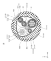
- FIG. 1 is a cross-sectional view in a plane perpendicular to the longitudinal direction of a cable according to one aspect of the present disclosure
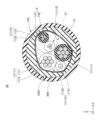
- FIG. FIG. 2 is a cross-sectional view in a plane perpendicular to the longitudinal direction of a cable according to one aspect of the present disclosure
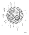
- FIG. 3 is a cross-sectional view in a plane perpendicular to the longitudinal direction of a cable according to one aspect of the present disclosure
- FIG. 4 is a cross-sectional view in a plane perpendicular to the longitudinal direction of a cable according to one aspect of the present disclosure
- FIG. 5 is a cross-sectional view in a plane perpendicular to the longitudinal direction of a cable according to one aspect of the present disclosure
- FIG. 1 is a cross-sectional view in a plane perpendicular to the longitudinal direction of a cable according to one aspect of the present disclosure
- FIG. 2 is a cross-sectional view in a plane perpendicular to the longitudinal direction of a cable according to one
- FIG. 6 is a cross-sectional view in a plane perpendicular to the longitudinal direction of a cable according to one aspect of the present disclosure
- FIG. 7A is an explanatory diagram of a state in which a cable is fixed by a fixture according to one aspect of the present disclosure
- FIG. 7B is an explanatory diagram of a state in which a cable is fixed by a fixture according to one aspect of the present disclosure
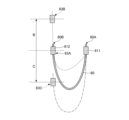
- FIG. 8 is an explanatory diagram of a bending endurance test.
- Cables mounted on automobiles are fixed to the vehicle body at several points. Depending on the wiring location of the cable, the cable may be repeatedly bent at the location where it is fixed to the vehicle body. In addition, when the cable is bent, force may be concentrated on the fixed portion of the cable, resulting in disconnection.
- the purpose of the present disclosure is to provide a cable that can suppress breakage even when repeatedly bent.
- a cable according to an aspect of the present disclosure includes a plurality of coated wires, a jacket that covers the plurality of covered electric wires,
- the outer cover includes a first outer cover and a second outer cover in order from the outer surface side,
- the second jacket has a lower elastic modulus than the first jacket.
- the second outer covering By making the modulus of elasticity of the second outer covering located on the inner peripheral side of the outer covering smaller than that of the first outer covering positioned on the outer peripheral side, even when force is applied to the cable and it is repeatedly bent, the second outer covering can be The outer cover can be deformed to absorb force. Therefore, it is possible to suppress the force applied to the plurality of covered wires by bending, and to suppress the broken wires of the covered wires even when the cable is repeatedly bent.
- the jacket has the function of protecting the covered wires inside the cable.
- the jacket includes at least two layers of the first jacket and the second jacket as described above, and the second jacket functions as a layer for absorbing the force applied to the cable, so that the first jacket It is possible to increase the mechanical strength of the cable by increasing the elastic modulus of the cable. Cables wired in automobiles are required to have abrasion resistance against rubbing against the vehicle body, scratch resistance against being damaged by being hit by flying stones, etc., and flex resistance with little deterioration even after repeated bending. These requirements can be met by increasing the mechanical strength of the jacket.
- the modulus of elasticity of the second jacket may be 40% or more and 80% or less of the modulus of elasticity of the first jacket.
- the elastic modulus of the second jacket By setting the elastic modulus of the second jacket to 80% or less of the elastic modulus of the first jacket, the flexibility of the cable can be increased, and when force is applied to the cable and the cable is repeatedly bent, the force applied to the cable can be absorbed. It is possible to prevent disconnection of the covered electric wire.
- the second jacket By setting the elastic modulus of the second jacket to 40% or more of the elastic modulus of the first jacket, the second jacket can be manufactured by extrusion molding. Therefore, it is possible to increase the productivity of the cable and suppress the cost.
- the modulus of elasticity of the first jacket may be 33 MPa or more and 55 MPa or less.
- the cable can have flexibility suitable for wiring in automobiles.
- the mechanical strength of the first jacket can be sufficiently high for use in automotive wiring.
- the second jacket may be a foam.
- the second jacket By making the second jacket a foam material, the second jacket can be easily deformed, and when external pressure is partially applied to the cable, the pressure is received and the second jacket collapses to absorb the pressure. be able to.
- the plurality of covered wires may include the covered wires with different conductor cross-sectional areas.
- the plurality of covered wires may include two covered wires having the same conductor cross-sectional area, and the two covered wires may be twisted together.
- a twisted pair wire which is made by twisting two coated wires with the same conductor cross-sectional area, can be used as a wire for signal transmission (signal wire) such as a sensor wire. Twisted pair electric wires have the advantage of being able to suppress deterioration and attenuation of transmitted signals. Moreover, the twisted pair electric wire has the advantage that two wires can be handled collectively when they are wired to the same place, which facilitates the wiring.
- the roundness of the outer periphery of the second outer cover may be 97% or more.
- the outer shape of the cable can be rounded.
- the outer shape of the cable is round, i.e. close to a perfect circle, which suppresses the formation of a gap between the cable and the inlet of the separate member, and strengthens the cable. can be fixed.
- the outer shape of the cable is round, when the cable is introduced into the housing of the device, it is possible to easily seal the introduction portion between the cable and the housing, thereby preventing the occurrence of a gap between the cable and the housing. can be prevented.
- FIG. 1 shows a cross-sectional view of the cable 10 of this embodiment in a plane perpendicular to the longitudinal direction.
- 2 to 6 show cross-sectional views of the cables 20 to 60 of the present embodiment on planes perpendicular to the longitudinal direction.
- 2 to 6 are modified examples of the configuration of the sheathed wire and jacket of the cable of this embodiment, so the cable of this embodiment will be described mainly using FIG. 1, and if necessary Description will be made with reference to FIGS. 2 to 6.
- FIG. 7A and 7B are explanatory diagrams of a state in which the cable 70 of this embodiment is fixed by a fixture 71.
- FIG. FIG. 7A corresponds to a cross-sectional view taken along line AA in FIG. 7B.
- the Z-axis direction is the longitudinal direction of the cable or coated wire
- the XY plane is the cross section perpendicular to the longitudinal direction of the cable.
- the cable 10 of this embodiment has a plurality of covered wires 11 and a jacket 13 that covers the plurality of covered wires 11 .
- the cable 10 shown in FIG. 1 shows an example of having two first covered wires 111 and two second covered wires 112 as the covered wires 11, but the cable of this embodiment has a plurality of wires
- the configuration of the coated wire is not limited to such a form.
- the cable of this embodiment can include any number of covered wires, and the combination of types of covered wires included in the cable can be arbitrarily selected.
- the covered wire 11 is a wire that performs functions required in equipment, such as power supply, voltage application, and communication, and is a wire that is subject to disconnection suppression. As described above, the number and configuration of the coated wires 11 are not particularly limited.
- the covered electric wire 11 can have a conductor and an insulator covering the outer circumference of the conductor.
- the conductor may be a stranded wire in which a plurality of conductor strands are twisted.
- the first covered electric wire 111 has a conductor 1111 that is a strand of conductor wires 1111A and an insulator 1112 that covers the outer periphery of the conductor 1111 .
- the first coated wire 111 can be, for example, a power wire intended to supply current.
- the second covered electric wire 112 has a conductor 1121 that is a strand of conductor strands 1121A and an insulator 1122 that covers the outer periphery of the conductor 1121 .
- the second coated wire 112 can be a signal wire intended for signal transmission, for example.
- the cable 10 shown in FIG. be able to.
- the cable including the covered wires 11 having different conductor cross-sectional areas in this way, the cable can be applied to various uses.
- the conductor cross-sectional area of the first covered wire 111 can be made larger than the conductor cross-sectional area of the second covered wire 112 .
- the conductor cross-sectional area of the covered wire 11 is the sum of the cross-sectional areas of the conductor strands 1111A forming the conductor 1111.
- the cross-sectional area of the conductor is the sum of the cross-sectional areas of the conductor strands 1121A forming the conductor 1121.
- the cable 20 shown in FIG. 2 has two first covered wires 111 , two second covered wires 112 , and two third covered wires 113 as the covered wires 11 .
- the third covered electric wire 113 has a conductor 1131 and an insulator 1132 covering the conductor 1131 .
- the third covered electric wire 113 shows an example in which a single wire is used instead of a twisted wire as the conductor 1131, but the present invention is not limited to such a form, and a plurality of conductor strands are twisted together as the conductor 1131. A twisted wire can also be used.
- the plurality of covered wires 11 includes the second covered wires 112 which are two covered wires 11 having the same conductor cross-sectional area.
- the second covered wires 112, which are the two covered wires 11, may be twisted together. That is, the second coated wire 112 can also be the twisted pair wire 21 .
- a twisted pair wire (twisted pair wire) obtained by twisting two coated wires 11 having the same conductor cross-sectional area can be used as a wire for signal transmission (signal wire) such as a sensor wire.
- Twisted pair electric wires have the advantage of being able to suppress deterioration and attenuation of transmitted signals.
- the twisted pair electric wire has the advantage that two wires can be handled collectively when they are wired to the same place, which facilitates the wiring.
- the cable 30 shown in FIG. 3 has two first covered wires 111 , two second covered wires 112 and one third covered wire 113 as the covered wires 11 .
- the cable 30 can have the same configuration as the cable 20 shown in FIG. 2 except that the number of the third covered wires 113 is different.
- the cable 40 shown in FIG. 4 has two first covered wires 111 and four second covered wires 112 as the covered wires 11 .
- the twisted pair electric wire 21 can be formed by twisting two of the four second covered electric wires 112 together.
- the cable of the present embodiment may also include multiple pairs of twisted coated wires.
- two twisted pair electric wires 21 are arranged at symmetrical positions with a virtual line L40 connecting the centers of two first covered electric wires 111 as an axis of symmetry.
- the aggregate diameter of the covered electric wires 11 included in the cable 40 is made as small as possible, and the outer shape of the twisted covered electric wires 11 is made as round as possible.
- the cable 50 shown in FIG. 5 has two first covered wires 111 , two third covered wires 113 , and two fourth covered wires 114 as the covered wires 11 .
- the fourth covered electric wire 114 has a conductor 1141 that is a stranded conductor wire and an insulator 1142 that covers the outer circumference of the conductor 1141 .
- the two third coated wires 113 having the same conductor cross-sectional area are also twisted together to form a twisted pair wire 51 .
- a coating 52 may be provided to cover the twisted pair electric wires 51 .
- FIG. 5 shows an example in which a first coating 521 and a second coating 522 are arranged from the twisted pair electric wire 51 side as the coating 52 .
- the coating 52 can be composed of one layer, or can be composed of three or more layers.
- thermoplastic polyurethane elastomer ethylene-vinyl acetate copolymer (EVA), ethylene-ethyl acrylate copolymer (EEA), etc.
- EVA ethylene-vinyl acetate copolymer
- ESA ethylene-ethyl acrylate copolymer
- thermoplastic polyurethane elastomer for example, a thermoplastic polyurethane elastomer or the like can be suitably used.
- the coating 52 may be obtained by coating the twisted pair electric wires 51 with an insulating resin by solid extrusion molding as shown in FIG. 5, or may be a resin tube (not shown).
- the wire diameter and the number of conductor strands constituting the conductor of the covered electric wire can be selected according to the electrical characteristics required for each covered electric wire.
- the wire diameter of the conductor wire of the covered electric wire 11 is preferably 0.05 mm or more and 0.16 mm or less, and more preferably 0.05 mm or more and 0.10 mm or less.
- the power line can also be made into a conductor by twisting conductor strands in multiple stages.
- the conductor of a power supply wire consists of a first strand (child strand) made by twisting conductor strands and a second strand (parent strand) made by twisting a plurality of first strands.
- a third stranded wire obtained by further twisting a plurality of second stranded wires can also be used as a conductor.
- the first strand may be referred to as a grand-twist
- the second strand as a child-twist
- the third strand as a parent-twist.
- the signal line can also be made into a conductor by twisting conductor strands in multiple stages. That is, the conductor of the signal line has a first twisted wire (child twisted wire) in which conductor strands are twisted together, and a second twisted wire (parent twisted wire) in which a plurality of first twisted wires are twisted together.
- the second stranded wire can be used as a conductor, or a third stranded wire, for example, which is obtained by further twisting a plurality of second stranded wires, can be used as a conductor.
- the conductor strands of the signal line can be single twisted, and the first twisted wire can be the conductor.
- the wire diameter of a wire such as a conductor wire can be measured and calculated by, for example, the following procedure.
- the wire diameter of the wire is measured with a micrometer along two diameters of the wire that are perpendicular to each other in an arbitrary cross section perpendicular to the longitudinal direction of the wire. Then, the average value can be used as the wire diameter of the wire. In this specification, the wire diameter of the wire can be similarly measured and calculated.
- the cable has a power line and a signal line as the covered electric wire 11
- a form in which the conductor cross-sectional area of the conductor of the power line is 1.5 mm 2 or more and 3.5 mm 2 or less can be exemplified.
- a form in which the conductor cross-sectional area of the conductor included in the signal line is 0.1 mm 2 or more and 0.5 mm 2 or less can be exemplified.
- the conductor cross-sectional area of the conductor of the power line is preferably larger than the conductor cross-sectional area of the conductor of the signal line. More preferably, the cross-sectional area of the conductor of the power line is 3 to 15 times the cross-sectional area of the conductor of the signal line.
- the material of the conductor wire of the covered electric wire 11 is not particularly limited, but examples thereof include copper, aluminum, copper alloy, and aluminum alloy.
- the conductor wire may be plated with silver or tin on its surface. Therefore, for example, a silver-plated copper alloy, a tin-plated copper alloy, or the like can be used as the material of the conductor wire.
- the insulator material is also not particularly limited, but examples include polytetrafluoroethylene (PTFE), tetrafluoroethylene-perfluoroalkyl vinyl ether copolymer (PFA), tetrafluoroethylene-hexafluoropropylene copolymer (FEP), One or more resins selected from fluororesins such as ethylene-tetrafluoroethylene copolymer (ETFE), polyester resins such as polyethylene terephthalate (PET), and polyolefin resins such as polyethylene and polypropylene can be used.
- the insulating resin may or may not be crosslinked.
- the insulator may contain additives such as flame retardants, flame retardant aids, antioxidants, lubricants, colorants, reflection imparting agents, masking agents, processing stabilizers and plasticizers, in addition to the above resins.
- (core) Cable 10 can contain a core 10A that includes a plurality of coated wires 11 .
- the core 10A can be configured by twisting together the above-described multiple covered wires 11, specifically two first covered wires 111 and two second covered wires 112 along the longitudinal direction.
- cables 20 to 50 can also contain cores.
- the cable 20 has a core 20A in which two first covered wires 111, two second covered wires 112, and two third covered wires 113 are twisted together along the longitudinal direction. Note that the two second coated wires 112 are pre-twisted together as described above.
- the cable 30 has a core 30A in which two first covered wires 111, two second covered wires 112, and one third covered wire 113 are twisted together along the longitudinal direction. Note that the two second coated wires 112 are pre-twisted together as described above.
- the cable 40 has a core 40A in which two first covered wires 111 and four second covered wires 112 are twisted together along the longitudinal direction. It should be noted that the second covered electric wires 112 are pre-twisted two by two as described above.
- the cable 50 has a core 50A in which two first covered wires 111, two third covered wires 113, and two fourth covered wires 114 are twisted together along the longitudinal direction. Note that the two third covered wires 113 are pre-twisted together as described above.
- the arrangement of the plurality of covered wires 11 constituting the core is not particularly limited. Arrangement etc. can be selected.
- the twist direction and twist pitch of the core are not particularly limited and can be selected arbitrarily.
- the cable 10 can have a jacket 13 that covers a plurality of covered wires.
- the cable 70 may be fixed to the vehicle body of the automobile by a fixture 71 as shown in FIGS. 7A and 7B, for example.
- the minor axis D71 of the fixture 71 is adjusted to be shorter than the outer diameter of the cable 70 before fixation at the portion of the fixture 71 where the cable 70 is fixed.
- the cable 70 is tightened.
- the minor axis D71 of the fixture 71 is tightened so as to be approximately 10% or more and 20% or less shorter than the outer diameter of the cable 70 before being fixed. Therefore, the cable 70 may be pressed by the fixture 71 and fixed in a deformed state.
- FIG. 7A corresponds to a cross section perpendicular to the longitudinal direction of the cable 70
- FIG. 7B corresponds to a perspective view of the cable 70.
- FIG. 7A the description of the covered electric wire and the like that constitute the cable 70 is omitted.
- the length L71 (see FIG. 7B) of the fixture 71 in the longitudinal direction of the cable 70 is usually selected to be, for example, about 1 to 3 times the outer diameter of the cable 70 .
- the jacket 13 of the cable 10 of this embodiment includes a first jacket 131 and a second jacket 132 in order from the outer surface 13A side.
- the first jacket 131 is a layer that includes the outer surface 13A of the jacket 13, and is the layer that is arranged on the outermost side.
- the second jacket 132 is a layer arranged closer to the core 10A than the first jacket 131 is.
- the outer cover 13 is not limited to having only two layers, the first outer cover 131 and the second outer cover 132, and may be composed of three or more layers.
- the jacket 13 can also have a third jacket 133 (see cable 60 in FIG. 6) or the like, for example, closer to the core 10A than the second jacket 132 .
- the elastic modulus of the second outer cover 132 of the outer cover 13 is made smaller than that of the first outer cover 131 .
- the jacket 13 has the function of protecting the covered wire 11 inside the cable 10 .
- the jacket 13 includes at least two layers of the first jacket 131 and the second jacket 132 as described above, and the second jacket 132 functions as a layer for absorbing the force applied to the cable, It is possible to increase the mechanical strength of the cable 10 by increasing the elastic modulus of the first jacket 131 . Cables wired in automobiles are required to have abrasion resistance against rubbing against the vehicle body, scratch resistance against being damaged by stepping stones, etc., and bending resistance with little deterioration even after repeated bending. These requirements can be met by increasing the mechanical strength of the jacket 13 .
- the elastic modulus means the tensile elastic modulus measured at 23°C.
- the elastic modulus of the first jacket 131 is not particularly limited as long as it is higher than the elastic modulus of the second jacket 132, but the elastic modulus of the first jacket 131 is preferably 33 MPa or more and 55 MPa or less.
- the cable 10 can have flexibility suitable for wiring in automobiles.
- the mechanical strength of the first jacket 131 can be sufficiently high enough to be used for automotive wiring.
- the material of the first jacket 131 is not particularly limited, the first jacket 131 can contain thermoplastic polyurethane elastomer, for example.
- the resin of the first jacket 131 may or may not be crosslinked.
- the first jacket 131 may contain additives such as flame retardants, flame retardant auxiliaries, antioxidants, lubricants, colorants, reflection imparting agents, masking agents, processing stabilizers, plasticizers, etc., in addition to the above resins. can. (Second outer cover)
- the modulus of elasticity of the second jacket 132 can be less than the modulus of elasticity of the first jacket 131 as described above.
- the elastic modulus of the second outer cover 132 is preferably 40% or more and 80% or lower than that of the first outer cover 131, for example. This range of elastic modulus can be achieved by using a material having an elastic modulus within this range or by adjusting the degree of foaming of the second jacket.
- the flexibility of the cable 10 can be increased, and when force is applied to the cable 10 and the cable 10 is repeatedly bent, the cable 10 It is possible to absorb the force applied to the covered wire 11 and prevent breakage of the covered wire 11 .
- the second outer cover 132 By setting the elastic modulus of the second outer cover 132 to 40% or more of the elastic modulus of the first outer cover 131, the second outer cover 132 can be manufactured by extrusion molding. Therefore, the productivity of the cable 10 can be improved and the cost can be suppressed.
- the second jacket 132 can contain, for example, a thermoplastic polyurethane elastomer, and can also contain a foamed thermoplastic polyurethane elastomer.
- the resin of the second jacket 132 may or may not be crosslinked.
- the second jacket 132 may contain additives such as flame retardants, flame retardant auxiliaries, antioxidants, lubricants, colorants, reflection imparting agents, masking agents, processing stabilizers, and plasticizers in addition to the above resins. can.
- the second jacket 132 can also be made of foam.
- the second jacket 132 By making the second jacket 132 a foam material, the second jacket 132 can be easily deformed, and when external pressure is partially applied to the cable 10, the pressure is received and the second jacket 132 is crushed. Can absorb pressure.
- the roundness of the outer circumference 132A of the second jacket 132 in the cross section perpendicular to the longitudinal direction of the cable 10 is not particularly limited, but is preferably 97% or more.
- the outer shape of the cable 10 can be made round, for example, almost a perfect circle.
- the outer shape of the cable 10 is round, i.e. close to a perfect circle, thereby suppressing the formation of a gap between the cable 10 and the take-in port of the separate member. 10 can be firmly fixed.
- the outer shape of the cable 10 is round, when the cable 10 is introduced into the housing of the device, it is possible to easily seal the gap between the cable 10 and the housing at the introduction part, and a gap is generated between the housing. can be prevented.
- the method of setting the roundness of the outer circumference 132A of the second outer cover 132 to the above range is not particularly limited, but for example, the method of providing the third outer cover 133 described below, or the thickness of the second outer cover 132 is sufficiently increased. and adjusting the roundness of the second jacket 132 .
- Roundness can be obtained by taking the ratio of the diameters in the two orthogonal directions in an arbitrary cross section perpendicular to the longitudinal direction of the cable.
- the circularity of the outer circumference 132A of the second jacket 132 is preferably measured and calculated in a plurality of cross sections perpendicular to the longitudinal direction of the cable, and the average value of the circularities calculated in the plurality of cross sections is preferable. .
- the outer diameter of second jacket 132 is measured along the X and Y axes,
- the circularity of the outer circumference 132A of the second jacket 132 in the cross section which is the ratio to the diameter, is calculated.
- the roundness of the outer circumference 132A of the second jacket 132 in a plurality of other cross sections is calculated, and the average value of the measured roundnesses in the plurality of cross sections is calculated. It can be the circularity of the perimeter 132A.
- the directions of the X-axis and the Y-axis are constant. That is, it is preferable to fix the XYZ axes over the entire length of the cable 10 to be measured and perform the evaluation according to the above procedure.
- the distance between multiple cross-sections to be evaluated is constant.
- the number of cross sections to be evaluated is not particularly limited, and is preferably three or more, for example.
- the roundness is, for example, 97% or more and 103% or less.
- the jacket 13 can include not only the two layers of the first jacket 131 and the second jacket 132, but also three or more layers.
- the jacket 13 can also have a third jacket 133 .
- the third outer cover 133 can be arranged closer to the core 10A than the second outer cover 132, for example, as shown in FIG. Since the cable 60 shown in FIG. 6 has the same structure as the cable 10 shown in FIG. 1 except that the jacket 13 has the third jacket 133, description of other points is omitted.
- the roundness of the cable can be improved.
- the material of the third outer cover 133 is not particularly limited, but may be thermoplastic polyurethane elastomer (TPU), polyolefin resin such as ethylene-vinyl acetate copolymer resin (EVA) or ethylene-ethyl acrylate copolymer resin (EEA).
- TPU thermoplastic polyurethane elastomer
- EVA ethylene-vinyl acetate copolymer resin
- ESA ethylene-ethyl acrylate copolymer resin
- the resin of the third jacket 133 may or may not be crosslinked.
- the third outer cover 133 may contain additives such as flame retardants, flame retardant auxiliaries, antioxidants, lubricants, colorants, reflection imparting agents, masking agents, processing stabilizers, plasticizers, etc., in addition to the above resins. can.
- additives such as flame retardants, flame retardant auxiliaries, antioxidants, lubricants, colorants, reflection imparting agents, masking agents, processing stabilizers, plasticizers, etc., in addition to the above resins. can.
- the cable 10 of the present embodiment can also have a restraining winding 12 covering the outer periphery of the core 10A.
- the restraint winding 12 is suitably exemplified by spirally winding a tape body made of an insulating material such as paper, non-woven fabric, or resin such as polyester around the outer periphery of the core 10A along the longitudinal direction of the core 10A. can.
- the restraining winding 12 By arranging the restraining winding 12 on the outer periphery of the core 10A, it is possible to prevent the core 10A and the jacket 13 from coming into direct contact with each other. Then, the jacket 13 can be peeled off from the core 10A.
- the winding direction of the restraining winding 12 can be arbitrarily selected. , or in a different direction. In particular, it is preferable that the twist direction of the core 10A and the winding direction of the restraint winding 12 are the same.
- the winding pitch of the restraining winding 12 is shorter than the twisting pitch of the core 10A.
- the tape body forming the restraining winding 12 in the concave portion formed between the plurality of covered electric wires 11 constituting the core 10A is formed. This is because the surface of the hold-down winding 12 can be made smooth by suppressing the drop.
- the cable 10 of the present embodiment can also have an interposition arranged within the region surrounded by the jacket 13, for example, within the core 10A.
- the interposer can be composed of fibers such as staple yarns or nylon yarns.
- the interposer may be composed of tensile strength fibers.
- the arrangement of the covered wires 11 is adjusted, and in the cross section perpendicular to the longitudinal direction of the cable 10, the circumscribed circle of the core 10A and the jacket 13 are formed. It is also possible to easily adjust the shape of the outer surface of each layer to make it closer to a perfect circle.
- the cable of this embodiment can be used for various applications where force is applied to the cable and it may bend repeatedly.
- the cable of the present embodiment is suitable for use in a device such as an automobile, in which the cable is frequently bent or vibrated by movement, for example, an electric parking brake that is an electric parking brake.
- an electric parking brake that is an electric parking brake.
- the electric brake system in which the foot brake of an automobile is electrified, the effect that can occur when the coated wire is broken is large, and it is suitable for applications where it is particularly required to suppress the broken wire of the covered wire.
- the power line is configured to supply power for driving the motor
- the signal line is configured to transmit electrical signals related to motor control and wheel rotation speeds. .
- the outer cover 13 includes the third outer cover
- the third outer cover can be similarly cut out. At this time, each layer is carefully cut into pieces so that the maximum thickness of each layer remains.
- test piece for measuring the tensile modulus in accordance with ISO527 is produced.
- the thickness of the test piece for measuring the tensile modulus is preferably as thick as can be cut from the cable.
- the width and length of the test piece the distance between gauge lines of 50 mm and the width of 10 mm are maintained, and the other sizes are the standard values or sizes as close as possible to the standard values.
- the 0.25% secant elastic modulus at 23°C of the prepared test piece is measured, and the tensile elastic modulus of the test piece is obtained.
- the first end portion 80A side of the cable 80 to be evaluated is gripped and fixed by the first blanket 811 .
- the first blanket 811 is fixed so that it does not move during the bending endurance test.
- the second blanket 812 grips the second end 80B side of the cable 80 .
- the cable 80 between the first blanket 811 and the second blanket 812 should be 200 mm.
- the second end portion 80B side of the cable 80 gripped by the second blanket 812 is configured to be vertically movable.
- the second blanket 812 is vertically moved from the reference position 83A along the arrows B and C in FIG. 8 to bend the cable 80 repeatedly.
- the reference position 83A is located at the same height as the first blanket 811. When the first blanket 811 and the second blanket 812 are in the reference position, the distance between them is 100 mm.
- the above-described bending can be repeated by sequentially moving the second blanket 812 from the reference position 83A to the upper end 83B, the reference position 83A, the lower end 83C, and the reference position 83A. Regarding the above operations, the order of the upper end 83B and the lower end 83C can be changed.
- the distance between the reference position 83A and the upper end 83B and the distance between the reference position 83A and the lower end 83C are set to be equal and constant even when repeatedly bent. If the length of the cable 80 between the first blanket 811 and the second blanket 812 is 200 mm, the distance from the reference position to the upper end or lower end should be 80 mm.
- the above operation of repeatedly bending the cable 80 is performed while measuring the resistance values of the conductors of all the covered wires 11 in the cable 80 . Then, the number of bends of any of the conductors of the covered wire 11 until the resistance rises to 10 times or more of the initial resistance value is recorded and used as an index value for the bend endurance test.
- the index value of the bending resistance test that is, the higher the number of times of bending, the better the bending resistance.
- the cable produced has the same configuration as the cable 60 shown in FIG. 6 except that the two second coated wires 112 are twisted together, so the description will be made using FIG.
- the core 10A includes two first covered wires 111 and two second covered wires 112.
- the first covered electric wire 111 has a conductor 1111 that is a twisted wire of conductor strands 1111A and an insulator 1112 that covers the outer circumference of the conductor 1111 .
- the wire diameter of the conductor wire 1111A is 0.08 mm, and the conductor cross-sectional area of the conductor 1111 is 1.7 mm 2 .
- the insulator 1112 is made of polyethylene and has an outer diameter of 2.7 mm.
- the second covered electric wire 112 has a conductor 1121 that is a strand of conductor strands 1121A and an insulator 1122 that covers the outer circumference of the conductor 1121 .
- the wire diameter of the conductor wire 1121A is 0.08 mm, and the conductor cross-sectional area of the conductor 1121 is 0.24 mm 2 .
- the insulator 1122 is made of polyethylene and has an outer diameter of 1.5 mm.
- the two first covered wires 111 and the two second covered wires 112 are twisted together to form the core 10A. As described above, the two second covered wires 112 are pre-twisted, unlike the case shown in FIG.
- a tape body is wound around the outer circumference of the core 10A to form a restraining winding 12, and a jacket 13 is arranged so as to cover the outer circumference of the restraining winding 12.
- the outer cover 13 includes a first outer cover 131, a second outer cover 132, and a third outer cover 133 in order from the outer surface 13A side.
- the first jacket 131 is made of thermoplastic polyurethane elastomer.
- the thickness of the first jacket 131 is 0.2 mm.
- the second jacket 132 is made of foamed thermoplastic polyurethane elastomer, and the thickness of the second jacket 132 is 0.5 mm.
- the second jacket is made of the same resin as the first jacket, but differs in that it is foamed.
- the elastic modulus of the second jacket was 50% of the elastic modulus of the first jacket.
- the third jacket 133 is made of the same thermoplastic polyurethane elastomer as the first jacket 131.
- the thickness of the third jacket 133 was 0.3 mm.
Landscapes
- Insulated Conductors (AREA)
Priority Applications (4)
| Application Number | Priority Date | Filing Date | Title |
|---|---|---|---|
| CN202280090807.1A CN118786492A (zh) | 2022-02-17 | 2022-02-17 | 线缆 |
| PCT/JP2022/006429 WO2023157190A1 (ja) | 2022-02-17 | 2022-02-17 | ケーブル |
| JP2024500825A JP7786544B2 (ja) | 2022-02-17 | 2022-02-17 | ケーブル |
| US18/832,689 US20250095877A1 (en) | 2022-02-17 | 2022-02-17 | Cable |
Applications Claiming Priority (1)
| Application Number | Priority Date | Filing Date | Title |
|---|---|---|---|
| PCT/JP2022/006429 WO2023157190A1 (ja) | 2022-02-17 | 2022-02-17 | ケーブル |
Publications (1)
| Publication Number | Publication Date |
|---|---|
| WO2023157190A1 true WO2023157190A1 (ja) | 2023-08-24 |
Family
ID=87577896
Family Applications (1)
| Application Number | Title | Priority Date | Filing Date |
|---|---|---|---|
| PCT/JP2022/006429 Ceased WO2023157190A1 (ja) | 2022-02-17 | 2022-02-17 | ケーブル |
Country Status (4)
| Country | Link |
|---|---|
| US (1) | US20250095877A1 (https=) |
| JP (1) | JP7786544B2 (https=) |
| CN (1) | CN118786492A (https=) |
| WO (1) | WO2023157190A1 (https=) |
Citations (3)
| Publication number | Priority date | Publication date | Assignee | Title |
|---|---|---|---|---|
| JP2019129005A (ja) * | 2018-01-22 | 2019-08-01 | 住友電気工業株式会社 | 被覆電線および多芯ケーブル |
| WO2020044850A1 (ja) * | 2018-08-27 | 2020-03-05 | 住友電気工業株式会社 | 電気絶縁ケーブル |
| WO2020241508A1 (ja) * | 2019-05-28 | 2020-12-03 | 住友電気工業株式会社 | 多芯ケーブル |
Family Cites Families (2)
| Publication number | Priority date | Publication date | Assignee | Title |
|---|---|---|---|---|
| JP2000322934A (ja) | 1999-05-12 | 2000-11-24 | Toyobo Co Ltd | 電 線 |
| JP6615412B2 (ja) | 2017-12-27 | 2019-12-04 | 古河電気工業株式会社 | アルミニウム合金材並びにこれを用いたケーブル、電線及びばね部材 |
-
2022
- 2022-02-17 WO PCT/JP2022/006429 patent/WO2023157190A1/ja not_active Ceased
- 2022-02-17 JP JP2024500825A patent/JP7786544B2/ja active Active
- 2022-02-17 CN CN202280090807.1A patent/CN118786492A/zh active Pending
- 2022-02-17 US US18/832,689 patent/US20250095877A1/en active Pending
Patent Citations (3)
| Publication number | Priority date | Publication date | Assignee | Title |
|---|---|---|---|---|
| JP2019129005A (ja) * | 2018-01-22 | 2019-08-01 | 住友電気工業株式会社 | 被覆電線および多芯ケーブル |
| WO2020044850A1 (ja) * | 2018-08-27 | 2020-03-05 | 住友電気工業株式会社 | 電気絶縁ケーブル |
| WO2020241508A1 (ja) * | 2019-05-28 | 2020-12-03 | 住友電気工業株式会社 | 多芯ケーブル |
Also Published As
| Publication number | Publication date |
|---|---|
| US20250095877A1 (en) | 2025-03-20 |
| CN118786492A (zh) | 2024-10-15 |
| JP7786544B2 (ja) | 2025-12-16 |
| JPWO2023157190A1 (https=) | 2023-08-24 |
Similar Documents
| Publication | Publication Date | Title |
|---|---|---|
| US10661730B2 (en) | Multi-core cable for vehicle | |
| US10340058B2 (en) | Cable with braided shield | |
| US11107603B2 (en) | Multi-core flat cable for vehicle | |
| US10566107B2 (en) | Coated electric wire and multi-core cable for vehicle | |
| JP5322755B2 (ja) | ケーブル | |
| US11515063B2 (en) | Composite cable | |
| US10269468B1 (en) | Cable with braided shield | |
| JP2018022633A (ja) | 車両用の多芯ケーブル | |
| US10734137B2 (en) | Composite cable | |
| CN114746959A (zh) | 多芯电缆 | |
| JP2020024949A (ja) | 被覆電線および車両用の多芯ケーブル | |
| JP2023141013A (ja) | シールド付き対撚り電線 | |
| WO2023157190A1 (ja) | ケーブル | |
| JP6569923B2 (ja) | 編組シールド付ケーブル | |
| JP7188517B2 (ja) | 複合ケーブル | |
| JP4821983B2 (ja) | 電気ケーブル | |
| JP6838679B2 (ja) | ケーブル | |
| JP7264170B2 (ja) | 電気絶縁ケーブル | |
| JP6766928B1 (ja) | 可動部用ケーブル | |
| JP2007080706A (ja) | シールドケーブル | |
| US20260004949A1 (en) | Multicore cable | |
| JP2025148734A (ja) | 複合ケーブル | |
| JP2025036037A (ja) | ケーブル | |
| JP2025067247A (ja) | 同軸電線、多芯ケーブル | |
| JP2019186226A (ja) | 編組シールド付ケーブル |
Legal Events
| Date | Code | Title | Description |
|---|---|---|---|
| 121 | Ep: the epo has been informed by wipo that ep was designated in this application |
Ref document number: 22927092 Country of ref document: EP Kind code of ref document: A1 |
|
| WWE | Wipo information: entry into national phase |
Ref document number: 18832689 Country of ref document: US |
|
| WWE | Wipo information: entry into national phase |
Ref document number: 202280090807.1 Country of ref document: CN |
|
| ENP | Entry into the national phase |
Ref document number: 2024500825 Country of ref document: JP Kind code of ref document: A |
|
| NENP | Non-entry into the national phase |
Ref country code: DE |
|
| 122 | Ep: pct application non-entry in european phase |
Ref document number: 22927092 Country of ref document: EP Kind code of ref document: A1 |
|
| WWP | Wipo information: published in national office |
Ref document number: 18832689 Country of ref document: US |