WO2023157132A1 - 無線通信方法、無線通信システム、及び送信装置 - Google Patents
無線通信方法、無線通信システム、及び送信装置 Download PDFInfo
- Publication number
- WO2023157132A1 WO2023157132A1 PCT/JP2022/006201 JP2022006201W WO2023157132A1 WO 2023157132 A1 WO2023157132 A1 WO 2023157132A1 JP 2022006201 W JP2022006201 W JP 2022006201W WO 2023157132 A1 WO2023157132 A1 WO 2023157132A1
- Authority
- WO
- WIPO (PCT)
- Prior art keywords
- phase shift
- shift amount
- transmission data
- wireless communication
- precoding
- Prior art date
- Legal status (The legal status is an assumption and is not a legal conclusion. Google has not performed a legal analysis and makes no representation as to the accuracy of the status listed.)
- Ceased
Links
Images






Classifications
-
- H—ELECTRICITY
- H04—ELECTRIC COMMUNICATION TECHNIQUE
- H04L—TRANSMISSION OF DIGITAL INFORMATION, e.g. TELEGRAPHIC COMMUNICATION
- H04L27/00—Modulated-carrier systems
- H04L27/18—Phase-modulated carrier systems, i.e. using phase-shift keying
- H04L27/20—Modulator circuits; Transmitter circuits
- H04L27/2032—Modulator circuits; Transmitter circuits for discrete phase modulation, e.g. in which the phase of the carrier is modulated in a nominally instantaneous manner
- H04L27/2053—Modulator circuits; Transmitter circuits for discrete phase modulation, e.g. in which the phase of the carrier is modulated in a nominally instantaneous manner using more than one carrier, e.g. carriers with different phases
- H04L27/206—Modulator circuits; Transmitter circuits for discrete phase modulation, e.g. in which the phase of the carrier is modulated in a nominally instantaneous manner using more than one carrier, e.g. carriers with different phases using a pair of orthogonal carriers, e.g. quadrature carriers
- H04L27/2067—Modulator circuits; Transmitter circuits for discrete phase modulation, e.g. in which the phase of the carrier is modulated in a nominally instantaneous manner using more than one carrier, e.g. carriers with different phases using a pair of orthogonal carriers, e.g. quadrature carriers with more than two phase states
-
- H—ELECTRICITY
- H04—ELECTRIC COMMUNICATION TECHNIQUE
- H04B—TRANSMISSION
- H04B7/00—Radio transmission systems, i.e. using radiation field
- H04B7/02—Diversity systems; Multi-antenna system, i.e. transmission or reception using multiple antennas
- H04B7/04—Diversity systems; Multi-antenna system, i.e. transmission or reception using multiple antennas using two or more spaced independent antennas
- H04B7/0413—MIMO systems
- H04B7/0456—Selection of precoding matrices or codebooks, e.g. using matrices antenna weighting
-
- H—ELECTRICITY
- H04—ELECTRIC COMMUNICATION TECHNIQUE
- H04L—TRANSMISSION OF DIGITAL INFORMATION, e.g. TELEGRAPHIC COMMUNICATION
- H04L27/00—Modulated-carrier systems
- H04L27/26—Systems using multi-frequency codes
- H04L27/2601—Multicarrier modulation systems
- H04L27/2614—Peak power aspects
Definitions
- the present invention relates to wireless communication technology.
- the present invention relates to a radio communication technique in which transmission data is precoded on the transmitting side.
- the transmitting side may precode the transmitted data. For example, when performing wideband transmission under a frequency selective fading environment, channel equalization is performed by precoding. As another example, multiple-input multiple-output (MIMO) systems perform stream separation by precoding.
- MIMO multiple-input multiple-output
- PAPR Peak to Average Power Ratio
- a transmission signal is amplified by a power amplifier before being transmitted from an antenna, and if a signal with a high PAPR is input to the power amplifier, it may be affected by the nonlinear characteristics of the power amplifier and cause nonlinear distortion. The occurrence of nonlinear distortion in the transmitted signal may result in erroneous communication.
- Non-Patent Document 1 discloses a technique for reducing PAPR in a wideband single-carrier MIMO system.
- the PAPR increases.
- One object of the present invention is to provide a technique capable of reducing PAPR when the transmission side precodes transmission data in wireless communication.
- a first aspect relates to a wireless communication method for performing wireless communication between a transmitting device and a receiving device.
- the wireless communication method is Phase shift amount determination processing for determining a random phase shift amount for each symbol of transmission data; A modulation process that modulates transmission data and further shifts the phase according to a random phase shift amount for each symbol; precoding processing for precoding transmission data after modulation processing; and transmission processing for transmitting transmission data after precoding processing from a transmission device to a reception device.
- a second aspect relates to wireless communication systems.
- a wireless communication system includes a transmitter and a receiver.
- the transmitting device Phase shift amount determination processing for determining a random phase shift amount for each symbol of transmission data;
- a modulation process that modulates transmission data and further shifts the phase according to a random phase shift amount for each symbol; precoding processing for precoding transmission data after modulation processing; and a transmission process of transmitting the transmission data after the precoding process from the transmission device to the reception device.
- a third aspect relates to a transmitting device that wirelessly communicates with a receiving device.
- the transmitting device a phase shift amount determining unit that determines a random phase shift amount for each symbol of transmission data; a modulation unit that modulates the transmission data and further shifts the phase according to the random phase shift amount for each symbol; a precoding unit that precodes the transmission data after the modulation process; and a transmitting unit configured to transmit the transmission data after the precoding process to the receiving device.
- the present invention it is possible to reduce the PAPR when the transmission side performs precoding on transmission data in wireless communication.
- FIG. 1 is a conceptual diagram schematically showing the configuration of a radio communication system according to an embodiment
- FIG. FIG. 2 is a block diagram showing a basic configuration example of a transmission device that performs precoding
- FIG. 4 is a conceptual diagram for explaining amplification characteristics of an amplifier
- FIG. 4 is a conceptual diagram for explaining distortion of constellation
- FIG. 4 is a conceptual diagram for explaining the basics of phase shift according to the embodiment
- FIG. 4 is a conceptual diagram for explaining an overview of phase shift according to the embodiment
- FIG. 4 is a conceptual diagram for explaining an example of a random phase shift sequence according to an embodiment
- FIG. FIG. 4 is a conceptual diagram for explaining signal addition processing according to the embodiment
- FIG. 4 is a conceptual diagram for explaining the effect of phase shift according to the embodiment; 4 is a flow chart summarizing processing by a transmitting device according to an embodiment; 1 is a block diagram showing a first configuration example of a transmission device according to an embodiment; FIG. FIG. 10 is a block diagram showing a second configuration example of a transmission device according to an embodiment; FIG. 11 is a block diagram showing a third configuration example of a transmission device according to an embodiment; 1 is a block diagram showing a configuration example of a receiving device according to an embodiment; FIG.
- FIG. 1 is a conceptual diagram schematically showing the configuration of a radio communication system 1 according to this embodiment.
- a wireless communication system 1 includes a transmitter 100 and a receiver 200 .
- the transmitting device 100 and the receiving device 200 perform wireless communication.
- the radio communication system 1 may be a MIMO (Multiple-Input Multiple-Output) system, a SISO (Single-Input Single-Output) system, or others.
- the radio communication system 1 may perform single-carrier transmission, or may perform multi-carrier transmission based on OFDM (Orthogonal Frequency Division Multiplexing) or the like.
- OFDM Orthogonal Frequency Division Multiplexing
- the transmission device 100 precodes the transmission data. Precoding is a well known technique. For example, when performing wideband transmission under a frequency selective fading environment, channel equalization is performed by precoding. As another example, in MIMO systems, stream separation is performed by precoding.
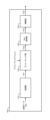
- FIG. 2 is a block diagram showing a basic configuration example of the transmission device 100 that performs precoding.
- Transmitting apparatus 100 includes modulating section 110 , precoding section 120 , D/A converting section 130 and amplifying section 140 .
- the modulation section 110 receives transmission data (transmission signal) TD0 transmitted from the transmission device 100 to the reception device 200 .
- Modulation section 110 performs “modulation processing” for modulating transmission data TD0 using a predetermined modulation scheme. Examples of the predetermined modulation scheme include QAM (Quadrature Amplitude Modulation), QPSK (Quadrature Phase Shift Keying), and the like.
- Modulation section 110 outputs transmission data TD1 after modulation processing.
- the precoding section 120 receives transmission data TD1 after modulation processing.
- the precoding unit 120 performs a “precoding process” for precoding transmission data TD1.
- Various examples are known as precoding weights (precoding matrices) used in precoding processing. In this embodiment, precoding weights are not particularly limited.
- Precoding section 120 outputs transmission data TD2 after precoding processing.
- the D/A converter 130 receives transmission data TD2 after precoding processing.
- D/A converter 130 D/A converts transmission data TD2 and outputs transmission data TD3.
- the amplification unit 140 receives transmission data TD3 after D/A conversion.
- Amplification section 140 includes a power amplifier, and performs “amplification processing” for amplifying transmission data TD3.
- the amplification section 140 performs a "transmission process" for transmitting the amplified transmission data (transmission signal) TD4 to the receiving device 200 via the antenna.
- the amplification unit 140 also functions as a “transmission unit” that performs transmission processing.
- FIG. 3 is a conceptual diagram for explaining the amplification characteristics of the amplification section 140.
- the horizontal axis represents input signal power, and the vertical axis represents output signal power.
- the amplification characteristic includes not only a linear region but also a nonlinear region, and the higher the input signal power, the stronger the influence of the nonlinear characteristic. Even if the average power is in the linear region, an input signal with a high PAPR (Peak to Average Power Ratio) is affected by nonlinear characteristics. As a result, distortion of the constellation of transmitted data may occur.
- PAPR Peak to Average Power Ratio
- FIG. 4 is a conceptual diagram for explaining constellation distortion of transmission data.
- a constellation of transmission data in the case of 64QAM is shown.
- the constellation is distorted in the nonlinear region.
- transmitting apparatus 100 precodes transmission data. Precoding with signal superposition tends to increase PAPR. Therefore, transmission data (transmission signal) with a high PAPR is input to amplification section 140, and may be affected by nonlinear characteristics and generate nonlinear distortion. When nonlinear distortion of transmitted data occurs, there is a risk of error-prone communication.
- the present embodiment provides a technique capable of reducing PAPR when transmitting apparatus 100 precodes transmission data.
- the present embodiment introduces a "phase shift" described below to reduce PAPR.
- FIG. 5 is a conceptual diagram for explaining the basics of the phase shift according to this embodiment.
- the modulation scheme is 64QAM.
- the modulation scheme is not limited to 64QAM.
- the transmission device 100 (modulation section 110) performs modulation processing for modulating transmission data using a predetermined modulation scheme.
- the transmitting apparatus 100 not only modulates the transmission data with a predetermined modulation scheme, but also adds a phase shift to the transmission data.
- the phase shift amount is ⁇ s. That is, in the modulation process, the transmitting apparatus 100 modulates the transmission data using a predetermined modulation method, and further shifts the phase of the transmission data according to the phase shift amount ⁇ s.
- FIG. 6 is a conceptual diagram for explaining the outline of the phase shift according to this embodiment.
- the phase shift amount ⁇ s is determined for each symbol of transmission data, and the phase shift is performed. That is, the phase shift amount ⁇ s is determined separately for each symbol in the time direction, and the phase shift is performed for each symbol according to the phase shift amount ⁇ s.
- the phase shift amount ⁇ s for each symbol is random. That is, transmitting apparatus 100 randomly determines phase shift amount ⁇ s for each symbol of transmission data.
- a random sequence with a phase shift amount ⁇ s is hereinafter referred to as a "random phase shift sequence ⁇ ".
- Random phase shift sequence ⁇ is generated, for example, by transmitting apparatus 100 itself.
- a random phase shift sequence ⁇ generated by another device may be provided to transmitting device 100 .
- Information indicating the random phase shift sequence ⁇ is hereinafter referred to as "phase shift pattern PAT”.
- Transmitter 100 acquires phase shift pattern PAT.
- transmitting apparatus 100 determines a random phase shift amount ⁇ s for each symbol included in a predetermined data unit (eg, frame, slot) based on random phase shift sequence ⁇ indicated by phase shift pattern PAT. Thereafter, transmitting apparatus 100 performs modulation processing according to the determined random phase shift amount ⁇ s, and further performs subsequent processing.
- a predetermined data unit eg, frame, slot
- FIG. 7 is a conceptual diagram for explaining an example of the random phase shift sequence ⁇ according to this embodiment.
- a random phase shift sequence ⁇ of signal length L is used.
- the random phase shift sequence ⁇ includes L random phase shift amounts ⁇ 1 to ⁇ L.
- L is an integer of 2 or more and is predetermined.
- phase shift patterns PAT may be used.
- a plurality of types of phase shift patterns PAT indicate different random phase shift sequences ⁇ .
- transmitting apparatus 100 selects one of a plurality of types of phase shift patterns PAT.
- transmitting apparatus 100 performs modulation processing using each of a plurality of types of phase shift patterns PAT, and further performs subsequent processing.
- Transmitting apparatus 100 then calculates the PAPR of the transmission data after precoding processing by precoding section 120, and selects one of the phase shift patterns PAT with the smallest PAPR from among the plurality of types of phase shift patterns PAT.
- transmitting apparatus 100 obtains information on reception quality (eg, BER (Bit Error Rate)) from receiving apparatus 200, and selects one of the phase shift patterns PAT with the highest reception quality. You can choose from Then, transmitting apparatus 100 determines random phase shift amount ⁇ s for each symbol based on random phase shift sequence ⁇ indicated by one selected phase shift pattern PAT. Thereafter, transmitting apparatus 100 performs modulation processing according to the determined random phase shift amount ⁇ s, and further performs subsequent processing.
- reception quality eg, BER (Bit Error Rate)
- the range that the random phase shift amount ⁇ s can take can be freely set. After the random phase shift amount ⁇ s is generated, rounding to integers may be performed.
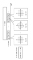
- FIG. 8 is a conceptual diagram for explaining "signal addition processing" according to the present embodiment.
- Receiving apparatus 200 needs to estimate the random phase shift amount ⁇ s (that is, phase shift pattern PAT, random phase shift sequence ⁇ ) applied to transmission data in transmitting apparatus 100 . Therefore, transmitting apparatus 100 adds a known signal to transmission data for use by receiving apparatus 200 in the estimation. More specifically, transmitting apparatus 100 adds a known signal to the beginning or end of a predetermined data unit (eg, frame, slot). In the case of the example shown in FIG. 7 above, a known signal of signal length L is added. The added known signal is also phase-shifted according to the random phase-shift sequence ⁇ .
- a predetermined data unit eg, frame, slot
- the reception device 200 receives the transmission data transmitted from the transmission device 100 as reception data.
- Receiving apparatus 200 estimates a random phase shift amount ⁇ s (that is, phase shift pattern PAT, random phase shift sequence ⁇ ) applied in transmitting apparatus 100 based on a known signal added to received data. Specifically, receiving apparatus 200 estimates the random phase shift amount ⁇ s by comparing the known signal added to the received data with the known signal held by itself. Then, receiving apparatus 200 demodulates the received data in consideration of the estimated phase shift amount ⁇ s. That is, when receiving apparatus 200 demodulates the received data, the phase is returned by the phase shift amount ⁇ s for each symbol included in the received data.
- ⁇ s that is, phase shift pattern PAT, random phase shift sequence ⁇
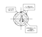
- FIG. 9 is a conceptual diagram for explaining the effect of the phase shift according to this embodiment.
- the distribution of symbol sequences in the constellation approaches a circular shape due to the phase shift. Since the symbol phase that becomes the peak power is shifted, the peak power is reduced when the signal is superimposed by precoding. Furthermore, since zeros are not crossed when transitioning to symbols at point-symmetrical positions, the average power increases compared to the case where no phase shift is performed. In this way, PAPR can be reduced by performing a phase shift during modulation processing of transmission data.
- FIG. 10 is a flow chart that summarizes the processing by transmitting device 100 according to the present embodiment.
- step S110 the transmission device 100 performs "phase shift amount determination processing". That is, transmitting apparatus 100 randomly determines phase shift amount ⁇ s for each symbol included in transmission data of a predetermined data unit (eg, frame, slot). More specifically, transmitting apparatus 100 obtains a phase shift pattern PAT representing a random phase shift sequence ⁇ . Then, transmitting apparatus 100 determines a random phase shift amount ⁇ s for each symbol included in a predetermined data unit, based on random phase shift sequence ⁇ indicated by phase shift pattern PAT.
- a predetermined data unit eg, frame, slot
- transmitting apparatus 100 obtains a phase shift pattern PAT representing a random phase shift sequence ⁇ .
- transmitting apparatus 100 determines a random phase shift amount ⁇ s for each symbol included in a predetermined data unit, based on random phase shift sequence ⁇ indicated by phase shift pattern PAT.
- step S120 the transmission device 100 performs "signal addition processing" on the transmission data. More specifically, transmitting apparatus 100 adds a known signal used for estimating random phase shift amount ⁇ s in receiving apparatus 200 to transmission data.
- step S130 the transmission device 100 performs "modulation processing" on the transmission data. More specifically, transmitting apparatus 100 modulates transmission data using a predetermined modulation scheme, and further shifts the phase according to the random phase shift amount ⁇ s for each symbol. At this time, the known signal added to the transmission data is also phase-shifted.
- step S140 the transmission device 100 performs "precoding processing" on the transmission data. More specifically, transmitting apparatus 100 performs precoding on transmission data after modulation processing.
- step S150 the transmission device 100 performs "transmission processing" for transmitting transmission data after precoding processing from the transmission device to the reception device.
- the transmitting apparatus 100 may appropriately update the phase shift pattern PAT during communication. At the time of updating, the transmitting device 100 may reconsider all kinds of phase shift patterns PAT and select one out of all kinds of phase shift patterns PAT. Alternatively, transmitting apparatus 100 may reconsider only a certain number of phase shift patterns PAT that were relatively good last time, and select one of the certain number of phase shift patterns PAT.
- FIG. 11 is a block diagram showing a first configuration example of the transmitting apparatus 100.
- the transmitting apparatus 100 includes a modulating section 110A, a precoding section 120, a D/A converting section 130, an amplifying section 140, a phase shift amount determining section 150, and a signal adding section 160.
- Modulation section 110A has a phase shift function in addition to the function of modulation section 110 shown in FIG.
- the precoding unit 120, the D/A converting unit 130, and the amplifying unit 140 are similar to those shown in FIG.
- phase shift amount determination unit 150 performs "phase shift amount determination processing". That is, phase shift amount determination section 150 determines a random phase shift amount ⁇ s for each symbol included in transmission data TD0 of a predetermined data unit (eg, frame, slot).
- a predetermined data unit eg, frame, slot
- phase shift amount determination section 150 acquires phase shift pattern PAT representing random phase shift sequence ⁇ . Phase shift amount determination section 150 then determines a random phase shift amount ⁇ s for each symbol based on the random phase shift sequence ⁇ indicated by the phase shift pattern PAT (see FIG. 7). Further, phase shift amount determination section 150 notifies modulation section 110A of random phase shift amount ⁇ s for each symbol.
- the signal addition unit 160 performs "signal addition processing". More specifically, signal adding section 160 adds a known signal used for estimating random phase shift amount ⁇ s in receiving apparatus 200 to transmission data (see FIG. 8). For example, the signal adding section 160 adds a known signal to the beginning or end of a predetermined data unit.
- the modulation section 110A receives from the phase shift amount determination section 150 information on the random phase shift amount ⁇ s for each symbol included in the predetermined data unit. In modulation processing, the modulation section 110A modulates the transmission data TD0 with a predetermined modulation method, and further shifts the phase according to a random phase shift amount ⁇ s for each symbol (see FIG. 7). At this time, the modulation section 110A also phase-shifts the added known signal. Modulation section 110A then outputs transmission data TD1 after modulation processing.
- FIG. 12 is a block diagram showing a second configuration example of the transmitting apparatus 100. As shown in FIG. Descriptions that overlap with the first configuration example shown in FIG. 11 are omitted as appropriate. Transmitting apparatus 100 further includes PAPR calculating section 170 in addition to the first configuration example shown in FIG.
- the phase shift amount determination unit 150 acquires multiple types of phase shift patterns PAT.
- a plurality of types of phase shift patterns PAT indicate different random phase shift sequences ⁇ .
- the phase shift amount determination unit 150 provisionally selects a plurality of types of phase shift patterns PAT one by one.
- the phase shift amount determination section 150 determines a random phase shift amount ⁇ s for each symbol based on the random phase shift sequence ⁇ indicated by the temporarily selected phase shift pattern PAT. Then, phase shift amount determination section 150 notifies modulation section 110A of random phase shift amount ⁇ s for each symbol.
- the modulation section 110A performs modulation processing in the same manner as in the case of the first configuration example.
- Precoding section 120 receives transmission data TD1 after modulation processing.
- Precoding section 120 precodes transmission data TD1 and outputs transmission data TD2.
- the PAPR calculation unit 170 receives transmission data TD2 after precoding processing.
- PAPR calculation section 170 calculates PAPR of transmission data TD2 in a predetermined data unit according to a predetermined calculation formula.
- PAPR calculation section 170 outputs calculated PAPR information to phase shift amount determination section 150 .
- the phase shift amount determination unit 150 acquires PAPR information for each of a plurality of types of phase shift patterns PAT. Then, the phase shift amount determining section 150 selects one of the phase shift patterns PAT with the minimum PAPR from the plurality of types of phase shift patterns PAT. Phase shift amount determination section 150 determines a random phase shift amount ⁇ s for each symbol according to one selected phase shift pattern PAT. Then, phase shift amount determination section 150 notifies modulation section 110A of the determined random phase shift amount ⁇ s for each symbol. Thereafter, the modulation section 110A performs modulation processing using the random phase shift amount ⁇ s notified from the phase shift amount determination section 150.
- FIG. 13 is a block diagram showing a third configuration example of the transmission device 100. As shown in FIG. The description overlapping with the second configuration example shown in FIG. 12 will be omitted as appropriate.
- transmission device 100 includes reception quality information acquisition section 180 instead of PAPR calculation section 170 .
- Reception quality information acquisition section 180 acquires information on reception quality (eg, BER) of transmission data from receiving apparatus 200 .
- Reception quality information acquisition section 180 outputs reception quality information to phase shift amount determination section 150 .
- the phase shift amount determining section 150 acquires reception quality information for each of a plurality of types of phase shift patterns PAT. Then, phase shift amount determining section 150 selects one of the phase shift patterns PAT that provides the highest reception quality. Phase shift amount determination section 150 determines a random phase shift amount ⁇ s for each symbol according to one selected phase shift pattern PAT. Then, phase shift amount determination section 150 notifies modulation section 110A of the determined random phase shift amount ⁇ s for each symbol. Thereafter, the modulation section 110A performs modulation processing using the random phase shift amount ⁇ s notified from the phase shift amount determination section 150. FIG.
- the transmission device 100 includes one or more processors (hereinafter simply referred to as “processors”) and one or more storage devices (hereinafter simply referred to as “storage devices”).
- processors hereinafter simply referred to as "processors”
- storage devices hereinafter simply referred to as “storage devices”.
- the processor includes a CPU (Central Processing Unit).
- the storage device stores various information necessary for processing by the processor. Examples of storage devices include volatile memory, nonvolatile memory, HDD (Hard Disk Drive), SSD (Solid State Drive), and the like.
- the processor may execute a control program, which is a computer program.
- the control program is stored in the storage device.
- the control program may be recorded on a computer-readable recording medium.
- the functions of the processor are realized by the processor executing the control program.
- phase shift patterns PAT prepared in advance Information on a plurality of types of phase shift patterns PAT prepared in advance is stored in the storage device.
- Functions such as modulation section 110A, precoding section 120, phase shift amount determination section 150, signal addition section 160, PAPR calculation section 170, reception quality information acquisition section 180, etc. are realized through cooperation between the processor and the storage device. .
- FIG. 14 is a block diagram showing a configuration example of the receiving device 200 .
- Receiver 200 includes amplifier 210 , A/D converter 220 , and demodulator 230 .
- the reception device 200 receives the transmission data transmitted from the transmission device 100 as reception data (reception signal) RD0.
- Amplifying section 210 amplifies received data RD0 and outputs received data RD1.
- A/D converter 220 A/D-converts received data RD1 and outputs received data RD2.
- the demodulator 230 performs "demodulation processing" for demodulating the received data RD2. At this time, the demodulator 230 demodulates the received data RD2 in consideration of the phase shift amount ⁇ s.
- demodulator 230 includes phase shift amount estimator 240 .
- Phase shift amount estimating section 240 calculates the random phase shift amount ⁇ s (that is, phase shift pattern PAT, random phase shift sequence ⁇ ) applied in transmitting apparatus 100 based on the known signal added to received data RD2. presume. Specifically, the phase shift amount estimator 240 estimates the random phase shift amount ⁇ s by comparing the known signal added to the received data RD2 and the known signal held by itself.
- Demodulator 230 demodulates received data RD2 in consideration of the estimated phase shift amount ⁇ s. That is, the demodulator 230 demodulates the received data RD2 by a predetermined demodulation method, and returns the phase by the phase shift amount ⁇ s for each symbol.
- the receiving device 200 includes one or more processors (hereinafter simply referred to as “processors”) and one or more storage devices (hereinafter simply referred to as “storage devices”).
- the processor may execute a control program, which is a computer program.
- the control program is stored in the storage device.
- the control program may be recorded on a computer-readable recording medium.
- the functions of the processor are realized by the processor executing the control program. Functions such as the demodulator 230 and the phase shift amount estimator 240 are realized by cooperation between the processor and the storage device.
- Radio Communication System 100 Transmitter 110, 110A Modulator 120 Precoder 130 D/A Converter 140 Amplifier 150 Phase Shift Amount Determiner 160 Signal Adder 170 PAPR Calculator 180 Reception Quality Information Acquirer 200 Receiver 210 Amplification Part 220 A/D converter 230 Demodulator 240 Phase shift amount estimator PAT Phase shift pattern
Landscapes
- Engineering & Computer Science (AREA)
- Computer Networks & Wireless Communication (AREA)
- Signal Processing (AREA)
- Digital Transmission Methods That Use Modulated Carrier Waves (AREA)
Priority Applications (4)
| Application Number | Priority Date | Filing Date | Title |
|---|---|---|---|
| US18/833,542 US20250158857A1 (en) | 2022-02-16 | 2022-02-16 | Wireless communication method, wireless communication system, and transmission device |
| PCT/JP2022/006201 WO2023157132A1 (ja) | 2022-02-16 | 2022-02-16 | 無線通信方法、無線通信システム、及び送信装置 |
| EP22927035.0A EP4482047A4 (en) | 2022-02-16 | 2022-02-16 | WIRELESS COMMUNICATION METHOD, WIRELESS COMMUNICATION SYSTEM, AND TRANSMISSION DEVICE |
| JP2024500774A JPWO2023157132A1 (https=) | 2022-02-16 | 2022-02-16 |
Applications Claiming Priority (1)
| Application Number | Priority Date | Filing Date | Title |
|---|---|---|---|
| PCT/JP2022/006201 WO2023157132A1 (ja) | 2022-02-16 | 2022-02-16 | 無線通信方法、無線通信システム、及び送信装置 |
Publications (1)
| Publication Number | Publication Date |
|---|---|
| WO2023157132A1 true WO2023157132A1 (ja) | 2023-08-24 |
Family
ID=87577860
Family Applications (1)
| Application Number | Title | Priority Date | Filing Date |
|---|---|---|---|
| PCT/JP2022/006201 Ceased WO2023157132A1 (ja) | 2022-02-16 | 2022-02-16 | 無線通信方法、無線通信システム、及び送信装置 |
Country Status (4)
| Country | Link |
|---|---|
| US (1) | US20250158857A1 (https=) |
| EP (1) | EP4482047A4 (https=) |
| JP (1) | JPWO2023157132A1 (https=) |
| WO (1) | WO2023157132A1 (https=) |
Families Citing this family (1)
| Publication number | Priority date | Publication date | Assignee | Title |
|---|---|---|---|---|
| US20250141726A1 (en) * | 2022-02-16 | 2025-05-01 | Nippon Telegraph And Telephone Corporation | Wireless communication method, wireless communication system, and transmission device |
Citations (2)
| Publication number | Priority date | Publication date | Assignee | Title |
|---|---|---|---|---|
| JP2009194732A (ja) * | 2008-02-15 | 2009-08-27 | Ntt Docomo Inc | 無線通信装置及び無線通信方法 |
| JP2021048637A (ja) * | 2010-12-10 | 2021-03-25 | サン パテント トラスト | 信号生成方法及び信号生成装置 |
Family Cites Families (3)
| Publication number | Priority date | Publication date | Assignee | Title |
|---|---|---|---|---|
| US20060045193A1 (en) * | 2004-08-24 | 2006-03-02 | Nokia Corporation | System, transmitter, method, and computer program product for utilizing an adaptive preamble scheme for multi-carrier communication systems |
| CN107612597B (zh) * | 2011-02-18 | 2021-01-05 | 太阳专利托管公司 | 信号生成方法及信号生成装置 |
| WO2018059350A1 (zh) * | 2016-09-30 | 2018-04-05 | 华为技术有限公司 | 一种数据处理方法、装置和系统 |
-
2022
- 2022-02-16 US US18/833,542 patent/US20250158857A1/en active Pending
- 2022-02-16 EP EP22927035.0A patent/EP4482047A4/en active Pending
- 2022-02-16 JP JP2024500774A patent/JPWO2023157132A1/ja active Pending
- 2022-02-16 WO PCT/JP2022/006201 patent/WO2023157132A1/ja not_active Ceased
Patent Citations (2)
| Publication number | Priority date | Publication date | Assignee | Title |
|---|---|---|---|---|
| JP2009194732A (ja) * | 2008-02-15 | 2009-08-27 | Ntt Docomo Inc | 無線通信装置及び無線通信方法 |
| JP2021048637A (ja) * | 2010-12-10 | 2021-03-25 | サン パテント トラスト | 信号生成方法及び信号生成装置 |
Non-Patent Citations (3)
| Title |
|---|
| KURIYAMA ET AL.: "PAPR Reduction on Wideband Single-Carrier MIMO Systems with Variable Tap-Length FIR Beamforming", SOCIETY CONFERENCE OF THE INSTITUTE OF ELECTRONICS, INFORMATION AND COMMUNICATION ENGINEERS, September 2021 (2021-09-01), pages B-5 - 70 |
| See also references of EP4482047A4 |
| YUSUKE ISHIDA, SATOSHI SUYAMA, KAZUHIKO FUKAWA, HIROSHI SUZUKI: "B-5-77 PAPR reduction effect of subcarrier phase hopping in MIMO-OFDM with increased number of subcarriers", IEICE 2007 COMMUNICATION SOCIETY CONFERENCE PROCEEDINGS 1; SEPTEMBER 10 - 14, 2007, IEICE, JP, 29 August 2007 (2007-08-29) - 14 September 2007 (2007-09-14), JP, pages 399, XP009548920 * |
Also Published As
| Publication number | Publication date |
|---|---|
| EP4482047A1 (en) | 2024-12-25 |
| US20250158857A1 (en) | 2025-05-15 |
| JPWO2023157132A1 (https=) | 2023-08-24 |
| EP4482047A4 (en) | 2025-12-24 |
Similar Documents
| Publication | Publication Date | Title |
|---|---|---|
| JP4911780B2 (ja) | 無線通信システム、受信装置及び受信方法 | |
| JP6577800B2 (ja) | シングルキャリア方式の送信装置及び受信装置 | |
| JP5218977B2 (ja) | 通信装置、無線通信システムおよびフィードバック情報演算時の近似方法ならびにプログラム | |
| JPWO2010146938A1 (ja) | 移動局装置、基地局装置、通信システム、通信方法および制御プログラム | |
| JP2008206045A (ja) | 無線通信システム及び無線機 | |
| WO2023157132A1 (ja) | 無線通信方法、無線通信システム、及び送信装置 | |
| WO2023157133A1 (ja) | 無線通信方法、無線通信システム、及び送信装置 | |
| JP7782662B2 (ja) | 無線通信方法、無線通信システム、及び送信装置 | |
| WO2023144879A1 (ja) | 無線通信方法、無線通信システム、及び送信装置 | |
| WO2023144882A1 (ja) | 無線通信方法、無線通信システム、及び送信装置 | |
| JP7647900B2 (ja) | 無線通信システム、無線通信方法、および無線通信用送信装置 | |
| US9166841B2 (en) | Receiving apparatus and receiving method | |
| JP7720002B2 (ja) | 無線通信方法、無線通信システム、及び送信装置 | |
| US20140307830A1 (en) | Apparatus and method for offset compensation in high-order modulated orthogonal frequency division multiplexing (ofdm) transmission | |
| WO2023148984A1 (ja) | 無線通信方法、無線通信システムおよび無線送信装置 | |
| CN113055067B (zh) | 下行信号处理方法、装置及基站 | |
| WO2023148954A1 (ja) | 無線通信方法、無線通信システムおよび無線送信装置 | |
| JP7563615B2 (ja) | 無線通信システム、無線通信方法、および無線通信用送信装置 | |
| JP4177879B1 (ja) | 受信装置、送信装置および無線通信システム | |
| JP7613596B2 (ja) | 無線通信方法、無線通信システム、及び送信装置 | |
| JP5216617B2 (ja) | 無線受信機、無線受信方法および無線受信プログラム | |
| JP2023015780A (ja) | 無線通信システム、及び無線通信方法 | |
| WO2024171447A1 (ja) | 無線通信システム、受信装置、無線通信方法、及び受信プログラム | |
| JP2023043653A (ja) | 無線通信装置 | |
| WO2023032153A1 (ja) | 無線通信システム、無線通信方法、及び受信装置 |
Legal Events
| Date | Code | Title | Description |
|---|---|---|---|
| 121 | Ep: the epo has been informed by wipo that ep was designated in this application |
Ref document number: 22927035 Country of ref document: EP Kind code of ref document: A1 |
|
| ENP | Entry into the national phase |
Ref document number: 2024500774 Country of ref document: JP Kind code of ref document: A |
|
| WWE | Wipo information: entry into national phase |
Ref document number: 18833542 Country of ref document: US |
|
| WWE | Wipo information: entry into national phase |
Ref document number: 2022927035 Country of ref document: EP |
|
| NENP | Non-entry into the national phase |
Ref country code: DE |
|
| ENP | Entry into the national phase |
Ref document number: 2022927035 Country of ref document: EP Effective date: 20240916 |
|
| WWP | Wipo information: published in national office |
Ref document number: 18833542 Country of ref document: US |