WO2023153258A1 - コネクタ - Google Patents
コネクタ Download PDFInfo
- Publication number
- WO2023153258A1 WO2023153258A1 PCT/JP2023/002851 JP2023002851W WO2023153258A1 WO 2023153258 A1 WO2023153258 A1 WO 2023153258A1 JP 2023002851 W JP2023002851 W JP 2023002851W WO 2023153258 A1 WO2023153258 A1 WO 2023153258A1
- Authority
- WO
- WIPO (PCT)
- Prior art keywords
- housing
- moving plate
- projecting
- plate
- initial position
- Prior art date
- Legal status (The legal status is an assumption and is not a legal conclusion. Google has not performed a legal analysis and makes no representation as to the accuracy of the status listed.)
- Ceased
Links
Images






Classifications
-
- H—ELECTRICITY
- H01—ELECTRIC ELEMENTS
- H01R—ELECTRICALLY-CONDUCTIVE CONNECTIONS; STRUCTURAL ASSOCIATIONS OF A PLURALITY OF MUTUALLY-INSULATED ELECTRICAL CONNECTING ELEMENTS; COUPLING DEVICES; CURRENT COLLECTORS
- H01R13/00—Details of coupling devices of the kinds covered by groups H01R12/70 or H01R24/00 - H01R33/00
- H01R13/62—Means for facilitating engagement or disengagement of coupling parts or for holding them in engagement
- H01R13/639—Additional means for holding or locking coupling parts together, after engagement, e.g. separate keylock, retainer strap
-
- H—ELECTRICITY
- H01—ELECTRIC ELEMENTS
- H01R—ELECTRICALLY-CONDUCTIVE CONNECTIONS; STRUCTURAL ASSOCIATIONS OF A PLURALITY OF MUTUALLY-INSULATED ELECTRICAL CONNECTING ELEMENTS; COUPLING DEVICES; CURRENT COLLECTORS
- H01R13/00—Details of coupling devices of the kinds covered by groups H01R12/70 or H01R24/00 - H01R33/00
- H01R13/62—Means for facilitating engagement or disengagement of coupling parts or for holding them in engagement
- H01R13/629—Additional means for facilitating engagement or disengagement of coupling parts, e.g. aligning or guiding means, levers, gas pressure electrical locking indicators, manufacturing tolerances
- H01R13/631—Additional means for facilitating engagement or disengagement of coupling parts, e.g. aligning or guiding means, levers, gas pressure electrical locking indicators, manufacturing tolerances for engagement only
-
- H—ELECTRICITY
- H01—ELECTRIC ELEMENTS
- H01R—ELECTRICALLY-CONDUCTIVE CONNECTIONS; STRUCTURAL ASSOCIATIONS OF A PLURALITY OF MUTUALLY-INSULATED ELECTRICAL CONNECTING ELEMENTS; COUPLING DEVICES; CURRENT COLLECTORS
- H01R13/00—Details of coupling devices of the kinds covered by groups H01R12/70 or H01R24/00 - H01R33/00
- H01R13/64—Means for preventing incorrect coupling
-
- H—ELECTRICITY
- H01—ELECTRIC ELEMENTS
- H01R—ELECTRICALLY-CONDUCTIVE CONNECTIONS; STRUCTURAL ASSOCIATIONS OF A PLURALITY OF MUTUALLY-INSULATED ELECTRICAL CONNECTING ELEMENTS; COUPLING DEVICES; CURRENT COLLECTORS
- H01R13/00—Details of coupling devices of the kinds covered by groups H01R12/70 or H01R24/00 - H01R33/00
- H01R13/64—Means for preventing incorrect coupling
- H01R13/641—Means for preventing incorrect coupling by indicating incorrect coupling; by indicating correct or full engagement
Definitions
- This disclosure relates to connectors.
- Patent Document 1 discloses a connector in which an insertion detection member for terminal fittings (hereinafter referred to as a moving plate) is movably accommodated in a receptacle.
- the moving plate has a flexible frame portion arranged on the side surface of the housing body.
- the flexible deformation frame has temporary locking projections and final locking projections. By locking the temporary locking projections and the full locking projections to the side surfaces of the housing body, the moving plate is held at the temporary locking position and the full locking position with respect to the housing body.
- Connectors with moving plates are also disclosed in Patent Documents 2-4.
- JP-A-11-86950 Japanese Patent Application Laid-Open No. 2003-317870 Japanese Patent Application Laid-Open No. 2006-331925 JP 2016-213084 A
- the moving plate usually has a positioning hole through which the tab of the male terminal passes in a positioned state inside the hood, and has a role of protecting the tab. If the moving plate tilts during the movement process, the tabs may interfere with the inner surfaces of the positioning holes and deform, which is not preferable.
- Patent Document 1 since the flexible deformation frame is exposed on the side surface of the housing body, it is possible to check whether the moving plate is tilted by visually checking the state change (posture change) of the flexible deformation frame. You can check what it is.
- the flexible deformation frame has temporary locking projections and permanent locking projections that are locked to the housing body, it is difficult to confirm the state change.
- the flexible deformation frame itself is also flexurally deformed when the moving plate is moved, there is a problem of lack of reliability in detecting the state of the moving plate.
- an object of the present disclosure is to provide a connector capable of improving the reliability of detecting the state of the moving plate.
- a connector of the present disclosure includes a housing having a hood portion, a male terminal having a tab projecting into the hood portion, an initial position in the hood portion with respect to the housing, and a mating position behind the initial position.
- a moving plate disposed movably between , wherein the moving plate includes a plate body surrounding the tab of the male terminal within the receptacle, and a projecting portion projecting rearward from the plate body.
- the housing has a through hole through which the protrusion penetrates, the protrusion being maintained in an unlocked state with respect to the housing at least in the fitting position, and the through hole The rear end is exposed behind the .
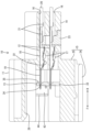
- FIG. 1 is a front view of the connector when the moving plate is in the initial position in Embodiment 1 of the present disclosure.
- FIG. 2 is a cross-sectional view taken along line AA of FIG.
- FIG. 3 is a side cross-sectional view of the connector in mated condition with a mating connector.
- FIG. 4 is a perspective view of the mating housing as seen obliquely from the front and above.
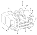
- FIG. 5 is a front view of the housing.
- FIG. 6 is a rear view of the housing.
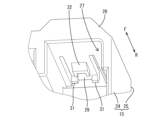
- FIG. 7 is a partially enlarged perspective view of the elastic locking portion as seen obliquely from the front and lower side.
- FIG. 8 is a perspective view of the moving plate as seen obliquely from the front and above.
- FIG. 9 is a perspective view of the moving plate as seen obliquely from the rear and above.
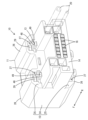
- FIG. 10 is a perspective view of the connector when the moving plate is in the mated position, as seen obliquely from the rear and above.
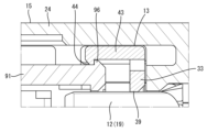
- FIG. 11 is a partially enlarged cross-sectional view showing a state in which the plate engaging portion of the mating housing is engaged with the engaging portion of the moving plate.
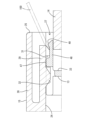
- FIG. 12 is a partially enlarged cross-sectional view showing a state in which the jig is hooked on the hook portion of the moving plate when the moving plate is in the initial position.
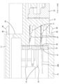
- FIG. 13 is a partially enlarged cross-sectional view showing a state in which the locking unlocking jig bends and deforms the lance when the moving plate is in the fitting position.
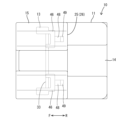
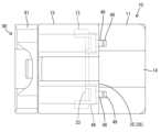
- FIG. 14 is a plan view of the connector when the moving plate is in its initial position.
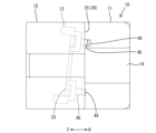
- FIG. 15 is a plan view of the connector when the moving plate is in the mating position.
- FIG. 16 is a plan view of the connector when the moving plate is tilted during the movement process.
- the connector of the present disclosure is (1) Between a housing having a receptacle, a male terminal having a tab protruding into the receptacle, and an initial position within the receptacle with respect to the housing and a fitting position behind the initial position.
- said moving plate having a plate body surrounding said tab of said male terminal within said receptacle; and a projecting portion projecting rearward from said plate body.
- the housing has a through hole through which the protrusion penetrates, and the protrusion is maintained in an unlocked state with respect to the housing at least in the fitting position, and extends rearwardly of the through hole. The rear end is exposed.
- the moving plate moves from the initial position to the fitting position, the amount of protrusion from the through-hole of the protrusion increases.
- the moving plate moves from the fitting position to the initial position, the amount of protrusion of the protrusion from the through hole decreases.
- the operator can detect the amount of movement of the moving plate from the fitting position by visually checking the amount of protrusion of the protrusion from the through hole, and furthermore, by visually checking the state (orientation) of the protrusion. , it is possible to detect whether the moving plate is tilted from the normal posture.
- the projecting portion is maintained in a non-locking state with respect to the housing, it is possible to prevent the projecting portion from interfering with the housing and bending deformation, etc., and the visibility of the projecting portion is excellent. As a result, it is possible to improve the reliability of detecting the state of the moving plate.
- the rear end portion of the projecting portion is arranged in the through hole at the initial position. According to the above configuration, it can be seen that the moving plate is not arranged at the initial position when the projecting portion is visible from the outside.
- the housing has a housing body that accommodates the male terminal behind the receptacle, and the rear end of the projecting portion is arranged along the outer surface of the housing body at the fitting position. It's good to be. According to the above configuration, the projecting portion is protected by the housing body, so breakage and damage can be avoided.
- a plurality of the protruding portions be formed side by side on the rear side of the plate body. According to the above configuration, even if the operator cannot visually recognize any one of the plurality of projecting portions, the operator can visually recognize the remaining projecting portions to determine the state of the moving plate. can be detected. In a situation where a worker can visually recognize a plurality of protrusions, the state of the moving plate can be detected with higher accuracy based on the positional relationship of each protrusion and the positional relationship between each protrusion and the housing.
- the projecting portion preferably has a hook portion projecting from the rear end portion of the projecting portion in a direction intersecting the front-rear direction.
- the moving plate When extracting the male terminal from the cavity of the housing, the moving plate may be previously moved from the initial position to the mating position.
- the projecting portion by hooking the jig on the hooking portion and pulling it backward, the projecting portion can be pulled out from the through hole, and the moving plate can be brought to the fitting position.
- the possibility of the jig interfering with the tab of the male terminal is low, and the tab may be broken or damaged. This can prevent situations where
- the housing has an elastic locking portion projecting rearward and capable of bending deformation. It is preferable to have locking projections for locking the plate body adjacently. According to the above configuration, by hooking the jig on the hook portion and pulling the jig backward, it is possible to efficiently transmit the force for releasing the locking with the plate body to the locking projection. Therefore, by pulling the jig backward, the elastic locking portion is flexurally deformed, and the locking between the locking projection and the plate main body can be released.
- the connector 10 includes a housing 11, male terminals 12 accommodated in the housing 11, and an initial position and a mating position with respect to the housing 11. and a moving plate 13 assembled movably therebetween.
- connector 10 is mated with mating connector 90 .
- the side where the connector 10 and the mating connector 90 are fitted to each other is defined as the front side. 2, 4, 7, etc.
- the side indicated by symbol F is the front side
- the side indicated by symbol R is the rear side.
- the vertical direction is based on the vertical direction in FIGS. 1 to 3.
- FIG. The vertical direction is synonymous with the height direction.
- the left-right direction is a direction intersecting the front-rear direction and the up-down direction, and is synonymous with the width direction.
- the mating connector 90 includes a mating housing 91 made of synthetic resin. As shown in FIGS. 3 and 4, the mating housing 91 has a plurality of mating cavities 92 . As shown in FIG. 3, each mating cavity 92 accommodates a female terminal 93 as a mating terminal.
- a flexibly deformable lock arm 94 is formed in the middle portion of the top surface of the mating housing 91 .
- the lock arm 94 has a role of locking the housing 11 and holding the housing 11 and the mating housing 91 in a fitted state. As shown in FIG. 4, a pair of release portions 95 are formed on both left and right sides of the front end portions of the upper and lower surfaces of the mating housing 91 so as to protrude therefrom.
- Each releasing portion 95 has a role of releasing the engagement between the moving plate 13 and the housing 11 at the initial position.
- Plate engaging portions 96 are formed on both left and right side surfaces of the mating housing 91 so as to protrude therefrom. Each plate engaging portion 96 is arranged in pairs in the height direction on the side surface of the mating housing 91 . Each plate engaging portion 96 has a role of moving the moving plate 13 from a fitting position, which will be described later, to an initial position.
- the housing 11 is made of synthetic resin and has a housing body 14 and a hood portion 15 projecting forward from the housing body 14 as shown in FIG. Housing body 14 has a plurality of cavities 16 . A lance 17 projecting forward is formed on the lower surface of the inner wall of each cavity 16 . Each cavity 16 accommodates a male terminal 12 .
- the male terminal 12 is made of a conductive metal, and as shown in FIG. and a barrel portion 21 connected to the The tab 19 protrudes into the hood portion 15 .
- the body portion 18 has a locking pawl 22 that is locked to the lance 17 within the cavity 16 .
- a rear end of the body portion 18 is locked by a retainer 23 assembled to the housing body 14 .
- the terminal fitting is primarily restricted from coming out of the cavity 16 by the lance 17 and secondarily restricted from coming out of the cavity 16 by the retainer 23 .
- the hood portion 15 has a tubular hood body 24 extending in the front-rear direction, and a stepped portion 25 extending upward and downward from the front end of the housing body 14 to the rear end of the hood body 24 . are doing.
- Each stepped portion 25 has a tunnel-shaped bulging portion 26 continuous from the hood main body 24 on both left and right sides, and has a pair of through holes 27 inside each bulging portion 26 .
- Each through-hole 27 extends in the front-rear direction through the stepped portion 25, is opened rearwardly of the stepped portion 25, and communicates with the inside of the hood body 24 as shown in FIG.
- the hood body 24 has a rectangular tubular shape, and has lock portions 28 protruding downward at the front ends of the left and right middle portions of the upper wall. As shown in FIG. 3, the lock portion 28 is locked to the lock arm 94. As shown in FIG. As shown in FIGS. 5, 7 and 12, the hood body 24 has a pair of elastic locking portions 29 (each of which is cantilevered) extending rearward from the front and rear intermediate portions of the left and right sides of the upper and lower walls. 7 and 12 show only one). As shown in FIGS. 7 and 12, the elastic locking portion 29 is arranged inside the through hole 27 . The elastic locking portion 29 has a locking projection 31 projecting inward (to the side where the housing body 14 is located) from the rear end portion.
- the locking projections 31 are arranged at the rear end portion of the elastic locking portion 29 with a space left and right.
- the front surface of the locking projection 31 is arranged vertically along the vertical direction.
- the rear surface of the locking projection 31 is inclined forward as it goes inward (toward the distal end in the projecting direction).
- the locking projection 31 has a role of restricting the movement of the moving plate 13 from the initial position to the fitting position.
- the elastic locking portion 29 has a main locking projection 32 protruding inward from the front-rear intermediate portion.
- the main locking projection 32 is arranged behind the locking projection 31 and between the left and right locking projections 31 in the left-right direction.
- the front surface of the final locking projection 32 is inclined backward as it goes inward.
- the rear surface of the main locking projection 32 is tilted forward as the left and right middle portions go inward, and both left and right end portions are arranged vertically along the up-down direction.
- the final locking projection 32 has a role of restricting the moving plate 13 from slipping forward from the hood portion 15 from the initial position.
- the moving plate 13 is made of synthetic resin, and includes a plate-like plate body 33, as shown in FIGS.
- the plate body 33 is arranged with its plate surface facing forward and backward.
- the plate body 33 has a plurality of positioning holes 34 in the left and right intermediate portions.
- Each positioning hole 34 has a rectangular cross section and penetrates the plate body 33 in the front-rear direction.
- a tab guiding portion 35 is formed at the opening edge of each positioning hole 34 so as to expand over the entire circumference.
- the tab 19 of the male terminal 12 is guided into the tab guiding portion 35 and inserted through the positioning hole 34 in a positioned state (see FIG. 2).
- the plate body 33 has a plurality of jig insertion holes 36 .
- Each jig insertion hole 36 has a rectangular cross-section and is arranged below each positioning hole 34 .
- a jig guiding portion 37 is formed at the opening edge of each jig insertion hole 36 so as to expand over the entire circumference.
- An unlocking jig 200 is inserted into the jig insertion hole 36 while being guided by the jig guide portion 37, and the tip thereof can come into contact with the lance 17 (see FIG. 13).
- the plate body 33 has a plurality of large-sized positioning holes 39 through which the tabs 19 of the large-sized male terminals 12 can be inserted, at both left and right ends of the positioning holes 34. ing.
- a large jig insertion hole 42 for unlocking the large lance 17 is formed below each large positioning hole 39 .
- Each large positioning hole 39 communicates with each large jig insertion hole 42 .
- the moving plate 13 has a pair of engaging portions 43 projecting forward from the upper and lower middle portions of the left and right ends of the plate body 33 .
- Each engaging portion 43 has a rectangular plate shape and is arranged with its plate surface directed to the left and right.
- an engaging protrusion 44 is formed that protrudes inward (on the side facing each other).
- the engaging protrusion 44 extends vertically in the form of a rib at the front end of the engaging portion 43 .
- the engaging protrusion 44 of the engaging portion 43 can be engaged with the plate engaging portion 96 of the mating housing 91 in a hooked state.
- the moving plate 13 has a plurality of guide parts 45 projecting forward from the four corners of the plate body 33, as shown in FIG.
- Each guide portion 45 has an L-shaped cross section and is formed over two sides that respectively partition the four corners of the plate body 33 .
- Each guide portion 45 slides on the inner surface of the four corners of the hood body 24 and serves to guide the movement of the moving plate 13 within the hood portion 15 (see FIG. 1).
- the moving plate 13 has a pair of frame portions 46 projecting rearward from both left and right sides of the upper and lower ends of the plate body 33. As shown in FIG. Each frame portion 46 has a rectangular frame shape in a plan view, and has a beam-like engaged portion 47 along the width direction at the rear end portion.
- the moving plate 13 has a pair of protruding portions 48 that protrude rearward from the left and right intermediate portions of the engaged portion 47 of each frame portion 46 .
- Each projecting portion 48 has a rectangular plate shape in a plan view, and is arranged with the plate surface facing up and down.
- Each protruding portion 48 has a hook portion 49 protruding outward (vertically separated side) at its rear end portion.
- the hook portion 49 has a rib-like shape extending in the left-right direction at the rear end portion of the projecting portion 48 .
- the front surface of the hook portion 49 is inclined rearward toward the outside (the tip side in the projecting direction).
- a rear surface of the hook portion 49 is inclined forward toward the outside.
- the moving plate 13 Prior to fitting the housing 11 and the mating housing 91 together, the moving plate 13 is assembled in the hood portion 15 of the housing 11 and held in the initial position with respect to the housing 11 .
- the plate body 33 In the initial position, the plate body 33 is arranged inside the hood portion 15 , and the front ends of the tabs 19 of the male terminals 12 are inserted through the positioning holes 34 of the plate body 33 .
- the locked portion 47 of the moving plate 13 is sandwiched between the locking projections 31 and the main locking projections 32 of the elastic locking portion 29 in the front-to-rear direction. Movement of the moving plate 13 within 15 is restricted.
- the projections 48 are located within each through-hole 27 of the housing 11, including a catch 49 at the rear end. Therefore, as shown in FIG. 14, even when the housing 11 is viewed from above, the projecting portions 48 are hidden in the receptacle 15 and cannot be visually recognized.
- the mating housing 91 is inserted into the receptacle 15 at the start of mating of the housing 11 and the mating housing 91 . Then, each releasing portion 95 of the mating housing 91 slides on the front surface of the final locking projection 32 of each elastic locking portion 29 (the front surface when viewed from the connector 10 side), and each elastic locking portion 29 is flexurally deformed outward. and the locking between each locking projection 31 and each locked portion 47 is released. As a result, the moving plate 13 becomes movable. As the mating of the connector 10 progresses, the moving plate 13 is pressed against the mating housing 91 and moved toward the mating position.
- the moving plate 13 can reach the fitting position.
- the plate body 33 is sandwiched between the housing body 14 and the mating housing 91 at the rear end side (rear end side) of the receptacle 15 .
- Each male terminal 12 is electrically connected to each female terminal 93 accommodated in the mating housing 91 .
- the lock arm 94 is elastically locked to the lock portion 28, and the housing 11 and the mating housing 91 are held in a fitted state.
- each protruding part 48 protrudes rearward from each through hole 27 and is exposed on the outer surface of the housing main body 14 .
- each projecting portion 48 is arranged along the upper and lower surfaces of the housing body 14 with a slight gap therebetween (see FIG. 13). That is, each projecting portion 48 is arranged on the outer surface of the housing body 14 in a non-contact state.
- the amount of protrusion (the amount of exposure) of each protrusion 48 from each through hole 27 gradually increases as the moving plate 13 approaches the fitting position.
- the amount of projection of each projection 48 from each through hole 27 is the maximum value, and the entire hooking portion 49 of each projection 48 is exposed on the outer surface of the housing body 14 (FIG. 10). and FIG. 15).
- the two protrusions 48 are arranged on the upper surface of the housing body 14 . Therefore, when the connector 10 is viewed from above in the normal line of sight of the operator, the state (orientation) of the two protrusions 48 arranged on the upper surface of the housing body 14 can be easily adjusted as shown in FIG. can be visually recognized. In particular, since each projecting portion 48 has a rectangular shape in plan view and does not have a complicated shape, the visibility is excellent.
- the amount of projection of the projecting portion 48 from the through hole 27 has not reached the maximum value, it can be seen that the moving plate 13 has not yet reached the fitting position. In the case of Embodiment 1, when the moving plate 13 is assembled to the housing 11 in a normal posture, as shown in FIG. and intersect at right angles.
- the tabs 19 of the male terminals 12 would interfere with the hole surfaces of the positioning holes 34 of the plate body 33. do not have.
- the protrusions 48 are also tilted according to the tilt, and the two protrusions exposed on the upper surface of the housing body 14 are formed.
- the tilted state of the portion 48 can be visually recognized from above the housing 11 .
- the two protruding portions 48 each take an inclined posture with respect to the front-rear direction.
- one of the two projecting portions 48 projects largely rearward from the rear surface of the stepped portion 25 , while the other projecting portion 48 projects slightly from the rear surface of the stepped portion 25 or inside the stepped portion 25 . (inside the through hole 27). Therefore, it can be seen that the moving plate 13 is in a tilted state by visually recognizing the above state of each projecting portion 48 .
- the moving plate 10 is positioned at the initial position in consideration of the operability of the jig 200 for unlocking. It is desired to move 13 to the mated position.
- the tip of the jig 100 is inserted into the through hole 27 and hooked on the hook portion 49 of the projecting portion 48, and in this state, the jig 100 is pulled backward.
- the moving plate 13 can be moved toward the fitting position.
- the locking projection 31 is adjacent to the front of the hooking portion 49 of the projecting portion 48, so that the pulling force of the jig 100 can be directly transmitted to the locking projection 31. can. Therefore, the locking between the locking protrusion 31 and the plate body 33 can be easily released according to the retreat of the plate body 33 . Thereby, the moving plate 13 can be brought to the fitting position.
- the unlocking jig 200 is inserted through the jig insertion hole 36 of the plate body 33 , and the tip of the jig 200 is inserted into the lance 17 .
- the lock of the lance 17 with respect to the locking claw 22 of the male terminal 12 can be released.
- the male terminal 12 can be pulled out from the cavity 16 by pulling the wire 20 rearward while the lock of the lance 17 is released.
- the operator can detect the amount of movement of the moving plate 13 from the fitting position by visually checking the amount of protrusion of the protrusion 48 from the through hole 27 . can. Also, by visually checking the state (orientation) of each protrusion 48, the positional relationship between each protrusion 48, and the positional relationship between each protrusion 48 and the housing 11, it is possible to detect whether or not the moving plate 13 is tilted. be able to.
- the projecting portion 48 is maintained in a non-locked state with respect to the housing 11 and does not interfere with the housing 11.
- the projecting portion 48 itself is a simple band-shaped plate. Because of its shape, it has excellent visibility. As a result, the reliability of detecting the state of the moving plate 13 can be improved.
- each projecting portion 48 since the hook portion 49 (rear end portion) of each projecting portion 48 is arranged in the through hole 27 at the initial position, the moving plate 13 may be moved to the initial position when the projecting portion 48 is exposed to the outside. It can be seen that it is not placed in
- each projecting portion 48 is arranged along the outer surface of the housing body 14 at the fitting position, the projecting portion 48 is protected by the housing body 14 to avoid breakage or damage. be able to.
- the two projecting portions 48 are arranged side by side on the upper surface of the housing body 14 with a space therebetween, moving can be performed based on the positional relationship between each projecting portion 48 and the positional relationship between each projecting portion 48 and the housing 11 .
- the state of the plate 13 can be detected with higher accuracy. Further, even if one of the two protrusions 48 cannot be visually recognized, the state of the moving plate 13 can be detected by looking at the other protrusion 48 .
- the protrusion 48 can be pulled out from the through hole 27 by hooking the jig 100 on the hook 49 of the protrusion 48 and pulling it backward. , the moving plate 13 can be brought to the fitting position. This reduces the possibility that the jig 100 interferes with the tab 19 of the male terminal 12, unlike the case where the jig 100 presses the plate body 33 from the front to bring the moving plate 13 to the fitting position. Therefore, it is possible to prevent the tab 19 from being broken or damaged.
- Embodiment 1 disclosed this time is illustrative in all respects and is not restrictive.
- a plurality of projections are provided on the moving plate.
- only one protrusion may be provided on the moving plate. Considering visibility, it is desirable that this one protrusion be exposed on the upper surface of the housing body at least at the mating position.
- the rear end portion of the projecting portion was arranged in the through hole at the initial position.
- the rear end of the protrusion may be exposed rearward from the through hole at the initial position.
- the rear end portion of the projecting portion is exposed outside from the through-hole at the initial stage of fitting from the initial position to the fitting position.
- the rear end portion of the protrusion may be exposed outside from the through hole immediately before reaching the fitting position.
- the projecting portion has a hook portion at the rear end portion.
- the protrusion may not have a hook.
- the projecting portion may be a simple flat plate without irregularities.
- the projecting portion when the moving plate moves between the initial position and the fitting position, the projecting portion is arranged in a non-contact state with the outer surface (upper surface and lower surface) of the housing body.
- the protrusion may contact the outer surface of the housing body in an unlocked state.
Landscapes
- Details Of Connecting Devices For Male And Female Coupling (AREA)
Abstract
Description
最初に本開示の実施態様を列記して説明する。
本開示のコネクタは、
(1)フード部を有するハウジングと、前記フード部内に突出するタブを有する雄端子と、前記ハウジングに対し、前記フード部内における初期位置と、前記初期位置よりも後方の嵌合位置と、の間を移動可能に配置されるムービングプレートと、を備え、前記ムービングプレートは、前記フード部内で前記雄端子の前記タブを包囲するプレート本体と、前記プレート本体より後方に突出する突出部と、を有し、前記ハウジングは、前記突出部が貫通する貫通孔を有し、前記突出部は、少なくとも前記嵌合位置において、前記ハウジングに対して非係止の状態に維持され、前記貫通孔の後方に後端部を露出させている。
上記構成によれば、突出部が外側から見える状態では、ムービングプレートが初期位置に配置されていないことがわかる。
上記構成によれば、突出部は、ハウジング本体によって保護されるので、折損、破損される事態を回避することができる。
上記構成によれば、仮に、作業者が、複数の突出部のうち、いずれか1つの突出部を視認できない状況下であっても、残りの突出部を視認することにより、ムービングプレートの状態を検知することができる。作業者が、複数の突出部を視認できる状況下においては、各突出部の位置関係や各突出部とハウジングとの位置関係に基づいて、ムービングプレートの状態をより精度良く検知することができる。
雄端子をハウジングのキャビティ内から抜き取る際に、前もってムービングプレートを初期位置から嵌合位置に移動させることがある。上記構成によれば、引掛部に治具を引っ掛けて後方に引っ張ることにより、突出部を貫通孔から引き出すことができ、ムービングプレートを嵌合位置に至らすことができる。プレート本体を前方から治具で押圧してムービングプレートを嵌合位置に至らす場合と異なり、上記構成の場合、雄端子のタブに治具が干渉する可能性が低く、タブが折損、破損される事態を防止できる。
上記構成によれば、引掛部に治具を引っ掛け、治具を後方に引っ張ることにより、係止突起に、プレート本体との係止を解除させる力を効率良く伝達することができる。このため、治具を後方に引っ張ることにより、弾性係止部を撓み変形させ、係止突起とプレート本体との係止を解除することができる。
本開示の具体例を、以下に図面を参照しつつ説明する。なお、本発明はこの例示に限定されるものではなく、請求の範囲によって示され、請求の範囲と均等の意味および範囲内でのすべての変更が含まれることが意図される。
本開示の実施形態1に係るコネクタ10は、図1および図2に示すように、ハウジング11と、ハウジング11に収容される雄端子12と、ハウジング11に対して初期位置と嵌合位置との間を移動可能に組み付けられるムービングプレート13と、を備える。図3に示すように、コネクタ10は、相手コネクタ90と嵌合される。なお、以下の説明において、前後方向については、コネクタ10と相手コネクタ90とが互いに嵌合される側を前側とする。図2、図4および図7等において、符号Fで示す側が前側で、符号Rで示す側が後側である。上下方向は、図1~図3の上下方向を基準とする。上下方向は、高さ方向と同義である。左右方向は、前後方向および上下方向と交差する方向であり、幅方向と同義である。
相手コネクタ90は、合成樹脂製の相手ハウジング91を備える。図3および図4に示すように、相手ハウジング91は、複数の相手キャビティ92を有している。図3に示すように、各相手キャビティ92には、相手端子としての雌端子93が収容されている。相手ハウジング91の上面の左右中間部には、撓み変形可能なロックアーム94が形成されている。ロックアーム94は、ハウジング11を係止し、ハウジング11と相手ハウジング91とを嵌合状態に保持する役割を有している。図4に示すように、相手ハウジング91の上面および下面の前端部における左右両側には、一対ずつの解除部95が突出して形成されている。各解除部95は、初期位置にあるムービングプレート13とハウジング11との係止を解除する役割を有している。また、相手ハウジング91の左右両側の側面には、それぞれプレート係合部96が突出して形成されている。各プレート係合部96は、相手ハウジング91の側面に高さ方向に対をなして配置されている。各プレート係合部96は、ムービングプレート13を後述する嵌合位置から初期位置に移動させる役割を有している。
ハウジング11は合成樹脂製であって、図2に示すように、ハウジング本体14と、ハウジング本体14から前方に突出するフード部15と、を有している。ハウジング本体14は、複数のキャビティ16を有している。各キャビティ16の内壁下面には、前方に突出するランス17が形成されている。各キャビティ16には、雄端子12が収容されている。
ハウジング11および相手ハウジング91の嵌合に先立ち、ハウジング11のフード部15内にムービングプレート13が組み込まれ、ハウジング11に対してムービングプレート13が初期位置に保持される。図2に示すように、初期位置において、プレート本体33がフード部15内に配置され、各雄端子12のタブ19の前端部がプレート本体33の各位置決め孔34に挿通される。また、図12に示すように、初期位置では、ムービングプレート13の被係止部47が弾性係止部29における係止突起31と本係止突起32との間に前後に挟まれ、フード部15内におけるムービングプレート13の移動が規制される。さらに、初期位置において、突出部48は、後端部における引掛部49を含め、ハウジング11の各貫通孔27内に配置される。このため、図14に示すように、ハウジング11を上方から見ても、各突出部48はフード部15内に隠れて視認できない状態になっている。
今回開示された実施形態1はすべての点で例示であって制限的なものではないと考えるべきである。
上記実施形態1の場合、突出部は、ムービングプレートに複数設けられていた。しかし、他の実施形態として、突出部は、ムービングプレートに1つ設けられるだけでも良い。この1つの突出部は、視認性を考慮し、少なくとも嵌合位置でハウジング本体の上面上に露出するのが望ましい。
上記実施形態1の場合、突出部の後端部は、初期位置で貫通孔内に配置されていた。しかし、他の実施形態として、突出部の後端部は、初期位置で貫通孔から後方に露出するものであっても良い。
上記実施形態1の場合、突出部の後端部は、初期位置から嵌合位置に向かう嵌合初期の段階で貫通孔から外側に露出していた。しかし、他の実施形態として、突出部の後端部は、嵌合位置に至る直前に貫通孔から外側に露出するものであっても良い。
上記実施形態1の場合、突出部は、後端部に引掛部を有していた。しかし、他の実施形態として、突出部は、引掛部を有していなくても良い。例えば、突出部は、凹凸の無い単なる平板であっても良い。
上記実施形態1の場合、ムービングプレートが初期位置と嵌合位置との間を移動する際、突出部は、ハウジング本体の外面(上面および下面)に非接触状態で配置されていた。しかし、他の実施形態として、ムービングプレートが初期位置と嵌合位置との間を移動する際、突出部は、ハウジング本体の外面に非係止状態であるが接触していても良い。
11…ハウジング
12…雄端子
13…ムービングプレート
14…ハウジング本体
15…フード部
16…キャビティ
17…ランス
18…本体部
19…タブ
20…電線
21…バレル部
22…係止爪
23…リテーナ
24…フード本体
25…段部
26…膨出部
27…貫通孔
28…ロック部
29…弾性係止部
31…係止突起
32…本係止突起
33…プレート本体
34…位置決め孔
35…タブ誘い込み部
36…治具挿通孔
37…治具誘い込み部
39…大型位置決め孔
42…大型治具挿通孔
43…係合部
44…係合突起
45…ガイド部
46…枠部
47…被係止部
48…突出部
49…引掛部
90…相手コネクタ
91…相手ハウジング
92…相手キャビティ
93…雌端子
94…ロックアーム
95…解除部
96…プレート係合部
100…治具
200…係止解除用の治具
Claims (6)
- フード部を有するハウジングと、
前記フード部内に突出するタブを有する雄端子と、
前記ハウジングに対し、前記フード部内における初期位置と、前記初期位置よりも後方の嵌合位置と、の間を移動可能に配置されるムービングプレートと、を備え、
前記ムービングプレートは、前記フード部内で前記雄端子の前記タブを包囲するプレート本体と、前記プレート本体より後方に突出する突出部と、を有し、
前記ハウジングは、前記突出部が貫通する貫通孔を有し、
前記突出部は、少なくとも前記嵌合位置において、前記ハウジングに対して非係止の状態に維持され、前記貫通孔の後方に後端部を露出させている、コネクタ。 - 前記突出部の後端部は、前記初期位置で前記貫通孔内に配置されている、請求項1に記載のコネクタ。
- 前記ハウジングは、前記フード部の後方に、前記雄端子を収容するハウジング本体を有し、前記突出部の後端部は、前記嵌合位置で前記ハウジング本体の外面上に沿って配置されている、請求項1又は請求項2に記載のコネクタ。
- 前記突出部は、前記プレート本体の後方に複数並んで形成されている、請求項1から請求項3のいずれか一項に記載のコネクタ。
- 前記突出部は、前記突出部の後端部から前後方向と交差する方向に突出する引掛部を有している、請求項1から請求項4のいずれか一項に記載のコネクタ。
- 前記ハウジングは、後方に突出する撓み変形可能な弾性係止部を有し、
前記弾性係止部の後端部は、前記ムービングプレートが前記初期位置にあるときに、前記引掛部に隣接して前記プレート本体を係止する係止突起を有している、請求項5に記載のコネクタ。
Priority Applications (2)
| Application Number | Priority Date | Filing Date | Title |
|---|---|---|---|
| US18/837,890 US20250149829A1 (en) | 2022-02-14 | 2023-01-30 | Connector |
| CN202380019286.5A CN118648197A (zh) | 2022-02-14 | 2023-01-30 | 连接器 |
Applications Claiming Priority (2)
| Application Number | Priority Date | Filing Date | Title |
|---|---|---|---|
| JP2022020221A JP7582226B2 (ja) | 2022-02-14 | 2022-02-14 | コネクタ |
| JP2022-020221 | 2022-02-14 |
Publications (1)
| Publication Number | Publication Date |
|---|---|
| WO2023153258A1 true WO2023153258A1 (ja) | 2023-08-17 |
Family
ID=87564208
Family Applications (1)
| Application Number | Title | Priority Date | Filing Date |
|---|---|---|---|
| PCT/JP2023/002851 Ceased WO2023153258A1 (ja) | 2022-02-14 | 2023-01-30 | コネクタ |
Country Status (4)
| Country | Link |
|---|---|
| US (1) | US20250149829A1 (ja) |
| JP (1) | JP7582226B2 (ja) |
| CN (1) | CN118648197A (ja) |
| WO (1) | WO2023153258A1 (ja) |
Citations (7)
| Publication number | Priority date | Publication date | Assignee | Title |
|---|---|---|---|---|
| JP2011080795A (ja) * | 2009-10-05 | 2011-04-21 | Yazaki Corp | コネクタ検査装置 |
| JP2011086478A (ja) * | 2009-10-15 | 2011-04-28 | Tyco Electronics Japan Kk | 電気コネクタ組立体 |
| JP2016046085A (ja) * | 2014-08-22 | 2016-04-04 | 矢崎総業株式会社 | コネクタ |
| JP2019212404A (ja) * | 2018-06-01 | 2019-12-12 | 住友電装株式会社 | コネクタ |
| JP2021157975A (ja) * | 2020-03-27 | 2021-10-07 | 住友電装株式会社 | コネクタ |
| JP2021157971A (ja) * | 2020-03-27 | 2021-10-07 | 住友電装株式会社 | コネクタ |
| KR102338388B1 (ko) * | 2020-07-03 | 2021-12-10 | 주식회사 경신 | 방수커넥터 |
-
2022
- 2022-02-14 JP JP2022020221A patent/JP7582226B2/ja active Active
-
2023
- 2023-01-30 CN CN202380019286.5A patent/CN118648197A/zh active Pending
- 2023-01-30 US US18/837,890 patent/US20250149829A1/en active Pending
- 2023-01-30 WO PCT/JP2023/002851 patent/WO2023153258A1/ja not_active Ceased
Patent Citations (7)
| Publication number | Priority date | Publication date | Assignee | Title |
|---|---|---|---|---|
| JP2011080795A (ja) * | 2009-10-05 | 2011-04-21 | Yazaki Corp | コネクタ検査装置 |
| JP2011086478A (ja) * | 2009-10-15 | 2011-04-28 | Tyco Electronics Japan Kk | 電気コネクタ組立体 |
| JP2016046085A (ja) * | 2014-08-22 | 2016-04-04 | 矢崎総業株式会社 | コネクタ |
| JP2019212404A (ja) * | 2018-06-01 | 2019-12-12 | 住友電装株式会社 | コネクタ |
| JP2021157975A (ja) * | 2020-03-27 | 2021-10-07 | 住友電装株式会社 | コネクタ |
| JP2021157971A (ja) * | 2020-03-27 | 2021-10-07 | 住友電装株式会社 | コネクタ |
| KR102338388B1 (ko) * | 2020-07-03 | 2021-12-10 | 주식회사 경신 | 방수커넥터 |
Also Published As
| Publication number | Publication date |
|---|---|
| JP7582226B2 (ja) | 2024-11-13 |
| CN118648197A (zh) | 2024-09-13 |
| US20250149829A1 (en) | 2025-05-08 |
| JP2023117578A (ja) | 2023-08-24 |
Similar Documents
| Publication | Publication Date | Title |
|---|---|---|
| JP7251398B2 (ja) | コネクタ | |
| JP3800312B2 (ja) | コネクタ | |
| EP2249440B1 (en) | A connector, connector assembly and connection method | |
| JP3991911B2 (ja) | コネクタ | |
| JP4267935B2 (ja) | 電気コネクタ組立体及び電気コネクタ | |
| JP2007080621A (ja) | コネクタ | |
| CN110571568B (zh) | 连接器 | |
| JP6569131B2 (ja) | 嵌合検知機能を有する電気接続装置 | |
| JPH10172672A (ja) | コネクタ | |
| JP7042402B2 (ja) | コネクタ | |
| US7267569B2 (en) | Connector with a shorting terminal | |
| CN1332479C (zh) | 一种分离式连接器以及一种使辅助连接器外壳从其中脱离的方法 | |
| JP2546579Y2 (ja) | コネクタ | |
| JP3427782B2 (ja) | コネクタ | |
| WO2023153258A1 (ja) | コネクタ | |
| JP7640516B2 (ja) | コネクタ、及び、コネクタにおける端子抜き方法 | |
| CN112152015A (zh) | 连接器 | |
| JP4725500B2 (ja) | コネクタ | |
| JP3598990B2 (ja) | コネクタ | |
| JP6828835B2 (ja) | コネクタ | |
| JP5212284B2 (ja) | コネクタ | |
| JP4089168B2 (ja) | コネクタ | |
| CN219892487U (zh) | 电连接器和电连接器组件 | |
| JP2024080961A (ja) | コネクタ、及び、コネクタにおける端子抜き方法 | |
| JP2023131383A (ja) | コネクタ |
Legal Events
| Date | Code | Title | Description |
|---|---|---|---|
| 121 | Ep: the epo has been informed by wipo that ep was designated in this application |
Ref document number: 23752723 Country of ref document: EP Kind code of ref document: A1 |
|
| WWE | Wipo information: entry into national phase |
Ref document number: 202380019286.5 Country of ref document: CN |
|
| WWE | Wipo information: entry into national phase |
Ref document number: 18837890 Country of ref document: US |
|
| NENP | Non-entry into the national phase |
Ref country code: DE |
|
| 122 | Ep: pct application non-entry in european phase |
Ref document number: 23752723 Country of ref document: EP Kind code of ref document: A1 |
|
| WWP | Wipo information: published in national office |
Ref document number: 18837890 Country of ref document: US |