WO2023149452A1 - Procédé de soudage au laser - Google Patents
Procédé de soudage au laser Download PDFInfo
- Publication number
- WO2023149452A1 WO2023149452A1 PCT/JP2023/003156 JP2023003156W WO2023149452A1 WO 2023149452 A1 WO2023149452 A1 WO 2023149452A1 JP 2023003156 W JP2023003156 W JP 2023003156W WO 2023149452 A1 WO2023149452 A1 WO 2023149452A1
- Authority
- WO
- WIPO (PCT)
- Prior art keywords
- laser
- laser beam
- core
- laser light
- emitted
- Prior art date
Links
Images


Classifications
-
- B—PERFORMING OPERATIONS; TRANSPORTING
- B23—MACHINE TOOLS; METAL-WORKING NOT OTHERWISE PROVIDED FOR
- B23K—SOLDERING OR UNSOLDERING; WELDING; CLADDING OR PLATING BY SOLDERING OR WELDING; CUTTING BY APPLYING HEAT LOCALLY, e.g. FLAME CUTTING; WORKING BY LASER BEAM
- B23K26/00—Working by laser beam, e.g. welding, cutting or boring
- B23K26/02—Positioning or observing the workpiece, e.g. with respect to the point of impact; Aligning, aiming or focusing the laser beam
- B23K26/06—Shaping the laser beam, e.g. by masks or multi-focusing
- B23K26/064—Shaping the laser beam, e.g. by masks or multi-focusing by means of optical elements, e.g. lenses, mirrors or prisms
-
- B—PERFORMING OPERATIONS; TRANSPORTING
- B23—MACHINE TOOLS; METAL-WORKING NOT OTHERWISE PROVIDED FOR
- B23K—SOLDERING OR UNSOLDERING; WELDING; CLADDING OR PLATING BY SOLDERING OR WELDING; CUTTING BY APPLYING HEAT LOCALLY, e.g. FLAME CUTTING; WORKING BY LASER BEAM
- B23K26/00—Working by laser beam, e.g. welding, cutting or boring
- B23K26/02—Positioning or observing the workpiece, e.g. with respect to the point of impact; Aligning, aiming or focusing the laser beam
- B23K26/06—Shaping the laser beam, e.g. by masks or multi-focusing
- B23K26/073—Shaping the laser spot
-
- B—PERFORMING OPERATIONS; TRANSPORTING
- B23—MACHINE TOOLS; METAL-WORKING NOT OTHERWISE PROVIDED FOR
- B23K—SOLDERING OR UNSOLDERING; WELDING; CLADDING OR PLATING BY SOLDERING OR WELDING; CUTTING BY APPLYING HEAT LOCALLY, e.g. FLAME CUTTING; WORKING BY LASER BEAM
- B23K26/00—Working by laser beam, e.g. welding, cutting or boring
- B23K26/20—Bonding
- B23K26/21—Bonding by welding
Definitions
- the present invention relates to a laser welding method.
- Patent Literature 1 discloses a laser welding joint structure in which two busbars are provided with projections, and the two projections are irradiated with a laser to melt the projections and join the busbars together. ing.
- the heat capacity of the protrusion with a small cross-sectional area is smaller than that of the protrusion with a large cross-sectional area. Therefore, when a laser beam is emitted to two protrusions, the protrusion having a small heat capacity melts down first, resulting in variation in the shape and bonding strength of the joint.
- the present invention has been made in view of this point, and its object is to suppress variations in the bonding strength between the first member and the second member having different heat capacities.
- a first aspect is a laser welding method of emitting a laser beam transmitted through a transmission fiber to weld a first member and a second member having a smaller heat capacity than the first member, wherein the transmission fiber has a first core and a second core provided on the outer periphery of the first core, and a first laser beam is emitted from either the first core or the second core to the first member and a second laser having a lower output than the first laser light from the other of the first core and the second core to the second member during the execution of the first step and a second step of emitting light.
- the transmission fiber has a first core and a second core.
- the second core is provided on the outer periphery of the first core.
- a first laser beam is emitted from one of the first core and the second core to the first member.
- the second laser beam is emitted from the other of the first core and the second core to the second member during execution of the first step.
- the second member has a smaller heat capacity than the first member.
- the second laser light has a lower output than the first laser light.
- the melting timing of the first member and the second member can be matched to prevent the second member, which has a small heat capacity, from being melted down first.
- the joint shape of the first member and the second member is stabilized, variations in joint strength can be suppressed.
- the first step and the second step by changing the ratio of the laser light incident on the first core and the second core, the first It is characterized by changing the outputs of the laser light and the second laser light.
- the outputs of the first laser light and the second laser light are changed. be able to.
- the first laser beam is emitted from the first core
- the second laser beam is emitted from the second core. is emitted.
- a high-power first laser beam can be emitted from the circular first core, and a low-power second laser beam can be emitted from the ring-shaped second core.
- the first laser beam is emitted from the second core
- the second laser beam is emitted from the first core. is emitted.
- a high-power first laser beam can be emitted from the ring-shaped second core, and a low-power second laser beam can be emitted from the circular first core.
- the laser beam is emitted to each of the first member and the second member, It is characterized by comprising a step of preheating the first member and the second member.
- preheating the first member and the second member makes it easier to melt the first member and the second member in the first step and the second step.
- a sixth aspect is any one of the first to fifth aspects, wherein, before the first step, the spot diameter of the laser beam at the welded portion of the first member and the second member is adjusted. It is characterized by comprising steps.
- the laser beam is emitted to the entire range of the welding points. can be done.
- a seventh aspect is characterized in that, in any one of the first to sixth aspects, the first laser light and the second laser light have different wavelengths.
- the highly reflective material when the first member or the second member is made of a highly reflective material, the highly reflective material is easily melted by emitting a laser beam having a wavelength that is easily absorbed by the highly reflective material. .
- At least one of the first laser beam and the second laser beam is emitted during the execution of the first step and the second step. It is characterized by comprising a step of adjusting the output.
- FIG. 1 is a side view showing a schematic configuration of a laser welding apparatus according to Embodiment 1.
- FIG. FIG. 2 is a cross-sectional view of the transmission fiber viewed from the incident end side.
- FIG. 3A is a diagram showing incident positions of laser light with respect to transmission fibers.
- FIG. 3B is a diagram showing a beam profile of laser light emitted from a transmission fiber.
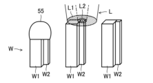
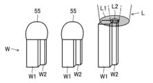
- FIG. 4A is a diagram showing a state in which a first circular laser beam is emitted to a first member and a second ring-shaped laser beam is emitted to a second member.
- FIG. 4B is a diagram illustrating a state in which the first member and the second member are joined;
- FIG. 4C is a diagram for comparing the shapes of joints.
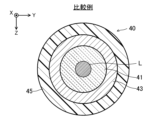
- FIG. 5A is a diagram showing incident positions of laser light with respect to a transmission fiber as a comparative example.
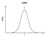
- FIG. 5B is a diagram showing a beam profile of laser light as a comparative example.
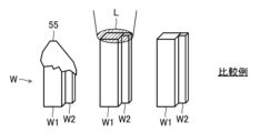
- FIG. 6A is a diagram showing a state in which one laser beam is emitted to the first member and the second member;
- FIG. 6B is a diagram showing a state in which the first member and the second member are joined;
- FIG. 6C is a diagram for comparing the shapes of joints.
- FIG. 7A is a diagram showing the incident position of the laser beam with respect to the transmission fiber in the laser welding device according to Embodiment 2.
- FIG. FIG. 7B is a diagram showing a beam profile of laser light emitted from a transmission fiber.
- FIG. 8A is a diagram showing a state in which a first ring-shaped laser beam is emitted to a first member and a second circular laser beam is emitted to a second member.
- FIG. 8B is a diagram showing a state in which the first member and the second member are joined;
- FIG. 8C is a diagram for comparing the shapes of joints.
- FIG. 9 is a diagram showing the configuration of an optical coupling unit in a laser welding device according to this modification.
- FIG. 10 is a diagram showing a state in which the incident position of laser light is changed.
- the laser welding apparatus 1 includes a laser oscillator 10, an optical coupling unit 20, a focusing unit 30, a transmission fiber 40, a laser processing head 50, a stage 60, and a manipulator 65. .
- the traveling direction of the laser beam L emitted from the laser processing head 50 to the workpiece W is called the Z direction.
- the traveling direction of the laser light L traveling from the optical coupling unit 20 to the condensing unit 30 is called the X direction.
- a direction that crosses the X direction and the Y direction is called the Y direction.
- the laser oscillator 10 has multiple laser modules 11 and a laser beam combiner 12 .
- the laser module 11 emits a laser beam L.
- the laser beam synthesizer 12 synthesizes the laser beams L emitted from the plurality of laser modules 11 and emits them as one laser beam L. As shown in FIG.
- the wavelength of the laser light L is in the range of 900 nm to 1000 nm, but it is not particularly limited to this, and can take other values as appropriate.
- the optical coupling unit 20 has a housing 21 , a folding mirror 22 and an optical path changing mechanism 23 .
- the folding mirror 22 is arranged inside the housing 21 .
- the folding mirror 22 reflects the laser beam L emitted from the laser oscillator 10 toward the optical path changing mechanism 23 .
- the laser oscillator 10 is arranged inside the housing 21 in the example shown in FIG. 1 , it may be arranged outside the housing 21 .
- the optical path changing mechanism 23 has a mirror 24 , a piezo stage 25 and a piezo actuator 26 .
- the mirror 24 reflects the laser light L reflected by the folding mirror 22 toward the condenser lens 32 of the condenser unit 30 .
- the mirror 24 is integrally attached to the piezo actuator 26.
- a piezo actuator 26 is attached to the piezo stage 25 .
- the mirror 24 is tilted around an axis parallel to the Y direction by driving the piezo actuator 26 .
- the mirror 24 changes the optical axis of the laser light L within a predetermined range.
- the folding mirror 22 may be omitted.
- the optical path changing mechanism 23 may be configured to be able to adjust the emission position of the laser light L with respect to the condenser lens 32 in two axial directions (the X direction and the Y direction in FIG. 1). In this case, the configuration may be such that the mirror 24 is moved in two axial directions by the piezoelectric actuator 26 .
- the condensing unit 30 has a housing 31 , a condensing lens 32 , a shutter 33 and a beam damper 34 .
- the condenser lens 32 is arranged inside the housing 31 .
- the condenser lens 32 collects the laser light L reflected by the mirror 24 of the optical path changing mechanism 23 and makes it enter the transmission fiber 40 .
- the condensing unit 30 In order to align the condensing position of the laser light L with the incident end surface of the transmission fiber 40, the condensing unit 30 is provided with a condensing position adjustment section (not shown).
- the condenser lens 32 is moved along the optical path of the laser light L by the condenser position adjusting section.
- the shutter 33 is configured to be movable between the inside of the optical path of the laser beam L and the outside of the optical path.
- the shutter 33 opens and closes the optical path of the laser light L according to a predetermined control signal.
- the shutter 33 is arranged in the optical path of the laser light L, the laser light L reflected by the shutter 33 enters the beam damper 34 and is converted into heat.
- the transmission fiber 40 is connected to the condensing unit 30 and the laser processing head 50 .
- the transmission fiber 40 transmits the laser beam L incident from the light collecting unit 30 to the laser processing head 50 .
- the structure of the transmission fiber 40 will be described later.
- the laser processing head 50 emits the laser beam L incident from the transmission fiber 40 to the work W.
- the laser processing head 50 has a collimation lens 51 , a condenser lens 52 and a protective glass 53 .
- the collimation lens 51 collimates the laser light L emitted from the emission end of the transmission fiber 40 .
- the condenser lens 52 collects the laser light L collimated by the collimation lens 51 .
- the laser beam L condensed by the condensing lens 52 is emitted to the work W, and the work W is laser-welded.
- the laser processing head 50 is provided with a condensing position adjustment section (not shown).
- the condenser lens 52 is moved along the optical path of the laser beam L by the condenser position adjusting section.
- the protective glass 53 is arranged on the emission side of the laser light L from the condenser lens 52 .
- the protective glass 53 prevents fumes and spatters from entering the inside of the laser processing head 50 .
- the stage 60 holds the workpiece W and moves relative to the laser processing head 50 .
- the manipulator 65 holds the laser processing head 50 and moves the laser processing head 50 to a desired position.
- the laser welding device 1 has an optical path control section 71 , a stage control section 72 , a manipulator control section 73 and a laser control section 74 .
- the optical path control section 71 is electrically connected to the piezo actuator 26 and the drive mechanism (not shown) of the shutter 33 .
- the optical path controller 71 controls the operation of the piezo actuator 26 and the opening/closing operation of the shutter 33 .
- the tilt range of the optical path changing mechanism 23 changes according to the magnitude of the control voltage applied from the optical path control section 71 to the piezo actuator 26 . Thereby, the incident position of the laser light L with respect to the transmission fiber 40 can be changed.
- the piezoelectric actuator 26 and the driving mechanism of the shutter 33 may be controlled by separate control units.
- the stage controller 72 is electrically connected to the stage 60 .
- the stage control unit 72 controls the relative movement of the stage 60 with respect to the laser processing head 50 , in other words, the relative position of the stage 60 with respect to the laser beam L incident on the workpiece W.
- the stage controller 72 can move the stage 60 along the XY plane.
- the stage 60 can be rotated around an axis parallel to the Z direction.
- the manipulator control unit 73 is electrically connected to the manipulator 65 .
- the manipulator control section 73 controls the operation of the manipulator 65 . Note that the stage 60 and the manipulator 65 may be controlled by the same control unit.
- the manipulator control unit 73 operates the manipulator 65 to move the laser processing head 50 and emit the laser beam L to the surface of the workpiece W.
- the stage control section 72 and the manipulator control section 73 may be interlocked to operate both the manipulator 65 and the stage 60 .
- only the stage 60 may be moved by the stage control section 72 .
- the laser control unit 74 is connected to the laser oscillator 10 and the power supply 70 .
- a power supply 70 is connected to the laser oscillator 10 .
- the laser control unit 74 controls the timing and period of starting and stopping the output of the laser light L, the output of the laser light L, and the like.
- the optical path control section 71, the stage control section 72, the manipulator control section 73, and the laser control section 74 may be integrated to constitute one control section.
- the transmission fiber 40 has a first core 41 , a second core 42 , a first clad 43 , a second clad 44 and a protective coating 45 .
- the first core 41 is arranged at the axial center of the transmission fiber 40 .
- the first core 41 is formed in a circular shape when viewed from the axial direction.
- the first core 41 is made of quartz glass, for example.
- a first clad 43 is provided on the outer periphery of the first core 41 .
- the first clad 43 is provided coaxially with the first core 41 .
- the first clad 43 is made of a material having a lower refractive index than the first core 41 .
- the first clad 43 is made of, for example, fluorine-doped quartz glass. The refractive index of the first clad 43 is lower than that of the first core 41 .
- a second core 42 is provided on the outer periphery of the first clad 43 .
- the second core 42 is provided coaxially with the first core 41 .
- the second core 42 is formed in a ring shape when viewed from the axial direction.
- the second core 42 is made of the same material as the first core 41, such as quartz glass.
- the refractive index of the second core 42 is higher than that of the first clad 43 .
- a second clad 44 is provided on the outer periphery of the second core 42 .
- the second clad 44 is provided coaxially with the first core 41 and the second core 42 .
- the second clad 44 is made of, for example, fluorine-doped quartz glass.
- the refractive index of the second clad 44 is lower than that of the second core 42 .
- a protective film 45 is provided on the outer peripheral portion of the second clad 44 .
- the protective film 45 is made of synthetic resin, for example.
- the protective film 45 mechanically protects the first core 41, the second core 42, the first clad 43, and the second clad 44 made of quartz glass.
- the protective coating 45 prevents the laser light L from leaking out of the transmission fiber 40 and light from the outside into the transmission fiber 40 .
- the mirror 24 of the optical path changing mechanism 23 is tilted by a predetermined amount around an axis parallel to the Y direction according to the control voltage applied to the piezo actuator 26 .
- the optical axis of the laser beam L reflected by the mirror 24 changes (see the virtual arrow line in FIG. 1).
- the incident position of the laser light L entering the transmission fiber 40 also changes. Using this, the beam profile of the laser light L emitted from the transmission fiber 40 can be changed.
- the laser light L is incident across the first core 41 and the second core 42 .
- the laser light L is incident on a position closer to the first core 41 than the second core 42 is.
- the amount of laser light L incident on the first core 41 is greater than the amount of laser light L incident on the second core 42 .
- the laser beam L is split into a first laser beam L1 incident on the first core 41 and a second laser beam L2 incident on the second core 42 .
- the incident position of the laser beam L with respect to the transmission fiber 40 is adjusted so that the output of the first laser beam L1 is 70% of that of the laser beam L and the output of the second laser beam L2 is 30% of that of the laser beam L. .
- the output of the second laser beam L2 becomes lower than the output of the first laser beam L1.
- the distribution has a central unimodal peak and a ring-shaped peak on the XY plane along the circumference of the central peak.
- the central peak is larger than the ring-shaped peak.
- the beam profile of the laser light L shown in FIG. 3B is simplified and illustrated. For convenience of explanation, only the one-dimensional beam profile in the X direction is shown, but in reality, the beam profile has a similar shape in the Y direction as well.
- the mirror 24 and piezo stage 25 may tilt around an axis parallel to the X direction.
- the beam profile of the laser light L has the same shape.
- the work W has a first member W1 and a second member W2.
- the first member W1 is composed of a rectangular prism-shaped terminal.
- the second member W2 is composed of a quadrangular prism-shaped terminal having a cross-sectional area smaller than that of the first member W1.
- the first member W1 and the second member W2 extend vertically and are arranged adjacent to each other.
- the first member W1 and the second member W2 are made of the same material, such as copper (Cu).
- the cross-sectional area of the second member W2 is smaller than the cross-sectional area of the first member W1
- the heat capacity of the second member W2 is smaller than the heat capacity of the first member W1.
- the first step and the second step are executed by operating the optical path control unit 71, the stage control unit 72, the manipulator control unit 73, and the laser control unit 74.
- the laser processing head 50 emits a circular first laser beam L1 from the first core 41 to the first member W1.
- the laser processing head 50 emits the ring-shaped second laser beam L2 from the second core 42 to the second member W2 during the execution of the first step.
- the second member W2 has a smaller heat capacity than the first member W1.
- the output of the second laser beam L2 is lower than that of the first laser beam L1.
- the first member W1 and the second laser beam L2 are irradiated.
- the upper end of the member W2 is melted to form the joint 55.
- the first member W ⁇ b>1 and the second member W ⁇ b>2 are joined via the joining portion 55 .
- a high-output first laser beam L1 is emitted to the first member W1 having a large heat capacity, while a low-output second laser beam L2 is emitted to the second member W2 having a small heat capacity.
- the melting timings of the first member W1 and the second member W2 can be matched to prevent the second member W2 having a small heat capacity from being melted down first.
- the output ratio of the first laser beam L1 and the second laser beam L2 is changed according to the molten state of the first member W1 and the second member W2.
- the output of the first laser beam L1 is 50% of the output of the laser beam L
- the output of the second laser beam L2 is that of the laser beam L.
- the incident position of the laser light L with respect to the transmission fiber 40 may be adjusted so that the output is 50%.
- the beam profile of the laser light L can be changed into a so-called top hat shape, and the shape of the joint 55 can be made clean.
- the laser processing head 50 moves to a position above the second work W.
- the laser processing head 50 emits the first laser beam L1 and the second laser beam L2 to the first member W1 and the second member W2 of the second workpiece W. As shown in FIG.
- the upper ends of the second first member W1 and second member W2 are melted to form a joint 55.
- the first member W ⁇ b>1 and the second member W ⁇ b>2 are joined via the joining portion 55 .
- the laser processing head 50 moves to a position above the third work W. As shown in FIG. The laser processing head 50 emits the first laser beam L1 and the second laser beam L2 to the first member W1 and the second member W2 of the third workpiece W. As shown in FIG.
- the shape of the joint portion 55 of the first work W and the shape of the joint portion 55 of the second work W can be changed. tend to have substantially the same shape.
- the shape of the joint portion 55 between the first member W1 and the second member W2 is stabilized, so that variations in joint strength can be suppressed.
- the transmission fiber 40 uses a single core fiber.
- the transmission fiber 40 has a first core 41 , a first clad 43 and a protective coating 45 .
- a laser beam L is incident on the first core 41 .
- the laser processing head 50 emits laser light L to the first member W1 and the second member W2 of the workpiece W.
- the second member W2 having a smaller heat capacity melts earlier than the first member W1 having a larger heat capacity. becomes.
- the joint portion 55 between the first member W1 and the second member W2 has a large melting amount of the second member W2 and has a shape greatly inclined toward the second member W2 side.
- the melting amount of the first member W1 and the second member W2 is not stable, so the first joint portion 55
- the shape and the shape of the second joint portion 55 are likely to be different shapes. If the shape of the joint 55 becomes unstable in this manner, the joint strength of the joint 55 varies, which is not preferable.
- the melting timings of the first member W1 and the second member W2 are matched to prevent the second member W2 having a small heat capacity from being melted down first. can be suppressed. As a result, since the joint shape of the first member W1 and the second member W2 is stabilized, variations in joint strength can be suppressed.
- the laser light L is incident across the first core 41 and the second core 42 .
- the laser light L is incident on a position closer to the second core 42 than the first core 41 is.
- the amount of laser light L incident on the second core 42 is greater than the amount of laser light L incident on the first core 41 .
- the laser beam L is divided into a first laser beam L1 incident on the second core 42 and a second laser beam L2 incident on the first core 41 .
- the output of the second laser beam L2 is 30% of the output of the laser beam L
- the output of the first laser beam L1 is 70% of the output of the laser beam L. Adjust the incident position.
- the distribution has a central unimodal peak and a ring-shaped peak on the XY plane along the circumference of the central peak.
- the central peak is smaller than the ring-shaped peak.
- the laser processing head 50 emits the ring-shaped first laser beam L1 from the second core 42 to the first member W1.
- the laser processing head 50 emits a circular second laser beam L2 from the first core 41 to the second member W2 during execution of the first step.
- the second member W2 has a smaller heat capacity than the first member W1.
- the output of the second laser beam L2 is lower than that of the first laser beam L1.
- the first member W1 and the second laser beam L2 are irradiated.
- the upper end of the member W2 is melted to form the joint 55.
- the first member W ⁇ b>1 and the second member W ⁇ b>2 are joined via the joining portion 55 .
- the laser processing head 50 moves to a position above the second work W.
- the laser processing head 50 emits the first laser beam L1 and the second laser beam L2 to the first member W1 and the second member W2 of the second workpiece W. As shown in FIG.
- the upper ends of the second first member W1 and second member W2 are melted to form a joint 55.
- the first member W ⁇ b>1 and the second member W ⁇ b>2 are joined via the joining portion 55 .
- the shape of the joint portion 55 of the first work W and the shape of the second work W can be changed.
- the shape is likely to be substantially the same as the shape of the joint portion 55 .
- the shape of the joint portion 55 between the first member W1 and the second member W2 is stabilized, so that variations in joint strength can be suppressed.
- the optical coupling unit 20 includes a first laser oscillator 81, a second laser oscillator 82, a first mirror 83, a second mirror 84, a first adjusting mechanism 85, and a second adjusting mechanism. 86.
- the first laser oscillator 81 emits a first laser beam L1 based on a command from the laser control section 74.
- the second laser oscillator 82 emits the second laser light L2 based on a command from the laser control section 74. As shown in FIG. The output of the second laser beam L2 is lower than that of the first laser beam L1.
- the first mirror 83 reflects the first laser beam L1 emitted from the first laser oscillator 81 and guides it to the first adjusting mechanism 85 .
- the second mirror 84 reflects the second laser beam L2 emitted from the second laser oscillator 82 and guides it to the second adjustment mechanism 86 .
- the first adjustment mechanism 85 is composed of, for example, a biaxial MEMS (Micro Electro Mechanical Systems) mirror whose angle can be changed in biaxial directions.
- the first adjustment mechanism 85 further reflects the first laser beam L ⁇ b>1 reflected by the first mirror 83 and guides it to the transmission fiber 40 .
- the first adjustment mechanism 85 changes the incident position of the first laser beam L1 with respect to the transmission fiber 40 by changing the angle of the mirror in two axial directions. This allows the first laser beam L1 to selectively enter the first core 41 or the second core 42 of the transmission fiber 40 .
- the first laser beam L1 is incident on the first core 41 .
- the first laser beam L1 is incident on the second core 42 .
- the second adjustment mechanism 86 is composed of, for example, a biaxial MEMS mirror (Micro Electro Mechanical Systems) whose angle can be changed in biaxial directions.
- the second adjustment mechanism 86 further reflects the second laser beam L2 reflected by the second mirror 84 and guides it to the transmission fiber 40 .
- the second adjustment mechanism 86 changes the incident position of the second laser beam L2 with respect to the transmission fiber 40 by changing the angle of the mirror in two axial directions. This allows the second laser beam L2 to selectively enter the first core 41 or the second core 42 of the transmission fiber 40 .
- the second laser beam L2 is incident on the second core 42 .
- the second laser beam L2 is incident on the first core 41 .
- first adjustment mechanism 85 and the second adjustment mechanism 86 may be configured using a biaxial galvanometer (galvanomirror) instead of the biaxial MEMS mirror. Also, the first adjusting mechanism 85 and the second adjusting mechanism 86 may be configured by the optical path changing mechanism 23 of the above-described embodiment.
- the first laser beam L1 may be a short-wavelength laser beam having a shorter wavelength than the second laser beam L2.
- the short-wavelength first laser light L1 may be blue laser light or green laser light laser light with a wavelength of 600 nm or less (for example, 266 nm to 600 nm).
- the long-wavelength second laser light L2 may be infrared laser light with a wavelength of 800 nm or more (for example, about 800 nm to 16000 nm).
- the first member W1 or the second member W2 is made of, for example, copper (Cu), gold (Au), or silver, which is a highly reflective material having a relatively high laser light reflectance compared to iron (Fe).
- Cu copper
- Au gold
- silver silver
- the highly reflective material is easily melted by emitting a short-wavelength laser beam, which is easily absorbed by the highly reflective material, to the highly reflective material.
- a step of preheating the first member W1 and the second member W2 by emitting the laser light L to the first member W1 and the second member W2 is performed before the first step.
- the first member W1 and the second member W2 can be easily melted in the first step and the second step.
- a step of adjusting the spot diameter of the laser beam L at the welded portion of the first member W1 and the second member W2 may be performed before the first step.
- the laser beam L can be applied to the entire range of the welding points. can be emitted.
- the present invention has a highly practical effect of suppressing variations in bonding strength between the first member and the second member having different heat capacities, and is therefore extremely useful and industrially applicable. Very likely.
Landscapes
- Physics & Mathematics (AREA)
- Optics & Photonics (AREA)
- Engineering & Computer Science (AREA)
- Plasma & Fusion (AREA)
- Mechanical Engineering (AREA)
- Laser Beam Processing (AREA)
Abstract
L'invention concerne une tête d'usinage laser 50 qui émet un premier faisceau laser L1 vers un premier élément W1 à partir d'un premier noyau 41, et émet un second faisceau laser L2 vers un second élément W2 à partir d'un second noyau 42. La capacité thermique du second élément W2 est supérieure à celle du premier élément W1. La sortie du second faisceau laser L2 est inférieure à celle du premier faisceau laser L1.
Applications Claiming Priority (2)
| Application Number | Priority Date | Filing Date | Title |
|---|---|---|---|
| JP2022014617 | 2022-02-02 | ||
| JP2022-014617 | 2022-02-02 |
Publications (1)
| Publication Number | Publication Date |
|---|---|
| WO2023149452A1 true WO2023149452A1 (fr) | 2023-08-10 |
Family
ID=87552445
Family Applications (1)
| Application Number | Title | Priority Date | Filing Date |
|---|---|---|---|
| PCT/JP2023/003156 WO2023149452A1 (fr) | 2022-02-02 | 2023-02-01 | Procédé de soudage au laser |
Country Status (1)
| Country | Link |
|---|---|
| WO (1) | WO2023149452A1 (fr) |
Citations (5)
| Publication number | Priority date | Publication date | Assignee | Title |
|---|---|---|---|---|
| JP2001047272A (ja) * | 1999-08-05 | 2001-02-20 | Sumitomo Heavy Ind Ltd | レーザ溶接加工方法 |
| JP2018144091A (ja) * | 2017-03-08 | 2018-09-20 | プライムアースEvエナジー株式会社 | レーザ溶接装置、レーザ溶接方法及びレーザ加工用レンズ |
| WO2019176502A1 (fr) * | 2018-03-15 | 2019-09-19 | パナソニックIpマネジメント株式会社 | Oscillateur laser, dispositif d'usinage laser l'utilisant, et procédé d'oscillation laser |
| JP2020190689A (ja) * | 2019-05-23 | 2020-11-26 | 三菱重工業株式会社 | 伝送ファイバ、レーザ加工装置及びレーザ伝送方法 |
| JP2021104518A (ja) * | 2019-12-26 | 2021-07-26 | パナソニックIpマネジメント株式会社 | レーザ加工装置およびレーザ加工方法 |
-
2023
- 2023-02-01 WO PCT/JP2023/003156 patent/WO2023149452A1/fr unknown
Patent Citations (5)
| Publication number | Priority date | Publication date | Assignee | Title |
|---|---|---|---|---|
| JP2001047272A (ja) * | 1999-08-05 | 2001-02-20 | Sumitomo Heavy Ind Ltd | レーザ溶接加工方法 |
| JP2018144091A (ja) * | 2017-03-08 | 2018-09-20 | プライムアースEvエナジー株式会社 | レーザ溶接装置、レーザ溶接方法及びレーザ加工用レンズ |
| WO2019176502A1 (fr) * | 2018-03-15 | 2019-09-19 | パナソニックIpマネジメント株式会社 | Oscillateur laser, dispositif d'usinage laser l'utilisant, et procédé d'oscillation laser |
| JP2020190689A (ja) * | 2019-05-23 | 2020-11-26 | 三菱重工業株式会社 | 伝送ファイバ、レーザ加工装置及びレーザ伝送方法 |
| JP2021104518A (ja) * | 2019-12-26 | 2021-07-26 | パナソニックIpマネジメント株式会社 | レーザ加工装置およびレーザ加工方法 |
Similar Documents
| Publication | Publication Date | Title |
|---|---|---|
| US11364572B2 (en) | Laser cutting head with dual movable mirrors providing beam alignment and/or wobbling movement | |
| JP4988160B2 (ja) | レーザ溶接装置、レーザ溶接システム、およびレーザ溶接方法 | |
| CN101309776A (zh) | 与激光的使用相关的方法和装置 | |
| JP2018527184A (ja) | レーザ加工装置及びレーザ加工方法 | |
| CN101439441A (zh) | 光纤激光动态聚焦振镜扫描式点焊系统及其焊接方法 | |
| JP2012110905A (ja) | 溶接方法および溶接装置 | |
| US20060226128A1 (en) | Laser welding method and laser welding robot | |
| JP2003001452A (ja) | レーザ溶接方法およびその方法を用いて製造された半導体レーザモジュール | |
| JP2000042779A (ja) | レーザ加工装置 | |
| US4733047A (en) | Spot welding technique | |
| WO2023149452A1 (fr) | Procédé de soudage au laser | |
| WO2021145358A1 (fr) | Dispositif de traitement au laser | |
| CN113102781A (zh) | 一种三光束丝粉混合激光熔覆系统 | |
| CN211564832U (zh) | 一种slm双激光复合加工装置 | |
| US20220088709A1 (en) | Laser welding device and laser welding method using same | |
| KR20120114651A (ko) | 레이저 초점의 위치조정 및 용접불량 식별이 가능한 레이저 용접기 | |
| WO2023149451A1 (fr) | Procédé de traitement au laser | |
| JP2023112735A (ja) | レーザ溶接方法 | |
| WO2023149449A1 (fr) | Procédé de traitement au laser | |
| WO2023149453A1 (fr) | Appareil d'usinage au laser | |
| JP2023112736A (ja) | レーザ加工装置 | |
| JP2023112734A (ja) | レーザ加工方法 | |
| WO2021157546A1 (fr) | Appareil de traitement laser | |
| US20220334367A1 (en) | Laser device, and laser processing device in which same is used | |
| WO2021107043A1 (fr) | Dispositif de traitement laser |
Legal Events
| Date | Code | Title | Description |
|---|---|---|---|
| 121 | Ep: the epo has been informed by wipo that ep was designated in this application |
Ref document number: 23749768 Country of ref document: EP Kind code of ref document: A1 |