WO2023149452A1 - Laser welding method - Google Patents
Laser welding method Download PDFInfo
- Publication number
- WO2023149452A1 WO2023149452A1 PCT/JP2023/003156 JP2023003156W WO2023149452A1 WO 2023149452 A1 WO2023149452 A1 WO 2023149452A1 JP 2023003156 W JP2023003156 W JP 2023003156W WO 2023149452 A1 WO2023149452 A1 WO 2023149452A1
- Authority
- WO
- WIPO (PCT)
- Prior art keywords
- laser
- laser beam
- core
- laser light
- emitted
- Prior art date
Links
Images


Classifications
-
- B—PERFORMING OPERATIONS; TRANSPORTING
- B23—MACHINE TOOLS; METAL-WORKING NOT OTHERWISE PROVIDED FOR
- B23K—SOLDERING OR UNSOLDERING; WELDING; CLADDING OR PLATING BY SOLDERING OR WELDING; CUTTING BY APPLYING HEAT LOCALLY, e.g. FLAME CUTTING; WORKING BY LASER BEAM
- B23K26/00—Working by laser beam, e.g. welding, cutting or boring
- B23K26/02—Positioning or observing the workpiece, e.g. with respect to the point of impact; Aligning, aiming or focusing the laser beam
- B23K26/06—Shaping the laser beam, e.g. by masks or multi-focusing
- B23K26/064—Shaping the laser beam, e.g. by masks or multi-focusing by means of optical elements, e.g. lenses, mirrors or prisms
-
- B—PERFORMING OPERATIONS; TRANSPORTING
- B23—MACHINE TOOLS; METAL-WORKING NOT OTHERWISE PROVIDED FOR
- B23K—SOLDERING OR UNSOLDERING; WELDING; CLADDING OR PLATING BY SOLDERING OR WELDING; CUTTING BY APPLYING HEAT LOCALLY, e.g. FLAME CUTTING; WORKING BY LASER BEAM
- B23K26/00—Working by laser beam, e.g. welding, cutting or boring
- B23K26/02—Positioning or observing the workpiece, e.g. with respect to the point of impact; Aligning, aiming or focusing the laser beam
- B23K26/06—Shaping the laser beam, e.g. by masks or multi-focusing
- B23K26/073—Shaping the laser spot
-
- B—PERFORMING OPERATIONS; TRANSPORTING
- B23—MACHINE TOOLS; METAL-WORKING NOT OTHERWISE PROVIDED FOR
- B23K—SOLDERING OR UNSOLDERING; WELDING; CLADDING OR PLATING BY SOLDERING OR WELDING; CUTTING BY APPLYING HEAT LOCALLY, e.g. FLAME CUTTING; WORKING BY LASER BEAM
- B23K26/00—Working by laser beam, e.g. welding, cutting or boring
- B23K26/20—Bonding
- B23K26/21—Bonding by welding
Definitions
- the present invention relates to a laser welding method.
- Patent Literature 1 discloses a laser welding joint structure in which two busbars are provided with projections, and the two projections are irradiated with a laser to melt the projections and join the busbars together. ing.
- the heat capacity of the protrusion with a small cross-sectional area is smaller than that of the protrusion with a large cross-sectional area. Therefore, when a laser beam is emitted to two protrusions, the protrusion having a small heat capacity melts down first, resulting in variation in the shape and bonding strength of the joint.
- the present invention has been made in view of this point, and its object is to suppress variations in the bonding strength between the first member and the second member having different heat capacities.
- a first aspect is a laser welding method of emitting a laser beam transmitted through a transmission fiber to weld a first member and a second member having a smaller heat capacity than the first member, wherein the transmission fiber has a first core and a second core provided on the outer periphery of the first core, and a first laser beam is emitted from either the first core or the second core to the first member and a second laser having a lower output than the first laser light from the other of the first core and the second core to the second member during the execution of the first step and a second step of emitting light.
- the transmission fiber has a first core and a second core.
- the second core is provided on the outer periphery of the first core.
- a first laser beam is emitted from one of the first core and the second core to the first member.
- the second laser beam is emitted from the other of the first core and the second core to the second member during execution of the first step.
- the second member has a smaller heat capacity than the first member.
- the second laser light has a lower output than the first laser light.
- the melting timing of the first member and the second member can be matched to prevent the second member, which has a small heat capacity, from being melted down first.
- the joint shape of the first member and the second member is stabilized, variations in joint strength can be suppressed.
- the first step and the second step by changing the ratio of the laser light incident on the first core and the second core, the first It is characterized by changing the outputs of the laser light and the second laser light.
- the outputs of the first laser light and the second laser light are changed. be able to.
- the first laser beam is emitted from the first core
- the second laser beam is emitted from the second core. is emitted.
- a high-power first laser beam can be emitted from the circular first core, and a low-power second laser beam can be emitted from the ring-shaped second core.
- the first laser beam is emitted from the second core
- the second laser beam is emitted from the first core. is emitted.
- a high-power first laser beam can be emitted from the ring-shaped second core, and a low-power second laser beam can be emitted from the circular first core.
- the laser beam is emitted to each of the first member and the second member, It is characterized by comprising a step of preheating the first member and the second member.
- preheating the first member and the second member makes it easier to melt the first member and the second member in the first step and the second step.
- a sixth aspect is any one of the first to fifth aspects, wherein, before the first step, the spot diameter of the laser beam at the welded portion of the first member and the second member is adjusted. It is characterized by comprising steps.
- the laser beam is emitted to the entire range of the welding points. can be done.
- a seventh aspect is characterized in that, in any one of the first to sixth aspects, the first laser light and the second laser light have different wavelengths.
- the highly reflective material when the first member or the second member is made of a highly reflective material, the highly reflective material is easily melted by emitting a laser beam having a wavelength that is easily absorbed by the highly reflective material. .
- At least one of the first laser beam and the second laser beam is emitted during the execution of the first step and the second step. It is characterized by comprising a step of adjusting the output.
- FIG. 1 is a side view showing a schematic configuration of a laser welding apparatus according to Embodiment 1.
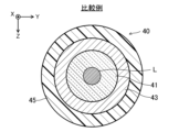
- FIG. FIG. 2 is a cross-sectional view of the transmission fiber viewed from the incident end side.
- FIG. 3A is a diagram showing incident positions of laser light with respect to transmission fibers.
- FIG. 3B is a diagram showing a beam profile of laser light emitted from a transmission fiber.
- FIG. 4A is a diagram showing a state in which a first circular laser beam is emitted to a first member and a second ring-shaped laser beam is emitted to a second member.
- FIG. 4B is a diagram illustrating a state in which the first member and the second member are joined;
- FIG. 4C is a diagram for comparing the shapes of joints.
- FIG. 5A is a diagram showing incident positions of laser light with respect to a transmission fiber as a comparative example.
- FIG. 5B is a diagram showing a beam profile of laser light as a comparative example.
- FIG. 6A is a diagram showing a state in which one laser beam is emitted to the first member and the second member;
- FIG. 6B is a diagram showing a state in which the first member and the second member are joined;
- FIG. 6C is a diagram for comparing the shapes of joints.
- FIG. 7A is a diagram showing the incident position of the laser beam with respect to the transmission fiber in the laser welding device according to Embodiment 2.
- FIG. FIG. 7B is a diagram showing a beam profile of laser light emitted from a transmission fiber.
- FIG. 8A is a diagram showing a state in which a first ring-shaped laser beam is emitted to a first member and a second circular laser beam is emitted to a second member.
- FIG. 8B is a diagram showing a state in which the first member and the second member are joined;
- FIG. 8C is a diagram for comparing the shapes of joints.
- FIG. 9 is a diagram showing the configuration of an optical coupling unit in a laser welding device according to this modification.
- FIG. 10 is a diagram showing a state in which the incident position of laser light is changed.
- the laser welding apparatus 1 includes a laser oscillator 10, an optical coupling unit 20, a focusing unit 30, a transmission fiber 40, a laser processing head 50, a stage 60, and a manipulator 65. .
- the traveling direction of the laser beam L emitted from the laser processing head 50 to the workpiece W is called the Z direction.
- the traveling direction of the laser light L traveling from the optical coupling unit 20 to the condensing unit 30 is called the X direction.
- a direction that crosses the X direction and the Y direction is called the Y direction.
- the laser oscillator 10 has multiple laser modules 11 and a laser beam combiner 12 .
- the laser module 11 emits a laser beam L.
- the laser beam synthesizer 12 synthesizes the laser beams L emitted from the plurality of laser modules 11 and emits them as one laser beam L. As shown in FIG.
- the wavelength of the laser light L is in the range of 900 nm to 1000 nm, but it is not particularly limited to this, and can take other values as appropriate.
- the optical coupling unit 20 has a housing 21 , a folding mirror 22 and an optical path changing mechanism 23 .
- the folding mirror 22 is arranged inside the housing 21 .
- the folding mirror 22 reflects the laser beam L emitted from the laser oscillator 10 toward the optical path changing mechanism 23 .
- the laser oscillator 10 is arranged inside the housing 21 in the example shown in FIG. 1 , it may be arranged outside the housing 21 .
- the optical path changing mechanism 23 has a mirror 24 , a piezo stage 25 and a piezo actuator 26 .
- the mirror 24 reflects the laser light L reflected by the folding mirror 22 toward the condenser lens 32 of the condenser unit 30 .
- the mirror 24 is integrally attached to the piezo actuator 26.
- a piezo actuator 26 is attached to the piezo stage 25 .
- the mirror 24 is tilted around an axis parallel to the Y direction by driving the piezo actuator 26 .
- the mirror 24 changes the optical axis of the laser light L within a predetermined range.
- the folding mirror 22 may be omitted.
- the optical path changing mechanism 23 may be configured to be able to adjust the emission position of the laser light L with respect to the condenser lens 32 in two axial directions (the X direction and the Y direction in FIG. 1). In this case, the configuration may be such that the mirror 24 is moved in two axial directions by the piezoelectric actuator 26 .
- the condensing unit 30 has a housing 31 , a condensing lens 32 , a shutter 33 and a beam damper 34 .
- the condenser lens 32 is arranged inside the housing 31 .
- the condenser lens 32 collects the laser light L reflected by the mirror 24 of the optical path changing mechanism 23 and makes it enter the transmission fiber 40 .
- the condensing unit 30 In order to align the condensing position of the laser light L with the incident end surface of the transmission fiber 40, the condensing unit 30 is provided with a condensing position adjustment section (not shown).
- the condenser lens 32 is moved along the optical path of the laser light L by the condenser position adjusting section.
- the shutter 33 is configured to be movable between the inside of the optical path of the laser beam L and the outside of the optical path.
- the shutter 33 opens and closes the optical path of the laser light L according to a predetermined control signal.
- the shutter 33 is arranged in the optical path of the laser light L, the laser light L reflected by the shutter 33 enters the beam damper 34 and is converted into heat.
- the transmission fiber 40 is connected to the condensing unit 30 and the laser processing head 50 .
- the transmission fiber 40 transmits the laser beam L incident from the light collecting unit 30 to the laser processing head 50 .
- the structure of the transmission fiber 40 will be described later.
- the laser processing head 50 emits the laser beam L incident from the transmission fiber 40 to the work W.
- the laser processing head 50 has a collimation lens 51 , a condenser lens 52 and a protective glass 53 .
- the collimation lens 51 collimates the laser light L emitted from the emission end of the transmission fiber 40 .
- the condenser lens 52 collects the laser light L collimated by the collimation lens 51 .
- the laser beam L condensed by the condensing lens 52 is emitted to the work W, and the work W is laser-welded.
- the laser processing head 50 is provided with a condensing position adjustment section (not shown).
- the condenser lens 52 is moved along the optical path of the laser beam L by the condenser position adjusting section.
- the protective glass 53 is arranged on the emission side of the laser light L from the condenser lens 52 .
- the protective glass 53 prevents fumes and spatters from entering the inside of the laser processing head 50 .
- the stage 60 holds the workpiece W and moves relative to the laser processing head 50 .
- the manipulator 65 holds the laser processing head 50 and moves the laser processing head 50 to a desired position.
- the laser welding device 1 has an optical path control section 71 , a stage control section 72 , a manipulator control section 73 and a laser control section 74 .
- the optical path control section 71 is electrically connected to the piezo actuator 26 and the drive mechanism (not shown) of the shutter 33 .
- the optical path controller 71 controls the operation of the piezo actuator 26 and the opening/closing operation of the shutter 33 .
- the tilt range of the optical path changing mechanism 23 changes according to the magnitude of the control voltage applied from the optical path control section 71 to the piezo actuator 26 . Thereby, the incident position of the laser light L with respect to the transmission fiber 40 can be changed.
- the piezoelectric actuator 26 and the driving mechanism of the shutter 33 may be controlled by separate control units.
- the stage controller 72 is electrically connected to the stage 60 .
- the stage control unit 72 controls the relative movement of the stage 60 with respect to the laser processing head 50 , in other words, the relative position of the stage 60 with respect to the laser beam L incident on the workpiece W.
- the stage controller 72 can move the stage 60 along the XY plane.
- the stage 60 can be rotated around an axis parallel to the Z direction.
- the manipulator control unit 73 is electrically connected to the manipulator 65 .
- the manipulator control section 73 controls the operation of the manipulator 65 . Note that the stage 60 and the manipulator 65 may be controlled by the same control unit.
- the manipulator control unit 73 operates the manipulator 65 to move the laser processing head 50 and emit the laser beam L to the surface of the workpiece W.
- the stage control section 72 and the manipulator control section 73 may be interlocked to operate both the manipulator 65 and the stage 60 .
- only the stage 60 may be moved by the stage control section 72 .
- the laser control unit 74 is connected to the laser oscillator 10 and the power supply 70 .
- a power supply 70 is connected to the laser oscillator 10 .
- the laser control unit 74 controls the timing and period of starting and stopping the output of the laser light L, the output of the laser light L, and the like.
- the optical path control section 71, the stage control section 72, the manipulator control section 73, and the laser control section 74 may be integrated to constitute one control section.
- the transmission fiber 40 has a first core 41 , a second core 42 , a first clad 43 , a second clad 44 and a protective coating 45 .
- the first core 41 is arranged at the axial center of the transmission fiber 40 .
- the first core 41 is formed in a circular shape when viewed from the axial direction.
- the first core 41 is made of quartz glass, for example.
- a first clad 43 is provided on the outer periphery of the first core 41 .
- the first clad 43 is provided coaxially with the first core 41 .
- the first clad 43 is made of a material having a lower refractive index than the first core 41 .
- the first clad 43 is made of, for example, fluorine-doped quartz glass. The refractive index of the first clad 43 is lower than that of the first core 41 .
- a second core 42 is provided on the outer periphery of the first clad 43 .
- the second core 42 is provided coaxially with the first core 41 .
- the second core 42 is formed in a ring shape when viewed from the axial direction.
- the second core 42 is made of the same material as the first core 41, such as quartz glass.
- the refractive index of the second core 42 is higher than that of the first clad 43 .
- a second clad 44 is provided on the outer periphery of the second core 42 .
- the second clad 44 is provided coaxially with the first core 41 and the second core 42 .
- the second clad 44 is made of, for example, fluorine-doped quartz glass.
- the refractive index of the second clad 44 is lower than that of the second core 42 .
- a protective film 45 is provided on the outer peripheral portion of the second clad 44 .
- the protective film 45 is made of synthetic resin, for example.
- the protective film 45 mechanically protects the first core 41, the second core 42, the first clad 43, and the second clad 44 made of quartz glass.
- the protective coating 45 prevents the laser light L from leaking out of the transmission fiber 40 and light from the outside into the transmission fiber 40 .
- the mirror 24 of the optical path changing mechanism 23 is tilted by a predetermined amount around an axis parallel to the Y direction according to the control voltage applied to the piezo actuator 26 .
- the optical axis of the laser beam L reflected by the mirror 24 changes (see the virtual arrow line in FIG. 1).
- the incident position of the laser light L entering the transmission fiber 40 also changes. Using this, the beam profile of the laser light L emitted from the transmission fiber 40 can be changed.
- the laser light L is incident across the first core 41 and the second core 42 .
- the laser light L is incident on a position closer to the first core 41 than the second core 42 is.
- the amount of laser light L incident on the first core 41 is greater than the amount of laser light L incident on the second core 42 .
- the laser beam L is split into a first laser beam L1 incident on the first core 41 and a second laser beam L2 incident on the second core 42 .
- the incident position of the laser beam L with respect to the transmission fiber 40 is adjusted so that the output of the first laser beam L1 is 70% of that of the laser beam L and the output of the second laser beam L2 is 30% of that of the laser beam L. .
- the output of the second laser beam L2 becomes lower than the output of the first laser beam L1.
- the distribution has a central unimodal peak and a ring-shaped peak on the XY plane along the circumference of the central peak.
- the central peak is larger than the ring-shaped peak.
- the beam profile of the laser light L shown in FIG. 3B is simplified and illustrated. For convenience of explanation, only the one-dimensional beam profile in the X direction is shown, but in reality, the beam profile has a similar shape in the Y direction as well.
- the mirror 24 and piezo stage 25 may tilt around an axis parallel to the X direction.
- the beam profile of the laser light L has the same shape.
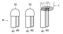
- the work W has a first member W1 and a second member W2.
- the first member W1 is composed of a rectangular prism-shaped terminal.
- the second member W2 is composed of a quadrangular prism-shaped terminal having a cross-sectional area smaller than that of the first member W1.
- the first member W1 and the second member W2 extend vertically and are arranged adjacent to each other.
- the first member W1 and the second member W2 are made of the same material, such as copper (Cu).
- the cross-sectional area of the second member W2 is smaller than the cross-sectional area of the first member W1
- the heat capacity of the second member W2 is smaller than the heat capacity of the first member W1.
- the first step and the second step are executed by operating the optical path control unit 71, the stage control unit 72, the manipulator control unit 73, and the laser control unit 74.
- the laser processing head 50 emits a circular first laser beam L1 from the first core 41 to the first member W1.
- the laser processing head 50 emits the ring-shaped second laser beam L2 from the second core 42 to the second member W2 during the execution of the first step.
- the second member W2 has a smaller heat capacity than the first member W1.
- the output of the second laser beam L2 is lower than that of the first laser beam L1.
- the first member W1 and the second laser beam L2 are irradiated.
- the upper end of the member W2 is melted to form the joint 55.
- the first member W ⁇ b>1 and the second member W ⁇ b>2 are joined via the joining portion 55 .
- a high-output first laser beam L1 is emitted to the first member W1 having a large heat capacity, while a low-output second laser beam L2 is emitted to the second member W2 having a small heat capacity.
- the melting timings of the first member W1 and the second member W2 can be matched to prevent the second member W2 having a small heat capacity from being melted down first.
- the output ratio of the first laser beam L1 and the second laser beam L2 is changed according to the molten state of the first member W1 and the second member W2.
- the output of the first laser beam L1 is 50% of the output of the laser beam L
- the output of the second laser beam L2 is that of the laser beam L.
- the incident position of the laser light L with respect to the transmission fiber 40 may be adjusted so that the output is 50%.
- the beam profile of the laser light L can be changed into a so-called top hat shape, and the shape of the joint 55 can be made clean.
- the laser processing head 50 moves to a position above the second work W.
- the laser processing head 50 emits the first laser beam L1 and the second laser beam L2 to the first member W1 and the second member W2 of the second workpiece W. As shown in FIG.
- the upper ends of the second first member W1 and second member W2 are melted to form a joint 55.
- the first member W ⁇ b>1 and the second member W ⁇ b>2 are joined via the joining portion 55 .
- the laser processing head 50 moves to a position above the third work W. As shown in FIG. The laser processing head 50 emits the first laser beam L1 and the second laser beam L2 to the first member W1 and the second member W2 of the third workpiece W. As shown in FIG.
- the shape of the joint portion 55 of the first work W and the shape of the joint portion 55 of the second work W can be changed. tend to have substantially the same shape.
- the shape of the joint portion 55 between the first member W1 and the second member W2 is stabilized, so that variations in joint strength can be suppressed.
- the transmission fiber 40 uses a single core fiber.
- the transmission fiber 40 has a first core 41 , a first clad 43 and a protective coating 45 .
- a laser beam L is incident on the first core 41 .
- the laser processing head 50 emits laser light L to the first member W1 and the second member W2 of the workpiece W.
- the second member W2 having a smaller heat capacity melts earlier than the first member W1 having a larger heat capacity. becomes.
- the joint portion 55 between the first member W1 and the second member W2 has a large melting amount of the second member W2 and has a shape greatly inclined toward the second member W2 side.
- the melting amount of the first member W1 and the second member W2 is not stable, so the first joint portion 55
- the shape and the shape of the second joint portion 55 are likely to be different shapes. If the shape of the joint 55 becomes unstable in this manner, the joint strength of the joint 55 varies, which is not preferable.
- the melting timings of the first member W1 and the second member W2 are matched to prevent the second member W2 having a small heat capacity from being melted down first. can be suppressed. As a result, since the joint shape of the first member W1 and the second member W2 is stabilized, variations in joint strength can be suppressed.
- the laser light L is incident across the first core 41 and the second core 42 .
- the laser light L is incident on a position closer to the second core 42 than the first core 41 is.
- the amount of laser light L incident on the second core 42 is greater than the amount of laser light L incident on the first core 41 .
- the laser beam L is divided into a first laser beam L1 incident on the second core 42 and a second laser beam L2 incident on the first core 41 .
- the output of the second laser beam L2 is 30% of the output of the laser beam L
- the output of the first laser beam L1 is 70% of the output of the laser beam L. Adjust the incident position.
- the distribution has a central unimodal peak and a ring-shaped peak on the XY plane along the circumference of the central peak.
- the central peak is smaller than the ring-shaped peak.
- the laser processing head 50 emits the ring-shaped first laser beam L1 from the second core 42 to the first member W1.
- the laser processing head 50 emits a circular second laser beam L2 from the first core 41 to the second member W2 during execution of the first step.
- the second member W2 has a smaller heat capacity than the first member W1.
- the output of the second laser beam L2 is lower than that of the first laser beam L1.
- the first member W1 and the second laser beam L2 are irradiated.
- the upper end of the member W2 is melted to form the joint 55.
- the first member W ⁇ b>1 and the second member W ⁇ b>2 are joined via the joining portion 55 .
- the laser processing head 50 moves to a position above the second work W.
- the laser processing head 50 emits the first laser beam L1 and the second laser beam L2 to the first member W1 and the second member W2 of the second workpiece W. As shown in FIG.
- the upper ends of the second first member W1 and second member W2 are melted to form a joint 55.
- the first member W ⁇ b>1 and the second member W ⁇ b>2 are joined via the joining portion 55 .
- the shape of the joint portion 55 of the first work W and the shape of the second work W can be changed.
- the shape is likely to be substantially the same as the shape of the joint portion 55 .
- the shape of the joint portion 55 between the first member W1 and the second member W2 is stabilized, so that variations in joint strength can be suppressed.
- the optical coupling unit 20 includes a first laser oscillator 81, a second laser oscillator 82, a first mirror 83, a second mirror 84, a first adjusting mechanism 85, and a second adjusting mechanism. 86.
- the first laser oscillator 81 emits a first laser beam L1 based on a command from the laser control section 74.
- the second laser oscillator 82 emits the second laser light L2 based on a command from the laser control section 74. As shown in FIG. The output of the second laser beam L2 is lower than that of the first laser beam L1.
- the first mirror 83 reflects the first laser beam L1 emitted from the first laser oscillator 81 and guides it to the first adjusting mechanism 85 .
- the second mirror 84 reflects the second laser beam L2 emitted from the second laser oscillator 82 and guides it to the second adjustment mechanism 86 .
- the first adjustment mechanism 85 is composed of, for example, a biaxial MEMS (Micro Electro Mechanical Systems) mirror whose angle can be changed in biaxial directions.
- the first adjustment mechanism 85 further reflects the first laser beam L ⁇ b>1 reflected by the first mirror 83 and guides it to the transmission fiber 40 .
- the first adjustment mechanism 85 changes the incident position of the first laser beam L1 with respect to the transmission fiber 40 by changing the angle of the mirror in two axial directions. This allows the first laser beam L1 to selectively enter the first core 41 or the second core 42 of the transmission fiber 40 .
- the first laser beam L1 is incident on the first core 41 .
- the first laser beam L1 is incident on the second core 42 .
- the second adjustment mechanism 86 is composed of, for example, a biaxial MEMS mirror (Micro Electro Mechanical Systems) whose angle can be changed in biaxial directions.
- the second adjustment mechanism 86 further reflects the second laser beam L2 reflected by the second mirror 84 and guides it to the transmission fiber 40 .
- the second adjustment mechanism 86 changes the incident position of the second laser beam L2 with respect to the transmission fiber 40 by changing the angle of the mirror in two axial directions. This allows the second laser beam L2 to selectively enter the first core 41 or the second core 42 of the transmission fiber 40 .
- the second laser beam L2 is incident on the second core 42 .
- the second laser beam L2 is incident on the first core 41 .
- first adjustment mechanism 85 and the second adjustment mechanism 86 may be configured using a biaxial galvanometer (galvanomirror) instead of the biaxial MEMS mirror. Also, the first adjusting mechanism 85 and the second adjusting mechanism 86 may be configured by the optical path changing mechanism 23 of the above-described embodiment.
- the first laser beam L1 may be a short-wavelength laser beam having a shorter wavelength than the second laser beam L2.
- the short-wavelength first laser light L1 may be blue laser light or green laser light laser light with a wavelength of 600 nm or less (for example, 266 nm to 600 nm).
- the long-wavelength second laser light L2 may be infrared laser light with a wavelength of 800 nm or more (for example, about 800 nm to 16000 nm).
- the first member W1 or the second member W2 is made of, for example, copper (Cu), gold (Au), or silver, which is a highly reflective material having a relatively high laser light reflectance compared to iron (Fe).
- Cu copper
- Au gold
- silver silver
- the highly reflective material is easily melted by emitting a short-wavelength laser beam, which is easily absorbed by the highly reflective material, to the highly reflective material.
- a step of preheating the first member W1 and the second member W2 by emitting the laser light L to the first member W1 and the second member W2 is performed before the first step.
- the first member W1 and the second member W2 can be easily melted in the first step and the second step.
- a step of adjusting the spot diameter of the laser beam L at the welded portion of the first member W1 and the second member W2 may be performed before the first step.
- the laser beam L can be applied to the entire range of the welding points. can be emitted.
- the present invention has a highly practical effect of suppressing variations in bonding strength between the first member and the second member having different heat capacities, and is therefore extremely useful and industrially applicable. Very likely.
Abstract
This laser machining head 50 emits a first laser beam L1 to a first member W1 from a first core 41, and emits a second laser beam L2 to a second member W2 from a second core 42. The thermal capacity of the second member W2 is higher than that of the first member W1. The output of the second laser beam L2 is lower than that of the first laser beam L1.
Description
本発明は、レーザ溶接方法に関するものである。
The present invention relates to a laser welding method.
特許文献1には、2つのバスバーにそれぞれ突起部が設けられ、2つの突起部にレーザ照射を行うことにより、突起部を溶融させてバスバー同士を接合するようにしたレーザ溶接接合構造が開示されている。
Patent Literature 1 discloses a laser welding joint structure in which two busbars are provided with projections, and the two projections are irradiated with a laser to melt the projections and join the busbars together. ing.
ところで、2つの突起部の断面積が異なる場合、断面積の小さな突起部は、断面積の大きな突起部よりも熱容量が小さくなる。そのため、2つの突起部に対してレーザ光を出射すると、熱容量の小さな突起部が先に溶け落ち、接合部分の形状や接合強度にばらつきが生じてしまう。
By the way, when the cross-sectional areas of the two protrusions are different, the heat capacity of the protrusion with a small cross-sectional area is smaller than that of the protrusion with a large cross-sectional area. Therefore, when a laser beam is emitted to two protrusions, the protrusion having a small heat capacity melts down first, resulting in variation in the shape and bonding strength of the joint.
本発明は、かかる点に鑑みてなされたものであり、その目的は、熱容量の異なる第1部材及び第2部材の接合強度がばらつくのを抑えることにある。
The present invention has been made in view of this point, and its object is to suppress variations in the bonding strength between the first member and the second member having different heat capacities.
第1の態様は、伝送ファイバで伝送されたレーザ光を出射して、第1部材と、該第1部材よりも熱容量が小さい第2部材とを溶接するレーザ溶接方法であって、前記伝送ファイバは、第1コアと、該第1コアの外周部に設けられた第2コアとを有し、前記第1部材に対して、前記第1コア又は前記第2コアの一方から第1レーザ光を出射する第1工程と、前記第1工程の実行中に、前記第2部材に対して、前記第1コア又は前記第2コアの他方から前記第1レーザ光よりも出力の低い第2レーザ光を出射する第2工程とを備えたことを特徴とする。
A first aspect is a laser welding method of emitting a laser beam transmitted through a transmission fiber to weld a first member and a second member having a smaller heat capacity than the first member, wherein the transmission fiber has a first core and a second core provided on the outer periphery of the first core, and a first laser beam is emitted from either the first core or the second core to the first member and a second laser having a lower output than the first laser light from the other of the first core and the second core to the second member during the execution of the first step and a second step of emitting light.
第1の態様では、伝送ファイバは、第1コアと、第2コアとを有する。第2コアは、第1コアの外周部に設けられる。第1工程では、第1コア又は第2コアの一方から第1部材に対して第1レーザ光を出射する。第2工程では、第1工程の実行中に、第1コア又は第2コアの他方から第2部材に対して第2レーザ光を出射する。第2部材は、第1部材よりも熱容量が小さい。第2レーザ光は、第1レーザ光よりも出力が低い。
In a first aspect, the transmission fiber has a first core and a second core. The second core is provided on the outer periphery of the first core. In the first step, a first laser beam is emitted from one of the first core and the second core to the first member. In the second step, the second laser beam is emitted from the other of the first core and the second core to the second member during execution of the first step. The second member has a smaller heat capacity than the first member. The second laser light has a lower output than the first laser light.
これにより、第1部材及び第2部材の溶融タイミングを合わせて、熱容量の小さな第2部材が先に溶け落ちてしまうのを抑えることができる。その結果、第1部材及び第2部材の接合形状が安定するので、接合強度がばらつくのを抑えることができる。
As a result, the melting timing of the first member and the second member can be matched to prevent the second member, which has a small heat capacity, from being melted down first. As a result, since the joint shape of the first member and the second member is stabilized, variations in joint strength can be suppressed.
第2の態様は、第1の態様において、前記第1工程及び前記第2工程では、前記第1コア及び前記第2コアに入射される前記レーザ光の比率を変更することで、前記第1レーザ光及び前記第2レーザ光の出力を変更することを特徴とする。
In a second aspect, in the first aspect, in the first step and the second step, by changing the ratio of the laser light incident on the first core and the second core, the first It is characterized by changing the outputs of the laser light and the second laser light.
第2の態様では、1つのレーザ発振器から出射されるレーザ光を、第1コアと第2コアとに適切な比率で分配することで、第1レーザ光及び第2レーザ光の出力を変更することができる。
In the second aspect, by distributing the laser light emitted from one laser oscillator to the first core and the second core in an appropriate ratio, the outputs of the first laser light and the second laser light are changed. be able to.
第3の態様は、第1又は2の態様において、前記第1工程では、前記第1コアから前記第1レーザ光を出射させ、前記第2工程では、前記第2コアから前記第2レーザ光を出射させることを特徴とする。
In a third aspect, in the first or second aspect, in the first step, the first laser beam is emitted from the first core, and in the second step, the second laser beam is emitted from the second core. is emitted.
第3の態様では、円形状の第1コアから高出力の第1レーザ光を出射し、リング状の第2コアから低出力の第2レーザ光を出射することができる。
In the third aspect, a high-power first laser beam can be emitted from the circular first core, and a low-power second laser beam can be emitted from the ring-shaped second core.
第4の態様は、第1又は2の態様において、前記第1工程では、前記第2コアから前記第1レーザ光を出射させ、前記第2工程では、前記第1コアから前記第2レーザ光を出射させることを特徴とする。
In a fourth aspect, in the first or second aspect, in the first step, the first laser beam is emitted from the second core, and in the second step, the second laser beam is emitted from the first core. is emitted.
第4の態様では、リング状の第2コアから高出力の第1レーザ光を出射し、円形状の第1コアから低出力の第2レーザ光を出射することができる。
In the fourth aspect, a high-power first laser beam can be emitted from the ring-shaped second core, and a low-power second laser beam can be emitted from the circular first core.
第5の態様は、第1乃至4の態様のうち何れか1つにおいて、前記第1工程の前に、前記第1部材及び前記第2部材に対して前記レーザ光をそれぞれ出射して、該第1部材及び該第2部材を予熱する工程を備えたことを特徴とする。
In a fifth aspect, in any one of the first to fourth aspects, before the first step, the laser beam is emitted to each of the first member and the second member, It is characterized by comprising a step of preheating the first member and the second member.
第5の態様では、第1部材及び第2部材をそれぞれ予熱することで、第1工程及び第2工程において、第1部材及び第2部材を溶融させやすくなる。
In the fifth aspect, preheating the first member and the second member makes it easier to melt the first member and the second member in the first step and the second step.
第6の態様は、第1乃至5の態様のうち何れか1つにおいて、前記第1工程の前に、前記第1部材及び前記第2部材の溶接箇所における前記レーザ光のスポット径を調整する工程を備えたことを特徴とする。
A sixth aspect is any one of the first to fifth aspects, wherein, before the first step, the spot diameter of the laser beam at the welded portion of the first member and the second member is adjusted. It is characterized by comprising steps.
第6の態様では、レーザ光をデフォーカスして、第1部材及び第2部材の溶接箇所をレーザ光のスポット径の範囲内に収めることで、溶接箇所の全範囲にレーザ光を出射することができる。
In the sixth aspect, by defocusing the laser beam and keeping the welding points of the first member and the second member within the range of the spot diameter of the laser beam, the laser beam is emitted to the entire range of the welding points. can be done.
また、レーザ光のスポット径を適切に調整することで、第1部材及び第2部材の溶接箇所よりも外方にレーザ光が漏れるのを抑えることができる。
Also, by appropriately adjusting the spot diameter of the laser beam, it is possible to suppress the leakage of the laser beam to the outside of the welded portion of the first member and the second member.
第7の態様は、第1乃至6の態様のうち何れか1つにおいて、前記第1レーザ光及び前記第2レーザ光は、互いに波長が異なることを特徴とする。
A seventh aspect is characterized in that, in any one of the first to sixth aspects, the first laser light and the second laser light have different wavelengths.
第7の態様では、第1部材又は第2部材が高反射材料で構成されている場合に、高反射材料に吸収されやすい波長のレーザ光を出射することで、高反射材料を溶融させやすくなる。
In the seventh aspect, when the first member or the second member is made of a highly reflective material, the highly reflective material is easily melted by emitting a laser beam having a wavelength that is easily absorbed by the highly reflective material. .
第8の態様は、第1乃至7の態様のうち何れか1つにおいて、前記第1工程及び前記第2工程の実行中に、前記第1レーザ光及び前記第2レーザ光のうち少なくとも一方の出力を調整する工程を備えたことを特徴とする。
According to an eighth aspect, in any one of the first to seventh aspects, at least one of the first laser beam and the second laser beam is emitted during the execution of the first step and the second step. It is characterized by comprising a step of adjusting the output.
第8の態様では、第1レーザ光の出力を高くすることで、第1部材を溶融させやすくなる。また、第2レーザ光の出力を低くすることで、第2部材が溶けすぎるのを抑えることができる。
In the eighth aspect, by increasing the output of the first laser beam, it becomes easier to melt the first member. In addition, by reducing the output of the second laser beam, it is possible to suppress excessive melting of the second member.
本開示の態様によれば、熱容量の異なる第1部材及び第2部材の接合強度がばらつくのを抑えることができる。
According to the aspect of the present disclosure, variations in bonding strength between the first member and the second member having different heat capacities can be suppressed.
以下、本発明の実施形態を図面に基づいて説明する。なお、以下の好ましい実施形態の説明は、本質的に例示に過ぎず、本発明、その適用物或いはその用途を制限することを意図するものではない。
Hereinafter, embodiments of the present invention will be described based on the drawings. It should be noted that the following description of preferred embodiments is essentially merely an example, and is not intended to limit the present invention, its applications, or its uses.
《実施形態1》
図1に示すように、レーザ溶接装置1は、レーザ発振器10と、光結合ユニット20と、集光ユニット30と、伝送ファイバ40と、レーザ加工ヘッド50と、ステージ60と、マニピュレータ65とを備える。 <<Embodiment 1>>
As shown in FIG. 1, the laser welding apparatus 1 includes alaser oscillator 10, an optical coupling unit 20, a focusing unit 30, a transmission fiber 40, a laser processing head 50, a stage 60, and a manipulator 65. .
図1に示すように、レーザ溶接装置1は、レーザ発振器10と、光結合ユニット20と、集光ユニット30と、伝送ファイバ40と、レーザ加工ヘッド50と、ステージ60と、マニピュレータ65とを備える。 <<Embodiment 1>>
As shown in FIG. 1, the laser welding apparatus 1 includes a
なお、以下の説明において、レーザ加工ヘッド50からワークWに出射されるレーザ光Lの進行方向をZ方向と呼ぶ。また、光結合ユニット20から集光ユニット30に向かうレーザ光Lの進行方向をX方向と呼ぶ。また、X方向及びY方向とそれぞれ交差する方向をY方向と呼ぶ。
In the following description, the traveling direction of the laser beam L emitted from the laser processing head 50 to the workpiece W is called the Z direction. Also, the traveling direction of the laser light L traveling from the optical coupling unit 20 to the condensing unit 30 is called the X direction. A direction that crosses the X direction and the Y direction is called the Y direction.
レーザ発振器10は、複数のレーザモジュール11と、レーザ光合成器12とを有する。レーザモジュール11は、レーザ光Lを出射する。レーザ光合成器12は、複数のレーザモジュール11からそれぞれ出射されたレーザ光Lを合成して、1本のレーザ光Lとして出射する。
The laser oscillator 10 has multiple laser modules 11 and a laser beam combiner 12 . The laser module 11 emits a laser beam L. As shown in FIG. The laser beam synthesizer 12 synthesizes the laser beams L emitted from the plurality of laser modules 11 and emits them as one laser beam L. As shown in FIG.
本実施形態では、レーザ光Lの波長は、900nm~1000nmの範囲としているが、特にこれに限定されず、適宜、他の値を取りうる。
In this embodiment, the wavelength of the laser light L is in the range of 900 nm to 1000 nm, but it is not particularly limited to this, and can take other values as appropriate.
光結合ユニット20は、筐体21と、折り返しミラー22と、光路変更機構23とを有する。折り返しミラー22は、筐体21の内部に配置される。折り返しミラー22は、レーザ発振器10から出射されたレーザ光Lを、光路変更機構23に向けて反射する。
The optical coupling unit 20 has a housing 21 , a folding mirror 22 and an optical path changing mechanism 23 . The folding mirror 22 is arranged inside the housing 21 . The folding mirror 22 reflects the laser beam L emitted from the laser oscillator 10 toward the optical path changing mechanism 23 .
なお、図1に示す例では、レーザ発振器10が筐体21の内部に配置されているが、筐体21の外部に配置されてもよい。
Although the laser oscillator 10 is arranged inside the housing 21 in the example shown in FIG. 1 , it may be arranged outside the housing 21 .
光路変更機構23は、ミラー24と、ピエゾステージ25と、ピエゾアクチュエータ26とを有する。ミラー24は、折り返しミラー22で反射されたレーザ光Lを、集光ユニット30の集光レンズ32に向けて反射する。
The optical path changing mechanism 23 has a mirror 24 , a piezo stage 25 and a piezo actuator 26 . The mirror 24 reflects the laser light L reflected by the folding mirror 22 toward the condenser lens 32 of the condenser unit 30 .
ミラー24は、ピエゾアクチュエータ26に一体に取り付けられる。ピエゾアクチュエータ26は、ピエゾステージ25に取り付けられる。ミラー24は、ピエゾアクチュエータ26の駆動によって、Y方向と平行な軸回りに傾動する。ミラー24は、レーザ光Lの光軸を所定の範囲で変化させる。
The mirror 24 is integrally attached to the piezo actuator 26. A piezo actuator 26 is attached to the piezo stage 25 . The mirror 24 is tilted around an axis parallel to the Y direction by driving the piezo actuator 26 . The mirror 24 changes the optical axis of the laser light L within a predetermined range.
なお、光路変更機構23に対してレーザ光Lが直接入射される場合は、折り返しミラー22を省略してもよい。また、光路変更機構23は、レーザ光Lの集光レンズ32に対する出射位置を2軸方向(図1におけるX方向及びY方向)に調整可能な構成であっても良い。この場合、ミラー24をピエゾアクチュエータ26により2軸方向に可動する構成であっても良い。
In addition, when the laser light L is directly incident on the optical path changing mechanism 23, the folding mirror 22 may be omitted. Further, the optical path changing mechanism 23 may be configured to be able to adjust the emission position of the laser light L with respect to the condenser lens 32 in two axial directions (the X direction and the Y direction in FIG. 1). In this case, the configuration may be such that the mirror 24 is moved in two axial directions by the piezoelectric actuator 26 .
集光ユニット30は、筐体31と、集光レンズ32と、シャッタ33と、ビームダンパ34とを有する。
The condensing unit 30 has a housing 31 , a condensing lens 32 , a shutter 33 and a beam damper 34 .
集光レンズ32は、筐体31の内部に配置される。集光レンズ32は、光路変更機構23のミラー24で反射されたレーザ光Lを集光して、伝送ファイバ40に入射させる。
The condenser lens 32 is arranged inside the housing 31 . The condenser lens 32 collects the laser light L reflected by the mirror 24 of the optical path changing mechanism 23 and makes it enter the transmission fiber 40 .
なお、レーザ光Lの集光位置を伝送ファイバ40の入射端面に合わせるために、集光ユニット30には、図示しない集光位置調整部が設けられる。集光レンズ32は、集光位置調整部によって、レーザ光Lの光路に沿って移動する。
In order to align the condensing position of the laser light L with the incident end surface of the transmission fiber 40, the condensing unit 30 is provided with a condensing position adjustment section (not shown). The condenser lens 32 is moved along the optical path of the laser light L by the condenser position adjusting section.
シャッタ33は、レーザ光Lの光路内と光路外との間を移動可能に構成される。シャッタ33は、所定の制御信号に応じてレーザ光Lの光路を開閉する。シャッタ33がレーザ光Lの光路内に配置される場合、シャッタ33で反射されたレーザ光Lは、ビームダンパ34に入射され、熱に変換される。
The shutter 33 is configured to be movable between the inside of the optical path of the laser beam L and the outside of the optical path. The shutter 33 opens and closes the optical path of the laser light L according to a predetermined control signal. When the shutter 33 is arranged in the optical path of the laser light L, the laser light L reflected by the shutter 33 enters the beam damper 34 and is converted into heat.
伝送ファイバ40は、集光ユニット30と、レーザ加工ヘッド50とに接続される。伝送ファイバ40は、集光ユニット30から入射されたレーザ光Lをレーザ加工ヘッド50まで伝送する。なお、伝送ファイバ40の構造については後述する。
The transmission fiber 40 is connected to the condensing unit 30 and the laser processing head 50 . The transmission fiber 40 transmits the laser beam L incident from the light collecting unit 30 to the laser processing head 50 . The structure of the transmission fiber 40 will be described later.
レーザ加工ヘッド50は、伝送ファイバ40から入射されたレーザ光LをワークWに出射する。レーザ加工ヘッド50は、コリメーションレンズ51と、集光レンズ52と、保護ガラス53とを有する。
The laser processing head 50 emits the laser beam L incident from the transmission fiber 40 to the work W. The laser processing head 50 has a collimation lens 51 , a condenser lens 52 and a protective glass 53 .
コリメーションレンズ51は、伝送ファイバ40の出射端から出射されたレーザ光Lを平行化する。
The collimation lens 51 collimates the laser light L emitted from the emission end of the transmission fiber 40 .
集光レンズ52は、コリメーションレンズ51で平行化されたレーザ光Lを集光する。集光レンズ52で集光されたレーザ光Lは、ワークWに出射され、ワークWをレーザ溶接する。
The condenser lens 52 collects the laser light L collimated by the collimation lens 51 . The laser beam L condensed by the condensing lens 52 is emitted to the work W, and the work W is laser-welded.
なお、ワークWにおけるレーザ光Lのスポット径を調整するために、レーザ加工ヘッド50には、図示しない集光位置調整部が設けられる。集光レンズ52は、集光位置調整部によって、レーザ光Lの光路に沿って移動する。
In order to adjust the spot diameter of the laser beam L on the workpiece W, the laser processing head 50 is provided with a condensing position adjustment section (not shown). The condenser lens 52 is moved along the optical path of the laser beam L by the condenser position adjusting section.
保護ガラス53は、集光レンズ52よりもレーザ光Lの出射側に配置される。保護ガラス53は、レーザ加工ヘッド50内部にヒュームやスパッタが侵入するのを抑える。
The protective glass 53 is arranged on the emission side of the laser light L from the condenser lens 52 . The protective glass 53 prevents fumes and spatters from entering the inside of the laser processing head 50 .
ステージ60は、ワークWを保持するとともに、レーザ加工ヘッド50に対して相対的に移動する。マニピュレータ65は、レーザ加工ヘッド50を保持するとともに、レーザ加工ヘッド50を所望の位置に移動させる。
The stage 60 holds the workpiece W and moves relative to the laser processing head 50 . The manipulator 65 holds the laser processing head 50 and moves the laser processing head 50 to a desired position.
レーザ溶接装置1は、光路制御部71と、ステージ制御部72と、マニピュレータ制御部73と、レーザ制御部74とを有する。
The laser welding device 1 has an optical path control section 71 , a stage control section 72 , a manipulator control section 73 and a laser control section 74 .
光路制御部71は、ピエゾアクチュエータ26と、シャッタ33の駆動機構(図示せず)とに、電気的に接続される。光路制御部71は、ピエゾアクチュエータ26の動作及びシャッタ33の開閉動作を制御する。
The optical path control section 71 is electrically connected to the piezo actuator 26 and the drive mechanism (not shown) of the shutter 33 . The optical path controller 71 controls the operation of the piezo actuator 26 and the opening/closing operation of the shutter 33 .
光路変更機構23の傾動範囲は、光路制御部71からピエゾアクチュエータ26に印加する制御電圧の大きさに応じて変化する。これにより、伝送ファイバ40に対するレーザ光Lの入射位置を変化させることができる。なお、ピエゾアクチュエータ26とシャッタ33の駆動機構とは、それぞれ別の制御部で制御されてもよい。
The tilt range of the optical path changing mechanism 23 changes according to the magnitude of the control voltage applied from the optical path control section 71 to the piezo actuator 26 . Thereby, the incident position of the laser light L with respect to the transmission fiber 40 can be changed. Note that the piezoelectric actuator 26 and the driving mechanism of the shutter 33 may be controlled by separate control units.
ステージ制御部72は、ステージ60に電気的に接続される。ステージ制御部72は、レーザ加工ヘッド50に対するステージ60の相対動作、言い換えるとワークWに入射されるレーザ光Lに対するステージ60の相対位置を制御する。
The stage controller 72 is electrically connected to the stage 60 . The stage control unit 72 controls the relative movement of the stage 60 with respect to the laser processing head 50 , in other words, the relative position of the stage 60 with respect to the laser beam L incident on the workpiece W.
例えば、ステージ制御部72により、ステージ60をXY平面に沿って移動させることができる。あるいは、ステージ60は、Z方向と平行な軸回りに回転させることができる。
For example, the stage controller 72 can move the stage 60 along the XY plane. Alternatively, the stage 60 can be rotated around an axis parallel to the Z direction.
マニピュレータ制御部73は、マニピュレータ65に電気的に接続される。マニピュレータ制御部73は、マニピュレータ65の動作を制御する。なお、ステージ60とマニピュレータ65とが同じ制御部で制御されていてもよい。
The manipulator control unit 73 is electrically connected to the manipulator 65 . The manipulator control section 73 controls the operation of the manipulator 65 . Note that the stage 60 and the manipulator 65 may be controlled by the same control unit.
マニピュレータ制御部73によりマニピュレータ65を動作させてレーザ加工ヘッド50を移動させ、レーザ光LをワークWの表面に出射させる。なお、ステージ制御部72とマニピュレータ制御部73とを連動させ、マニピュレータ65とステージ60の両方を動作させるようにしてもよい。また、ステージ制御部72によりステージ60のみを移動させてもよい。
The manipulator control unit 73 operates the manipulator 65 to move the laser processing head 50 and emit the laser beam L to the surface of the workpiece W. Note that the stage control section 72 and the manipulator control section 73 may be interlocked to operate both the manipulator 65 and the stage 60 . Alternatively, only the stage 60 may be moved by the stage control section 72 .
レーザ制御部74は、レーザ発振器10と、電源70とに接続される。電源70は、レーザ発振器10に接続される。レーザ制御部74は、レーザ光Lの出力開始及び出力停止のタイミングや期間、レーザ光Lの出力などを制御する。
The laser control unit 74 is connected to the laser oscillator 10 and the power supply 70 . A power supply 70 is connected to the laser oscillator 10 . The laser control unit 74 controls the timing and period of starting and stopping the output of the laser light L, the output of the laser light L, and the like.
なお、光路制御部71、ステージ制御部72、マニピュレータ制御部73及びレーザ制御部74が一体化されて、一つの制御部を構成してもよい。
The optical path control section 71, the stage control section 72, the manipulator control section 73, and the laser control section 74 may be integrated to constitute one control section.
〈伝送ファイバの構成〉
図2に示すように、伝送ファイバ40は、第1コア41と、第2コア42と、第1クラッド43と、第2クラッド44と、保護皮膜45とを有する。 <Structure of transmission fiber>
As shown in FIG. 2 , thetransmission fiber 40 has a first core 41 , a second core 42 , a first clad 43 , a second clad 44 and a protective coating 45 .
図2に示すように、伝送ファイバ40は、第1コア41と、第2コア42と、第1クラッド43と、第2クラッド44と、保護皮膜45とを有する。 <Structure of transmission fiber>
As shown in FIG. 2 , the
第1コア41は、伝送ファイバ40の軸心に配置される。第1コア41は、軸方向から見て円形状に形成される。第1コア41は、例えば、石英ガラスで形成される。
The first core 41 is arranged at the axial center of the transmission fiber 40 . The first core 41 is formed in a circular shape when viewed from the axial direction. The first core 41 is made of quartz glass, for example.
第1コア41の外周部には、第1クラッド43が設けられる。第1クラッド43は、第1コア41と同軸に設けられる。第1クラッド43は、第1コア41よりも屈折率の低い材料で形成される。第1クラッド43は、例えば、フッ素がドープされた石英ガラスで構成される。第1クラッド43の屈折率は、第1コア41の屈折率よりも低い。
A first clad 43 is provided on the outer periphery of the first core 41 . The first clad 43 is provided coaxially with the first core 41 . The first clad 43 is made of a material having a lower refractive index than the first core 41 . The first clad 43 is made of, for example, fluorine-doped quartz glass. The refractive index of the first clad 43 is lower than that of the first core 41 .
第1クラッド43の外周部には、第2コア42が設けられる。第2コア42は、第1コア41と同軸に設けられる。第2コア42は、軸方向から見てリング状に形成される。第2コア42は、第1コア41と同じ材質、例えば、石英ガラスで構成される。第2コア42の屈折率は、第1クラッド43の屈折率よりも高い。
A second core 42 is provided on the outer periphery of the first clad 43 . The second core 42 is provided coaxially with the first core 41 . The second core 42 is formed in a ring shape when viewed from the axial direction. The second core 42 is made of the same material as the first core 41, such as quartz glass. The refractive index of the second core 42 is higher than that of the first clad 43 .
第2コア42の外周部には、第2クラッド44が設けられる。第2クラッド44は、第1コア41及び第2コア42と同軸に設けられる。第2クラッド44は、例えば、フッ素がドープされた石英ガラスで構成される。第2クラッド44の屈折率は、第2コア42の屈折率よりも低い。
A second clad 44 is provided on the outer periphery of the second core 42 . The second clad 44 is provided coaxially with the first core 41 and the second core 42 . The second clad 44 is made of, for example, fluorine-doped quartz glass. The refractive index of the second clad 44 is lower than that of the second core 42 .
第2クラッド44の外周部には、保護皮膜45が設けられる。保護皮膜45は、例えば、合成樹脂で構成される。保護皮膜45は、石英ガラスで構成された第1コア41、第2コア42、第1クラッド43、及び第2クラッド44を機械的に保護する。保護皮膜45は、伝送ファイバ40からレーザ光Lが漏れ出したり、外部から伝送ファイバ40に光が漏れ込むのを抑える。
A protective film 45 is provided on the outer peripheral portion of the second clad 44 . The protective film 45 is made of synthetic resin, for example. The protective film 45 mechanically protects the first core 41, the second core 42, the first clad 43, and the second clad 44 made of quartz glass. The protective coating 45 prevents the laser light L from leaking out of the transmission fiber 40 and light from the outside into the transmission fiber 40 .
〈レーザ光のビームプロファイルを変化させる手順〉
図1に示すように、光路変更機構23のミラー24は、ピエゾアクチュエータ26に印加される制御電圧に応じて、Y方向と平行な軸回りに所定量傾動する。これにより、ミラー24で反射されたレーザ光Lの光軸が変化する(図1の仮想矢印線参照)。 <Procedure for changing the beam profile of the laser light>
As shown in FIG. 1, themirror 24 of the optical path changing mechanism 23 is tilted by a predetermined amount around an axis parallel to the Y direction according to the control voltage applied to the piezo actuator 26 . As a result, the optical axis of the laser beam L reflected by the mirror 24 changes (see the virtual arrow line in FIG. 1).
図1に示すように、光路変更機構23のミラー24は、ピエゾアクチュエータ26に印加される制御電圧に応じて、Y方向と平行な軸回りに所定量傾動する。これにより、ミラー24で反射されたレーザ光Lの光軸が変化する(図1の仮想矢印線参照)。 <Procedure for changing the beam profile of the laser light>
As shown in FIG. 1, the
ミラー24で反射されたレーザ光Lの光軸が変化すると、伝送ファイバ40に入射されるレーザ光Lの入射位置も変化する。このことを利用して、伝送ファイバ40から出射されるレーザ光Lのビームプロファイルを変化させることができる。
When the optical axis of the laser light L reflected by the mirror 24 changes, the incident position of the laser light L entering the transmission fiber 40 also changes. Using this, the beam profile of the laser light L emitted from the transmission fiber 40 can be changed.
図3Aに示す例では、レーザ光Lは、第1コア41と第2コア42とに跨って入射される。レーザ光Lは、第2コア42よりも第1コア41寄りの位置に入射される。第1コア41に入射されるレーザ光Lの光量は、第2コア42に入射されるレーザ光Lの光量よりも多くなる。レーザ光Lは、第1コア41に入射される第1レーザ光L1と、第2コア42に入射される第2レーザ光L2とに分配される。
In the example shown in FIG. 3A, the laser light L is incident across the first core 41 and the second core 42 . The laser light L is incident on a position closer to the first core 41 than the second core 42 is. The amount of laser light L incident on the first core 41 is greater than the amount of laser light L incident on the second core 42 . The laser beam L is split into a first laser beam L1 incident on the first core 41 and a second laser beam L2 incident on the second core 42 .
このように、1つのレーザ発振器10から出射されるレーザ光Lを、第1コア41と第2コア42とに適切な比率で分配することで、第1レーザ光L1及び第2レーザ光L2の出力を変更することができる。
In this way, by distributing the laser light L emitted from one laser oscillator 10 to the first core 41 and the second core 42 at an appropriate ratio, the first laser light L1 and the second laser light L2 You can change the output.
例えば、第1レーザ光L1がレーザ光Lの70%の出力となり、第2レーザ光L2がレーザ光Lの30%の出力となるように、伝送ファイバ40に対するレーザ光Lの入射位置を調整する。これにより、第2レーザ光L2の出力は、第1レーザ光L1の出力よりも低くなる。
For example, the incident position of the laser beam L with respect to the transmission fiber 40 is adjusted so that the output of the first laser beam L1 is 70% of that of the laser beam L and the output of the second laser beam L2 is 30% of that of the laser beam L. . As a result, the output of the second laser beam L2 becomes lower than the output of the first laser beam L1.
図3Bに示すように、レーザ光Lのビームプロファイルは、第1コア41の軸心に対応するX=0となる中央位置と、X=0となる位置を挟んで第2コア42に対応する位置とに、それぞれピークが現れる形状となる。
As shown in FIG. 3B, the beam profile of the laser light L corresponds to the central position where X=0 corresponding to the axial center of the first core 41 and the second core 42 across the position where X=0. It becomes a shape in which a peak appears at each position.
実際には、中央の単峰状のピークと、中央のピークの周囲に沿ってXY平面上にリング状のピークを有する分布となる。ここで、中央のピークは、リング状のピークよりも大きい。
In reality, the distribution has a central unimodal peak and a ring-shaped peak on the XY plane along the circumference of the central peak. Here, the central peak is larger than the ring-shaped peak.
図3Bに示すレーザ光Lのビームプロファイルは簡略化して図示している。また、説明の便宜上、X方向に関する一次元のビームプロファイルのみ図示しているが、実際には、Y方向にも同様の形状のビームプロファイルとなる。
The beam profile of the laser light L shown in FIG. 3B is simplified and illustrated. For convenience of explanation, only the one-dimensional beam profile in the X direction is shown, but in reality, the beam profile has a similar shape in the Y direction as well.
なお、ミラー24及びピエゾステージ25は、X方向と平行な軸回りに傾動してもよい。伝送ファイバ40の軸心からXY平面上で等距離の位置にレーザ光Lが入射した場合、レーザ光Lのビームプロファイルは同じ形状となる。
Note that the mirror 24 and piezo stage 25 may tilt around an axis parallel to the X direction. When the laser light L is incident on positions equidistant from the axial center of the transmission fiber 40 on the XY plane, the beam profile of the laser light L has the same shape.
図4Aに示すように、ワークWは、第1部材W1と、第2部材W2とを有する。第1部材W1は、四角柱状の端子で構成される。第2部材W2は、第1部材W1よりも断面積が小さい四角柱状の端子で構成される。第1部材W1及び第2部材W2は、上下方向に延びるとともに、互いに隣接して配置される。
As shown in FIG. 4A, the work W has a first member W1 and a second member W2. The first member W1 is composed of a rectangular prism-shaped terminal. The second member W2 is composed of a quadrangular prism-shaped terminal having a cross-sectional area smaller than that of the first member W1. The first member W1 and the second member W2 extend vertically and are arranged adjacent to each other.
なお、図4Aに示す例では、第1部材W1及び第2部材W2を有するワークWを、レーザ加工ヘッド50の移動方向に間隔をあけて三組配置している。
Note that, in the example shown in FIG. 4A, three sets of workpieces W each having the first member W1 and the second member W2 are arranged at intervals in the moving direction of the laser processing head 50 .
第1部材W1及び第2部材W2は、同じ材質、例えば、銅(Cu)で構成される。ここで、第2部材W2の断面積は、第1部材W1の断面積よりも小さいため、第2部材W2の熱容量は、第1部材W1の熱容量よりも小さくなっている。
The first member W1 and the second member W2 are made of the same material, such as copper (Cu). Here, since the cross-sectional area of the second member W2 is smaller than the cross-sectional area of the first member W1, the heat capacity of the second member W2 is smaller than the heat capacity of the first member W1.
光路制御部71、ステージ制御部72、マニピュレータ制御部73及びレーザ制御部74の各制御部を動作させることで、第1工程及び第2工程を実行する。
The first step and the second step are executed by operating the optical path control unit 71, the stage control unit 72, the manipulator control unit 73, and the laser control unit 74.
第1工程では、レーザ加工ヘッド50は、第1部材W1に対して、第1コア41から円形状の第1レーザ光L1を出射する。
In the first step, the laser processing head 50 emits a circular first laser beam L1 from the first core 41 to the first member W1.
第2工程では、レーザ加工ヘッド50は、第1工程の実行中に、第2部材W2に対して、第2コア42からリング状の第2レーザ光L2を出射する。第2部材W2は、第1部材W1よりも熱容量が小さい。第2レーザ光L2は、第1レーザ光L1よりも出力が低い。
In the second step, the laser processing head 50 emits the ring-shaped second laser beam L2 from the second core 42 to the second member W2 during the execution of the first step. The second member W2 has a smaller heat capacity than the first member W1. The output of the second laser beam L2 is lower than that of the first laser beam L1.
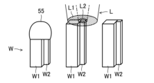
図4Bに示すように、第1部材W1に高出力の第1レーザ光L1を出射し、第2部材W2に低出力の第2レーザ光L2を出射することで、第1部材W1及び第2部材W2の上端部が溶融して、接合部55が形成される。第1部材W1及び第2部材W2は、接合部55を介して接合される。
As shown in FIG. 4B, by emitting a high-power first laser beam L1 to the first member W1 and emitting a low-power second laser beam L2 to the second member W2, the first member W1 and the second laser beam L2 are irradiated. The upper end of the member W2 is melted to form the joint 55. As shown in FIG. The first member W<b>1 and the second member W<b>2 are joined via the joining portion 55 .
ここで、熱容量の大きい第1部材W1に対して、高出力の第1レーザ光L1を出射する一方、熱容量の小さい第2部材W2に対して、低出力の第2レーザ光L2を出射している。これにより、第1部材W1及び第2部材W2の溶融タイミングを合わせて、熱容量の小さな第2部材W2が先に溶け落ちてしまうのを抑えることができる。
Here, a high-output first laser beam L1 is emitted to the first member W1 having a large heat capacity, while a low-output second laser beam L2 is emitted to the second member W2 having a small heat capacity. there is As a result, the melting timings of the first member W1 and the second member W2 can be matched to prevent the second member W2 having a small heat capacity from being melted down first.
なお、第1工程及び第2工程の実行中に、第1部材W1及び第2部材W2の溶融状態に応じて、第1レーザ光L1及び第2レーザ光L2の出力の比率を変更するようにしてもよい。
During execution of the first step and the second step, the output ratio of the first laser beam L1 and the second laser beam L2 is changed according to the molten state of the first member W1 and the second member W2. may
例えば、第1部材W1及び第2部材W2が溶融して一部が接合されたときに、第1レーザ光L1がレーザ光Lの50%の出力となり、第2レーザ光L2がレーザ光Lの50%の出力となるように、伝送ファイバ40に対するレーザ光Lの入射位置を調整してもよい。これにより、レーザ光Lのビームプロファイルを、いわゆるトップハット形状に変更して、接合部55の形状をきれいにすることができる。
For example, when the first member W1 and the second member W2 are melted and partially joined, the output of the first laser beam L1 is 50% of the output of the laser beam L, and the output of the second laser beam L2 is that of the laser beam L. The incident position of the laser light L with respect to the transmission fiber 40 may be adjusted so that the output is 50%. Thereby, the beam profile of the laser light L can be changed into a so-called top hat shape, and the shape of the joint 55 can be made clean.
レーザ加工ヘッド50は、図4Bで左から1番目のワークWをレーザ溶接した後、2番目のワークWの上方位置まで移動する。レーザ加工ヘッド50は、2番目のワークWの第1部材W1及び第2部材W2に対して、第1レーザ光L1及び第2レーザ光L2を出射する。
After laser welding the first work W from the left in FIG. 4B, the laser processing head 50 moves to a position above the second work W. The laser processing head 50 emits the first laser beam L1 and the second laser beam L2 to the first member W1 and the second member W2 of the second workpiece W. As shown in FIG.
図4Cに示すように、2番目の第1部材W1及び第2部材W2の上端部が溶融して、接合部55が形成される。第1部材W1及び第2部材W2は、接合部55を介して接合される。レーザ加工ヘッド50は、2番目のワークWをレーザ溶接した後、3番目のワークWの上方位置まで移動する。レーザ加工ヘッド50は、3番目のワークWの第1部材W1及び第2部材W2に対して、第1レーザ光L1及び第2レーザ光L2を出射する。
As shown in FIG. 4C, the upper ends of the second first member W1 and second member W2 are melted to form a joint 55. As shown in FIG. The first member W<b>1 and the second member W<b>2 are joined via the joining portion 55 . After laser welding the second work W, the laser processing head 50 moves to a position above the third work W. As shown in FIG. The laser processing head 50 emits the first laser beam L1 and the second laser beam L2 to the first member W1 and the second member W2 of the third workpiece W. As shown in FIG.
このように、第1部材W1及び第2部材W2の溶融タイミングを合わせた制御を行うことで、1番目のワークWの接合部55の形状と、2番目のワークWの接合部55の形状とが略同じ形状となりやすい。その結果、第1部材W1及び第2部材W2の接合部55の形状が安定するので、接合強度がばらつくのを抑えることができる。
By controlling the melting timings of the first member W1 and the second member W2 in this manner, the shape of the joint portion 55 of the first work W and the shape of the joint portion 55 of the second work W can be changed. tend to have substantially the same shape. As a result, the shape of the joint portion 55 between the first member W1 and the second member W2 is stabilized, so that variations in joint strength can be suppressed.
以下、比較例として、第1部材W1及び第2部材W2の溶融タイミングが不一致となる条件下でレーザ溶接を行った場合について説明する。
Hereinafter, as a comparative example, a case where laser welding is performed under conditions in which the melting timings of the first member W1 and the second member W2 do not match will be described.
図5Aに示す比較例では、伝送ファイバ40は、シングルコアファイバを用いる。伝送ファイバ40は、第1コア41と、第1クラッド43と、保護皮膜45とを有する。レーザ光Lは、第1コア41に入射される。
In the comparative example shown in FIG. 5A, the transmission fiber 40 uses a single core fiber. The transmission fiber 40 has a first core 41 , a first clad 43 and a protective coating 45 . A laser beam L is incident on the first core 41 .
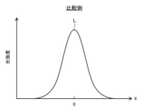
図5Bに示すように、レーザ光Lのビームプロファイルは、第1コア41の軸心に対応するX=0となる位置を中心とした単峰状のガウシアン分布となる。
As shown in FIG. 5B, the beam profile of the laser light L has a unimodal Gaussian distribution centered on the position where X=0 corresponding to the axial center of the first core 41 .
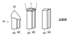
図6Aに示すように、レーザ加工ヘッド50は、ワークWの第1部材W1及び第2部材W2に対してレーザ光Lを出射する。ここで、第1部材W1及び第2部材W2に出射されるレーザ光Lの出力が同じであるため、熱容量の小さい第2部材W2が、熱容量の大きい第1部材W1よりも先に溶融することとなる。
As shown in FIG. 6A, the laser processing head 50 emits laser light L to the first member W1 and the second member W2 of the workpiece W. As shown in FIG. Here, since the output of the laser light L emitted to the first member W1 and the second member W2 is the same, the second member W2 having a smaller heat capacity melts earlier than the first member W1 having a larger heat capacity. becomes.
そのため、図6Bに示すように、第1部材W1及び第2部材W2の接合部55は、第2部材W2の溶融量が大きく、第2部材W2側に大きく傾斜した形状となる。
Therefore, as shown in FIG. 6B, the joint portion 55 between the first member W1 and the second member W2 has a large melting amount of the second member W2 and has a shape greatly inclined toward the second member W2 side.
また、図6Cに示すように、2番目のワークWに対してレーザ光Lを出射した場合、第1部材W1及び第2部材W2の溶融量が安定しないことから、1番目の接合部55の形状と、2番目の接合部55の形状とが、異なった形状となりやすい。このように、接合部55の形状が不安定となると、接合部55の接合強度がばらつくため、好ましくない。
Further, as shown in FIG. 6C, when the laser beam L is emitted to the second workpiece W, the melting amount of the first member W1 and the second member W2 is not stable, so the first joint portion 55 The shape and the shape of the second joint portion 55 are likely to be different shapes. If the shape of the joint 55 becomes unstable in this manner, the joint strength of the joint 55 varies, which is not preferable.
以上のように、本実施形態に係るレーザ溶接装置1によれば、第1部材W1及び第2部材W2の溶融タイミングを合わせて、熱容量の小さな第2部材W2が先に溶け落ちてしまうのを抑えることができる。その結果、第1部材W1及び第2部材W2の接合形状が安定するので、接合強度がばらつくのを抑えることができる。
As described above, according to the laser welding apparatus 1 according to the present embodiment, the melting timings of the first member W1 and the second member W2 are matched to prevent the second member W2 having a small heat capacity from being melted down first. can be suppressed. As a result, since the joint shape of the first member W1 and the second member W2 is stabilized, variations in joint strength can be suppressed.
《実施形態2》
以下、前記実施形態1と同じ部分については同じ符号を付し、相違点についてのみ説明する。 <<Embodiment 2>>
In the following, the same reference numerals are given to the same parts as in the first embodiment, and only the points of difference will be described.
以下、前記実施形態1と同じ部分については同じ符号を付し、相違点についてのみ説明する。 <<Embodiment 2>>
In the following, the same reference numerals are given to the same parts as in the first embodiment, and only the points of difference will be described.
図7Aに示すように、レーザ光Lは、第1コア41と第2コア42とに跨って入射される。レーザ光Lは、第1コア41よりも第2コア42寄りの位置に入射される。第2コア42に入射されるレーザ光Lの光量は、第1コア41に入射されるレーザ光Lの光量よりも多くなる。レーザ光Lは、第2コア42に入射される第1レーザ光L1と、第1コア41に入射される第2レーザ光L2とに分配される。
As shown in FIG. 7A, the laser light L is incident across the first core 41 and the second core 42 . The laser light L is incident on a position closer to the second core 42 than the first core 41 is. The amount of laser light L incident on the second core 42 is greater than the amount of laser light L incident on the first core 41 . The laser beam L is divided into a first laser beam L1 incident on the second core 42 and a second laser beam L2 incident on the first core 41 .
図7Aに示す例では、第2レーザ光L2がレーザ光Lの30%の出力となり、第1レーザ光L1がレーザ光Lの70%の出力となるように、伝送ファイバ40に対するレーザ光Lの入射位置を調整する。
In the example shown in FIG. 7A, the output of the second laser beam L2 is 30% of the output of the laser beam L, and the output of the first laser beam L1 is 70% of the output of the laser beam L. Adjust the incident position.
図7Bに示すように、レーザ光Lのビームプロファイルは、第1コア41の軸心に対応するX=0となる中央位置と、X=0となる位置を挟んで第2コア42に対応する位置とに、それぞれピークが現れる形状となる。
As shown in FIG. 7B, the beam profile of the laser light L corresponds to the central position where X=0 corresponding to the axial center of the first core 41 and the second core 42 across the position where X=0. It becomes a shape in which a peak appears at each position.
実際には、中央の単峰状のピークと、中央のピークの周囲に沿ってXY平面上にリング状のピークを有する分布となる。ここで、中央のピークは、リング状のピークよりも小さい。
In reality, the distribution has a central unimodal peak and a ring-shaped peak on the XY plane along the circumference of the central peak. Here, the central peak is smaller than the ring-shaped peak.
図8Aに示すように、第1工程では、レーザ加工ヘッド50は、第1部材W1に対して、第2コア42からリング状の第1レーザ光L1を出射する。
As shown in FIG. 8A, in the first step, the laser processing head 50 emits the ring-shaped first laser beam L1 from the second core 42 to the first member W1.
第2工程では、レーザ加工ヘッド50は、第1工程の実行中に、第2部材W2に対して、第1コア41から円形状の第2レーザ光L2を出射する。第2部材W2は、第1部材W1よりも熱容量が小さい。第2レーザ光L2は、第1レーザ光L1よりも出力が低い。
In the second step, the laser processing head 50 emits a circular second laser beam L2 from the first core 41 to the second member W2 during execution of the first step. The second member W2 has a smaller heat capacity than the first member W1. The output of the second laser beam L2 is lower than that of the first laser beam L1.
図8Bに示すように、第1部材W1に高出力の第1レーザ光L1を出射し、第2部材W2に低出力の第2レーザ光L2を出射することで、第1部材W1及び第2部材W2の上端部が溶融して、接合部55が形成される。第1部材W1及び第2部材W2は、接合部55を介して接合される。
As shown in FIG. 8B, by emitting a high-power first laser beam L1 to the first member W1 and emitting a low-power second laser beam L2 to the second member W2, the first member W1 and the second laser beam L2 are irradiated. The upper end of the member W2 is melted to form the joint 55. As shown in FIG. The first member W<b>1 and the second member W<b>2 are joined via the joining portion 55 .
レーザ加工ヘッド50は、図8Bで左から1番目のワークWをレーザ溶接した後、2番目のワークWの上方位置まで移動する。レーザ加工ヘッド50は、2番目のワークWの第1部材W1及び第2部材W2に対して、第1レーザ光L1及び第2レーザ光L2を出射する。
After laser welding the first work W from the left in FIG. 8B, the laser processing head 50 moves to a position above the second work W. The laser processing head 50 emits the first laser beam L1 and the second laser beam L2 to the first member W1 and the second member W2 of the second workpiece W. As shown in FIG.
図8Cに示すように、2番目の第1部材W1及び第2部材W2の上端部が溶融して、接合部55が形成される。第1部材W1及び第2部材W2は、接合部55を介して接合される。
As shown in FIG. 8C, the upper ends of the second first member W1 and second member W2 are melted to form a joint 55. As shown in FIG. The first member W<b>1 and the second member W<b>2 are joined via the joining portion 55 .
ここで、本実施形態のように、第1部材W1及び第2部材W2の溶融タイミングを合わせた制御を行うことで、1番目のワークWの接合部55の形状と、2番目のワークWの接合部55の形状とが略同じ形状となりやすい。その結果、第1部材W1及び第2部材W2の接合部55の形状が安定するので、接合強度がばらつくのを抑えることができる。
Here, as in the present embodiment, by performing control in which the melting timings of the first member W1 and the second member W2 are matched, the shape of the joint portion 55 of the first work W and the shape of the second work W can be changed. The shape is likely to be substantially the same as the shape of the joint portion 55 . As a result, the shape of the joint portion 55 between the first member W1 and the second member W2 is stabilized, so that variations in joint strength can be suppressed.
《変形例》
本実施形態では、1つのレーザ発振器10から出射されたレーザ光Lを、第1コア41と第2コア42とに適切な比率で分配することで、第1レーザ光L1及び第2レーザ光L2の出力を変更するようにしたが、この形態に限定するものではない。 <<Modification>>
In this embodiment, by distributing the laser light L emitted from onelaser oscillator 10 to the first core 41 and the second core 42 at an appropriate ratio, the first laser light L1 and the second laser light L2 Although the output of is changed, it is not limited to this form.
本実施形態では、1つのレーザ発振器10から出射されたレーザ光Lを、第1コア41と第2コア42とに適切な比率で分配することで、第1レーザ光L1及び第2レーザ光L2の出力を変更するようにしたが、この形態に限定するものではない。 <<Modification>>
In this embodiment, by distributing the laser light L emitted from one
図9に示すように、光結合ユニット20は、第1レーザ発振器81と、第2レーザ発振器82と、第1ミラー83と、第2ミラー84と、第1調整機構85と、第2調整機構86とを有する。
As shown in FIG. 9, the optical coupling unit 20 includes a first laser oscillator 81, a second laser oscillator 82, a first mirror 83, a second mirror 84, a first adjusting mechanism 85, and a second adjusting mechanism. 86.
第1レーザ発振器81は、レーザ制御部74からの指令に基づいて、第1レーザ光L1を出射する。第2レーザ発振器82は、レーザ制御部74からの指令に基づいて、第2レーザ光L2を出射する。第2レーザ光L2は、第1レーザ光L1よりも出力が低い。
The first laser oscillator 81 emits a first laser beam L1 based on a command from the laser control section 74. The second laser oscillator 82 emits the second laser light L2 based on a command from the laser control section 74. As shown in FIG. The output of the second laser beam L2 is lower than that of the first laser beam L1.
第1ミラー83は、第1レーザ発振器81から出射された第1レーザ光L1を反射して、第1調整機構85に導光する。
The first mirror 83 reflects the first laser beam L1 emitted from the first laser oscillator 81 and guides it to the first adjusting mechanism 85 .
第2ミラー84は、第2レーザ発振器82から出射された第2レーザ光L2を反射して、第2調整機構86に導光する。
The second mirror 84 reflects the second laser beam L2 emitted from the second laser oscillator 82 and guides it to the second adjustment mechanism 86 .
第1調整機構85は、例えば、2軸方向に角度変更可能な2軸MEMS(Micro Electro Mechanical Systems)ミラーで構成される。第1調整機構85は、第1ミラー83で反射された第1レーザ光L1をさらに反射して、伝送ファイバ40に導光する。第1調整機構85は、ミラーの角度を2軸方向に変更することで、伝送ファイバ40に対する第1レーザ光L1の入射位置を変更する。これにより、第1レーザ光L1を、伝送ファイバ40の第1コア41又は第2コア42に対して選択的に入射可能となっている。図9に示す例では、第1レーザ光L1は、第1コア41に入射される。図10に示す例では、第1レーザ光L1は、第2コア42に入射される。
The first adjustment mechanism 85 is composed of, for example, a biaxial MEMS (Micro Electro Mechanical Systems) mirror whose angle can be changed in biaxial directions. The first adjustment mechanism 85 further reflects the first laser beam L<b>1 reflected by the first mirror 83 and guides it to the transmission fiber 40 . The first adjustment mechanism 85 changes the incident position of the first laser beam L1 with respect to the transmission fiber 40 by changing the angle of the mirror in two axial directions. This allows the first laser beam L1 to selectively enter the first core 41 or the second core 42 of the transmission fiber 40 . In the example shown in FIG. 9 , the first laser beam L1 is incident on the first core 41 . In the example shown in FIG. 10 , the first laser beam L1 is incident on the second core 42 .
第2調整機構86は、例えば、2軸方向に角度変更可能な2軸MEMSミラー(Micro Electro Mechanical Systems)で構成される。第2調整機構86は、第2ミラー84で反射された第2レーザ光L2をさらに反射して、伝送ファイバ40に導光する。第2調整機構86は、ミラーの角度を2軸方向に変更することで、伝送ファイバ40に対する第2レーザ光L2の入射位置を変更する。これにより、第2レーザ光L2を、伝送ファイバ40の第1コア41又は第2コア42に対して選択的に入射可能となっている。図9に示す例では、第2レーザ光L2は、第2コア42に入射される。図10に示す例では、第2レーザ光L2は、第1コア41に入射される。
The second adjustment mechanism 86 is composed of, for example, a biaxial MEMS mirror (Micro Electro Mechanical Systems) whose angle can be changed in biaxial directions. The second adjustment mechanism 86 further reflects the second laser beam L2 reflected by the second mirror 84 and guides it to the transmission fiber 40 . The second adjustment mechanism 86 changes the incident position of the second laser beam L2 with respect to the transmission fiber 40 by changing the angle of the mirror in two axial directions. This allows the second laser beam L2 to selectively enter the first core 41 or the second core 42 of the transmission fiber 40 . In the example shown in FIG. 9 , the second laser beam L2 is incident on the second core 42 . In the example shown in FIG. 10 , the second laser beam L2 is incident on the first core 41 .
なお、第1調整機構85及び第2調整機構86は、2軸MEMSミラーの代わりに、2軸のガルバノメータ(ガルバノミラー)を用いた構成としてもよい。また、第1調整機構85及び第2調整機構86は、上述した実施形態の光路変更機構23で構成してもよい。
Note that the first adjustment mechanism 85 and the second adjustment mechanism 86 may be configured using a biaxial galvanometer (galvanomirror) instead of the biaxial MEMS mirror. Also, the first adjusting mechanism 85 and the second adjusting mechanism 86 may be configured by the optical path changing mechanism 23 of the above-described embodiment.
なお、本変形例では、第1レーザ光L1と第2レーザ光L2とが、同じ波長である場合について説明したが、この形態に限定するものではなく、第1レーザ光L1と第2レーザ光L2とが、互いに波長が異なっていてもよい。
In this modified example, the case where the first laser beam L1 and the second laser beam L2 have the same wavelength has been described. and L2 may have different wavelengths.
例えば、第1レーザ光L1は、第2レーザ光L2よりも波長の短い短波長のレーザ光であってもよい。この場合、短波長の第1レーザ光L1は、波長が600nm以下(例えば、266nm~600nm)の青色レーザ光又は緑色レーザ光レーザ光とすればよい。また、長波長の第2レーザ光L2は、波長が800nm以上(例えば、800nm~16000nm程度)の赤外レーザ光とすればよい。
For example, the first laser beam L1 may be a short-wavelength laser beam having a shorter wavelength than the second laser beam L2. In this case, the short-wavelength first laser light L1 may be blue laser light or green laser light laser light with a wavelength of 600 nm or less (for example, 266 nm to 600 nm). Further, the long-wavelength second laser light L2 may be infrared laser light with a wavelength of 800 nm or more (for example, about 800 nm to 16000 nm).
これにより、第1部材W1又は第2部材W2が、例えば、レーザ光の反射率が鉄(Fe)などに比べて相対的に高い高反射材料である銅(Cu)、金(Au)、銀(Ag)などで構成されている場合に、高反射材料に吸収されやすい短波長のレーザ光を高反射材料に対して出射することで、高反射材料を溶融させやすくなる。
As a result, the first member W1 or the second member W2 is made of, for example, copper (Cu), gold (Au), or silver, which is a highly reflective material having a relatively high laser light reflectance compared to iron (Fe). When it is composed of (Ag) or the like, the highly reflective material is easily melted by emitting a short-wavelength laser beam, which is easily absorbed by the highly reflective material, to the highly reflective material.
《その他の実施形態》
前記実施形態については、以下のような構成としてもよい。 <<Other embodiments>>
The above embodiment may be configured as follows.
前記実施形態については、以下のような構成としてもよい。 <<Other embodiments>>
The above embodiment may be configured as follows.
本実施形態では、第1工程の前に、第1部材W1及び第2部材W2に対してレーザ光Lをそれぞれ出射して、第1部材W1及び第2部材W2を予熱する工程を行うようにしてもよい。
In this embodiment, before the first step, a step of preheating the first member W1 and the second member W2 by emitting the laser light L to the first member W1 and the second member W2 is performed. may
このように、第1部材W1及び第2部材W2をそれぞれ予熱することで、第1工程及び第2工程において、第1部材W1及び第2部材W2を溶融させやすくなる。
By preheating the first member W1 and the second member W2 in this manner, the first member W1 and the second member W2 can be easily melted in the first step and the second step.
また、本実施形態では、第1工程の前に、第1部材W1及び第2部材W2の溶接箇所におけるレーザ光Lのスポット径を調整する工程を行うようにしてもよい。
Also, in the present embodiment, a step of adjusting the spot diameter of the laser beam L at the welded portion of the first member W1 and the second member W2 may be performed before the first step.
このように、レーザ光Lをデフォーカスして、第1部材W1及び第2部材W2の溶接箇所をレーザ光Lのスポット径の範囲内に収めることで、溶接箇所の全範囲にレーザ光Lを出射することができる。
In this way, by defocusing the laser beam L and keeping the welding points of the first member W1 and the second member W2 within the range of the spot diameter of the laser beam L, the laser beam L can be applied to the entire range of the welding points. can be emitted.
また、レーザ光Lのスポット径を適切に調整することで、第1部材W1及び第2部材W2の溶接箇所よりも外方にレーザ光Lが漏れるのを抑えることができる。
Also, by appropriately adjusting the spot diameter of the laser beam L, it is possible to suppress the leakage of the laser beam L to the outside of the welded portions of the first member W1 and the second member W2.
以上説明したように、本発明は、熱容量の異なる第1部材及び第2部材の接合強度がばらつくのを抑えることができるという実用性の高い効果が得られることから、きわめて有用で産業上の利用可能性は高い。
INDUSTRIAL APPLICABILITY As described above, the present invention has a highly practical effect of suppressing variations in bonding strength between the first member and the second member having different heat capacities, and is therefore extremely useful and industrially applicable. Very likely.
1 レーザ溶接装置
10 レーザ発振器
20 光結合ユニット
23 光路変更機構
40 伝送ファイバ
41 第1コア
42 第2コア
50 レーザ加工ヘッド
52 集光レンズ
71 光路制御部
73 マニピュレータ制御部
74 レーザ制御部
81 第1レーザ発振器
82 第2レーザ発振器
85 第1調整機構
86 第2調整機構
L レーザ光
L1 第1レーザ光
L2 第2レーザ光
W1 第1部材
W2 第2部材 Reference Signs List 1laser welding device 10 laser oscillator 20 optical coupling unit 23 optical path changing mechanism 40 transmission fiber 41 first core 42 second core 50 laser processing head 52 condenser lens 71 optical path controller 73 manipulator controller 74 laser controller 81 first laser Oscillator 82 Second laser oscillator 85 First adjustment mechanism 86 Second adjustment mechanism L Laser light L1 First laser light L2 Second laser light W1 First member W2 Second member
10 レーザ発振器
20 光結合ユニット
23 光路変更機構
40 伝送ファイバ
41 第1コア
42 第2コア
50 レーザ加工ヘッド
52 集光レンズ
71 光路制御部
73 マニピュレータ制御部
74 レーザ制御部
81 第1レーザ発振器
82 第2レーザ発振器
85 第1調整機構
86 第2調整機構
L レーザ光
L1 第1レーザ光
L2 第2レーザ光
W1 第1部材
W2 第2部材 Reference Signs List 1
Claims (8)
- 伝送ファイバで伝送されたレーザ光を出射して、第1部材と、該第1部材よりも熱容量が小さい第2部材とを溶接するレーザ溶接方法であって、
前記伝送ファイバは、第1コアと、該第1コアの外周部に設けられた第2コアとを有し、
前記第1部材に対して、前記第1コア又は前記第2コアの一方から第1レーザ光を出射する第1工程と、
前記第1工程の実行中に、前記第2部材に対して、前記第1コア又は前記第2コアの他方から前記第1レーザ光よりも出力の低い第2レーザ光を出射する第2工程とを備えた
ことを特徴とするレーザ溶接方法。 A laser welding method for emitting a laser beam transmitted by a transmission fiber to weld a first member and a second member having a smaller heat capacity than the first member,
The transmission fiber has a first core and a second core provided on the outer circumference of the first core,
a first step of emitting a first laser beam from one of the first core and the second core to the first member;
a second step of emitting a second laser beam having a lower output than the first laser beam to the second member from the other of the first core and the second core during the execution of the first step; A laser welding method comprising: - 請求項1において、
前記第1工程及び前記第2工程では、前記第1コア及び前記第2コアに入射される前記レーザ光の比率を変更することで、前記第1レーザ光及び前記第2レーザ光の出力を変更する
ことを特徴とするレーザ溶接方法。 In claim 1,
In the first step and the second step, the outputs of the first laser light and the second laser light are changed by changing the ratio of the laser light incident on the first core and the second core. A laser welding method characterized by: - 請求項1又は2において、
前記第1工程では、前記第1コアから前記第1レーザ光を出射させ、
前記第2工程では、前記第2コアから前記第2レーザ光を出射させる
ことを特徴とするレーザ溶接方法。 In claim 1 or 2,
In the first step, the first laser beam is emitted from the first core,
The laser welding method, wherein in the second step, the second laser beam is emitted from the second core. - 請求項1又は2において、
前記第1工程では、前記第2コアから前記第1レーザ光を出射させ、
前記第2工程では、前記第1コアから前記第2レーザ光を出射させる
ことを特徴とするレーザ溶接方法。 In claim 1 or 2,
In the first step, the first laser beam is emitted from the second core,
The laser welding method, wherein in the second step, the second laser beam is emitted from the first core. - 請求項1乃至4のうち何れか1つにおいて、
前記第1工程の前に、前記第1部材及び前記第2部材に対して前記レーザ光をそれぞれ出射して、該第1部材及び該第2部材を予熱する工程を備えた
ことを特徴とするレーザ溶接方法。 In any one of claims 1 to 4,
A step of preheating the first member and the second member by emitting the laser beams to the first member and the second member, respectively, before the first step. laser welding method. - 請求項1乃至5のうち何れか1つにおいて、
前記第1工程の前に、前記第1部材及び前記第2部材の溶接箇所における前記レーザ光のスポット径を調整する工程を備えた
ことを特徴とするレーザ溶接方法。 In any one of claims 1 to 5,
A laser welding method, comprising, before the first step, adjusting a spot diameter of the laser beam at a welded portion of the first member and the second member. - 請求項1乃至6のうち何れか1つにおいて、
前記第1レーザ光及び前記第2レーザ光は、互いに波長が異なる
ことを特徴とするレーザ溶接方法。 In any one of claims 1 to 6,
The laser welding method, wherein the first laser beam and the second laser beam have different wavelengths. - 請求項1乃至7のうち何れか1つにおいて、
前記第1工程及び前記第2工程の実行中に、前記第1レーザ光及び前記第2レーザ光のうち少なくとも一方の出力を調整する工程を備えた
ことを特徴とするレーザ溶接方法。 In any one of claims 1 to 7,
A laser welding method, comprising: adjusting the output of at least one of the first laser beam and the second laser beam during execution of the first step and the second step.
Applications Claiming Priority (2)
| Application Number | Priority Date | Filing Date | Title |
|---|---|---|---|
| JP2022-014617 | 2022-02-02 | ||
| JP2022014617 | 2022-02-02 |
Publications (1)
| Publication Number | Publication Date |
|---|---|
| WO2023149452A1 true WO2023149452A1 (en) | 2023-08-10 |
Family
ID=87552445
Family Applications (1)
| Application Number | Title | Priority Date | Filing Date |
|---|---|---|---|
| PCT/JP2023/003156 WO2023149452A1 (en) | 2022-02-02 | 2023-02-01 | Laser welding method |
Country Status (1)
| Country | Link |
|---|---|
| WO (1) | WO2023149452A1 (en) |
Citations (5)
| Publication number | Priority date | Publication date | Assignee | Title |
|---|---|---|---|---|
| JP2001047272A (en) * | 1999-08-05 | 2001-02-20 | Sumitomo Heavy Ind Ltd | Method for laser beam welding |
| JP2018144091A (en) * | 2017-03-08 | 2018-09-20 | プライムアースEvエナジー株式会社 | Laser welding apparatus, laser welding method, and laser processing lens |
| WO2019176502A1 (en) * | 2018-03-15 | 2019-09-19 | パナソニックIpマネジメント株式会社 | Laser oscillator, laser machining device in which same is used, and laser oscillation method |
| JP2020190689A (en) * | 2019-05-23 | 2020-11-26 | 三菱重工業株式会社 | Transmission fiber, laser machining device and laser transmission method |
| JP2021104518A (en) * | 2019-12-26 | 2021-07-26 | パナソニックIpマネジメント株式会社 | Laser processing device and laser processing method |
-
2023
- 2023-02-01 WO PCT/JP2023/003156 patent/WO2023149452A1/en unknown
Patent Citations (5)
| Publication number | Priority date | Publication date | Assignee | Title |
|---|---|---|---|---|
| JP2001047272A (en) * | 1999-08-05 | 2001-02-20 | Sumitomo Heavy Ind Ltd | Method for laser beam welding |
| JP2018144091A (en) * | 2017-03-08 | 2018-09-20 | プライムアースEvエナジー株式会社 | Laser welding apparatus, laser welding method, and laser processing lens |
| WO2019176502A1 (en) * | 2018-03-15 | 2019-09-19 | パナソニックIpマネジメント株式会社 | Laser oscillator, laser machining device in which same is used, and laser oscillation method |
| JP2020190689A (en) * | 2019-05-23 | 2020-11-26 | 三菱重工業株式会社 | Transmission fiber, laser machining device and laser transmission method |
| JP2021104518A (en) * | 2019-12-26 | 2021-07-26 | パナソニックIpマネジメント株式会社 | Laser processing device and laser processing method |
Similar Documents
| Publication | Publication Date | Title |
|---|---|---|
| US11364572B2 (en) | Laser cutting head with dual movable mirrors providing beam alignment and/or wobbling movement | |
| JP6602860B2 (en) | Laser processing apparatus and laser processing method | |
| JP4988160B2 (en) | Laser welding apparatus, laser welding system, and laser welding method | |
| CN101309776A (en) | Method and apparatus in connection with laser use | |
| CN101439441A (en) | Optical fiber laser dynamic focusing vibration mirror scanning type spot welding system and welding method thereof | |
| JP2012110905A (en) | Method and apparatus for welding | |
| US20060226128A1 (en) | Laser welding method and laser welding robot | |
| JP2003001452A (en) | Laser welding method and semiconductor laser module manufactured by using the method | |
| JP2000042779A (en) | Laser beam machining device | |
| US4733047A (en) | Spot welding technique | |
| WO2023149452A1 (en) | Laser welding method | |
| WO2021145358A1 (en) | Laser processing device | |
| CN113102781A (en) | Three-beam wire powder mixed laser cladding system | |
| CN211564832U (en) | SLM double-laser composite processing device | |
| US20220088709A1 (en) | Laser welding device and laser welding method using same | |
| KR20120114651A (en) | Laser welding machine adjustable position of laser focus and identifiable welding faulty | |
| WO2023149451A1 (en) | Laser processing method | |
| JP2023112735A (en) | Laser weld method | |
| WO2023149449A1 (en) | Laser processing method | |
| WO2023149453A1 (en) | Laser machining apparatus | |
| JP2023112736A (en) | Laser processor | |
| JP2023112734A (en) | Laser machining method | |
| US20220334367A1 (en) | Laser device, and laser processing device in which same is used | |
| US20220371122A1 (en) | Laser processing apparatus | |
| WO2021107043A1 (en) | Laser processing device |
Legal Events
| Date | Code | Title | Description |
|---|---|---|---|
| 121 | Ep: the epo has been informed by wipo that ep was designated in this application |
Ref document number: 23749768 Country of ref document: EP Kind code of ref document: A1 |