WO2023145470A1 - ガス検知システム及びガス検知方法 - Google Patents
ガス検知システム及びガス検知方法 Download PDFInfo
- Publication number
- WO2023145470A1 WO2023145470A1 PCT/JP2023/000636 JP2023000636W WO2023145470A1 WO 2023145470 A1 WO2023145470 A1 WO 2023145470A1 JP 2023000636 W JP2023000636 W JP 2023000636W WO 2023145470 A1 WO2023145470 A1 WO 2023145470A1
- Authority
- WO
- WIPO (PCT)
- Prior art keywords
- gas
- valve
- hydrogen
- pressure
- detector
- Prior art date
- Legal status (The legal status is an assumption and is not a legal conclusion. Google has not performed a legal analysis and makes no representation as to the accuracy of the status listed.)
- Ceased
Links
Images




Classifications
-
- F—MECHANICAL ENGINEERING; LIGHTING; HEATING; WEAPONS; BLASTING
- F17—STORING OR DISTRIBUTING GASES OR LIQUIDS
- F17C—VESSELS FOR CONTAINING OR STORING COMPRESSED, LIQUEFIED OR SOLIDIFIED GASES; FIXED-CAPACITY GAS-HOLDERS; FILLING VESSELS WITH, OR DISCHARGING FROM VESSELS, COMPRESSED, LIQUEFIED, OR SOLIDIFIED GASES
- F17C13/00—Details of vessels or of the filling or discharging of vessels
- F17C13/02—Special adaptations of indicating, measuring, or monitoring equipment
-
- H—ELECTRICITY
- H01—ELECTRIC ELEMENTS
- H01M—PROCESSES OR MEANS, e.g. BATTERIES, FOR THE DIRECT CONVERSION OF CHEMICAL ENERGY INTO ELECTRICAL ENERGY
- H01M8/00—Fuel cells; Manufacture thereof
-
- H—ELECTRICITY
- H01—ELECTRIC ELEMENTS
- H01M—PROCESSES OR MEANS, e.g. BATTERIES, FOR THE DIRECT CONVERSION OF CHEMICAL ENERGY INTO ELECTRICAL ENERGY
- H01M8/00—Fuel cells; Manufacture thereof
- H01M8/04—Auxiliary arrangements, e.g. for control of pressure or for circulation of fluids
-
- H—ELECTRICITY
- H01—ELECTRIC ELEMENTS
- H01M—PROCESSES OR MEANS, e.g. BATTERIES, FOR THE DIRECT CONVERSION OF CHEMICAL ENERGY INTO ELECTRICAL ENERGY
- H01M8/00—Fuel cells; Manufacture thereof
- H01M8/04—Auxiliary arrangements, e.g. for control of pressure or for circulation of fluids
- H01M8/04082—Arrangements for control of reactant parameters, e.g. pressure or concentration
- H01M8/04089—Arrangements for control of reactant parameters, e.g. pressure or concentration of gaseous reactants
-
- H—ELECTRICITY
- H01—ELECTRIC ELEMENTS
- H01M—PROCESSES OR MEANS, e.g. BATTERIES, FOR THE DIRECT CONVERSION OF CHEMICAL ENERGY INTO ELECTRICAL ENERGY
- H01M8/00—Fuel cells; Manufacture thereof
- H01M8/04—Auxiliary arrangements, e.g. for control of pressure or for circulation of fluids
- H01M8/04082—Arrangements for control of reactant parameters, e.g. pressure or concentration
- H01M8/04201—Reactant storage and supply, e.g. means for feeding, pipes
-
- H—ELECTRICITY
- H01—ELECTRIC ELEMENTS
- H01M—PROCESSES OR MEANS, e.g. BATTERIES, FOR THE DIRECT CONVERSION OF CHEMICAL ENERGY INTO ELECTRICAL ENERGY
- H01M8/00—Fuel cells; Manufacture thereof
- H01M8/04—Auxiliary arrangements, e.g. for control of pressure or for circulation of fluids
- H01M8/04298—Processes for controlling fuel cells or fuel cell systems
- H01M8/04313—Processes for controlling fuel cells or fuel cell systems characterised by the detection or assessment of variables; characterised by the detection or assessment of failure or abnormal function
- H01M8/0438—Pressure; Ambient pressure; Flow
-
- H—ELECTRICITY
- H01—ELECTRIC ELEMENTS
- H01M—PROCESSES OR MEANS, e.g. BATTERIES, FOR THE DIRECT CONVERSION OF CHEMICAL ENERGY INTO ELECTRICAL ENERGY
- H01M8/00—Fuel cells; Manufacture thereof
- H01M8/04—Auxiliary arrangements, e.g. for control of pressure or for circulation of fluids
- H01M8/04298—Processes for controlling fuel cells or fuel cell systems
- H01M8/04694—Processes for controlling fuel cells or fuel cell systems characterised by variables to be controlled
-
- H—ELECTRICITY
- H01—ELECTRIC ELEMENTS
- H01M—PROCESSES OR MEANS, e.g. BATTERIES, FOR THE DIRECT CONVERSION OF CHEMICAL ENERGY INTO ELECTRICAL ENERGY
- H01M8/00—Fuel cells; Manufacture thereof
- H01M8/04—Auxiliary arrangements, e.g. for control of pressure or for circulation of fluids
- H01M8/04298—Processes for controlling fuel cells or fuel cell systems
- H01M8/04694—Processes for controlling fuel cells or fuel cell systems characterised by variables to be controlled
- H01M8/04746—Pressure; Flow
-
- H—ELECTRICITY
- H01—ELECTRIC ELEMENTS
- H01M—PROCESSES OR MEANS, e.g. BATTERIES, FOR THE DIRECT CONVERSION OF CHEMICAL ENERGY INTO ELECTRICAL ENERGY
- H01M8/00—Fuel cells; Manufacture thereof
- H01M8/04—Auxiliary arrangements, e.g. for control of pressure or for circulation of fluids
- H01M8/04298—Processes for controlling fuel cells or fuel cell systems
- H01M8/04694—Processes for controlling fuel cells or fuel cell systems characterised by variables to be controlled
- H01M8/04791—Concentration; Density
-
- F—MECHANICAL ENGINEERING; LIGHTING; HEATING; WEAPONS; BLASTING
- F17—STORING OR DISTRIBUTING GASES OR LIQUIDS
- F17C—VESSELS FOR CONTAINING OR STORING COMPRESSED, LIQUEFIED OR SOLIDIFIED GASES; FIXED-CAPACITY GAS-HOLDERS; FILLING VESSELS WITH, OR DISCHARGING FROM VESSELS, COMPRESSED, LIQUEFIED, OR SOLIDIFIED GASES
- F17C2250/00—Accessories; Control means; Indicating, measuring or monitoring of parameters
- F17C2250/04—Indicating or measuring of parameters as input values
- F17C2250/0404—Parameters indicated or measured
- F17C2250/0408—Level of content in the vessel
-
- F—MECHANICAL ENGINEERING; LIGHTING; HEATING; WEAPONS; BLASTING
- F17—STORING OR DISTRIBUTING GASES OR LIQUIDS
- F17C—VESSELS FOR CONTAINING OR STORING COMPRESSED, LIQUEFIED OR SOLIDIFIED GASES; FIXED-CAPACITY GAS-HOLDERS; FILLING VESSELS WITH, OR DISCHARGING FROM VESSELS, COMPRESSED, LIQUEFIED, OR SOLIDIFIED GASES
- F17C2250/00—Accessories; Control means; Indicating, measuring or monitoring of parameters
- F17C2250/04—Indicating or measuring of parameters as input values
- F17C2250/0404—Parameters indicated or measured
- F17C2250/0447—Composition; Humidity
- F17C2250/0452—Concentration of a product
-
- F—MECHANICAL ENGINEERING; LIGHTING; HEATING; WEAPONS; BLASTING
- F17—STORING OR DISTRIBUTING GASES OR LIQUIDS
- F17C—VESSELS FOR CONTAINING OR STORING COMPRESSED, LIQUEFIED OR SOLIDIFIED GASES; FIXED-CAPACITY GAS-HOLDERS; FILLING VESSELS WITH, OR DISCHARGING FROM VESSELS, COMPRESSED, LIQUEFIED, OR SOLIDIFIED GASES
- F17C2250/00—Accessories; Control means; Indicating, measuring or monitoring of parameters
- F17C2250/06—Controlling or regulating of parameters as output values
- F17C2250/0605—Parameters
- F17C2250/0636—Flow or movement of content
-
- F—MECHANICAL ENGINEERING; LIGHTING; HEATING; WEAPONS; BLASTING
- F17—STORING OR DISTRIBUTING GASES OR LIQUIDS
- F17C—VESSELS FOR CONTAINING OR STORING COMPRESSED, LIQUEFIED OR SOLIDIFIED GASES; FIXED-CAPACITY GAS-HOLDERS; FILLING VESSELS WITH, OR DISCHARGING FROM VESSELS, COMPRESSED, LIQUEFIED, OR SOLIDIFIED GASES
- F17C2270/00—Applications
- F17C2270/01—Applications for fluid transport or storage
- F17C2270/0165—Applications for fluid transport or storage on the road
- F17C2270/0184—Fuel cells
-
- H—ELECTRICITY
- H01—ELECTRIC ELEMENTS
- H01M—PROCESSES OR MEANS, e.g. BATTERIES, FOR THE DIRECT CONVERSION OF CHEMICAL ENERGY INTO ELECTRICAL ENERGY
- H01M2250/00—Fuel cells for particular applications; Specific features of fuel cell system
- H01M2250/20—Fuel cells in motive systems, e.g. vehicle, ship, plane
-
- Y—GENERAL TAGGING OF NEW TECHNOLOGICAL DEVELOPMENTS; GENERAL TAGGING OF CROSS-SECTIONAL TECHNOLOGIES SPANNING OVER SEVERAL SECTIONS OF THE IPC; TECHNICAL SUBJECTS COVERED BY FORMER USPC CROSS-REFERENCE ART COLLECTIONS [XRACs] AND DIGESTS
- Y02—TECHNOLOGIES OR APPLICATIONS FOR MITIGATION OR ADAPTATION AGAINST CLIMATE CHANGE
- Y02E—REDUCTION OF GREENHOUSE GAS [GHG] EMISSIONS, RELATED TO ENERGY GENERATION, TRANSMISSION OR DISTRIBUTION
- Y02E60/00—Enabling technologies; Technologies with a potential or indirect contribution to GHG emissions mitigation
- Y02E60/30—Hydrogen technology
- Y02E60/50—Fuel cells
Definitions
- the present disclosure relates to gas detection systems and gas detection methods.
- Patent Literature 1 discloses a technique for measuring the remaining amount of gaseous fuel such as hydrogen (for example, compressed gaseous fuel) using a pressure sensor.
- Patent Document 1 it may not be possible to accurately detect the remaining amount of gas when the remaining amount of gas is low.
- the present disclosure provides a gas detection system and a gas detection method for detecting the remaining amount of gas more accurately than before.
- a gas detection system is a gas detection system for detecting the remaining amount of gas in a gas tank that stores a predetermined gas, comprising: a gas detector that detects the predetermined gas; a switch connected between the gas detector and opening/closing the path of the predetermined gas from the gas tank to the gas detector;
- a gas detection method is a gas detection method in a gas detection system for detecting the remaining amount of gas in a gas tank that stores a predetermined gas, wherein the gas detection system detects the amount of the predetermined gas.
- a gas detector that detects the presence or absence of gas; and a switch that is connected between the gas tank and the gas detector and has an on-off valve that opens and closes a path of the predetermined gas from the gas tank to the gas detector.
- the gas detection method is such that when the pressure of the predetermined gas becomes equal to or less than the predetermined pressure, the on-off valve is naturally opened, and the predetermined gas from the switch with the open-off valve opened is detected by the gas detection method. detected by a device.
- a gas detection method is a gas detection method in a gas detection system for detecting the remaining amount of gas in a gas tank that stores a predetermined gas, wherein the gas detection system detects the amount of the predetermined gas.
- a gas detector that detects concentration
- a switch that is connected between the gas tank and the gas detector and has an on-off valve that opens and closes a path of the predetermined gas from the gas tank to the gas detector.
- the opening and closing valve opens and closes the path at predetermined time intervals, and the gas detector detects the concentration of the predetermined gas from the switch with the opening and closing valve open.
- FIG. 1 is a partial cross-sectional view schematically showing the configuration of the gas detection system according to Embodiment 1.
- FIG. 2 is a block diagram showing a functional configuration of the control device according to Embodiment 1.
- FIG. 3 is a diagram schematically showing the operation of the gas detection system according to Embodiment 1.
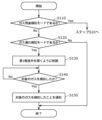
- FIG. 4 is a flowchart illustrating an example of the operation of the control device according to Embodiment 1.
- FIG. 5 is a flowchart showing another example of the operation of the control device according to Embodiment 1.
- FIG. FIG. 6 is a diagram schematically showing the configuration of a gas detection system according to Embodiment 2.
- FIG. 7A is a diagram for explaining gas concentration detection when there is a sufficient remaining amount of gas in the gas tank according to the second embodiment.
- FIG. 7B is a diagram for explaining gas concentration detection when the amount of gas remaining in the gas tank is small according to the second embodiment.
- FIG. 8 is a flow chart showing the operation of the control device according to the second embodiment.
- FIG. 9 is a first diagram showing an application example of the gas detection system according to the present disclosure.
- FIG. 10 is a second diagram showing an application example of the gas detection system according to the present disclosure.
- Patent Document 1 discloses a technique for calculating the remaining amount of gas such as gaseous fuel using a pressure sensor (pressure gauge).
- the pressure sensor may not be able to perform accurate detection (measurement) when the remaining amount of gas falls below a certain value. In other words, the reliability of the remaining amount of gas detected by the conventional technology is low.
- the inventors of the present application conducted extensive research on a gas detection system and a gas detection method that can detect the remaining amount of gas more accurately than before, and created the following gas detection system and gas detection method.
- each figure is a schematic diagram and is not necessarily strictly illustrated. Therefore, for example, scales and the like do not necessarily match in each drawing. Moreover, in each figure, the same code
- upper and lower does not refer to the upward direction (vertically upward) and the downward direction (vertical downward) in absolute spatial recognition, but is defined by the movement direction of the on-off valve in the switch. used as a term
- FIG. 1 A gas detection system according to the present embodiment will be described below with reference to FIGS. 1 to 5.
- FIG. 1 A gas detection system according to the present embodiment will be described below with reference to FIGS. 1 to 5.
- FIG. 1 is a partial cross-sectional view schematically showing the configuration of a gas detection system 1 according to this embodiment.
- FIG. 1 shows a schematic cross-sectional view of the pressure detector 10 in a state in which the hydrogen path (flow path) from the gas tank 110 to the gas detector 20 is blocked. Note that FIG. 1 shows the housings 11 and 21, the pressure detection valve 13, and the lid portion 14 in a cross-sectional view.
- the gas detection system 1 includes a pressure detector 10, a gas detector 20, a pressure reducing valve 30, a controller 40, a regulator 50, and a check valve 60.
- the gas detection system 1 is installed in a mobility (moving body) that uses hydrogen as fuel, such as a fuel cell vehicle (FCV), a fuel cell bicycle, a fuel cell drone, etc., and is a gas detection system for detecting the remaining amount of hydrogen in the mobility. System.
- FCV fuel cell vehicle
- FCV fuel cell vehicle
- FIG. 9 described later An example in which the gas detection system 1 is installed in a fuel cell vehicle (see FIG. 9 described later) will be described below.
- the fuel cell vehicle includes a gas tank 110 , a gas filling port 120 , a gas tank valve 130 , a pressure reducing valve 140 and a fuel cell (fuel cell stack) 150 in addition to the gas detection system 1 .
- the pressure detector 10 is an example of a switch, and has a pressure detection valve 13 that is connected between the gas tank 110 and the gas detector 20 and opens and closes the hydrogen path from the gas tank 110 to the gas detector 20 .
- the pressure detector 10 has a structure in which the pressure detection valve 13 opens and closes according to the pressure inside the gas tank 110 (internal pressure).
- the internal pressure is the pressure of hydrogen.
- the path in the present embodiment is formed by first pipe portion 161 , third pipe portion 163 , first internal space 10 a , communication hole 13 a , second internal space 10 b and pipe 170 .
- the pressure sensor 10 has a housing 11 , a partition membrane 12 , a pressure detection valve 13 , a lid portion 14 , a rod 15 and a spring 16 .
- the housing 11 is a box that accommodates the partition membrane 12, the pressure detection valve 13, the lid 14, the rod 15, and the spring 16 inside.
- the housing 11 is hermetically sealed with a third piping portion 163 forming a hydrogen path from the gas tank 110 and a piping 170 connecting the pressure detector 10 and the gas detector 20 connected. there is The housing 11 applies hydrogen pressure to the partition membrane 12 . Acting means that the partition membrane 12 is deformed (for example, elastically deformed) by the pressure of hydrogen.
- the expression that the configuration A and the configuration B are connected means that the configuration A and the configuration B are connected via a pipe (for example, a pipe or tube), and the configuration A and the configuration B It means that hydrogen can move between and through the piping.
- a fixed portion 11a to which one end of the partition membrane 12 is fixed is formed in the housing 11 .
- the fixed portion 11a is formed, for example, in a circumferential shape.
- the fixed portion 11a is, for example, a convex portion projecting from the inner surface of the housing 11 toward the center of the internal space of the housing 11, but is not limited thereto.
- the housing 11 is made of a material that can withstand the pressure of hydrogen.
- the housing 11 is made of metal, for example, but is not limited to this.
- the partition membrane 12 is a diaphragm whose periphery is fixed to the fixing portion 11a and which deforms (for example, elastically deforms) according to the action of hydrogen pressure.
- the partition membrane 12 is arranged so as to block the route between the third pipe portion 163 and the pipe 170 in the hydrogen route from the gas tank 110 to the gas detector 20, and has an opening 12a in which the pressure detection valve 13 is provided. It is a frame-shaped membrane.
- the partition membrane 12 separates the first internal space 10a and the second internal space 10b inside the housing 11 in a state in which the communication hole 13a is closed by the cover portion 14 as shown in FIG.
- the partition film 12 is provided so as to cover the space between the fixed portion 11a and the pressure detection valve 13 when viewed from the top and bottom direction.
- the vertical direction is, for example, a direction parallel to the direction in which the pressure detection valve 13 moves due to deformation of the partition membrane 12, and in the example of FIG. Moreover, in the present embodiment, the vertical direction is also a direction parallel to the direction in which the rod 15 extends.
- the partition membrane 12 is a circular thin plate such as stainless steel that bends when pressure is applied from one side.
- the pressure of hydrogen causes the partition membrane 12 to elastically deform, thereby moving the position of the pressure detection valve 13 in the vertical direction. For example, when the pressure of hydrogen decreases, the pressure detection valve 13 moves downward (in the direction opposite to the lid portion 14), and when the pressure of hydrogen increases, the pressure detection valve 13 moves upward (in the direction opposite to the lid portion 14). direction).
- the partition membrane 12 may be made of any material other than stainless steel as long as it is a plate-shaped member that can withstand the pressure of hydrogen and is bent by the pressure of hydrogen.
- the first internal space 10a is an internal space of the housing 11 separated by the partition membrane 12 and the pressure detection valve 13, and is connected to the gas tank 110 via the pipe 160 (third pipe portion 163). space, and in the example of FIG. 1, it is the internal space located below the second internal space 10b. Hydrogen in the gas tank 110 flows through the pipe 160 into the first internal space 10a. That is, the pressure of hydrogen in the first internal space 10a and the pressure of hydrogen in the gas tank 110 are the same. Also, the volume of the first internal space 10a corresponds to the pressure of hydrogen. When the hydrogen is consumed and the remaining amount of hydrogen in the gas tank 110 decreases and the pressure of hydrogen in the gas tank 110 decreases, the pressure of hydrogen in the first internal space 10a also decreases.
- the second internal space 10b is the internal space of the housing 11 separated by the partition membrane 12 and the pressure detection valve 13 and connected to the gas detector 20 via the pipe 170. In the example, it is an internal space located above the first internal space 10a.
- the pressure detection valve 13 is an example of an on-off valve, is fixed to the other end of the partition membrane 12 , and moves vertically due to elastic deformation of the partition membrane 12 .
- a communication hole 13a is formed through the pressure detection valve 13 in the vertical direction.
- the communication hole 13a is a through hole for communicating the first internal space 10a and the second internal space 10b in the housing 11, and communicates the first internal space 10a with the second internal space 10b in a state where the cover portion 14 is not closed. 2 communicates with the internal space 10b.
- the communication hole 13a forms a path for hydrogen flowing from the first internal space 10a to the second internal space 10b without being blocked by the lid portion 14 .
- the pressure detection valve 13 is made of a material that does not deform due to hydrogen pressure or the like.
- the pressure detection valve 13 is made of metal or resin, but is not limited to this.
- the lid portion 14 is a valve body provided to close the hydrogen path to the gas detector 20, and closes the hydrogen path between the gas tank 110 and the gas detector 20 by closing the communication hole 13a (blocking valve). do).
- the lid portion 14 is arranged in the second internal space 10b and closes the communication hole 13a from the gas tank 110 and the gas detector 20 side from the gas detector 20 side.
- the lid portion 14 is not particularly limited in size, shape, and material as long as it can close the hydrogen path by blocking the communication hole 13a.
- the position of the lid portion 14 is fixed by an adjusting device 50 . In other words, the lid portion 14 maintains a fixed position regardless of the hydrogen pressure in the gas tank 110 .
- the lid portion 14 is fixed to the end portion of the rod 15 on the pressure detection valve 13 side.
- the lid portion 14 and the rod body 15 may be integrally formed, for example.
- the rod 15 is connected to the lid portion 14 and the adjusting device 50 and is vertically movable in order to adjust the position of the lid portion 14 .
- the length of the rod 15 is determined in advance according to the remaining amount of hydrogen to be detected.
- the rod 15 is made of, for example, metal, resin, or the like, but the material is not particularly limited.
- the spring 16 is a compression spring formed in a helical shape, and the rod 15 is inserted inside.
- the gas detector 20 has a detection element 22 that detects hydrogen, and detects the presence or absence of hydrogen in this embodiment.
- the gas detector 20 detects whether the gas from the pressure detector 10 contains hydrogen.
- the gas detector 20 detects hydrogen leaking from the pressure detector 10 due to a gap between the pressure detection valve 13 and the lid portion 14 due to a decrease in hydrogen pressure.
- the gas detector 20 has a housing 21 , a detection element 22 , a first release valve 23 and a second release valve 24 .
- the housing 21 is a box that is connected to the pressure detector 10 via a pipe 170 and houses the detection element 22 inside.
- the housing 21 is sealed with the pipes 170 and 180 connected and the first release valve 23 and the second release valve 24 closed.
- the housing 21 is made of a material that can withstand the pressure of hydrogen.
- the housing 21 is made of metal, for example, but is not limited to this.
- the detection element 22 is an example of a gas sensor, and detects hydrogen (an example of a predetermined gas) within the internal space 20a.
- the sensing element 22 senses hydrogen.
- a semiconductor sensing element is exemplified.
- a semiconductor-type sensing element senses the presence of hydrogen by a change in conductivity of the semiconductor element, and is exemplified by the hydrogen sensor disclosed in Japanese Patent Application No. 2020-73461. Note that the sensing element 22 is not limited to a semiconductor sensing element, and any existing element may be used.
- the first release valve 23 and the second release valve 24 are one or more release valves for releasing hydrogen from the pressure detector 10 to the outside of the gas detector 20.
- the first release valve 23 and the second release valve 24 are opened and closed under the control of the controller 40 .
- the first release valve 23 is a release valve for opening and closing the path between the internal space 20a and the external space.
- the first release valve 23 is normally closed, and may be opened under the control of the control device 40 when the detection element 22 detects hydrogen.
- the second release valve 24 is a release valve for opening and closing the path between the internal space 20 a and the pipe 180 connecting the gas detector 20 and the fuel cell 150 .
- the second release valve 24 is normally closed, and may be opened under the control of the control device 40 when the detection element 22 detects hydrogen.
- the pressure reducing valve 30 is arranged in a path (for example, on the pipe 170) between the pressure detector 10 and the gas detector 20, and the pressure sensor 10 to the gas detector 20 (that is, the gas tank 110 to the gas detector 20). It is a regulator that adjusts the pressure of hydrogen flowing into the The pressure (internal pressure) of hydrogen in the gas tank 110 is high, and may exceed 80 Mpa, for example. If such high-pressure hydrogen flows into the internal space 20a without being decompressed, the pressure may destroy the sensing element 22 in some cases.
- the hydrogen is decompressed via the decompression valve 30 before flowing into the gas detector 20 .
- the pressure reducing valve 30 may reduce the hydrogen pressure to such an extent that the sensing element 22 is not destroyed.
- the pressure reducing valve 30 may reduce the pressure of hydrogen to about atmospheric pressure (0.1 Mpa), for example. Further, the pressure reducing valve 30 may reduce the pressure of hydrogen to approximately the same pressure as the pressure of hydrogen reduced by the pressure reducing valve 140 . If the sensing element 22 has a structure that does not break even if the inflowing hydrogen is of high pressure, the pressure reducing valve 30 may not be provided.
- FIG. 2 is a block diagram showing the functional configuration of control device 40 according to the present embodiment.
- the control device 40 has a control section 41 and a communication section 42 . That is, the control device 40 has a communication function (for example, wireless communication function).
- a communication function for example, wireless communication function
- the control unit 41 controls each component based on the hydrogen detection result of the detection element 22, for example.
- the control unit 41 controls the position of the lid unit 14 by, for example, outputting a gas detection signal indicating that the detection element 22 has detected hydrogen to the adjusting device 50 . Further, the control unit 41 controls to open at least one of the first release valve 23 and the second release valve 24 when the detection element 22 detects hydrogen. After the detection element 22 detects hydrogen and the adjustment device 50 moves the cover portion 14 according to the gas detection signal to close the communication hole 13a, the control portion 41 opens the first release valve 23 and the second release valve. 24 is controlled to open. For example, when the detection element 22 detects hydrogen, the control unit 41 should open at least the second release valve 24 .
- the communication unit 42 is an example of a wireless communication unit, and is a communication circuit (communication module) for communicating (wireless communication) with an external device of the fuel cell vehicle on which the gas detection system 1 is mounted.
- the communication unit 42 detects hydrogen in the mobile terminal (for example, a smartphone) of the user riding in the fuel cell vehicle or in the monitor remotely monitoring the fuel cell vehicle. You may send information indicating that.
- Wireless communication is performed by, for example, radio wave communication, but the method of wireless communication is not limited to this, and any communication method may be used.
- the communication unit 42 may be a communication unit different from the communication unit pre-installed in the fuel cell vehicle.
- the communication unit 42 may be a dedicated communication unit for the gas detection system 1, or may be included in a communication unit pre-mounted in the fuel cell vehicle. Note that inclusion means that the communication unit pre-installed in the fuel cell vehicle has the function of the communication unit 42 .
- the adjustment device 50 is an example of an adjustment unit, and based on a gas detection signal (a hydrogen detection signal in the present embodiment) from the control device 40, the lid is adjusted to block the communication hole 13a. Adjust the position of the part 14 .
- the adjusting device 50 is connected to the rod 15 and adjusts the position of the lid 14 by moving the rod 15 vertically, for example.
- the adjustment device 50 may have a configuration for vertically moving the rod 15 by a motor or the like, or may have a configuration for vertically moving the rod 15 by an electromagnetic force. good.
- the adjustment device 50 may include, for example, a coil, a yoke, a fixed core, etc., and the rod 15 may function as a movable core.
- the adjusting device 50 adjusts the position of the lid portion 14 step by step.
- the adjustment device 50 may move the rod 15 downward by a predetermined distance each time the gas detection signal is acquired.
- the check valve 60 is arranged between the gas detector 20 and the fuel cell 150 and is a check valve for preventing backflow of hydrogen from the fuel cell 150 to the gas detector 20 .
- Check valve 60 is provided on piping 180 that connects gas detector 20 and fuel cell 150 .
- the gas detection system 1 does not calculate the remaining amount of hydrogen from the pressure of hydrogen, but directly detects hydrogen using the detection element 22 that detects hydrogen, and uses the detection result to calculate the remaining amount of hydrogen. has a configuration that can calculate
- the gas detection system 1 may be battery operated.
- the gas detection system 1 may, for example, incorporate a battery (not shown), or may operate by being supplied with power from a battery mounted on a fuel cell vehicle.
- a dedicated power supply for operating the gas detection system 1 may be mounted on the fuel cell vehicle.
- the gas tank 110 is a fuel tank that stores pressurized fuel as a predetermined gas, which is fuel for the fuel cell vehicle in which the gas tank 110 is mounted.
- gas tank 110 is a hydrogen tank that stores hydrogen (hydrogen gas).
- Gas tank 110 is configured to be able to store hydrogen at a pressure of about 80 MPa, for example.
- the gas tank 110 is made of metal, for example, but is not limited to this.
- the predetermined gas is not limited to hydrogen, and gaseous fuels (for example, compressed gaseous fuels) such as natural gas and liquefied petroleum gas used as fuel for mobility, combustible gases other than hydrogen, etc. can be stored. good too.
- gaseous fuels for example, compressed gaseous fuels
- the gas detection system 1 may be a system that detects the remaining amount of gas other than hydrogen.
- the gaseous fuel is fuel that is gaseous at normal temperature and normal pressure.
- the gas tank 110 is connected to each of the gas detection system 1 (specifically, the pressure detector 10) and the fuel cell 150 via the gas tank valve 130.
- the gas filling port 120 is a filling port for filling the gas tank 110 with gas (hydrogen in this embodiment) from an external hydrogen supply facility (not shown). Hydrogen is supplied by inserting a dedicated device (for example, a filling plug) into the gas filling port 120 . When hydrogen is filled from the gas filling port 120 , the hydrogen is filled into the gas tank 110 via the gas tank valve 130 .
- the gas tank valve 130 is a valve that controls the inflow and outflow of gas (hydrogen in this embodiment) in the gas tank 110 .
- the gas tank valve 130 is connected with the gas tank 110 and the gas detection system 1 . Also, the gas tank valve 130 is connected to the fuel cell 150 via a pipe 160 (second pipe portion 162).
- the gas tank valve 130 has a check valve 131.
- the check valve 131 is arranged between the gas filling port 120 and the piping 160 branched in three directions, and prevents the backflow of hydrogen from the gas detection system 1, the gas tank 110 and the fuel cell 150 to the gas filling port 120. It is a check valve for
- the pressure reducing valve 140 is a regulator that is arranged on the path between the gas tank 110 and the fuel cell 150 (for example, on the second pipe section 162) and adjusts the pressure of hydrogen flowing from the gas tank 110 to the fuel cell 150.
- the pressure reducing valve 140 may, for example, reduce the pressure of hydrogen to approximately atmospheric pressure.
- a pressure regulating valve may be arranged between the pressure reducing valve 140 and the fuel cell 150 to further regulate the pressure.
- the fuel cell 150 uses a chemical reaction between the hydrogen filled in the gas tank 110 and oxygen in the air to generate electricity.
- the electricity generated by the fuel cell 150 is used to drive the driving motor, thereby driving the fuel cell vehicle.
- FIG. 1 omits illustration of an air supply unit that supplies air to the fuel cell 150, an exhaust unit that exhausts gas discharged from the fuel cell, and the like.
- a pipe 160 is a pipe that connects the gas tank 110 and the fuel cell 150 and the gas tank 110 and the pressure detector 10 .
- the pipe 160 includes a first pipe portion 161 from the branch point P to the gas tank 110, a second pipe portion 162 from the branch point P to the fuel cell 150, and a third pipe portion 163 from the branch point P to the pressure detector 10. and Hydrogen is supplied from the gas tank 110 to the fuel cell 150 via the first piping section 161 and the second piping section 162 . Hydrogen flows from the gas tank 110 into the pressure detector 10 via the first pipe portion 161 and the third pipe portion 163 .
- a pipe 170 is a pipe that connects the pressure detector 10 and the gas detector 20 .
- a pipe 180 is a pipe that connects the gas detector 20 and the fuel cell 150 .
- the pipes 160, 170 and 180 are composed of pipes or tubes.
- FIG. 3 is a diagram schematically showing the operation of the gas detection system 1 according to this embodiment. Arrows shown in FIG. 3 indicate inflow routes of hydrogen. The thickness of the arrow indicates the pressure of hydrogen, and the thicker the arrow, the higher the pressure of hydrogen. In addition, in FIG. 3, only the components for explaining the operation of the gas detection system 1 are illustrated, and the illustration of some components (such as the pressure reducing valve 30) is omitted.
- FIG. 3 shows the state of the gas detection system 1 when the remaining amount of hydrogen in the gas tank 110 is sufficient and the internal pressure of the gas tank 110 is high.
- the pressure of hydrogen causes the partition membrane 12 to elastically deform, which pushes the pressure detection valve 13 upward toward the lid portion 14 , and the pressure detection valve 13 contacts the lid portion 14 .
- the communication hole 13a of the pressure detection valve 13 is closed by the cover portion 14, so that the hydrogen in the first internal space 10a cannot flow into the second internal space 10b.
- FIG. 3(a) shows a state in which the pressure detection valve 13 is closed.
- FIG. 3 shows the state of the gas detection system 1 when the remaining amount of hydrogen in the gas tank 110 decreases from the state of (a) of FIG. 3 and the internal pressure of the gas tank 110 becomes equal to or lower than the first pressure. .
- the amount of elastic deformation of the partition membrane 12 is reduced (for example, the partition membrane 12 is loosened) due to the decrease in the pressure of hydrogen, so that the pressure detection valve 13 is pushed down to the opposite side (lower side) of the lid portion 14 .
- the pressure detection valve 13 is separated from the lid portion 14 .
- the communication hole 13a of the pressure detection valve 13 is no longer blocked by the lid portion 14, so that the hydrogen in the first internal space 10a can flow into the second internal space 10b.
- the pressure detection valve 13 is open. It can also be said that the pressure detection valve 13 is a valve that opens when the pressure of hydrogen becomes equal to or lower than the first pressure.
- the pressure detection valve 13 automatically transitions from the closed state to the open state as the pressure of hydrogen decreases. It can also be said that the pressure detection valve 13 transitions from the closed state to the open state using the remaining amount of hydrogen in the gas tank 110 (that is, the pressure of hydrogen).
- the automatic transition from the closed state to the open state means that the pressure detection valve 13 opens naturally without applying any force other than the pressure of hydrogen.
- the first pressure is set in advance and stored in a storage unit (not shown) of the gas detection system 1.
- the first pressure is a pressure corresponding to the remaining amount of hydrogen to be detected in the gas detection system 1 .
- the state of (a) in FIG. is the pressure corresponding to 1/2 of the remaining amount.
- Such pressure can be obtained in advance by experiments or the like.
- FIG. 3(c) is a diagram showing how the pressure detection valve 13 is closed after hydrogen is detected in the state of FIG. 3(b).
- the control device 40 outputs a gas detection signal indicating that hydrogen has been detected to the adjustment device 50 .
- the adjustment device 50 adjusts the position of the lid portion 14 so as to close the pressure detection valve 13 .
- the adjusting device 50 moves the lid portion 14 toward the pressure detection valve 13 (downward) in order to close the communication hole 13a. For example, when the pressure becomes equal to or lower than the second pressure corresponding to the remaining amount of 1/4 of the full filling, the cover portion 14 is moved toward the pressure detection valve 13 to the position where the pressure detection valve 13 opens.
- the adjustment device 50 moves the rod 15 toward the pressure detection valve 13 so as to move the lid portion 14 toward the pressure detection valve 13 by a predetermined distance.
- the predetermined distance is set in advance according to the pressure corresponding to the remaining amount of hydrogen to be detected in the gas detection system 1 .
- the pressure detection valve 13 opens due to a drop in the pressure of hydrogen, but the adjustment device 50 controls the position of the lid portion 14 so that the pressure detection valve 13 is closed again.
- FIG. 3 is a state in which the pressure detection valve 13 is closed in (c) of FIG. It is a figure which shows a mode to carry out (discharge).
- the control device 40 opens at least one of the first release valve 23 and the second release valve 24 to release the hydrogen in the gas detector 20.
- (d) of FIG. 3 shows an example in which the control device 40 opens both the first release valve 23 and the second release valve 24 .
- the hydrogen used for hydrogen detection can be sent to the fuel cell 150 .
- the pressure on the fuel cell 150 side is lower than the pressure on the internal space 20a.
- the first release valve 23 may be opened further. Thereby, the hydrogen in the internal space 20a can be effectively sent to the fuel cell 150.
- the control device 40 preferably opens at least one of the first release valve 23 and the second release valve 24 while the pressure detection valve 13 is closed. Whether or not the pressure detection valve 13 is closed may be determined, for example, by the adjustment device 50 detecting a change in the pressure applied to the lid portion 14 when the lid portion 14 contacts the pressure detection valve 13 . Further, whether or not the pressure detection valve 13 is closed is determined, for example, by the fact that hydrogen is no longer detected by the detection element 22 after a predetermined time has elapsed since at least one of the first release valve 23 and the second release valve 24 was opened. may be determined by
- FIG. 3 shows the gas detection system when the remaining amount of hydrogen in the gas tank 110 has decreased from the state of (d) in FIG. 1 is shown.
- the pressure detection valve 13 pushes up the lid portion 14, and the pressure detection valve 13 and the lid portion 14 are in contact with each other.
- FIG. 3(e) shows a state in which the pressure detection valve 13 is closed.
- FIG. 3(f) shows the state of the gas detection system 1 when the remaining amount of hydrogen in the gas tank 110 further decreases from the state of FIG. 3(e) and the internal pressure of the gas tank 110 becomes equal to or lower than the second pressure. show.
- the amount of elastic deformation of the partition membrane 12 decreases due to the decrease in the pressure of hydrogen, so that the pressure detection valve 13 is pushed down to the opposite side (lower side) of the lid portion 14 , and the pressure detection valve 13 is pushed downward to the lid portion 14 . away from As a result, the communication hole 13a of the pressure detection valve 13 is no longer blocked by the lid portion 14, so that the hydrogen in the first internal space 10a can flow into the second internal space 10b.
- FIG. 3(f) shows a state in which the pressure detection valve 13 is open. It can also be said that the pressure detection valve 13 is a valve that opens when the pressure of hydrogen becomes equal to or lower than the second pressure.
- the gas detection system 1 repeats the cycle of closing the pressure detection valve 13, opening the pressure detection valve 13 due to a decrease in the pressure of hydrogen in the gas tank 110, and closing the pressure detection valve 13 by the adjusting device 50. By doing so, it is possible to detect a desired remaining amount of gas (for example, a plurality of discrete amounts of remaining gas).
- the cycle shown in FIG. 3 is not limited to being repeated, and the pressure detection valve 13 may be changed from the closed state to the open state only once. That is, the gas detection system 1 may have a configuration in which the adjustment device 50 is not provided and the lid portion 14 is fixed at a predetermined position without moving.
- FIG. 4 is a flow chart showing the operation (gas detection method) of the control device 40 according to the present embodiment. Steps that are not operations of the control device 40 are indicated by dashed frames.
- the control section 41 of the control device 40 controls the lid section 14 to the initial position (S10).
- the control unit 41 outputs a control signal for moving the lid portion 14 to the initial position to the adjusting device 50 to move the lid portion 14 to the initial position.
- the pressure detection valve 13 is closed.
- the pressure detection valve 13 is, for example, in the state shown in FIG. 3(a). Note that the detection element 22 may start detecting the presence or absence of hydrogen with the movement of the lid portion 14 to the initial position as a trigger.
- the pressure detection valve 13 opens (the pressure detection valve 13 opens) due to the decrease in the remaining amount of hydrogen (lowering gas pressure) (S20).
- the pressure detection valve 13 transitions from the closed state to the open state.
- the control unit 41 determines whether or not the detection element 22 has detected hydrogen (S30).
- the control unit 41 makes determination in step S30 based on the detection result of the detection element 22 .
- the control unit 41 outputs a gas detection signal to the adjustment device 50 (S40).
- the control unit 41 closes the pressure detection valve 13, that is, changes the pressure detection valve 13 from the open state to the closed state.
- the detection element 22 does not detect hydrogen (No in S30)
- the control unit 41 returns to step S30 and continues the determination in step S30 until hydrogen is detected.
- the controller 41 does not move the lid 14 unless, for example, hydrogen is detected.
- the case where the detection element 22 does not detect hydrogen is, for example, the case where the remaining amount of hydrogen is less than or equal to a predetermined amount.
- control unit 41 calculates the remaining amount of hydrogen based on the detection result of the detection element 22 (S50).
- the control unit 41 calculates the remaining amount of hydrogen based on the position of the lid 14 when the detection element 22 detects hydrogen.
- the control unit 41 may calculate the remaining amount of hydrogen, for example, based on a table that associates the position of the lid 14 with the remaining amount of hydrogen.
- the remaining amount of hydrogen is an example of the remaining amount of gas.
- the control unit 41 notifies the calculated remaining amount of hydrogen (S60).
- the control unit 41 notifies the mobile terminal of the user of the remaining amount of hydrogen, for example, via the communication unit 42 .
- the detection of hydrogen by the detection element 22 (the detection element 22 reacts) is used as a trigger to notify the remaining amount of hydrogen, so that the control unit 41 can warn the user or the like that the remaining amount of hydrogen is low. be.
- the notification may include, for example, information prompting the user to fill up with hydrogen, or information indicating the distance that can be traveled with the remaining amount.
- the gas detection system 1 detects hydrogen in order to calculate the remaining amount of hydrogen in the gas tank 110 in the above description, it may be used for other purposes.
- the gas detection system 1 may be used, for example, as an anomaly detection system that detects gas leakage outside the gas detection system 1 .
- FIG. 5 is a flow chart showing another example of the operation of the control device 40 according to this embodiment.
- the control unit 41 determines whether or not the current mode is the remaining amount of gas detection mode (S110). For example, if the control unit 41 has received an instruction to operate in the remaining amount of gas detection mode via the communication unit 42, it determines Yes in step S110, and if the instruction has not been received, the step No may be determined in S110. Further, when the control unit 41 stores schedule information in which a time zone for operating in the remaining gas detection mode and a time zone for operating in the gas leakage detection mode are set, the schedule information and the current time are combined. Based on this, the determination in step S110 may be made.
- step S110 when the control unit 41 is in the remaining amount of gas detection mode (Yes in S110), the control unit 41 proceeds to step S10 shown in FIG. 4, and performs the processing after step S10. Further, if the control unit 41 is not in the remaining amount of gas detection mode (No in S110), it further determines whether the current mode is the gas leakage detection mode (S120). For example, if the control unit 41 has received an instruction to operate in the gas leakage detection mode via the communication unit 42, it determines Yes in step S120, and if the instruction has not been received, step S120. may be determined as No.
- control unit 41 stores schedule information in which a time zone for operating in the remaining gas detection mode and a time zone for operating in the gas leakage detection mode are set, the schedule information and the current time are combined. Based on this, the determination in step S120 may be made.
- step S120 if the gas leak detection mode is set (Yes in S120), the controller 41 proceeds to step S130, and if not in the gas leak detection mode (No in S120), the process ends.
- control unit 41 controls the first release valve 23 and the second release valve 24 so that only the first release valve 23 of the first release valve 23 and the second release valve 24 is opened (S130).
- the gas in the space flows into the gas detector 20 from the space outside the gas detection system 1 .
- control unit 41 determines whether or not the target gas has been detected in the gas that has flowed in from the external space (S140).
- the control unit 41 makes a determination in step S140 based on whether or not the detection element 22 has detected the target gas.
- the target gas is set in advance, and is hydrogen in this embodiment.
- the control unit 41 notifies that the target gas has been detected (gas leakage has occurred) (S150). For example, the control unit 41 notifies the mobile terminal of the user via the communication unit 42 that the target gas has been detected. Note that the notification may include information indicating, for example, the type of detected gas, the concentration of the detected gas, the time when the target gas was detected, and the like. If the control unit 41 has not detected the target gas (No in S140), the control unit 41 returns to step S140 to continue detecting the target gas. The control unit 41 may continue detection of the target gas for a predetermined period of time, for example.
- the control unit 41 has two operation modes, the remaining amount of gas detection mode and the gas leakage detection mode.
- the control mode may be switched by remote control from the outside.
- the control unit 41 opens the first release valve 23 to allow the gas in the external space to flow into the gas detector 20, and the flowed gas includes the target gas.
- the detection element is made to detect whether or not the Further, when performing control in the remaining gas amount detection mode, the control unit 41 opens at least the second release valve 24 to allow the hydrogen detected by the detection element 22 to flow into the fuel cell 150 .
- the gas detection system 1 is a gas detection system for detecting the remaining amount of hydrogen (an example of the remaining amount of gas) in the gas tank 110 storing hydrogen (an example of a predetermined gas).
- the gas detection system 1 directly detects hydrogen with the gas detector 20 without using a pressure sensor. is difficult to detect. In other words, since the gas detection system 1 directly detects hydrogen with the gas detector 20, it is possible to accurately detect the remaining amount of gas even when the remaining amount of gas is small. Therefore, it is possible to realize the gas detection system 1 that can detect the remaining amount of gas more accurately than before.
- the pressure detector 10 also has a pressure detection valve 13 that opens when the pressure of hydrogen falls below a predetermined pressure, and the gas detector 20 detects the presence or absence of hydrogen.
- the gas detection system 1 has a configuration in which the detection element 22 detects hydrogen when the pressure of hydrogen becomes equal to or lower than a predetermined pressure. In other words, the gas detection system 1 can detect a decrease in the remaining amount of gas in the gas tank 110 . Further, since there is a correlation between the pressure of hydrogen and the remaining amount of hydrogen, the remaining amount of hydrogen in the gas tank 110 can be detected when the detection element 22 detects hydrogen.
- the pressure detection valve 13 is formed with a communication hole 13a for communication between the gas tank 110 and the gas detector 20, and the gas detection system 1 further includes a lid portion 14 that closes the communication hole 13a.
- An adjustment device 50 (an example of an adjustment unit) for adjustment is provided. Then, when the gas detector 20 detects hydrogen, the adjustment device 50 moves the lid portion 14 toward the pressure detection valve 13 side to close the communication hole 13a.
- the gas detection system 1 can detect the remaining amount of gas in multiple stages according to the decrease in the remaining amount of gas in the gas tank 110 .
- the pressure sensor 10 further includes a partition membrane 12 having an opening 12a disposed so as to block the path of hydrogen and having a pressure detection valve 13 provided thereon, the partition membrane 12 and the pressure detection valve 13. It has a housing 11 that applies pressure to the partition membrane 12, and a lid portion 14 that closes the communication hole 13a from the gas tank 110 and the gas detector 20 side from the gas detector 20 side.
- a pressure reducing valve 30 is arranged in a portion of the path between the pressure detector 10 and the gas detector 20 to reduce the pressure of hydrogen flowing from the pressure detector 10 to the gas detector 20 .
- the gas detector 20 also includes one or more release valves (for example, at least one of the first release valve 23 and the second release valve 24) for releasing hydrogen from the pressure sensor 10 to the outside of the gas detector 20. and a control unit 41 for controlling opening and closing of one or more release valves.
- one or more release valves for example, at least one of the first release valve 23 and the second release valve 24 for releasing hydrogen from the pressure sensor 10 to the outside of the gas detector 20.
- a control unit 41 for controlling opening and closing of one or more release valves.
- the opening and closing of one or more release valves is controlled by the control unit 41, and the hydrogen in the gas detector 20 can be released to the outside of the gas detector 20. It is possible to effectively detect the remaining amount of hydrogen.
- the one or more release valves include a first release valve 23 that opens and closes the path between the internal space 20a of the gas detector 20 and the space outside the gas detector 20, and hydrogen is supplied from the gas detector 20 and the gas tank 110. and a second release valve 24 for opening and closing the path between the fuel cell 150 and the control unit 41, when releasing hydrogen to the outside of the gas detector 20, the first release valve 23 and the second release valve At least one of the valves 24 is opened.
- the hydrogen in the gas detector 20 can be released to at least one of the external space and the fuel cell 150.
- control unit 41 has a gas leakage detection mode for detecting gas leakage in the external space and a remaining gas detection mode for detecting the hydrogen remaining amount of hydrogen in the gas tank 110, and controls in the gas leakage detection mode.
- the first release valve 23 is opened to allow the gas in the external space to flow into the gas detector 20 and control is performed in the gas residual amount detection mode
- at least the second release valve 24 is opened to detect the gas concentration.
- the hydrogen is supplied to the fuel cell 150 .
- control unit 41 can detect gas leakage in addition to detecting the remaining amount of gas.
- the gas detection system 1 can effectively utilize the hydrogen used for detection.
- a check valve 60 is further provided between the gas detector 20 and the fuel cell 150 to prevent backflow of gas from the fuel cell 150 to the gas detector 20 .
- erroneous detection by the detection element 22 due to reverse flow of hydrogen from the fuel cell 150 to the gas detector 20 can be suppressed. Therefore, according to the check valve 60, hydrogen detection accuracy can be further improved.
- a communication unit 42 (an example of a wireless communication unit) that communicates with an external device of the fuel cell vehicle (an example of a moving object) on which the gas detection system 1 is mounted.
- the detection result of the gas detector 20 can be transmitted to an external device, so the remaining amount of gas in the mobile object can be remotely monitored.
- the gas detection system 1 is capable of battery operation.
- the gas detector 20 detects hydrogen as a predetermined gas.
- the remaining amount of hydrogen can be detected with high accuracy, so, for example, the reliability of detecting the remaining amount of hydrogen in mobile objects that use hydrogen as fuel is improved. Improving the reliability of detecting the remaining amount of hydrogen can contribute to the further spread of such vehicles.
- the gas detection method according to the present embodiment is a gas detection method for detecting the remaining amount of hydrogen (an example of the remaining amount of gas) in the gas tank 110 storing hydrogen (an example of a predetermined gas).
- 1 is a gas detection method in system 1;
- the gas detection system 1 includes a gas detector 20 that detects the presence or absence of hydrogen, and a pressure detection valve that is connected between the gas tank 110 and the gas detector 20 and opens and closes the path of hydrogen from the gas tank 110 to the gas detector 20. and a pressure sensor 10 having 13 .
- the pressure detection valve 13 is naturally opened (S20). 20 (S30).
- the gas detection method directly detects hydrogen with the gas detector 20 without using a pressure sensor. can be calculated. Moreover, since the gas detection method utilizes a drop in hydrogen pressure to open the pressure detection valve 13, it is possible to detect a decrease in the amount of hydrogen remaining in the gas tank 110. FIG. Therefore, it is possible to realize a gas detection method capable of detecting the remaining amount of gas more accurately than the conventional method.
- Embodiment 2 A gas detection system according to the present embodiment will be described below with reference to FIGS. 6 to 8.
- FIG. it demonstrates centering on difference with Embodiment 1, and abbreviate
- FIG. 6 is a partial cross-sectional view schematically showing the configuration of the gas detection system 1a according to this embodiment.
- FIG. 6 shows a schematic cross-sectional view of the gas extractor 210 in the middle of opening and closing the hydrogen path (channel).
- the lid 14, the housings 21 and 211, and the gas sampling valve 213 are shown in cross section.
- the gas detection system 1a according to the present embodiment is different from the gas detection system 1 according to Embodiment 1 in that it includes a gas sampler 210 instead of the pressure detector 10 .
- the gas detection system 1a has a configuration for sequentially detecting the remaining amount of gas (for example, at preset timings).
- the gas detection system 1a samples the hydrogen in order to detect the concentration of the hydrogen.
- the gas detection system 1a includes a gas extractor 210, a gas detector 20, a pressure reducing valve 30, a control device 40, an adjustment device 50, and a check valve 60.
- the gas extractor 210 is an example of a switch, which opens and closes the path at predetermined time intervals under the control of the adjustment device 50, and releases an amount of hydrogen corresponding to the remaining amount of hydrogen in the gas tank 110 at predetermined time intervals. flow into the detector 20;
- the gas extractor 210 has a housing 211 , a gas sampling valve 213 , a lid portion 14 , a rod 15 and a spring 16 .
- the path in the present embodiment is formed by first pipe portion 161 , third pipe portion 163 , first internal space 210 a , communication hole 211 c , second internal space 210 b and pipe 170 .
- the housing 211 is a box that houses the gas sampling valve 213, the lid 14, the rod 15, and the spring 16 inside.
- the housing 211 is hermetically sealed with a third piping portion 163 forming a hydrogen path from the gas tank 110 and a piping 170 connecting the gas extractor 210 and the gas detector 20 connected.
- An engaging portion 211 a that engages with the gas sampling valve 213 is formed on the housing 211 .
- the first internal space 210a and the second internal space 210b are blocked by the engagement between the gas sampling valve 213 and the engaging portion 211a. That is, the gas sampling valve 213 is engaged with the engaging portion 211a to close the hydrogen path (flow path) between the gas tank 110 and the gas detector 20 .
- the engaging portion 211a has an inclined surface 211b that is inclined so that the distance decreases toward the lid portion 14.
- a communication hole 211c is formed through the engaging portion 211a in the vertical direction.
- the communication hole 211c is formed so that the diameter becomes smaller toward the lid portion 14 .
- the communication hole 211c is a truncated cone-shaped through hole that communicates the first internal space 210a and the second internal space 210b.
- the gas sampling valve 213 is an example of an on-off valve, and is arranged to pass through the communication hole 211c.
- the gas sampling valve 213 has a shape corresponding to the inclined surface 211b of the engaging portion 211a.
- the gas sampling valve 213 has a tapered shape that tapers toward the lid portion 14 .
- the gas sampling valve 213 is fixed to the lid portion 14, and moves up and down together with the lid portion 14 at predetermined time intervals under the control of the adjusting device 50 to open and close the path.
- the position of the gas sampling valve 213 when closing the path is an example of the first position.
- the first position is the position of the gas sampling valve 213 where the inclined surface 211b and the gas sampling valve 213 abut and there is no gap between the inclined surface 211b and the gas sampling valve 213 .
- the position of the gas sampling valve 213 when the second position opens the path is an example of the second position.
- the inclined surface 211b and the gas sampling valve 213 are not in contact with each other, and a predetermined gap 210c (see, for example, FIGS. 7A and 7B) is formed between the inclined surface 211b and the gas sampling valve 213. This is the position where the
- the housing 211 is made of a material that can withstand the pressure of hydrogen.
- the housing 211 is made of metal, for example, but is not limited to this.
- the sensing element 22 is configured to be capable of sensing the concentration of hydrogen.
- the adjustment device 50 opens and closes the gas sampling valve 213 at predetermined time intervals to extract hydrogen for hydrogen concentration detection from the first internal space 210a to the second internal space 210b.
- the regulator 50 momentarily opens the gas sampling valve 213, for example, at predetermined time intervals. Instantaneous is set in advance, for example, about 0.1 seconds, but is not limited to this.
- the predetermined time interval is constant regardless of, for example, the remaining amount of hydrogen (hydrogen pressure).
- the predetermined time interval is constant regardless of the elapsed time from the start of detection of the concentration of hydrogen, for example.
- the adjustment device 50 may electromagnetically move the gas sampling valve 213 when opening the gas sampling valve 213 .
- the adjustment device 50 has a coil, a yoke, a fixed iron core, etc., and the rod 15 is made of a magnetic material.
- Gas sampling valve 213 may be moved such that valve 213 is in an open state.
- the regulating device 50, the rod 15 and the gas sampling valve 213 may be so-called solenoid valves.
- closing the gas sampling valve 213 may be performed by, for example, the elastic force of the spring 16 in addition to the hydrogen pressure.
- the adjusting device 50 and the spring 16 are an example of a moving part (moving mechanism) that moves the gas sampling valve 213 between a first position that closes the gas sampling valve 213 and a second position that opens the gas sampling valve 213. be.
- a method for opening and closing the gas sampling valve 213 is not particularly limited.
- the spring 16 acts to assist the operation of the gas sampling valve 213 to close the path by the pressure of hydrogen.
- FIG. 7A is a diagram for explaining detection of gas concentration when there is a sufficient remaining amount of gas in gas tank 110 according to the present embodiment.
- FIG. 7B is a diagram for explaining detection of gas concentration when the amount of gas remaining in the gas tank is small according to the present embodiment.
- Arrows shown in FIGS. 7A and 7B indicate inflow routes of hydrogen. The thickness of the arrow indicates the amount of inflow of hydrogen, and the thicker the arrow, the greater the amount of inflow of hydrogen. A large inflow of hydrogen corresponds to a high pressure of hydrogen.
- FIGS. 7A and 7B show only the components for explaining the operation of the gas detection system 1a, and omit the illustration of some components (such as the pressure reducing valve 30).
- FIG. 7A shows how the gas detection system 1a is sampling hydrogen (the gas sampling valve 213 is open) when the gas tank 110 has a sufficient amount of hydrogen remaining and the internal pressure of the gas tank 110 is high. .
- the pressure of hydrogen since the pressure of hydrogen is high, the amount of hydrogen flowing into the gas detector 20 from the first internal space 210a through the gap 210c between the inclined surface 211b and the gas sampling valve 213 is large. As a result, the hydrogen concentration in the gas detector 20 becomes high, so that the detection result of the hydrogen concentration of the sensing element 22 becomes a high value.
- FIG. 7B shows how the gas detection system 1a is sampling hydrogen (the gas sampling valve 213 is open) when the amount of hydrogen remaining in the gas tank 110 is small and the internal pressure of the gas tank 110 is low. .
- the hydrogen pressure is low, the amount of hydrogen flowing into the gas detector 20 from the first internal space 210a through the gap 210c between the inclined surface 211b and the gas sampling valve 213 is small.
- the hydrogen concentration in the gas detector 20 becomes low, so the detection result of the hydrogen concentration of the sensing element 22 becomes a low value.
- the hydrogen concentration is detected by utilizing the fact that the amount of hydrogen flowing into the gas detector 20 varies depending on the internal pressure (hydrogen pressure) of the gas tank 110 .
- the position of the gas sampling valve 213, the opening time of the gas sampling valve 213, and the size of the gap 210c between the gas sampling valve 213 and the inclined surface 211b are the same.
- the second position of the gas sampling valve 213 shown in FIG. 7A and the second position of the gas sampling valve 213 shown in FIG. 7B are the same position. That is, the second position is the same regardless of the remaining amount of hydrogen (hydrogen pressure).
- FIG. 8 is a flowchart showing the operation (gas detection method) of control device 40 according to the present embodiment.
- control unit 41 of the control device 40 opens and closes the gas sampling valve 213 at predetermined time intervals (S210). For example, the control unit 41 moves the gas sampling valve 213 vertically at predetermined time intervals using the adjusting device 50 .
- the detection element 22 detects the concentration of hydrogen (hydrogen concentration) that has flowed into the gas detector 20 (S220). After the detection element 22 detects the hydrogen concentration, the control unit 41 may open at least the second release valve 24 to send hydrogen to the fuel cell 150 .
- control unit 41 calculates the remaining amount of hydrogen (hydrogen remaining amount) in the gas tank 110 based on the hydrogen concentration detected by the detection element 22 (S230). For example, the control unit 41 may calculate the current remaining amount of hydrogen based on the hydrogen concentration detected by the detection element 22 and a table showing the relationship between the hydrogen concentration and the remaining amount of hydrogen.
- control unit 41 notifies the calculated remaining amount of hydrogen (S240).
- the control unit 41 notifies the mobile terminal of the user of the remaining amount of hydrogen, for example, via the communication unit 42 .
- the notification may include, for example, information prompting the user to fill up with hydrogen, or information indicating the distance that can be traveled with the remaining amount.
- the gas sampling device 210 (an example of a switch) of the gas detection system 1a according to the present embodiment has the gas sampling valve 213 (an example of an on-off valve) that opens and closes the path at predetermined time intervals. Then, the gas detector 20 detects the concentration of hydrogen (an example of a predetermined gas).
- the gas detection system 1a directly detects the hydrogen concentration with the gas detector 20 without using a pressure sensor, it is difficult for the detection accuracy to change depending on the remaining amount of hydrogen as in the case of using a pressure sensor. .
- the gas detection system 1a directly detects the hydrogen concentration with the gas detector 20, it is possible to accurately detect the remaining amount of hydrogen even when the remaining amount of gas is small. Therefore, it is possible to realize the gas detection system 1a that can detect the remaining amount of gas more accurately than conventional systems.
- the gas extractor 210 further includes a moving part (for example, the spring 16 and the adjusting device 50) that opens and closes the path at predetermined time intervals by moving the gas sampling valve 213, and a housing that houses the gas sampling valve 213. a body 211;
- the gas sampling valve 213 is controlled by the moving part so that it opens and closes at predetermined time intervals.
- the gas detection method is a gas detection method for detecting the remaining amount of hydrogen (an example of the remaining amount of gas) in the gas tank 110 storing hydrogen (an example of a predetermined gas). It is a gas detection method in the system 1a.
- the gas detection system 1a includes a gas detector 20 that detects the concentration of hydrogen, and a gas sampling valve that is connected between the gas tank 110 and the gas detector 20 and opens and closes the path of hydrogen from the gas tank 110 to the gas detector 20.
- 213 an example of an on-off valve
- a gas extractor 210 an example of a switch.
- the gas sampling valve 213 opens and closes the path at predetermined time intervals (S210), and the concentration of hydrogen from the gas sampling device 210 with the gas sampling valve 213 open is detected by the gas detector 20 ( S220).
- the gas detection method directly detects the hydrogen concentration with the gas detector 20 without using a pressure sensor. Amount can be calculated.
- the gas detection method can directly detect the hydrogen concentration by utilizing the fact that the amount of hydrogen flowing into the gas detector 20 differs depending on the remaining amount of hydrogen (depending on the internal pressure of the gas tank 110). . Therefore, it is possible to realize a gas detection method for calculating the remaining amount of gas more accurately than before.
- FIG. 9 is a first diagram showing an application example of the gas detection system 1 according to the present disclosure.
- FIG. 10 is a second diagram showing an application example of the gas detection system 1 according to the present disclosure.
- 9 and 10 show an application example of the gas detection system 1 according to the first embodiment, the same can be said for the gas detection system 1a according to the second embodiment.
- the gas detection system 1 may be mounted on a fuel cell vehicle 300. As a result, the remaining amount of hydrogen in the fuel cell vehicle 300 can be accurately detected, so the gas detection system 1 can contribute to further popularization and expansion of the fuel cell vehicle 300 .
- the gas detection system 1 may be attached to a gas tank 400 as shown in FIG.
- the gas detection system 1 may be detachably attached to the gas tank 400 or may be attached to the gas tank 400 so as not to be detachable.
- part of the configuration of the gas detection system 1 for example, the housing 21
- the pressure detection valve 13 (on-off valve) of the gas detection system 1 may be arranged inside the gas tank 400 .
- the predetermined gas in each of the above embodiments may be methane gas, propane gas, or other gas that is stored in a gas tank and whose leakage poses a problem.
- the gas detection system in each embodiment is also useful for detecting the remaining amount of gas and leakage where such leakage is a problem.
- the pressure detector is provided with a pair of pressure detection valves and lids
- a plurality of pressure detection valves and lids may be provided.
- the predetermined time interval may be changed according to time.
- the predetermined time interval may be set to gradually lengthen or shorten.
- the predetermined time interval may be changed according to the concentration of hydrogen.
- the predetermined time interval may be set longer or shorter as the concentration of hydrogen is lower.
- the switch and the gas detector are separate units, but the present invention is not limited to this.
- the gas detector may be configured as part of the switch.
- the sensing element may be arranged within the second interior space of the switch.
- each component may be configured with dedicated hardware or implemented by executing a software program suitable for each component.
- Each component may be realized by reading and executing a software program recorded in a recording medium such as a hard disk or a semiconductor memory by a program execution unit such as a CPU or processor.
- each step in the flowchart is executed is for illustrative purposes in order to specifically describe the present disclosure, and orders other than the above may be used. Also, some of the steps may be executed concurrently (in parallel) with other steps, or some of the steps may not be executed.
- one aspect of the present disclosure may be a computer program that causes a computer to execute each characteristic step included in the gas detection method shown in any one of FIGS. 4, 5, and 8.
- the present disclosure is useful for systems that detect the remaining amount of gas such as hydrogen.
Landscapes
- Engineering & Computer Science (AREA)
- Life Sciences & Earth Sciences (AREA)
- Manufacturing & Machinery (AREA)
- Sustainable Development (AREA)
- Sustainable Energy (AREA)
- Chemical & Material Sciences (AREA)
- Chemical Kinetics & Catalysis (AREA)
- Electrochemistry (AREA)
- General Chemical & Material Sciences (AREA)
- Mechanical Engineering (AREA)
- General Engineering & Computer Science (AREA)
- Fuel Cell (AREA)
Priority Applications (2)
| Application Number | Priority Date | Filing Date | Title |
|---|---|---|---|
| JP2023576769A JPWO2023145470A1 (https=) | 2022-01-31 | 2023-01-12 | |
| US18/780,002 US12618524B2 (en) | 2022-01-31 | 2024-07-22 | Gas detection system and gas detection method |
Applications Claiming Priority (2)
| Application Number | Priority Date | Filing Date | Title |
|---|---|---|---|
| JP2022-013076 | 2022-01-31 | ||
| JP2022013076 | 2022-01-31 |
Related Child Applications (1)
| Application Number | Title | Priority Date | Filing Date |
|---|---|---|---|
| US18/780,002 Continuation US12618524B2 (en) | 2022-01-31 | 2024-07-22 | Gas detection system and gas detection method |
Publications (1)
| Publication Number | Publication Date |
|---|---|
| WO2023145470A1 true WO2023145470A1 (ja) | 2023-08-03 |
Family
ID=87471281
Family Applications (1)
| Application Number | Title | Priority Date | Filing Date |
|---|---|---|---|
| PCT/JP2023/000636 Ceased WO2023145470A1 (ja) | 2022-01-31 | 2023-01-12 | ガス検知システム及びガス検知方法 |
Country Status (2)
| Country | Link |
|---|---|
| JP (1) | JPWO2023145470A1 (https=) |
| WO (1) | WO2023145470A1 (https=) |
Citations (5)
| Publication number | Priority date | Publication date | Assignee | Title |
|---|---|---|---|---|
| JPS5867200U (ja) * | 1981-10-30 | 1983-05-07 | 東芝機械株式会社 | 予定ガス残量検知弁 |
| JPH0727586A (ja) * | 1993-07-15 | 1995-01-27 | Tokyo Gas Co Ltd | ガスメータ |
| JP2001004099A (ja) * | 1999-06-18 | 2001-01-09 | Neriki:Kk | 容器用バルブの残ガス検出装置 |
| JP2017173149A (ja) * | 2016-03-24 | 2017-09-28 | 株式会社日本製鋼所 | 水素残量センサ |
| JP2020118174A (ja) * | 2019-01-21 | 2020-08-06 | 本田技研工業株式会社 | 高圧容器システム及び燃料電池車両 |
-
2023
- 2023-01-12 WO PCT/JP2023/000636 patent/WO2023145470A1/ja not_active Ceased
- 2023-01-12 JP JP2023576769A patent/JPWO2023145470A1/ja active Pending
Patent Citations (5)
| Publication number | Priority date | Publication date | Assignee | Title |
|---|---|---|---|---|
| JPS5867200U (ja) * | 1981-10-30 | 1983-05-07 | 東芝機械株式会社 | 予定ガス残量検知弁 |
| JPH0727586A (ja) * | 1993-07-15 | 1995-01-27 | Tokyo Gas Co Ltd | ガスメータ |
| JP2001004099A (ja) * | 1999-06-18 | 2001-01-09 | Neriki:Kk | 容器用バルブの残ガス検出装置 |
| JP2017173149A (ja) * | 2016-03-24 | 2017-09-28 | 株式会社日本製鋼所 | 水素残量センサ |
| JP2020118174A (ja) * | 2019-01-21 | 2020-08-06 | 本田技研工業株式会社 | 高圧容器システム及び燃料電池車両 |
Also Published As
| Publication number | Publication date |
|---|---|
| US20240377035A1 (en) | 2024-11-14 |
| JPWO2023145470A1 (https=) | 2023-08-03 |
Similar Documents
| Publication | Publication Date | Title |
|---|---|---|
| JP4806989B2 (ja) | 燃料電池システム | |
| US20120277984A1 (en) | Systems and methods to diagnose valve leakage in a vehicle | |
| JP2010225166A (ja) | バルブおよびそれを用いた燃料電池 | |
| US11988302B2 (en) | Fluid control device, abnormality detection method of fluid control device, abnormality detection device, and abnormality detection system | |
| EP2487743B1 (en) | Fuel cell system | |
| JP5278561B2 (ja) | ガス供給装置 | |
| KR20190118615A (ko) | 유체 제어 기기의 동작 분석 시스템, 방법, 및 컴퓨터 프로그램 | |
| JP5007278B2 (ja) | ガス漏れ診断装置及びガス漏れ診断方法 | |
| WO2023145470A1 (ja) | ガス検知システム及びガス検知方法 | |
| JP2007285416A (ja) | 遮断弁装置及びこれを組み込んだ質量流量制御装置 | |
| US7552643B2 (en) | Device and system for corrosion detection | |
| KR20150072665A (ko) | 수소탱크용 파일럿 솔레노이드 밸브의 개폐 검출 방법 및 장치 | |
| US20040161647A1 (en) | Surge avoidance and control of a centrifugal compressor in a fuel cell system | |
| JP2017145903A (ja) | ガス供給システムの運転方法 | |
| US12618524B2 (en) | Gas detection system and gas detection method | |
| JP2007242304A (ja) | バルブ、バルブ制御装置及び燃料電池システム | |
| US20070031711A1 (en) | Fuel-cell system and method for scavenging fuel cell | |
| JP2008256552A (ja) | ガス漏れ検出方法及びガス流通システム | |
| JP4632119B2 (ja) | 燃料供給装置 | |
| JP5222700B2 (ja) | 電磁弁制御装置 | |
| JP2005317515A (ja) | バルブおよびそれを用いた燃料電池 | |
| WO2008067674A1 (en) | Device and system for corrosion detection | |
| JP5333730B2 (ja) | 燃料電池システム | |
| JP5248337B2 (ja) | 燃料電池発電システムおよびその検査方法 | |
| US20090169963A1 (en) | Fuel Cell System, Fuel Cell Valve System, and Fuel Cell Gas Supply Device |
Legal Events
| Date | Code | Title | Description |
|---|---|---|---|
| 121 | Ep: the epo has been informed by wipo that ep was designated in this application |
Ref document number: 23746684 Country of ref document: EP Kind code of ref document: A1 |
|
| ENP | Entry into the national phase |
Ref document number: 2023576769 Country of ref document: JP Kind code of ref document: A |
|
| NENP | Non-entry into the national phase |
Ref country code: DE |
|
| 122 | Ep: pct application non-entry in european phase |
Ref document number: 23746684 Country of ref document: EP Kind code of ref document: A1 |