WO2023145191A1 - 計測装置 - Google Patents
計測装置 Download PDFInfo
- Publication number
- WO2023145191A1 WO2023145191A1 PCT/JP2022/041785 JP2022041785W WO2023145191A1 WO 2023145191 A1 WO2023145191 A1 WO 2023145191A1 JP 2022041785 W JP2022041785 W JP 2022041785W WO 2023145191 A1 WO2023145191 A1 WO 2023145191A1
- Authority
- WO
- WIPO (PCT)
- Prior art keywords
- light
- optical
- photodetector
- interference
- terminal
- Prior art date
- Legal status (The legal status is an assumption and is not a legal conclusion. Google has not performed a legal analysis and makes no representation as to the accuracy of the status listed.)
- Ceased
Links
Images


Classifications
-
- G—PHYSICS
- G01—MEASURING; TESTING
- G01S—RADIO DIRECTION-FINDING; RADIO NAVIGATION; DETERMINING DISTANCE OR VELOCITY BY USE OF RADIO WAVES; LOCATING OR PRESENCE-DETECTING BY USE OF THE REFLECTION OR RERADIATION OF RADIO WAVES; ANALOGOUS ARRANGEMENTS USING OTHER WAVES
- G01S7/00—Details of systems according to groups G01S13/00, G01S15/00, G01S17/00
- G01S7/48—Details of systems according to groups G01S13/00, G01S15/00, G01S17/00 of systems according to group G01S17/00
- G01S7/481—Constructional features, e.g. arrangements of optical elements
- G01S7/4811—Constructional features, e.g. arrangements of optical elements common to transmitter and receiver
- G01S7/4812—Constructional features, e.g. arrangements of optical elements common to transmitter and receiver transmitted and received beams following a coaxial path
-
- G—PHYSICS
- G01—MEASURING; TESTING
- G01S—RADIO DIRECTION-FINDING; RADIO NAVIGATION; DETERMINING DISTANCE OR VELOCITY BY USE OF RADIO WAVES; LOCATING OR PRESENCE-DETECTING BY USE OF THE REFLECTION OR RERADIATION OF RADIO WAVES; ANALOGOUS ARRANGEMENTS USING OTHER WAVES
- G01S17/00—Systems using the reflection or reradiation of electromagnetic waves other than radio waves, e.g. lidar systems
- G01S17/02—Systems using the reflection of electromagnetic waves other than radio waves
- G01S17/06—Systems determining position data of a target
- G01S17/08—Systems determining position data of a target for measuring distance only
- G01S17/32—Systems determining position data of a target for measuring distance only using transmission of continuous waves, whether amplitude-, frequency-, or phase-modulated, or unmodulated
- G01S17/34—Systems determining position data of a target for measuring distance only using transmission of continuous waves, whether amplitude-, frequency-, or phase-modulated, or unmodulated using transmission of continuous, frequency-modulated waves while heterodyning the received signal, or a signal derived therefrom, with a locally-generated signal related to the contemporaneously transmitted signal
-
- G—PHYSICS
- G01—MEASURING; TESTING
- G01S—RADIO DIRECTION-FINDING; RADIO NAVIGATION; DETERMINING DISTANCE OR VELOCITY BY USE OF RADIO WAVES; LOCATING OR PRESENCE-DETECTING BY USE OF THE REFLECTION OR RERADIATION OF RADIO WAVES; ANALOGOUS ARRANGEMENTS USING OTHER WAVES
- G01S17/00—Systems using the reflection or reradiation of electromagnetic waves other than radio waves, e.g. lidar systems
- G01S17/02—Systems using the reflection of electromagnetic waves other than radio waves
- G01S17/50—Systems of measurement based on relative movement of target
- G01S17/58—Velocity or trajectory determination systems; Sense-of-movement determination systems
-
- G—PHYSICS
- G01—MEASURING; TESTING
- G01S—RADIO DIRECTION-FINDING; RADIO NAVIGATION; DETERMINING DISTANCE OR VELOCITY BY USE OF RADIO WAVES; LOCATING OR PRESENCE-DETECTING BY USE OF THE REFLECTION OR RERADIATION OF RADIO WAVES; ANALOGOUS ARRANGEMENTS USING OTHER WAVES
- G01S7/00—Details of systems according to groups G01S13/00, G01S15/00, G01S17/00
- G01S7/48—Details of systems according to groups G01S13/00, G01S15/00, G01S17/00 of systems according to group G01S17/00
- G01S7/481—Constructional features, e.g. arrangements of optical elements
Definitions
- This disclosure relates to a measuring device.
- LiDAR Light Detection and Ranging
- a typical example of a measurement device using LiDAR technology comprises a light source, a photodetector, and a processing circuit.
- a light source emits light for illuminating an object.
- the photodetector detects a reflected wave from an object and outputs a signal corresponding to the time delay of the reflected wave.
- the processing circuit Based on the signal output from the photodetector, the processing circuit generates measurement data relating to the distance and velocity of the object by, for example, FMCW (Frequency Modulated Continuous Wave) technology.
- FMCW Frequency Modulated Continuous Wave
- Patent No. 6274368 Japanese Patent Application Laid-Open No. 2019-45200
- the present disclosure provides a measuring device with a wide distance range.
- a measurement device is a light source, and separates light from the light source into reference light and irradiation light for irradiating an object, and at least part of the irradiation light is reflected by the object.
- an interference optical system that interferes the resulting reflected light with the reference light to generate interference light, at least one optical element that emits the at least part of the irradiation light and receives the reflected light, and the interference a photodetector for detecting light
- the interference optical system includes a first terminal for inputting the light from the light source, a second terminal for outputting the reference light, and a second terminal for outputting the irradiation light.
- An optical splitter having three terminals, wherein the optical path length of a first path from the second terminal of the optical splitter to the photodetector is d1, and the optical element is from the third terminal of the optical splitter to the optical element.
- d2 is the optical path length of the second path
- d3 is the optical path length of the third path from the optical element to the photodetector
- d3 is the optical path length of the third path from the optical splitter to the noise optical path inside the interference optical system
- the present disclosure may be embodied in a system, apparatus, method, integrated circuit, computer program, or recording medium such as a computer-readable recording disk. It may be implemented in any combination of computer program and recording medium.
- the computer-readable recording medium may include a non-volatile recording medium such as a CD-ROM (Compact Disc-Read Only Memory).
- a device may consist of one or more devices. When the device is composed of two or more devices, the two or more devices may be arranged in one device, or may be divided and arranged in two or more separate devices. As used herein and in the claims, a "device" can mean not only one device, but also a system of multiple devices.
- FIG. 1 is a block diagram schematically showing the configuration of a measuring device according to exemplary Embodiment 1 of the present disclosure.
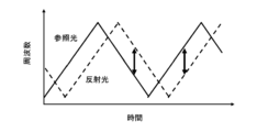
- FIG. 2 is a diagram schematically showing temporal changes in frequencies of reference light and reflected light when an object is stationary.
- 3 is a flow chart schematically showing an example of a measurement operation performed by a processing circuit in the first embodiment;
- FIG. 4 is a graph showing the spectrum of the detection signal in the comparative example.
- FIG. 5 is a diagram for explaining optical path lengths between components included in the measuring apparatus according to the first embodiment.
- FIG. 6 is a graph showing spectra of detection signals in the example.
- FIG. 7 is a block diagram schematically showing the configuration of a modification of the measurement device according to Embodiment 1.
- FIG. 8 is a block diagram schematically showing the configuration of a measuring device according to exemplary Embodiment 2 of the present disclosure.
- FIG. 9 is a block diagram schematically showing the configuration of a measuring device according to exemplary embodiment 3 of the present disclosure.
- FIG. 10 is a flow chart schematically showing an example of a measurement operation performed by a processing circuit in the third embodiment;
- FIG. 11 is a graph showing signal spectra in a comparative example.
- FIG. 12 is a diagram for explaining optical path lengths between components included in the measuring device according to the third embodiment.
- all or part of a circuit, unit, device, member or section, or all or part of a functional block in a block diagram is, for example, a semiconductor device, a semiconductor integrated circuit (IC), or an LSI (large scale integration). ) may be performed by one or more electronic circuits.
- An LSI or IC may be integrated on one chip, or may be configured by combining a plurality of chips.
- functional blocks other than memory elements may be integrated on one chip.
- LSIs or ICs may be called system LSIs, VLSIs (very large scale integration), or ULSIs (ultra large scale integration) depending on the degree of integration.
- a Field Programmable Gate Array (FPGA), which is programmed after the LSI is manufactured, or a reconfigurable logic device that can reconfigure the connection relationships inside the LSI or set up the circuit partitions inside the LSI can also be used for the same purpose.
- FPGA Field Programmable Gate Array
- circuits, units, devices, members or parts can be executed by software processing.
- the software is recorded on one or more non-transitory storage media, such as ROMs, optical discs, hard disk drives, etc., such that when the software is executed by a processor, the functions specified in the software are performed. It is executed by processors and peripherals.
- a system or apparatus may include one or more non-transitory storage media on which software is recorded, a processor, and required hardware devices such as interfaces.
- light refers not only to visible light (having a wavelength of about 400 nm to about 700 nm), but also to electromagnetic waves including ultraviolet rays (having a wavelength of about 10 nm to about 400 nm) and infrared rays (having a wavelength of about 700 nm to about 1 mm).
- ultraviolet light is referred to as “ultraviolet light”
- infrared light is also referred to as “infrared light”.
- FMCW-LiDAR technology achieves both a wide dynamic range and high resolution for distance, is less susceptible to disturbances, and can detect the speed of a fast-moving object.
- spot diameter of the light that irradiates the object can be made relatively small, and measurement data of the object can be obtained more accurately.
- Patent Literature 1 discloses a method of accurately measuring a distance by using internally scattered light generated by an optical antenna that emits light to the outside as a trigger for starting measurement.
- the internally scattered light disclosed in Patent Literature 1 can be used to improve the accuracy of distance measurement.
- the present inventor believes that a measuring device using FMCW-LiDAR technology has multiple scattered light that is considered to occur inside the optical component, in addition to the internally scattered light disclosed in Patent Document 1. We have found that such multiple scattered light may narrow the distance measurement range.
- a measurement device using FMCW-LiDAR technology, by appropriately designing the optical path length between internal components, the influence of multiple scattered light can be reduced, and the range measurement range can be expanded. becomes possible.
- a measuring device according to an embodiment of the present disclosure will be described below.
- the measuring device is a light source, and separates light from the light source into reference light and irradiation light for irradiating an object, and at least part of the irradiation light is generated by being reflected by the object.
- an interference optical system that generates interference light by causing interference between the reflected light and the reference light; at least one optical element that emits the at least part of the irradiation light and receives the reflected light; and the interference light a photodetector for detecting the
- the interference optical system includes an optical splitter having a first terminal for inputting the light from the light source, a second terminal for outputting the reference light, and a third terminal for outputting the irradiation light.
- the optical path length of the first path from the second terminal of the optical splitter to the photodetector is d1
- the optical path length of the second path from the third terminal of the optical splitter to the optical element is d2.
- the optical path length of the third path from the optical element to the photodetector is d3
- the optical path from the third terminal of the optical splitter to the photodetector via the noise optical path inside the interference optical system When the optical path length of the fourth path of is d4, the measuring device satisfy the relationship
- the influence of multiple scattered light generated inside the interference optical system can be reduced to widen the range of distance measurement.
- a measuring device is the measuring device according to the first item, wherein the interference optical system includes an optical circulator.
- the optical circulator is connected to the third terminal of the optical splitter and the at least one optical element.
- the photodetector is connected to the second terminal of the optical splitter and the optical circulator.
- the noise optical path is the path through the optical circulator.
- the influence of multiple scattered light generated inside the optical circulator can be reduced to widen the range of distance measurement.
- a measuring apparatus is the measuring apparatus according to the first item, wherein the interference optical system includes another optical splitter.
- the other optical splitter is connected to the third terminal of the optical splitter and the at least one optical element.
- the photodetector is connected to the second terminal of the optical splitter and the other optical splitter.
- the noise optical path is the path through the other optical splitter.
- the influence of multiple scattered light generated inside other light splitters can be reduced to widen the distance measurement range.
- a measuring device is the measuring device according to any one of the first to third items, wherein the at least one optical element includes a plurality of optical elements, and each of the plurality of optical elements includes the irradiation light. Emit part of the light.
- the measuring device satisfies the relationships of formulas (1) and (2) for each of the plurality of optical elements.
- the distance measurement range can be expanded.
- the measuring device is a light source, and separates light from the light source into reference light and irradiation light for irradiating an object, and at least part of the irradiation light is generated by being reflected by the object.
- an interference optical system that generates interference light by causing interference between the reflected light and the reference light; at least one optical element that emits the at least part of the irradiation light and receives the reflected light; and the interference light and another photodetector.
- the interference optical system includes an optical splitter having a first terminal for inputting the light from the light source, a second terminal for outputting the reference light, and a third terminal for outputting the irradiation light.
- the other photodetector detects a portion of the illumination light from the third terminal of the optical splitter to the optical element.
- the optical path length of the first path from the second terminal of the optical splitter to the photodetector is d1
- the optical path length of the second path from the third terminal of the optical splitter to the optical element is d2.
- d3 is the optical path length of the third path from the optical element to the photodetector;
- d5 is the optical path length of the fifth path from the third terminal of the optical splitter to the other photodetector;
- the measuring device satisfy the relationship
- the measuring device in the measuring device according to the first to fifth items, comprises a processing circuit for processing the signal output from the photodetector.
- the light source is capable of changing the frequency of the light.
- This measurement device can measure distance and/or velocity using FMCW-LiDAR technology.
- the measuring device is a light source, and separates light from the light source into reference light and irradiation light for irradiating an object, and at least part of the irradiation light is generated by being reflected by the object.
- an interference optical system that generates interference light by causing interference between the reflected light and the reference light; at least one optical element that emits the at least part of the irradiation light and receives the reflected light; and the interference light a photodetector for detecting the
- the measuring device defines a beat frequency f1 caused by interference between the light reflected by the optical element and reaching the photodetector in the irradiation light and the reference light, and the interference optical system in the irradiation light.
- the influence of multiple scattered light generated inside the interference optical system can be reduced to widen the range of distance measurement.
- the measuring device is the measuring device according to the seventh item, wherein the interference optical system inputs the at least part of the irradiation light to the at least one optical element, and the reflected light
- An optical circulator input to the photodetector is provided.
- the noise optical path is the path through the optical circulator.
- the influence of multiple scattered light generated inside the optical circulator can be reduced to widen the range of distance measurement.
- the measuring device is the measuring device according to the seventh item, wherein the interference optical system includes another optical splitter.
- the other light splitter inputs the at least part of the illumination light into the at least one optical element and inputs the reflected light into the photodetector.
- the noise optical path is the path through the other optical splitter.
- the influence of multiple scattered light generated inside other light splitters can be reduced to widen the distance measurement range.
- the at least one optical element includes a plurality of optical elements, and each of the plurality of optical elements emits part of the irradiation light.
- the measuring device satisfies the relationship of formula (4) for each of the plurality of optical elements.
- the distance measurement range can be expanded.
- the measuring device is a light source, and separates light from the light source into reference light and irradiation light for irradiating an object, and at least part of the irradiation light is generated by being reflected by the object.
- an interference optical system that generates interference light by causing interference between the reflected light and the reference light; at least one optical element that emits the at least part of the irradiation light and receives the reflected light; and the interference light and another photodetector for detecting part of the irradiation light from the interference optical system to the optical element.
- f1 is a beat frequency due to interference between the light reflected by the optical element and reaching the photodetector and the reference light, and the light is detected from the other photodetector in the irradiation light.
- the beat frequency due to the interference between the light reaching the instrument and the reference light is f3
- the measuring device satisfy the relationship
- a measuring device is the measuring device according to any one of the seventh to eleventh items, and includes a processing circuit for processing a signal output from the photodetector.
- the light source is capable of changing the frequency of the light.
- This measurement device can measure distance and/or velocity using FMCW-LiDAR technology.
- FIG. 1 is a block diagram schematically showing the configuration of a measuring device according to exemplary Embodiment 1 of the present disclosure.
- FIG. 1 shows an object 10 to be measured.
- the interference optical system 30 includes a first optical splitter 32a, a second optical splitter 32b, and an optical circulator .
- the bold lines shown in FIG. 1 represent optical fibers connecting the two components together.
- Solid lines with arrows shown in FIG. 1 represent transmission and reception of signals.
- a dashed line with an arrow shown in FIG. 1 represents the flow of light.
- the optical circulator 34 is thought to generate multiple scattered light, which may narrow the distance measurement range.
- the measurement apparatus 100A according to Embodiment 1 by appropriately designing the optical path length between the internal components, the influence of such multiple scattered light can be reduced, and the distance measurement range can be widened. . Specific conditions for reducing the influence of multiple scattered light will be detailed later.
- the constituent elements of the measuring device 100A will be described below.
- the light source 20 emits a laser beam 20L0.
- the light source 20 can change the frequency of the laser light 20L0.
- the frequency can be time-varying, for example, in a triangular or sawtooth shape with a constant time period.
- the time period may be, for example, 1 ⁇ s or more and 10 ms or less.
- the time period may vary.
- the change width of the frequency can be, for example, 100 MHz or more and 1 THz or less.
- the wavelength of the laser light 20L0 may be included in the near-infrared wavelength range of 700 nm or more and 2000 nm or less, for example.
- Sunlight has both near-infrared light and visible light, and the amount of near-infrared light is less than that of visible light. can be reduced.
- the wavelength of the laser light 20L0 does not necessarily have to be included in the wavelength range of near-infrared light.
- the wavelength of the laser light 20L0 may be included in the visible light wavelength range of 400 nm or more and 700 nm or less, or may be included in the ultraviolet light wavelength range.
- Light source 20 may comprise, for example, a distributed feedback laser diode or an external cavity laser diode. These laser diodes are inexpensive and small, are capable of single-mode oscillation, and can change the frequency of the laser light 20L0 according to the amount of current applied.
- a first light splitter 32 a included in the interference optical system 30 splits the laser light 20 L 0 emitted from the light source 20 into a reference light 20 L 1 and an illumination light 20 L 2 for illuminating the object 10 .
- the first optical splitter 32 a further inputs the reference light 20 L 1 to the second optical splitter 32 b and the irradiation light 20 L 2 to the optical circulator 34 .
- the first optical splitter 32a has a first terminal 32a1 to which the laser beam 20L0 is input, a second terminal 32a2 to output the reference beam 20L1, and a third terminal 32a3 to output the irradiation beam 20L2.
- the optical circulator 34 included in the interference optical system 30 inputs the irradiation light 20L2 to the optical element 40, and inputs the reflected light 20L3 generated by irradiating the object 10 with the irradiation light 20L2 to the second optical splitter 32b.
- the optical circulator 34 is connected to the third terminal 32 a 3 of the first optical splitter 32 a, the second optical splitter 32 b and the optical element 40 .
- the second optical splitter 32b included in the interference optical system 30 inputs to the photodetector 50 an interference light 20L4 obtained by superimposing and interfering the reference light 20L1 and the reflected light 20L3.
- the second optical splitter 32b like the first optical splitter 32a, has three terminals for inputting the reference light 20L1 and the reflected light 20L3 and for outputting the interference light 20L4.
- the optical element 40 emits the irradiation light 20L2 to the outside and receives the reflected light 20L3.
- the direction in which the irradiation light 20L2 is emitted from the optical element 40 is also referred to as "forward".
- the optical element 40 can be, for example, a collimator lens that collimates the illumination light 20L2.
- colllimate means not only the case of collimating the irradiation light 20L2 but also the case of reducing the spread of the irradiation light 20L2.
- the optical element 40 may be a diffraction grating that emits the irradiation light 20L2 to the outside as 0th-order diffracted light and/or ⁇ Nth-order diffracted light (N is a natural number).
- N is a natural number.
- the configuration of the measurement apparatus 100A can be simplified, and stable measurement can be achieved.
- the photodetector 50 detects the interference light 20L4.
- Photodetector 50 includes one or more photodetector elements.
- the photodetector outputs a signal corresponding to the intensity of the interference light 20L4.
- the photodetector 50 is connected to the second terminal 32a2 of the first optical splitter 32a and the optical circulator 34 via the second optical splitter 32b.
- a processing circuit 60 controls the operation of the light source 20 and the photodetector 50 .
- Processing circuitry 60 processes the signal output from photodetector 50 using FMCW-LiDAR technology.
- the processing circuit 60 generates and outputs measurement data regarding the distance and/or velocity of the object 10 based on the signal. Details of the operation of the processing circuit 60 will be described later.
- a computer program executed by the processing circuit 60 is stored in a memory 62 such as ROM or RAM (Random Access Memory).
- the measurement device 100A includes a processing device including processing circuitry 60 and memory 62 .
- the processing circuitry 60 and memory 62 may be integrated on one circuit board or provided on separate circuit boards.
- the control and signal processing functions of processing circuit 60 may be distributed over multiple circuits.
- the processor may be remotely located away from other components and control the operation of light source 20 and photodetector 50 via a wired or wireless communication network.
- FMCW-LiDAR technology Next, the FMCW-LiDAR technology will be briefly described with reference to FIG. Details of the FMCW-LiDAR technology are disclosed in Non-Patent Document 1, for example.
- FIG. 2 is a diagram schematically showing temporal changes in the frequencies of the reference light 20L1 and the reflected light 20L3 when the object 10 is stationary.
- a solid line represents the reference light 20L1 and a dashed line represents the reflected light 20L3.
- the frequency of the reference light 20L1 shown in FIG. 2 repeats triangular wave-like temporal changes. That is, the frequency of the reference light 20L1 repeats up-chirp and down-chirp. The increase in frequency during the up-chirp period and the decrease in frequency during the down-chirp period are equal to each other.
- the frequency of reflected light 20L3 is shifted in the positive direction along the time axis compared to the frequency of reference light 20L1.
- the amount of time shift of the reflected light 20L3 is equal to the time required for the irradiation light 20L2 to be emitted from the measuring device 100A to the outside, reflected by the object 10, and returned as the reflected light 20L3.
- the interference light 20L4 obtained by superimposing and interfering with the reference light 20L1 and the reflected light 20L3 has a frequency corresponding to the frequency difference between the frequency of the reflected light 20L3 and the frequency of the reference light 20L1.
- the double arrow shown in FIG. 2 represents the frequency difference between the two.
- the photodetector 50 outputs a signal indicating the intensity of the interference light 20L4.
- the signal is called a beat signal.
- the frequency of the beat signal, ie the beat frequency is equal to the above frequency difference.
- Processing circuitry 60 can generate measurement data about the distance of object 10 from the beat frequencies.
- the beat frequency during the up-chirp period and the beat frequency during the down-chirp period are equal to each other.
- ⁇ f is the increase or decrease in the frequency of light during the up-chirp period or the down-chirp period
- ⁇ t is the time required to change ⁇ f
- c is the speed of light
- the optical path length of the reference light 20L1 the optical path length of the irradiation light 20L2
- the optical path of the reflected light 20L3 Assuming that the difference from the total length is 2d, the beat frequency f beat in the up-chirp period or the down-chirp period is expressed by the following equation (6).
- the beat frequency f beat in Equation (6) is the time required for the irradiation light 20L2 to be emitted from the measurement device 100A to the outside, reflected by the object 10, and returned as the reflected light 20L3, at the time rate of change ⁇ f/ ⁇ t of the frequency. It is obtained by multiplying (2d/c).
- the frequency of the reflected light 20L3 is Doppler-shifted in the positive or negative direction along the frequency axis compared to the frequency of the reference light 20L1.
- the beat frequency during the up-chirp period and the beat frequency during the down-chirp period are different from each other. From the frequency difference and average of these beat frequencies, processing circuitry 60 can generate measured data regarding the velocity and distance of object 10, respectively.
- FIG. 3 is a flow chart schematically showing an example of the measurement operation performed by the processing circuit 60. As shown in FIG. The processing circuit 60 executes the operations of steps S101 to S103 shown in FIG.
- the processing circuit 60 causes the light source 20 to emit laser light 20L0 whose frequency changes with time.
- the processing circuit 60 causes the photodetector 50 to detect the interference light 20L4.
- the photodetector 50 outputs a signal corresponding to the intensity of the interference light 20L4.
- Processing circuitry 60 generates measurement data regarding the distance and/or velocity of object 10 based on the signal output from photodetector 50 .
- the above-described operation of the processing circuit 60 enables ranging and/or velocity measurement of the object 10.
- a light flow ⁇ is a flow of the reference light 20L1 from the second terminal 32a2 of the first optical splitter 32a to the photodetector 50.
- the light flow ⁇ is the flow from the third terminal 32 a 3 of the first optical splitter 32 a to the object 10 and the reflected light 20 L 3 from the object 10 to the photodetector 50 .
- the light flow ⁇ is a flow of part of the irradiation light 20L2 from the third terminal 32a3 of the first optical splitter 32a to the photodetector 50 after being reflected by the optical element 40. FIG. Such reflections occur at the interface between optical element 40 and air.
- the light flow ⁇ is the flow of another part of the irradiation light 20L2 from the third terminal 32a3 of the first optical splitter 32a to the photodetector 50 via the noise light path inside the optical circulator 34. .
- the noise light path is considered to be a path passing through the optical circulator 34, more specifically, a path along which leakage light of the irradiation light 20L2 toward the optical element 40 in the optical circulator 34 is multiple-scattered inside.
- the optical path length of the noise light path caused by internal multiple scattering is, for example, 10 times the shortest distance from the point where the irradiated light 20L2 is input to the point where the reflected light 20L3 is output in the optical circulator 34. 100 times longer.
- part of the irradiation light 20L2 is reflected by the optical element 40, and the other part is multiple-scattered inside the optical circulator 34. This is the remaining portion of the illumination light 20L2.
- the optical element 40 emits the irradiation light 20L2 to the outside.
- the range of the object 10 was measured by the following measuring device. Although the measurement apparatus has the components shown in FIG. 1, it does not satisfy the below-described conditions for reducing the influence of multiple scattered light.
- the distance from optical element 40 to object 10 was 1 m. As used herein, the distance from the optical element 40 to the object 10 refers to the distance from where the optical element 40 reflects said part of the illumination light 20L2 to where the object 10 reflects said remaining part of the illumination light 20L2. means the distance to a point.
- FIG. 4 is a graph showing the spectrum of the detection signal in the comparative example.
- the vertical and horizontal axes shown in FIG. 4 represent signal strength and frequency, respectively.
- the left end represents zero frequency and one division represents 250 MHz/512. Frequency corresponds to distance.
- the spectrum of the detection signal during the up-chirp period and the spectrum of the detection signal during the down-chirp period are superimposed. When the object 10 is stationary, the behavior of both is approximately the same.
- the peak ⁇ has a beat frequency between the reference beams 20L1, ie zero frequency.
- the peak ⁇ has a beat frequency obtained by interference between the reflected light 20L3 reflected by the object 10 and reaching the photodetector 50 and the reference light 20L1.
- the peak ⁇ has a beat frequency obtained by interference between the reference light 20L1 and the light reflected by the optical element 40 reaching the photodetector 50 in the irradiation light 20L2.
- Peak .delta. has a beat frequency that is
- the peak ⁇ is caused by the reflected light 20L3 reflected by the object 10.
- the peak ⁇ is noise and is caused by the light reflected by the optical element 40 in the irradiation light 20L2. Since the object 10 is located in front of the optical element 40, if the point where the optical element 40 reflects the illumination light 20L2 is taken as zero distance, the peak ⁇ serves as an indicator of the zero distance, albeit noise.
- the beat frequency of peak ⁇ is lower than the beat frequency of peak ⁇ , so peak ⁇ does not affect peak ⁇ . In the example shown in FIG. 4, the difference between the beat frequency of peak ⁇ and the beat frequency of peak ⁇ corresponds to a distance of 1 m.
- the peak ⁇ is noise and is caused by multiple scattered light generated inside the optical circulator 34 .
- the beat frequency of peak ⁇ is higher than the beat frequency of peak ⁇ , and the difference between them corresponds to a distance of 3.5 m.
- the peak ⁇ and the peak ⁇ are close to each other, making it difficult to determine which peak is the peak ⁇ .
- the distance to the object 10 cannot be accurately measured, resulting in a narrower distance measurement range.
- FIG. 5 is a diagram for explaining optical path lengths between components included in the measurement apparatus 100A according to the first embodiment.
- the optical path length of the first path from the second terminal 32a2 of the first optical splitter 32a to the photodetector 50 be a first optical path length d1.
- the optical path length of the second path from the third terminal 32a3 of the first optical splitter 32a to the optical element 40 is defined as a second optical path length d2.
- the optical path length of the third path from the optical element 40 to the photodetector 50 be a third optical path length d3.
- the optical path length of the fourth path from the third terminal 32a3 of the first optical splitter 32a to the photodetector 50 via the noise optical path inside the interference optical system 30, more specifically, inside the optical circulator 34, is A fourth optical path length is d4. Let the round-trip distance between the optical element 40 and the object 10 be 2L.
- the optical path length of the light flow ⁇ is the fourth optical path length d4.
- Equation (7) means that the optical path length D of the light flow ⁇ is longer than the first optical path length d1 of the light flow ⁇ .
- Equation (8) implies that the beat frequency of peak ⁇ is higher than the beat frequency of peak ⁇ .
- the fourth optical path length d4 of the light flow ⁇ may be longer or shorter than the first optical path length d1 of the light flow ⁇ . Since the optical path length of the light flow ⁇ is longer than the optical path length D of the light flow ⁇ by 2L, the beat frequency of the peak ⁇ is higher than the beat frequency of the peak ⁇ . Therefore, peak ⁇ does not affect peak ⁇ .
- Equation (9) may be used where f1 is the beat frequency of peak ⁇ and f2 is the beat frequency of peak ⁇ .
- FIG. 6 is a graph showing spectra of detection signals in the example.
- the vertical axis and horizontal axis shown in FIG. 6 are the same as the vertical axis and horizontal axis shown in FIG. 4, respectively.
- the beat frequency of peak ⁇ is higher than the beat frequency of peak ⁇
- the beat frequency of peak ⁇ is higher than the beat frequency of peak ⁇ . Therefore, in the example, the peak ⁇ and the peak ⁇ do not come close to each other, and the distance measurement range of the object 10 can be wider than in the comparative example.
- a method for calibrating the measuring device 100A according to the first embodiment is as follows. In a configuration in which the distance from the optical element 40 to the object 10 is, for example, 1 m, and the reflectance of the object 10 with respect to the irradiation light 20L2 is, for example, 10% or more, the distance of the object 10 is measured.
- Calibration object 10 can be, for example, a silver diffuser.
- the optical path lengths D and d1 are adjusted so that the relationships of equations (7) to (9) are satisfied in this configuration.
- the optical path length D can be adjusted, for example, by increasing or decreasing the length of the optical fiber connecting the optical circulator 34 and the optical element 40 to each other.
- the first optical path length d1 can be adjusted, for example, by increasing or decreasing the length of the optical fiber connecting the first optical splitter 32a and the second optical splitter 32b. If the optical fiber is wound, a large space is not required even if the optical path length D and/or d1 is lengthened.
- the optical path length from the third terminal 32a3 of the first optical splitter 32a to the photodetector 50 via the longest noise optical path inside the interference optical system 30 is selected as the fourth optical path length d4.
- the highest beat frequency among beat frequencies of a plurality of peaks ⁇ may be selected as the beat frequency f2.
- the beat frequency in the up-chirp period and the down-chirp period shown in FIG. A shift of the Doppler frequency fd results in f0 ⁇ fd.
- the distance L from the optical element 40 to the object 10 is adjusted so that f0 ⁇ fd ⁇ f1.
- FIG. 7 is a block diagram schematically showing the configuration of a modification of the measurement device according to Embodiment 1.
- FIG. A measuring apparatus 110A shown in FIG. 7 differs from the measuring apparatus 100A shown in FIG. 1 in that the interference optical system 30 includes a third optical splitter 32c instead of the optical circulator 34 shown in FIG.
- the third optical splitter 32c like the optical circulator 34, is connected to the third terminal 32a3 of the first optical splitter 32a, the second optical splitter 32b, and the optical element .
- the noise optical path is the path through the optical circulator 34.
- the first optical splitter 32a is also called “optical splitter”
- the third optical splitter 32c is also called “another optical splitter”.
- the third optical splitter 32 c inputs the irradiation light 20 L 2 to the optical element 40 .
- the optical circulator 34 inputs the reflected light 20L3 to the second optical splitter 32b.
- part of the reflected light 20L3 may return to the light source 20 via the first light splitter 32a.
- Such return light may be removed by providing an optical isolator between the light source 20 and the first optical splitter 32a.
- the distance measurement range can be widened in the same manner as in the measuring device 100A.
- FIG. 8 is a block diagram schematically showing the configuration of a measuring device according to exemplary Embodiment 2 of the present disclosure.
- the object 10 shown in FIG. 1 has been omitted.
- the measurement apparatus 100B shown in FIG. 8 is different from the measurement apparatus 100A shown in FIG. 1 in that the measurement apparatus 100B includes the fourth optical splitter 32d and the first optical element instead of the single optical element 40 shown in FIG. 40a, a second optical element 40b, and a third optical element 40c.
- the first optical element 40a, the second optical element 40b, and the third optical element 40c are also collectively referred to as "optical elements 40a to 40c.”
- the fourth optical splitter 32 d is connected to the optical circulator 34 .
- the optical elements 40a-40c are connected to a fourth optical splitter 32d. It can also be said that the optical elements 40a-40c are connected to the optical circulator 34 via the fourth optical splitter 32d.
- the fourth light splitter 32d splits the irradiation light 20L2 into first to third lights.
- the optical elements 40a to 40c emit the first to third lights to the outside, respectively, and receive the first to third reflected lights generated when the first to third lights are reflected by the object 10, respectively.
- Each of the first to third lights is part of the illumination light 20L2.
- the outputs of the first to third lights may be equal to each other or may be different from each other.
- the number of branches of the fourth optical splitter 32d is not limited, and is two or more. The same applies to the number of optical elements 40a-40c.
- the optical path lengths of the three paths from the fourth optical splitter 32d to the optical elements 40a to 40c may be equal or different.
- the zero distances of the first to third lights emitted to the outside from the optical elements 40a to 40c can be different from each other. Therefore, in the spectrum of the detection signal, first to third frequency bands corresponding to the first to third lights emitted to the outside can be assigned, respectively. As a result, from the frequency band in which the peak appears, it is possible to know which of the first to third lights used to measure the distance to the object 10 .
- the measuring apparatus 100B according to the second embodiment also has a distance measurement range as in the measuring apparatus 100A according to the first embodiment. can be expanded.
- the aforementioned second and third paths pass through the fourth optical splitter 32d.
- the optical elements 40a to 40c if the optical element having the shortest total D of the second optical path length d2 and the third optical path length d3 described above satisfies the relationships of formulas (7) to (9), the remaining optical elements also necessarily satisfy the relationships of formulas (7) to (9).
- the optical element with the shortest total D of the second optical path length d2 and the third optical path length d3 is the first optical element 40a.
- FIG. 9 is a block diagram schematically showing the configuration of a measuring device according to exemplary embodiment 3 of the present disclosure.
- the object 10 shown in FIG. 1 has been omitted.
- a measuring apparatus 100C shown in FIG. 9 differs from the measuring apparatus 100A shown in FIG. 1 in that the measuring apparatus 100C includes a fifth optical splitter 32e and a second photodetector 50b.
- the fifth optical splitter 32e is positioned between the optical circulator 34 and the optical element 40 and is connected to both.
- the second photodetector 50b is connected to the fifth optical splitter 32e.
- the optical element 40 is connected to the optical circulator 34 via the fifth optical splitter 32e.
- the first photodetector 50a is the same as the photodetector 50 shown in FIG. In this specification, the first photodetector 50a is also called “photodetector”, and the second photodetector 50b is also called “another photodetector”.
- the fifth optical splitter 32e inputs part of the irradiation light 20L2 from the third terminal 32a3 of the first optical splitter 32a to the optical element 40 as the monitor light 20L5 into the second photodetector 50b.
- the second photodetector 50b detects the monitor light 20L5.
- the output of the monitor light 20L5 can be, for example, 5% or less of the output of the irradiation light 20L2 emitted from the optical element 40 to the outside.
- the detection signal of the second photodetector 50b can be used for various purposes.
- the detection signal of the second photodetector 50b may be used as a monitor signal for controlling the operation of the light source 20 so that the emitted light 20L2 does not exceed the eye-safe reference value.
- the eye-safe reference value can be, for example, 10 mW.
- the frequency of the laser light 20L0 emitted from the light source 20 is periodically modulated. If a laser diode capable of emitting high-power laser light is used as the light source 20, such frequency modulation can be stably performed. However, since the light source 20 can emit high-power laser light, there is a possibility that the output of the laser light 20L0 may exceed the eye-safe reference value due to, for example, a failure or malfunction.
- the processing circuit 60 controls the operation of the light source 20 based on the detection signal from the second photodetector 50b so that the output of the laser light 20L0 does not exceed the eye-safe reference value.
- FIG. 10 is a flow chart schematically showing an example of the measurement operation performed by the processing circuit 60. As shown in FIG. The processing circuit 60 executes the operations of steps S201 to S206 shown in FIG.
- Steps S201, S204, and S205 The operations of steps S201, S204, and S205 are respectively the same as the operations of steps S101 to S103 shown in FIG.
- Step S202> The processing circuit 60 causes the second photodetector 50b to detect the monitor light 20L5.
- Step S203 Based on the output of the monitor light 20L5, the processing circuit 60 determines whether the output of the irradiation light 20L2 emitted from the optical element 40 to the outside is equal to or less than the eye-safe reference value. In calibrating the measurement apparatus 100C, by associating the output of the monitor light 20L5 with the output of the irradiation light 20L2 emitted to the outside, the output of the irradiation light 20L2 to be emitted to the outside can be known from the output of the monitor light 20L5. If the determination is Yes, processing circuitry 60 performs the operations of steps S204 and S205. If the determination is No, processing circuitry 60 performs the operation of step S206.
- the processing circuit 60 causes the light source 20 to stop emitting the laser light 20L0.
- the object 10 can be measured for distance and/or velocity by the irradiation light 20L2 whose output is equal to or less than the eye-safe reference value.
- FIG. 9 Flow of light in measuring device 100C
- the light flow ⁇ shown in FIG. 9 exists in the measuring device 100C shown in FIG.
- the light flows ⁇ and ⁇ pass through the fifth optical splitter 32e shown in FIG.
- the light flow ⁇ is the flow of the irradiation light 20L2 from the third terminal 32a3 of the first light splitter 32a to the first light detector 50a after being reflected by the second light detector 50b.
- the light flow ⁇ causes noise in the detected signal.
- the light flow ⁇ may narrow the distance measurement range even if the relationships of Expressions (7) to (9) are satisfied. explain.
- the range of the object 10 was measured by the following measuring device.
- the measurement apparatus has the components shown in FIG. 9, it does not satisfy the below-described conditions for reducing the influence of light reflected by the second photodetector 50b.
- FIG. 11 is a graph showing the spectrum of the detected signal in the comparative example.
- the vertical axis and horizontal axis shown in FIG. 11 are the same as the vertical axis and horizontal axis shown in FIG. 4, respectively.
- multiple peaks appear in the spectrum of the detection signal.
- the arrows shown in FIG. 11 represent representative five peaks among them.
- the peaks ⁇ to ⁇ are as described with reference to FIG.
- the peak ⁇ has a beat frequency obtained by interference between the light from the second photodetector 50b to the first photodetector 50a in the irradiation light 20L2 and the reference light 20L1.
- the peak ⁇ is noise and is caused by the light reflected by the second photodetector 50b in the illumination light 20L2.
- the beat frequency of peak ⁇ is higher than the beat frequency of peak ⁇ , and the beat frequency of peak ⁇ is higher than the beat frequency of peak ⁇ because the relationships of equations (7) through (9) are satisfied.
- Peak ⁇ is an index of zero distance.
- the beat frequency of peak ⁇ is higher than the beat frequency of peak ⁇ . Therefore, when the peak ⁇ and the peak ⁇ are close to each other, there arises a problem that the distance of the object 10 cannot be accurately measured in the frequency band near the peak ⁇ .
- FIG. 12 is a diagram for explaining optical path lengths between components included in the measuring device 100C according to the third embodiment. Let the optical path length of the fifth path from the third terminal 32a3 of the first optical splitter 32a to the second photodetector 50b be a fifth optical path length d5. Let the optical path length of the sixth path from the second photodetector 50b to the first photodetector 50a be a sixth optical path length d6.
- the condition that the above optical path length satisfies in the measurement apparatus 100C according to the third embodiment is represented by the following equation (10).
- Equation (8) implies that the beat frequency of peak ⁇ is higher than the beat frequency of peak ⁇ .
- Equation (11) may be used with the beat frequency of peak ⁇ set to f3.
- the relationships of the equations (10) and (11) are satisfied.
- the influence of the light reflected by the second photodetector 50b can be reduced, and the distance measurement range can be widened.
- Optical fibers are used for connection between components in the measuring devices 100A, 110A, 100B, and 100C described above.
- optical waveguides may be used for connection between components.
- Optical waveguides may be formed by patterning semiconductor or dielectric materials using microfabrication techniques. Also, each component and the optical waveguide may be integrated on the same substrate.
- the components of the measuring devices 100A, 110A, 100B, and 100C described above may be combined arbitrarily as long as there is no contradiction.
- the measuring device can be used, for example, for a ranging system mounted on a vehicle such as an automobile, UAV (Unmanned Aerial Vehicle), or AGV (Automated Guided Vehicle), or for vehicle detection.
- a vehicle such as an automobile, UAV (Unmanned Aerial Vehicle), or AGV (Automated Guided Vehicle), or for vehicle detection.
- UAV Unmanned Aerial Vehicle
- AGV Automatic Guided Vehicle
Landscapes
- Physics & Mathematics (AREA)
- Engineering & Computer Science (AREA)
- Electromagnetism (AREA)
- Computer Networks & Wireless Communication (AREA)
- General Physics & Mathematics (AREA)
- Radar, Positioning & Navigation (AREA)
- Remote Sensing (AREA)
- Optical Radar Systems And Details Thereof (AREA)
Priority Applications (4)
| Application Number | Priority Date | Filing Date | Title |
|---|---|---|---|
| EP22924045.2A EP4471452A4 (en) | 2022-01-27 | 2022-11-09 | MEASURING DEVICE |
| JP2023576634A JPWO2023145191A1 (https=) | 2022-01-27 | 2022-11-09 | |
| CN202280088238.7A CN118525220A (zh) | 2022-01-27 | 2022-11-09 | 计测装置 |
| US18/755,623 US20240345221A1 (en) | 2022-01-27 | 2024-06-26 | Measurement device |
Applications Claiming Priority (2)
| Application Number | Priority Date | Filing Date | Title |
|---|---|---|---|
| JP2022010910 | 2022-01-27 | ||
| JP2022-010910 | 2022-01-27 |
Related Child Applications (1)
| Application Number | Title | Priority Date | Filing Date |
|---|---|---|---|
| US18/755,623 Continuation US20240345221A1 (en) | 2022-01-27 | 2024-06-26 | Measurement device |
Publications (1)
| Publication Number | Publication Date |
|---|---|
| WO2023145191A1 true WO2023145191A1 (ja) | 2023-08-03 |
Family
ID=87471361
Family Applications (1)
| Application Number | Title | Priority Date | Filing Date |
|---|---|---|---|
| PCT/JP2022/041785 Ceased WO2023145191A1 (ja) | 2022-01-27 | 2022-11-09 | 計測装置 |
Country Status (5)
| Country | Link |
|---|---|
| US (1) | US20240345221A1 (https=) |
| EP (1) | EP4471452A4 (https=) |
| JP (1) | JPWO2023145191A1 (https=) |
| CN (1) | CN118525220A (https=) |
| WO (1) | WO2023145191A1 (https=) |
Cited By (1)
| Publication number | Priority date | Publication date | Assignee | Title |
|---|---|---|---|---|
| WO2025154380A1 (ja) * | 2024-01-17 | 2025-07-24 | パナソニックIpマネジメント株式会社 | 計測装置 |
Families Citing this family (1)
| Publication number | Priority date | Publication date | Assignee | Title |
|---|---|---|---|---|
| JPWO2023188478A1 (https=) * | 2022-03-30 | 2023-10-05 |
Citations (4)
| Publication number | Priority date | Publication date | Assignee | Title |
|---|---|---|---|---|
| JP2009525838A (ja) * | 2006-02-08 | 2009-07-16 | ザ ジェネラル ホスピタル コーポレイション | 光学顕微鏡法を用いて解剖学的サンプルに関わる情報を取得するための方法、装置およびシステム |
| JP2010127840A (ja) * | 2008-11-28 | 2010-06-10 | Mitsubishi Electric Corp | 光波レーダ装置 |
| JP6274368B1 (ja) | 2017-04-13 | 2018-02-07 | 三菱電機株式会社 | レーザレーダ装置 |
| JP2019045200A (ja) | 2017-08-30 | 2019-03-22 | 国立研究開発法人産業技術総合研究所 | 光学的距離測定装置および測定方法 |
Family Cites Families (3)
| Publication number | Priority date | Publication date | Assignee | Title |
|---|---|---|---|---|
| US11249190B2 (en) * | 2017-06-20 | 2022-02-15 | Mitsubishi Electric Corporation | Laser radar device and method for controlling frequency modulation |
| WO2019130472A1 (ja) * | 2017-12-27 | 2019-07-04 | 三菱電機株式会社 | レーザレーダ装置 |
| US20210349213A1 (en) * | 2020-05-05 | 2021-11-11 | Ivan Grudinin | Arbitrary optical waveform generation utilizing frequency discriminators |
-
2022
- 2022-11-09 JP JP2023576634A patent/JPWO2023145191A1/ja active Pending
- 2022-11-09 EP EP22924045.2A patent/EP4471452A4/en not_active Withdrawn
- 2022-11-09 WO PCT/JP2022/041785 patent/WO2023145191A1/ja not_active Ceased
- 2022-11-09 CN CN202280088238.7A patent/CN118525220A/zh active Pending
-
2024
- 2024-06-26 US US18/755,623 patent/US20240345221A1/en active Pending
Patent Citations (4)
| Publication number | Priority date | Publication date | Assignee | Title |
|---|---|---|---|---|
| JP2009525838A (ja) * | 2006-02-08 | 2009-07-16 | ザ ジェネラル ホスピタル コーポレイション | 光学顕微鏡法を用いて解剖学的サンプルに関わる情報を取得するための方法、装置およびシステム |
| JP2010127840A (ja) * | 2008-11-28 | 2010-06-10 | Mitsubishi Electric Corp | 光波レーダ装置 |
| JP6274368B1 (ja) | 2017-04-13 | 2018-02-07 | 三菱電機株式会社 | レーザレーダ装置 |
| JP2019045200A (ja) | 2017-08-30 | 2019-03-22 | 国立研究開発法人産業技術総合研究所 | 光学的距離測定装置および測定方法 |
Non-Patent Citations (2)
| Title |
|---|
| CHRISTOPHER V. P., OFC, 2016 |
| See also references of EP4471452A4 |
Cited By (1)
| Publication number | Priority date | Publication date | Assignee | Title |
|---|---|---|---|---|
| WO2025154380A1 (ja) * | 2024-01-17 | 2025-07-24 | パナソニックIpマネジメント株式会社 | 計測装置 |
Also Published As
| Publication number | Publication date |
|---|---|
| US20240345221A1 (en) | 2024-10-17 |
| CN118525220A (zh) | 2024-08-20 |
| EP4471452A1 (en) | 2024-12-04 |
| JPWO2023145191A1 (https=) | 2023-08-03 |
| EP4471452A4 (en) | 2025-05-14 |
Similar Documents
| Publication | Publication Date | Title |
|---|---|---|
| US20240345221A1 (en) | Measurement device | |
| US20200400822A1 (en) | Laser radar device | |
| US5532813A (en) | Optical distance meter and light source device used for the same | |
| CN110268280A (zh) | 双频fmcw雷达和方法 | |
| WO2003038446A1 (en) | Optical device and method for measuring velocity | |
| WO2010058322A1 (en) | Laser self-mixing differential doppler velocimetry and vibrometry | |
| JP6782470B2 (ja) | 計測装置及び計測方法 | |
| EP3214402B1 (en) | Measuring apparatus for measuring vibration or displacement and method for measuring vibration or displacement | |
| JP2013207276A (ja) | レーザモジュール | |
| CN1734287B (zh) | 绝对距离测量设备 | |
| EP4249947B1 (en) | Electro-optical distance meter | |
| CN118017340A (zh) | 光学滤波装置、激光雷达设备和激光光束质量改善方法 | |
| US20250004114A1 (en) | Measurement device | |
| WO2025154381A1 (ja) | 計測装置 | |
| US20260036695A1 (en) | Measurement apparatus for measuring distance to physical object and/or velocity of physical object | |
| WO2025154380A1 (ja) | 計測装置 | |
| WO2024224691A1 (ja) | 対象物までの距離および/または対象物の速度を計測する計測装置 | |
| US12379494B2 (en) | Optical distance measurement device and machining device | |
| EP4535029A1 (en) | Measurement device | |
| US20210396854A1 (en) | Lidar using a multicore fiber | |
| KR102741580B1 (ko) | 광지연 다중 발생 기준단을 이용하여 측정 거리를 향상시키는 광간섭계 측정 장치 | |
| KR102908351B1 (ko) | Opll을 이용한 광 신호의 주파수 제어 방법과 그 제어 방법이 적용된 fmcw 라이다 및 그 제어 방법이 적용된 fmcw 라이다를 이용한 차량 자율주행 방법 | |
| US20240004042A1 (en) | Measuring device and non-transitory computer-readable medium | |
| WO2025169637A1 (ja) | 計測装置 | |
| WO2025142188A1 (ja) | 計測装置 |
Legal Events
| Date | Code | Title | Description |
|---|---|---|---|
| 121 | Ep: the epo has been informed by wipo that ep was designated in this application |
Ref document number: 22924045 Country of ref document: EP Kind code of ref document: A1 |
|
| ENP | Entry into the national phase |
Ref document number: 2023576634 Country of ref document: JP Kind code of ref document: A |
|
| WWE | Wipo information: entry into national phase |
Ref document number: 202280088238.7 Country of ref document: CN |
|
| NENP | Non-entry into the national phase |
Ref country code: DE |
|
| ENP | Entry into the national phase |
Ref document number: 2022924045 Country of ref document: EP Effective date: 20240827 |
|
| WWW | Wipo information: withdrawn in national office |
Ref document number: 2022924045 Country of ref document: EP |