WO2023144919A1 - 回転子、電動機、送風機及び空気調和装置 - Google Patents
回転子、電動機、送風機及び空気調和装置 Download PDFInfo
- Publication number
- WO2023144919A1 WO2023144919A1 PCT/JP2022/002861 JP2022002861W WO2023144919A1 WO 2023144919 A1 WO2023144919 A1 WO 2023144919A1 JP 2022002861 W JP2022002861 W JP 2022002861W WO 2023144919 A1 WO2023144919 A1 WO 2023144919A1
- Authority
- WO
- WIPO (PCT)
- Prior art keywords
- resin magnet
- rotor
- resin
- magnet
- rare earth
- Prior art date
- Legal status (The legal status is an assumption and is not a legal conclusion. Google has not performed a legal analysis and makes no representation as to the accuracy of the status listed.)
- Ceased
Links
Images


Classifications
-
- H—ELECTRICITY
- H02—GENERATION; CONVERSION OR DISTRIBUTION OF ELECTRIC POWER
- H02K—DYNAMO-ELECTRIC MACHINES
- H02K1/00—Details of the magnetic circuit
- H02K1/06—Details of the magnetic circuit characterised by the shape, form or construction
- H02K1/22—Rotating parts of the magnetic circuit
- H02K1/27—Rotor cores with permanent magnets
- H02K1/2706—Inner rotors
- H02K1/272—Inner rotors the magnetisation axis of the magnets being perpendicular to the rotor axis
- H02K1/2726—Inner rotors the magnetisation axis of the magnets being perpendicular to the rotor axis the rotor consisting of a single magnet or two or more axially juxtaposed single magnets
- H02K1/2733—Annular magnets
-
- H—ELECTRICITY
- H02—GENERATION; CONVERSION OR DISTRIBUTION OF ELECTRIC POWER
- H02K—DYNAMO-ELECTRIC MACHINES
- H02K1/00—Details of the magnetic circuit
- H02K1/02—Details of the magnetic circuit characterised by the magnetic material
-
- H—ELECTRICITY
- H02—GENERATION; CONVERSION OR DISTRIBUTION OF ELECTRIC POWER
- H02K—DYNAMO-ELECTRIC MACHINES
- H02K1/00—Details of the magnetic circuit
- H02K1/06—Details of the magnetic circuit characterised by the shape, form or construction
- H02K1/22—Rotating parts of the magnetic circuit
- H02K1/27—Rotor cores with permanent magnets
- H02K1/2706—Inner rotors
- H02K1/272—Inner rotors the magnetisation axis of the magnets being perpendicular to the rotor axis
- H02K1/274—Inner rotors the magnetisation axis of the magnets being perpendicular to the rotor axis the rotor consisting of two or more circumferentially positioned magnets
- H02K1/2746—Inner rotors the magnetisation axis of the magnets being perpendicular to the rotor axis the rotor consisting of two or more circumferentially positioned magnets the rotor consisting of magnets arranged with the same polarity, e.g. consequent pole type
-
- H—ELECTRICITY
- H02—GENERATION; CONVERSION OR DISTRIBUTION OF ELECTRIC POWER
- H02K—DYNAMO-ELECTRIC MACHINES
- H02K1/00—Details of the magnetic circuit
- H02K1/06—Details of the magnetic circuit characterised by the shape, form or construction
- H02K1/22—Rotating parts of the magnetic circuit
- H02K1/27—Rotor cores with permanent magnets
- H02K1/2706—Inner rotors
- H02K1/272—Inner rotors the magnetisation axis of the magnets being perpendicular to the rotor axis
- H02K1/274—Inner rotors the magnetisation axis of the magnets being perpendicular to the rotor axis the rotor consisting of two or more circumferentially positioned magnets
- H02K1/2753—Inner rotors the magnetisation axis of the magnets being perpendicular to the rotor axis the rotor consisting of two or more circumferentially positioned magnets the rotor consisting of magnets or groups of magnets arranged with alternating polarity
- H02K1/276—Magnets embedded in the magnetic core, e.g. interior permanent magnets [IPM]
- H02K1/2766—Magnets embedded in the magnetic core, e.g. interior permanent magnets [IPM] having a flux concentration effect
-
- H—ELECTRICITY
- H02—GENERATION; CONVERSION OR DISTRIBUTION OF ELECTRIC POWER
- H02K—DYNAMO-ELECTRIC MACHINES
- H02K1/00—Details of the magnetic circuit
- H02K1/06—Details of the magnetic circuit characterised by the shape, form or construction
- H02K1/22—Rotating parts of the magnetic circuit
- H02K1/27—Rotor cores with permanent magnets
- H02K1/2706—Inner rotors
- H02K1/272—Inner rotors the magnetisation axis of the magnets being perpendicular to the rotor axis
- H02K1/274—Inner rotors the magnetisation axis of the magnets being perpendicular to the rotor axis the rotor consisting of two or more circumferentially positioned magnets
- H02K1/2753—Inner rotors the magnetisation axis of the magnets being perpendicular to the rotor axis the rotor consisting of two or more circumferentially positioned magnets the rotor consisting of magnets or groups of magnets arranged with alternating polarity
- H02K1/278—Surface mounted magnets; Inset magnets
- H02K1/2783—Surface mounted magnets; Inset magnets with magnets arranged in Halbach arrays
-
- H—ELECTRICITY
- H02—GENERATION; CONVERSION OR DISTRIBUTION OF ELECTRIC POWER
- H02K—DYNAMO-ELECTRIC MACHINES
- H02K15/00—Processes or apparatus specially adapted for manufacturing, assembling, maintaining or repairing of dynamo-electric machines
- H02K15/02—Processes or apparatus specially adapted for manufacturing, assembling, maintaining or repairing of dynamo-electric machines of stator or rotor bodies
- H02K15/03—Processes or apparatus specially adapted for manufacturing, assembling, maintaining or repairing of dynamo-electric machines of stator or rotor bodies having permanent magnets
-
- H—ELECTRICITY
- H02—GENERATION; CONVERSION OR DISTRIBUTION OF ELECTRIC POWER
- H02K—DYNAMO-ELECTRIC MACHINES
- H02K7/00—Arrangements for handling mechanical energy structurally associated with dynamo-electric machines, e.g. structural association with mechanical driving motors or auxiliary dynamo-electric machines
- H02K7/14—Structural association with mechanical loads, e.g. with hand-held machine tools or fans
-
- H—ELECTRICITY
- H02—GENERATION; CONVERSION OR DISTRIBUTION OF ELECTRIC POWER
- H02K—DYNAMO-ELECTRIC MACHINES
- H02K2213/00—Specific aspects, not otherwise provided for and not covered by codes H02K2201/00 - H02K2211/00
- H02K2213/03—Machines characterised by numerical values, ranges, mathematical expressions or similar information
Definitions
- the present disclosure relates to rotors, electric motors, fans, and air conditioners.
- the rotors described in Patent Documents 1 and 2 have ferrite resin magnets and rare earth resin magnets arranged on the outer peripheral surface of the ferrite resin magnets.
- the shape of the rare earth resin magnets of Patent Documents 1 and 2 when viewed in the axial direction is annular.
- the rotor described in Patent Document 3 has a ferrite resin magnet and a plurality of rare earth resin magnets arranged side by side on the outer peripheral surface of the ferrite resin magnet. Therefore, the cost of the rotor of Patent Document 3 is lower than that of the rotors of Patent Documents 1 and 2.
- the present disclosure aims to prevent the occurrence of distortion of the effective magnetic flux.
- a rotor includes a rotating shaft, a first resin magnet supported by the rotating shaft, and a first outer peripheral surface that is a radially outward surface of the first resin magnet. and a plurality of second resin magnets having magnetic poles stronger than the magnetic poles of the first resin magnets, and a first resin magnet having a length in the axial direction of the rotating shaft of the first resin magnets When the length is L1 and the second length, which is the axial length of each second resin magnet of the plurality of second resin magnets, is L2, L1>L2.
- An electric motor according to another aspect of the present disclosure has the above-described rotor and stator.
- a fan according to another aspect of the present disclosure includes the electric motor described above and an impeller driven by the electric motor.
- An air conditioner includes an indoor unit and an outdoor unit connected to the indoor unit, and at least one of the indoor unit and the outdoor unit includes the electric motor described above. .
- FIG. 1 is a plan view showing a configuration of an electric motor according to Embodiment 1;
- FIG. 1 is a partial cross-sectional view showing the configuration of an electric motor according to Embodiment 1;
- FIG. FIG. 2 is a side view showing the configuration of the rotor shown in FIG. 1;
- FIG. 2 is an enlarged plan view showing the configuration of the rotor shown in FIG. 1;
- FIG. 5 is a plan view showing the structure of the ferrite resin magnet shown in FIG. 4;
- FIG. 5 is a cross-sectional view of the rotor shown in FIG. 4 taken along line B6-B6;
- 8A is a plan view showing the configuration of a rotor according to Comparative Example 1.
- FIG. 1 is a plan view showing a configuration of an electric motor according to Embodiment 1;
- FIG. 1 is a partial cross-sectional view showing the configuration of an electric motor according to Embodiment 1;
- FIG. FIG. 2 is a side view showing
- FIG. (B) is a side view showing a configuration of a rotor according to Comparative Example 1.
- FIG. (A) is a plan view showing a configuration of a rotor according to Comparative Example 2.
- FIG. (B) is a side view showing the configuration of a rotor according to Comparative Example 2.
- FIG. 12 is a graph showing the rate of increase in interlinkage magnetic flux with respect to the overhang ratio of the ferrite resin magnet shown in FIG.
- FIG. 11; 4 is a flow chart showing a manufacturing process of the rotor according to Embodiment 1.
- FIG. FIG. 8 is a plan view showing a part of the configuration of a rotor according to Embodiment 2;
- FIG. 11 is a side view showing the configuration of a rotor according to Embodiment 3;
- FIG. 16 is a cross-sectional view of the rotor shown in FIG. 15 taken along line B16-B16;
- FIG. 16 is a sectional view of the rotor shown in FIG. 15 taken along line B17-B17;
- FIG. 18 is a cross-sectional view of the rotor shown in FIG. 17 taken along line B18-B18;
- FIG. 11 is a plan view showing the configuration of a rotor according to Embodiment 4;
- FIG. 20 is a cross-sectional view of the rotor shown in FIG. 19 taken along line B20-B20;
- FIG. 11 is a plan view showing the configuration of a rotor according to Embodiment 5;
- FIG. 22 is a cross-sectional view of the rotor shown in FIG. 21 taken along line B22-B22;
- FIG. 11 is a cross-sectional view schematically showing the configuration of a rotor according to a modification of Embodiment 5;
- FIG. 24 is a cross-sectional view of the rotor shown in FIG. 23 taken along line B24-B24;
- FIG. 12 is a diagram schematically showing the configuration of a blower according to Embodiment 6;
- FIG. 11 is a diagram schematically showing the configuration of an air conditioner according to Embodiment 7;
- part of the drawing shows an xyz orthogonal coordinate system.
- the z-axis is the coordinate axis parallel to the axis A of the rotor.
- the x-axis is a coordinate axis orthogonal to the z-axis.
- the y-axis is a coordinate axis orthogonal to both the x-axis and the z-axis.
- FIG. 1 is a plan view showing the configuration of electric motor 100 according to Embodiment 1.
- FIG. 2 is a partial cross-sectional view showing the configuration of electric motor 100 according to the first embodiment.
- Electric motor 100 is, for example, a permanent magnet synchronous motor.
- Electric motor 100 has rotor 1 and stator 6 .
- the rotor 1 is arranged inside the stator 6. That is, the electric motor 100 is an inner rotor type electric motor. An air gap G is formed between the rotor 1 and the stator 6 . Air gap G is, for example, a gap of 0.5 mm.
- the rotor 1 has a shaft 10 as a rotating shaft.
- the shaft 10 extends in the z-axis direction.
- the z-axis direction is also referred to as the "axial direction”.
- the direction along the circumference of a circle centered on the axis A of the shaft 10 is called the "circumferential direction C”
- the direction of a straight line passing through the axis A perpendicular to the z-axis direction is called the "radial direction”.
- Axis A is the central axis of rotation of rotor 1 .
- the xy plane is a plane perpendicular to the axial direction of the rotor 1 . Other configurations of the rotor 1 will be described later.
- the stator 6 has a stator core 61, a coil 62, an insulator 63, and a mold resin portion 64.
- the stator core 61 has an annular yoke 61a centered on the axis A and a plurality of teeth 61b extending radially inward from the yoke 61a.
- the plurality of teeth 61b are arranged in the circumferential direction C at equal angular intervals.
- the teeth 61b face the outer peripheral surface 1c of the rotor 1 with an air gap G therebetween.
- the number of teeth 61b is twelve. Note that the number of teeth 61b is not limited to twelve, and may be any number of two or more.
- the coil 62 is wound around the stator core 61.
- the insulator 63 insulates the stator core 61 and the coil 62 .
- the mold resin portion 64 covers the stator core 61 , the coils 62 and the insulators 63 . Note that the stator 6 can be realized without having the molded resin portion 64 .
- the electric motor 100 further has a circuit board 9 provided with a magnetic sensor 9a.
- the magnetic sensor 9 a detects the position of the rotor 1 in the circumferential direction C by detecting the magnetic field of a sensor magnet (not shown) provided on the rotor 1 . Note that the electric motor 100 can be realized without the magnetic sensor 9a.
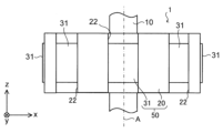
- FIG. 3 is a side view showing the configuration of rotor 1 shown in FIG.
- FIG. 4 is an enlarged plan view showing the configuration of rotor 1 shown in FIG.
- the rotor 1 has a predetermined even number of magnetic poles, 2n (n is a natural number equal to or greater than 1). In Embodiment 1, rotor 1 has eight magnetic poles.
- the rotor 1 has a shaft 10 , ferrite resin magnets 20 as first resin magnets, a plurality of rare earth resin magnets 31 as a plurality of second resin magnets, and a resin portion 40 .
- the number of rare earth resin magnets 31 is the same as the number of poles of rotor 1 . That is, the number of rare earth resin magnets 31 is N, which is an even number.
- the ferrite resin magnet 20 is also called a "ferrite bond magnet”
- the rare earth resin magnet 31 is also called a "rare earth bond magnet”.
- the ferrite resin magnet 20 is supported by the shaft 10 via the resin portion 40 .
- the resin portion 40 is made of, for example, unsaturated polyester resin.
- the resin portion 40 has an inner cylinder portion 41 , an outer cylinder portion 42 , and a plurality of (for example, four) ribs 43 .
- the inner cylindrical portion 41 is cylindrical and fixed to the outer peripheral surface 10 a of the shaft 10 .
- the outer cylindrical portion 42 is cylindrical and fixed to the inner peripheral surface 20 b of the ferrite resin magnet 20 .
- a plurality of ribs 43 connect the inner tubular portion 41 and the outer tubular portion 42 .
- the plurality of ribs 43 radially extend radially outward from the outer peripheral surface of the inner tubular portion 41 .
- a gap V is formed between two ribs 43 adjacent to each other in the circumferential direction C.
- the ferrite resin magnet 20 may be fixed directly to the shaft 10 without the resin portion 40 interposed therebetween.
- the resin portion 40 is also referred to as the "first resin portion 40".
- Ferrite resin magnet 20 includes a ferrite magnet and resin.
- the resin contained in the ferrite resin magnet 20 is, for example, at least one of nylon resin, PPS (Poly Phenylene Sulfide) resin, and epoxy resin.
- FIG. 5 is a plan view showing the structure of the ferrite resin magnet 20 shown in FIG.
- the planar shape of the ferrite resin magnet 20 parallel to the xy plane is annular with the axis A as the center.
- the outer peripheral surface 20c of the ferrite resin magnet 20 as the first outer peripheral surface forms part of the outer peripheral surface 1c of the rotor 1 (see FIG. 4).
- the outer peripheral surface 20c is a radially outward surface of the ferrite resin magnet 20 .
- the ferrite resin magnet 20 has a plurality of grooves 22 provided on the outer peripheral surface 20c.
- a plurality of rare earth resin magnets 31 (see FIG. 4) are arranged in the plurality of grooves 22, respectively.
- the number of the plurality of grooves 22 is the same as the number of the plurality of rare earth resin magnets 31 and the number of poles of the rotor 1 . That is, the number of the plurality of grooves 22 is an even number of N (for example, 8).
- the plurality of grooves 22 are arranged at predetermined intervals in the circumferential direction C. As shown in FIG. In the example shown in FIG. 5, the plurality of grooves 22 are arranged in the circumferential direction C at regular intervals.
- the groove portion 22 is a long groove elongated in the z-axis direction.
- the groove portion 22 has a bottom surface 22a and side surfaces 22b and 22c.
- the bottom surface 22 a is a radially outward surface of the groove portion 22 .
- the side surfaces 22b and 22c extend radially outward from both widthwise ends of the bottom surface 22a. In the example shown in FIG. 5, the side surfaces 22b and 22c extend radially outward so that the width of the groove 22 increases.
- the side surfaces 22b and 22c are boundaries between the ferrite resin magnet 20 and the rare earth resin magnet 31 (hereinafter also referred to as "magnet boundaries").
- the ferrite resin magnet 20 is magnetized so as to have a polar anisotropic orientation. As a result, two grooves 22 adjacent to each other in the circumferential direction C are formed with magnetic poles having different polarities.
- the lines of magnetic force formed between the magnetic poles (that is, the N pole and the S pole) adjacent to each other in the circumferential direction C of the ferrite resin magnet 20 are called magnetic lines of force M.
- a magnetic force line M indicates the direction of the oriented magnetic field formed by the adjacent magnetic poles of the ferrite resin magnet 20 .
- the N-pole groove 22 is denoted as 22n
- the S-pole groove 22 is denoted as 22s.
- the N-pole grooves 22n and the S-pole grooves 22s are alternately arranged.
- the magnetic flux (not shown) that has flowed in from the radially outer side of the S-pole groove 22s advances to the N-pole groove 22n that is adjacent to the groove 22s in the circumferential direction C.
- the rotor 1 (see FIG. 3) does not require a rotor core forming a magnetic path inside the ferrite resin magnet 20 in the radial direction.
- the number of parts in the rotor 1 can be reduced, and the weight of the rotor 1 can be reduced.
- the portion between the N-pole groove portion 22n and the S-pole groove portion 22s adjacent in the circumferential direction C constitutes the interpolar portion 23 of the rotor 1 .
- the rare earth resin magnet 31 constitutes the pole center portion of the rotor 1 .
- the rare earth resin magnet 31 includes a rare earth magnet and resin.
- Rare earth magnets are, for example, neodymium magnets containing neodymium (Nd), iron (Fe) and boron (B), or samarium iron nitrogen magnets containing samarium (Sm), Fe and nitrogen (N).
- the resin contained in the rare earth resin magnet 31 is the same as the resin contained in the ferrite resin magnet 20, for example. That is, the resin contained in the rare earth resin magnet 31 is, for example, at least one of nylon resin, PPS resin and epoxy resin.
- the magnetic pole strength (that is, the amount of magnetism) of the rare earth resin magnet 31 is greater than the magnetic pole strength of the ferrite resin magnet 20 .
- the magnetic force of the rare earth resin magnet 31 is greater than the magnetic force of the ferrite resin magnet 20 .
- the coefficient of linear expansion of the rare earth resin magnet 31 is different from the coefficient of linear expansion of the ferrite resin magnet 20 .
- the rare earth resin magnet 31 is made of a material different from that of the ferrite resin magnet 20 .
- the plurality of rare-earth resin magnets 31 are arranged at intervals in the circumferential direction C.
- the plurality of rare earth resin magnets 31 are arranged in the circumferential direction C at regular intervals.
- the outer peripheral surface 31 c of the rare earth resin magnet 31 as the second outer peripheral surface forms part of the outer peripheral surface 1 c of the rotor 1 .
- Each of the plurality of rare earth resin magnets 31 is magnetized so as to have a polar anisotropic orientation.
- a plurality of rare earth resin magnets 31 adjacent in the circumferential direction C have magnetic poles with different polarities.
- a rotor main body 50 supported by the shaft 10 is configured by the ferrite resin magnet 20 and the plurality of rare earth resin magnets 31 .
- the plurality of rare earth resin magnets 31 are joined to the plurality of grooves 22 of the ferrite resin magnet 20, respectively.
- ferrite resin magnet 20 and rare earth resin magnet 31 are integrally molded (hereinafter also referred to as “two-color molding”) so that rare earth resin magnet 31 is joined to groove 22 of ferrite resin magnet 20 .
- the plurality of rare earth resin magnets 31 are filled in the plurality of grooves 22 respectively.
- integral molding of the ferrite resin magnet 20 and the rare earth resin magnet 31 means that the rare earth resin magnet 31 is molded while the previously manufactured ferrite resin magnet 20 is placed in a mold.
- the plurality of rare earth resin magnets 31 are placed in the mold one by one. No need for placement work. Therefore, productivity of the rotor main body 50 can be improved.
- FIG. 6 is a cross-sectional view of the rotor 1 shown in FIG. 4 taken along line B6-B6.
- the length of the ferrite resin magnet 20 in the z-axis direction (also referred to as the "first length") is L1
- the length of the rare earth resin magnet 31 in the z-axis direction (also referred to as the "second length") is L1.
- L2 is defined as L2.
- Axial length L1 is longer than axial length L2. That is, the relationship between the axial length L1 and the axial length L2 is represented by the following formula (1).
- the ferrite resin magnet 20 constitutes the interpolar portion 23 of the rotor 1 and the rare earth resin magnet 31 constitutes the pole center portion of the rotor 1 . Since the axial length L1 and the axial length L2 satisfy the expression (1), the effective magnetic flux interlinking from the interpolar portion 23 of the rotor 1 to the stator core 61 (hereinafter also referred to as "effective interlinkage magnetic flux") is Since the amount of magnetic flux increases, it is possible to prevent the occurrence of distortion of the effective magnetic flux.
- FIG. 7A is a plan view showing the configuration of a rotor 101a according to Comparative Example 1.
- FIG. 7B is a side view showing the configuration of the rotor 101a according to Comparative Example 1.
- FIG. Rotor 101a differs from rotor 1 according to Embodiment 1 in that the axial length of ferrite resin magnets 120a in the z-axis direction and the axial length of rare earth resin magnets 130a in the z-axis direction are the same.
- FIG. 8(A) is a plan view showing the configuration of a rotor 101b according to Comparative Example 2.
- FIG. FIG. 8B is a side view showing the configuration of a rotor 101b according to Comparative Example 2.
- FIG. in the rotor 101b an annular rare earth resin magnet 130b is arranged on the outer peripheral surface 120c of the annular ferrite resin magnet 120b.
- the rotor 101b differs from the rotor 1 according to the first embodiment and the rotor 101a according to the first comparative example in that the entire outer peripheral surface 101d of the rotor 101b is formed of the rare earth resin magnets 130b. differ.
- Rotor 101b also differs from rotor 1 according to Embodiment 1 in that the axial length of ferrite resin magnet 120b in the z-axis direction and the axial length of rare earth resin magnet 130b in the z-axis direction are the same. .
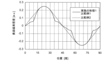
- FIG. 9 is a graph showing the distribution of the surface magnetic flux densities of the rotors 1 and 101a according to the first embodiment and the first comparative example, and the distribution of the surface magnetic flux density of the rotor 101b according to the second comparative example.
- the horizontal axis indicates the position in the circumferential direction C on the outer peripheral surfaces 1c, 101c, and 101d of the rotors 1, 101a, and 101b [unit: degrees]
- the vertical axis indicates the surface magnetic flux density [unit: a. u].
- the solid line graph shows the waveform of the surface magnetic flux density distribution of the rotors 1 and 101a according to the first embodiment and the first comparative example
- the broken line graph shows the waveform of the second comparative example.
- the waveform of the distribution of the surface magnetic flux density of the rotor 101b is shown.
- the waveform of the distribution of the surface magnetic flux density of the rotor 101b according to Comparative Example 2 is a sinusoidal waveform.
- changes in the surface magnetic flux density in the circumferential direction C are uniform.
- the waveforms of the surface magnetic flux density distributions of Embodiment 1 and Comparative Example 1 indicated by the solid line graphs are not gentle compared to the waveforms of the surface magnetic flux density distributions of Comparative Example 2 indicated by the broken line graphs. .
- the change in surface magnetic flux density is not uniform. Specifically, distortion occurs in the portion of the waveform indicated by the solid line graph that corresponds to the interpolar portion of the rotor 1, 101a.
- FIG. 10 shows the distribution of the effective interlinkage magnetic flux of the rotor 1 according to the first embodiment, the distribution of the effective interlinkage magnetic flux of the rotor 101a according to the first comparative example, and the effective interlinkage magnetic flux of the rotor 101b according to the second comparative example.
- the horizontal axis indicates the positions in the circumferential direction C on the outer peripheral surfaces 1c, 101c, and 101d of the rotors 1, 101a, and 101b [unit: degrees]
- the vertical axis indicates the effective interlinkage magnetic flux [unit: Wb ] is shown.
- the solid line indicates the waveform W21 of the effective interlinkage magnetic flux distribution of the rotor 1 according to the first embodiment.
- the dashed line indicates the waveform W22 of the effective interlinkage magnetic flux distribution of the rotor 101a according to Comparative Example 1
- the dashed line indicates the waveform W23 of the effective interlinkage magnetic flux distribution of the rotor 101b according to Comparative Example 2.
- a waveform W23 is a sinusoidal waveform.
- changes in the surface magnetic flux density in the circumferential direction C are uniform.
- the waveform W22 is less smooth than the waveform W23.
- the change in surface magnetic flux density is not uniform in the rotor 101b.
- distortion occurs in the inter-electrode portion 23 of the rotor 1 in the waveform W22.
- the distribution of the surface magnetic flux density is represented by the waveform W22, there is a problem that distortion occurs in the effective interlinking magnetic flux interlinking with the stator core 61 (see FIG. 3).
- the waveform W21 has a shape more similar to a sine wave than the waveform W22.
- the axial length L1 of the ferrite resin magnet 20 is longer than the axial length L2 of the rare earth resin magnet 31 in the first embodiment.
- the amount of effective interlinkage magnetic flux flowing from the ferrite resin magnet 20 forming the interpolar portion 23 (see FIG. 5) of the rotor 1 to the stator core 61 (see FIG. 3) increases. Therefore, it is possible to suppress the occurrence of distortion of the effective interlinkage magnetic flux interlinking with the stator core 61 in the interpolar portion 23 of the rotor 1 . Therefore, the distortion of the induced voltage and the generation of cogging torque, which cause vibration and noise in the electric motor 100, are suppressed.
- the product of the axial length L1 and the magnetic force Br1 is , greater than the product of the axial length L2 and the magnetic force Br2.
- the relationship between the axial length L1, the magnetic force Br1, the axial length L2, and the magnetic force Br2 is represented by the following equation (2). L1 ⁇ Br1>L2 ⁇ Br2 (2)
- the axial length L1 of the ferrite resin magnet 20 is proportional to the ratio Br2/Br1 of the magnetic force Br2 of the rare earth resin magnet 31 to the magnetic force Br1 of the ferrite resin magnet 20.
- FIG. Therefore, by lengthening the axial length L1 of the ferrite resin magnet 20 according to the ratio Br2/Br1, the amount of effective magnetic flux interlinking from the interpolar portion 23 of the rotor 1 to the stator core 61 can be increased. can be done. Therefore, it is possible to further suppress the occurrence of distortion of the effective magnetic flux in the interpolar portion 23 of the rotor 1 .
- the outer peripheral surface 1 c of the rotor 1 is formed by the outer peripheral surface 20 c of the ferrite resin magnet 20 and the outer peripheral surfaces 31 c of the plurality of rare earth resin magnets 31 .
- the amount of rare earth resin magnets 31 used can be reduced compared to the rotor 101b.
- the amount of rare earth resin magnets 31 used can be reduced by about 20% compared to rotor 101b.
- the rare earth resin magnet 31 is more expensive than the ferrite resin magnet 20.
- the material unit price of the rare earth resin magnet 31 is ten times or more the material unit price of the ferrite resin magnet 20 . Therefore, the outer peripheral surface 1c of the rotor 1 is composed of the outer peripheral surface 20c of the ferrite resin magnet 20 and the outer peripheral surfaces 31c of the plurality of rare earth resin magnets 31, so that the usage amount of the rare earth resin magnets 31 can be reduced. and the cost of the rotor 1 can be reduced.
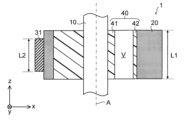
- FIG. 11 is a partial cross-sectional view showing the configuration of rotor 1 and stator 6 according to the first embodiment.
- the axial length L1 of the ferrite resin magnet 20 is longer than the axial length L3 of the stator core 61 when the axial length of the stator core 61 is L3.
- the effective magnetic flux interlinking from the ferrite resin magnet 20 to the stator core 61 can be increased.
- the ferrite resin magnet 20 increases the amount of effective magnetic flux interlinking with the stator core 61 from the portion (hereinafter also referred to as “overhang portion”) 24 that does not face the stator core 61 in the radial direction.
- the axial length L1 of the ferrite resin magnet 20 is too large relative to the axial length L3 of the stator core 61, the amount of the ferrite resin magnet 20 used increases. Further, as a result of the inventor's intensive research, if the axial length L1 of the ferrite resin magnet 20 becomes too long with respect to the axial length L3 of the stator core 61, that is, if the length of the overhang portion 24 becomes too long, the stator core It was found that the rate of increase in the amount of magnetic flux interlinking with 61 is reduced.
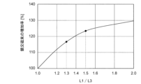
- FIG. 12 is a graph showing the relationship between the ratio L1/L3 and the increase rate of the interlinkage magnetic flux.
- the horizontal axis indicates the ratio L1/L3
- the vertical axis indicates the rate of increase [unit: %] of the interlinking magnetic flux interlinking from the ferrite resin magnet 20 to the stator core 61 .
- the ratio L1/L3 is 1.5 or more, the increase rate of the interlinkage magnetic flux is lower than when the ratio L1/L3 is less than 1.5. rice field. Therefore, the ratio L1/L3 is preferably less than 1.5.
- the relationship between the axial length L1 of the ferrite resin magnet 20 and the axial length L3 of the stator core 61 preferably satisfies the following formula (4).
- the amount of interlinkage magnetic flux can be increased while suppressing the amount of ferrite resin magnet 20 used.
- the ratio L1/L3 is more preferably less than 1.3. That is, the relationship between the axial length L1 of the ferrite resin magnet 20 and the axial length L3 of the stator core 61 preferably satisfies the following formula (5). As a result, it is possible to further increase the amount of interlinkage magnetic flux while further suppressing the amount of ferrite resin magnet 20 used. L1 ⁇ 1.3 ⁇ L3 (5)
- FIG. 13 is a flow chart showing the manufacturing process of the rotor 1. As shown in FIG. In the manufacturing process of the rotor 1, a first mold for molding the ferrite resin magnets 20, a second mold for molding the rare earth resin magnets 31, magnets for orientation, and a magnetizer are used.
- step ST1 the inside of the first mold for molding the ferrite resin magnet 20 is filled with the raw material of the ferrite resin magnet 20.
- the ferrite resin magnet 20 is molded by injection molding, for example.
- the ferrite resin magnet 20 may be molded by other molding methods such as press molding instead of injection molding.
- step ST2 while orienting the ferrite resin magnet 20, the ferrite resin magnet 20 having a predetermined shape is molded.
- a magnet for orientation is used to orient the raw material of the ferrite resin magnet 20 while generating a magnetic field having polar anisotropy inside the first mold. Mold 20. As a result, the ferrite resin magnet 20 having polar anisotropy is molded.
- step ST3 the molded ferrite resin magnet 20 is cooled.
- step ST4 the ferrite resin magnet 20 is taken out from the first mold.
- step ST5 the ferrite resin magnet 20 taken out is demagnetized.
- step ST6 the ferrite resin magnet 20 is placed inside the second mold for injection molding the rare earth resin magnet 31.
- step ST7 the raw material of the rare earth resin magnet 31 is filled into the grooves 22 of the ferrite resin magnet 20 placed in the second mold.
- the rare earth resin magnet 31 is molded by injection molding, for example.
- the rare earth resin magnet 31 may be molded by other molding methods such as press molding instead of injection molding.
- step ST8 while orienting the raw material of the rare earth resin magnet 31, the rare earth resin magnet 31 having a predetermined shape is molded.
- step ST8 for example, a magnet for orientation is used to orient the raw material of the rare earth resin magnet 31 while generating a magnetic field having polar anisotropy inside the second mold. 31 is molded. Thereby, the rotor main body 50 in which the ferrite resin magnet 20 and the plurality of rare earth resin magnets 31 are integrally formed is formed.
- step ST9 the rotor main body 50 formed in step ST8 is cooled.
- step ST10 the cooled rotor main body 50 is taken out from the second mold.
- step ST11 the rotor main body 50 taken out in step ST10 is demagnetized.
- step ST12 the rotor main body 50 is connected to the shaft 10.
- the rotor main body 50 is connected to the shaft 10 by integrating the rotor main body 50 and the shaft 10 via the resin portion 40 .
- step ST13 for example, the rotor main body 50 is magnetized using a magnetizer.
- the rotor 1 includes the ferrite resin magnet 20 and the plurality of rare earth resin magnets 31 arranged in the plurality of grooves 22 provided on the outer peripheral surface 20c of the ferrite resin magnet 20.
- the outer peripheral surface 1 c of the rotor 1 is composed of the outer peripheral surface 20 c of the ferrite resin magnet 20 and the outer peripheral surfaces 31 c of the plurality of rare earth resin magnets 31 . Therefore, compared to the rotor 101b according to Comparative Example 2 in which the entire outer peripheral surface 101d of the rotor 101b is composed of the rare earth resin magnets 131b, the amount of the rare earth resin magnets 31 used is reduced. Therefore, the cost of the rotor 1 can be reduced compared to the cost of the rotor 101b according to the second comparative example.
- the axial length L1 of the ferrite resin magnet 20 is longer than the axial length L2 of the rare earth resin magnet 31.
- the amount of interlinkage magnetic flux linking the stator core 61 from the ferrite resin magnet 20 forming the interpolar portion 23 of the rotor 1 increases. Therefore, since the waveform W1 of the distribution of the surface magnetic flux density of the rotor 1 approaches the sinusoidal waveform W3, the occurrence of distortion of the effective magnetic flux in the interpolar portion 23 can be suppressed.
- the axial length L1 of the ferrite resin magnet 20 satisfies the above-described formula (3).
- the axial length L1 of the ferrite resin magnet 20 can be lengthened according to the ratio Br2/Br1 of the magnetic force Br2 of the rare earth resin magnet 31 to the magnetic force Br1 of the ferrite resin magnet 20.
- the amount of interlinkage magnetic flux linking from the interpolar portion 23 of the rotor 1 to the stator core 61 can be further increased. Therefore, the occurrence of distortion of the effective magnetic flux in the interpolar portion 23 can be further suppressed.
- the axial length L1 of the ferrite resin magnet 20 is less than 1.5 times the axial length L3 of the stator core 61. If the axial length L1 of the ferrite resin magnet 20 is made longer than the axial length L3 of the stator core 61, the magnetic flux of the overhang portion, which is the portion of the ferrite resin magnet 20 that does not face the stator core 61 in the radial direction, , are linked to the stator core 61 . Therefore, the magnetic flux amount of the interlinkage magnetic flux can be increased.
- the increase rate of the interlinkage magnetic flux interlinking from the ferrite resin magnet 20 to the stator core 61 decreases when the axial length L1 exceeds 1.5 times the axial length L3. ,found. Therefore, since the axial length L1 is less than 1.5 times the axial length L3, the amount of the ferrite resin magnet 20 used is suppressed, and the amount of interlinkage magnetic flux is increased, thereby suppressing the occurrence of distortion of the effective magnetic flux. can.
- the axial length L1 of the ferrite resin magnet 20 is less than 1.3 times the axial length L3 of the stator core 61. As a result, it is possible to further increase the amount of interlinkage magnetic flux while further suppressing the amount of ferrite resin magnets 20 used in the rotor 1 .
- electric motor 100 has rotor 1 and stator 6 .
- the rotor 1 can suppress the occurrence of distortion of the effective magnetic flux. Therefore, by including the rotor 1 in the electric motor 100 , it is possible to suppress a decrease in the output of the electric motor 100 . In addition, since distortion of the induced voltage and cogging torque are less likely to occur, vibration and noise in the electric motor 100 can be reduced.
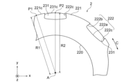
- FIG. 14 is a plan view showing part of the configuration of the rotor 2 according to the second embodiment. 14, the same or corresponding components as those shown in FIG. 4 are given the same reference numerals as those shown in FIG.
- a rotor 2 according to the second embodiment differs from the rotor 1 according to the first embodiment in terms of the shapes of ferrite resin magnets 220 and rare earth resin magnets 231 . Except for this point, the rotor 2 according to the second embodiment is the same as the rotor 1 according to the first embodiment. 1 and 3 are therefore referred to in the following description.
- the rotor 2 has a shaft 10 (see FIG. 3), ferrite resin magnets 220, and rare earth resin magnets 231.
- the ferrite resin magnet 220 has a cylindrical magnet main body 221 and a plurality of grooves 222 .
- the magnet body portion 221 is a portion of the ferrite resin magnet 220 that is supported by the shaft 10 .
- a plurality of grooves 222 are formed on the outer peripheral surface 221c of the magnet main body 221 .
- the outer peripheral surface 221c is a radially outward surface of the ferrite resin magnet 220 .
- the first distance between the axis A and the point P1 on the outer peripheral surface 221c of the magnet main body 221 is the distance R1
- the distance between the axis A and the point P2 on the outer peripheral surface 231c of the rare earth resin magnet 231 is Let the second distance be distance R2.
- Distance R1 is the maximum distance between outer peripheral surface 221c of ferrite resin magnet 220 and axis A
- distance R2 is the maximum distance between outer peripheral surface 231c of rare earth resin magnet 231 and axis A.
- distance R1 is longer than distance R2. That is, the relationship between the distance R1 and the distance R2 is represented by the following formula (6).
- the air gap G (see FIG. 1) between the outer peripheral surface 221c of the ferrite resin magnet 220 and the stator core 61 (see FIG. 1) can be narrowed. can. As a result, the amount of effective magnetic flux interlinking with the stator core 61 increases. Therefore, the distortion of the effective magnetic flux in the interpolar portion of the rotor 2 can be reduced.
- the groove portion 222 of the ferrite resin magnet 220 has a bottom surface 222a, a first side surface 222b, and a second side surface 222c.
- the first side surface 222b and the second side surface 222c extend radially outward from both widthwise ends of the bottom surface 22a.
- the first side surface 222b and the second side surface 222c extend radially outward from both widthwise ends of the bottom surface 222a so that the width of the groove 222 is narrowed.
- the rare earth resin magnets 231 arranged in the grooves 222 can be prevented from coming off due to interface peeling due to expansion or contraction due to temperature change or centrifugal force acting on the rotor 2 .
- the distance R1 between the point P1 on the outer peripheral surface 221c of the ferrite resin magnet 220 and the axis A of the shaft 10 is the point P2 on the outer peripheral surface 231c of the rare earth resin magnet 231. is longer than the distance R2 between and the axis A.
- the air gap G between the ferrite resin magnet 220 and the stator 6 is narrowed, so that the amount of effective magnetic flux interlinking with the stator core 61 is increased. Therefore, the distortion of the effective magnetic flux in the interpolar portion of the rotor 2 can be reduced.
- the first side surface 222b and the second side surface 222c of the groove portion extend radially outward from both ends in the width direction of the bottom surface 222a so that the width of the groove portion 222 is narrowed.
- the rare earth resin magnet 231 can be prevented from coming off due to interface peeling due to expansion or contraction due to temperature change or centrifugal force acting on the rotor 2 .
- FIG. 16 is a cross-sectional view of the rotor 3 shown in FIG. 15 taken along line B16-B16.
- FIG. 17 is a cross-sectional view of the rotor 3 shown in FIG. 15 taken along line B17-B17.
- components that are the same as or correspond to those shown in FIGS. 3 and 4 are labeled with the same reference numerals as those shown in FIGS.
- the rotor 3 according to the third embodiment differs from the rotor 1 according to the first embodiment in terms of the shape of the ferrite resin magnets 320 and the shape of the rare earth resin magnets 331 . Except for this point, the rotor 3 according to the third embodiment is the same as the rotor 1 according to the first embodiment.
- the rotor 3 has a shaft 10, ferrite resin magnets 320, and a plurality of rare earth resin magnets 331.
- the ferrite resin magnet 320 has a plurality of grooves 322 provided on the outer peripheral surface 320c.
- a plurality of rare earth resin magnets 331 are arranged in the plurality of grooves 322 .
- Each groove 322 of the plurality of grooves 322 has a first portion 322a in which the rare earth resin magnet 331 is arranged, and a second portion 322b arranged closer to the end surface 320e in the z-axis direction than the first portion 322a. .
- the rare earth resin magnet 331 has a column portion 71, a first overhanging portion 72, and a second overhanging portion 73.
- the columnar portion 71 extends in the z-axis direction.
- Column portion 71 is arranged in groove portion 322 of ferrite resin magnet 320 .
- the column portion 71 is arranged in the first portion 322 a of the groove portion 322 .
- the shape of the columnar portion 71 when viewed in the z-axis direction is, for example, a fan shape.
- the inner peripheral surface and the outer peripheral surface of the column portion 71 are formed concentrically.
- the thickness of the pillar portion 71 in the xy plane is constant in the circumferential direction C. As shown in FIG.
- FIG. 18 is a cross-sectional view of the rotor 3 shown in FIG. 17 taken along line B18-B18.
- the first projecting portion 72 extends radially inward from the +z-axis side end portion 71 a of the column portion 71 .
- the second projecting portion 73 extends radially inward from the ⁇ z-axis side end portion 71b of the column portion 71 .
- the width in the circumferential direction C of each of the first overhanging portion 72 and the second overhanging portion 73 narrows radially inward.
- the rare earth resin magnet 331 includes the first protruding portion 72 extending radially inward from the +z-axis side end 71a of the column portion 71 and the -z-axis of the column portion 71. and a second projecting portion 73 extending radially inward from the side end portion 71b. Therefore, in FIG.
- the distance (third distance) connecting the central portion of the outer peripheral surface 320c of the ferrite resin magnet 320 in the z-axis direction and the axis A is R3, and the end portion of the outer peripheral surface 320c in the z-axis direction and the axis A
- the distance R3 is longer than the distance R4. That is, the relationship between the distance R3 and the distance R4 is represented by Equation (7) below.
- the distance R3 being longer than the distance R4 means that in the ferrite resin magnet 320, the depth of the second portion 322b of the groove portion 322 is greater than the depth of the first portion 322a of the groove portion 322.
- the rare earth magnets are affected by expansion or contraction due to temperature changes or by centrifugal force acting on the rotor 1.
- a radially inward surface of the resin magnet 31 that is in contact with the ferrite resin magnet 20 (hereinafter also referred to as “interface”) may fall out of the groove 22 of the ferrite resin magnet 20 .
- the distance R3 connecting the center portion of the outer peripheral surface 320c of the ferrite resin magnet 320 in the z-axis direction and the axis A is the distance connecting the end portion of the outer peripheral surface 320c in the z-axis direction and the axis A. Longer than R4.
- the first projecting portion 72 and the second projecting portion 73 shown in FIGS. 17 and 18 can be formed on the rare earth resin magnet 331 .
- the joint area between the rare earth resin magnet 331 and the ferrite resin magnet 320 increases at the end of the rare earth resin magnet 331 in the z-axis direction.
- the interface of the rare earth resin magnet 331 is less likely to separate due to expansion or contraction due to temperature change or centrifugal force acting on the rotor 3 . Therefore, the rare earth resin magnet 331 is less likely to drop out of the groove 322 of the ferrite resin magnet 320 .
- each of the first projecting portion 72 and the second projecting portion 73 when viewed in the z-axis direction is, for example, a substantially triangular shape.
- the shape of the first projecting portion 72 and the shape of the second projecting portion 73 are not limited to substantially triangular, and may be other shapes.
- the rare earth resin magnet 331 may have only one of the first projecting portion 72 and the second projecting portion 73 .
- the distance R3 between the central portion in the z-axis direction of the outer peripheral surface 320c of the ferrite resin magnet 320 and the axis A is longer than the distance R4 to A.
- the first projecting portion 72 and the second projecting portion 73 shown in FIGS. 17 and 18 can be formed on the rare earth resin magnet 331 . Therefore, since the joint area between the rare earth resin magnet 331 and the ferrite resin magnet 320 increases, expansion or contraction due to temperature change or centrifugal force acting on the rotor 3 causes the rare earth resin magnet 331 to move from the groove 322 of the ferrite resin magnet 320. You can prevent it from falling off. Therefore, it is possible to provide the rotor 3 with high reliability against temperature change and centrifugal force.
- FIG. 19 is a plan view showing the configuration of the rotor 4 according to Embodiment 4.
- FIG. FIG. 20 is a cross-sectional view of the rotor 4 shown in FIG. 19 taken along line B20-B20. 19 and 20, the same or corresponding components as those shown in FIGS. 3 and 4 are labeled with the same reference numerals as those shown in FIGS.
- Rotor 4 according to the fourth embodiment differs from rotor 1 according to the first embodiment in the shape of ferrite resin magnets 420 . Except for this point, the rotor 4 according to the fourth embodiment is the same as the rotor 1 according to the first embodiment. Therefore, FIG. 5 will be referred to in the following description.
- the rotor 4 has a shaft 10, ferrite resin magnets 420, a plurality of rare earth resin magnets 31, and a resin portion 406.
- the distance (fifth distance) between the central portion 420g in the z-axis direction on the inner peripheral surface 420b of the ferrite resin magnet 420 and the axis A is R5
- the end portion 420h in the z-axis direction on the inner peripheral surface 420b and the axis A (sixth distance) is R6.
- distance R5 is longer than distance R6. That is, the distance R5 and the distance R6 are represented by the following formula (8). R5>R6 (8)
- the radial width of the ferrite resin magnet 120a of the comparative example shown in FIGS. It must have the thickness necessary to When the axial length of the ferrite resin magnet 420 is longer than the axial length of the rare earth resin magnet 31, the portion of the ferrite resin magnet 420 that is not in contact with the rare earth resin magnet 31 (that is, the end portion in the z-axis direction) has the rare earth resin magnet No need to support 31. Therefore, of the ends of the ferrite resin magnet 420 in the z-axis direction, the portion forming the interpolar portion 23 (see FIG. 5) of the rotor 4 has the minimum width w for forming the magnetic path.
- the usage amount of the ferrite resin magnet 420 can be suppressed.
- the width w is the value obtained by subtracting the distance R5 from the distance R0.
- the distance R5 between the central portion 420g in the z-axis direction of the inner peripheral surface 420b of the ferrite resin magnet 420 and the axis A is equal to the end of the inner peripheral surface 420b in the z-axis direction.
- the portion of the ferrite resin magnet 420 not in contact with the rare earth resin magnet 31 (that is, the end portion in the z-axis direction) has a rare earth Since it is not necessary to support the resin magnet 31, it is sufficient that the interpolar portion 23 (see FIG. 5) has a thickness w for forming a magnetic path. Thereby, the usage amount of the ferrite resin magnet 420 can be suppressed.
- FIG. 21 is a plan view showing the configuration of the rotor 5 according to Embodiment 5.
- FIG. FIG. 22 is a cross-sectional view of the rotor 5 shown in FIG. 21 taken along line B22-B22. 21 and 22, components identical or corresponding to those shown in FIGS. 4 and 6 are labeled with the same reference numerals as those shown in FIGS.
- a rotor 5 according to Embodiment 5 is different from rotors 1 to 4 according to any one of Embodiments 1 to 4 in that second resin portions 81 and 82 are further provided. Except for this point, the rotor 5 according to the fifth embodiment is the same as the rotors 1 to 4 according to any one of the first to fourth embodiments.
- the rotor 5 includes a shaft 10, a ferrite resin magnet 20, a plurality of rare earth resin magnets 31, a first resin portion 40, and second resin portions 81 and 82.
- Each of the second resin portions 81 and 82 is an annular member centered on the axis A.
- the second resin portions 81 and 82 are made of a resin material such as unsaturated polyester resin, for example.
- the second resin parts 81 and 82 are fixed to the ferrite resin magnet 20 and the rare earth resin magnet 31.
- the second resin portions 81 and 82 cover the ends of the ferrite resin magnet 20 and the rare earth resin magnet 31 in the z-axis direction, respectively.
- the second resin portion 81 is fixed to the end face 20e of the ferrite resin magnet 20 facing the +z-axis direction and the end face 31e of the rare earth resin magnet 31 facing the +z-axis direction.
- the second resin portion 82 is fixed to the end face 20f of the ferrite resin magnet 20 facing the -z-axis direction and the end face 31f of the rare earth resin magnet 31 facing the -z-axis direction.
- the second resin parts 81 and 82 are connected to the ends of the ferrite resin magnet 20 and the rare earth resin magnet 31 in the z-axis direction, respectively.
- the rare earth resin magnet 31 is connected to the ferrite resin magnet 20 via the second resin portions 81 and 82 . Therefore, it is possible to further prevent the rare earth resin magnet 31 from coming off due to the centrifugal force acting during rotation. In addition, it is possible to further prevent the rare earth resin magnet 31 from peeling off due to temperature changes.
- the rotor 5 may have at least one of the plurality of second resin portions 81 and 82 .
- the rotor 5 further includes the second resin parts 81 and 82 connected to the ends of the ferrite resin magnet 20 and the rare earth resin magnet 31 in the z-axis direction, respectively. .
- the rare earth resin magnet 31 is connected to the ferrite resin magnet 20 via the second resin portions 81 and 82 . Therefore, it is possible to further prevent the rare earth resin magnet 31 from coming off due to the centrifugal force acting during rotation. In addition, it is possible to further prevent the rare earth resin magnet 31 from peeling off due to temperature changes. Therefore, a highly reliable rotor 5 can be provided.
- FIG. 23 is a plan view showing the configuration of a rotor 5A according to a modification of the fifth embodiment.
- FIG. 24 is a cross-sectional view of the rotor 5A shown in FIG. 23 taken along line B24-B24.
- a rotor 5A according to a modification of the fifth embodiment differs from the rotor 5 according to the fifth embodiment in that the second resin portions 81A and 82A are integrated with the first resin portion 540. . Except for this point, the rotor 5A according to the modification of the fifth embodiment is the same as the rotor 5 according to the fifth embodiment.
- the rotor 5A includes a shaft 10, a ferrite resin magnet 20, a plurality of rare earth resin magnets 31, a first resin portion 540, and second resin portions 81A and 82A.
- the resin portion 540 has an inner cylinder portion 41 and a plurality of ribs 43 connecting the inner cylinder portion 41 and the second resin portions 81A and 82A.
- the second resin portions 81A and 82A are connected to the ends of the ferrite resin magnet 20 and the rare earth resin magnet 31 in the z-axis direction, respectively.
- the second resin portions 81A and 82A are formed integrally with the resin portion 540.
- the second resin portions 81A and 82A are connected to the resin portion 540.
- shaft 10, ferrite resin magnet 20 and rare earth resin magnet 31 are connected via first resin portion 540 and second resin portions 81A and 82A.
- the strength of the second resin portions 81A and 82A is increased, so that the rare earth resin magnet 31 can be further prevented from coming off.
- the second resin portions 81A and 82A can also be molded at the same time. Therefore, the manufacturing process of the rotor 5A can be simplified.
- the second resin portions 81A and 82A are integrally formed with the first resin portion 540. As shown in FIG. As a result, the strength of the second resin portions 81A and 82A is increased, so that the dropout of the rare earth resin magnet 31 can be further prevented. Therefore, a highly reliable rotor 5A can be provided. Further, when the shaft 10 and the ferrite resin magnet 20 are integrally molded with the resin portion 540 interposed therebetween, the second resin portions 81A and 82A can also be molded at the same time. Therefore, the manufacturing process of the rotor 5A can be simplified.
- FIG. 25 schematically shows the configuration of blower 600 according to the sixth embodiment.
- blower 600 has electric motor 100 and fan 601 as an impeller driven by electric motor 100 .
- the fan 601 is attached to the shaft 10 of the electric motor 100 (see FIG. 1, for example).
- the fan 601 rotates to generate an airflow.
- the blower 600 is used, for example, as an outdoor blower for an outdoor unit 720 of an air conditioner 700 shown in FIG. 26, which will be described later.
- fan 601 is, for example, a propeller fan.
- blower 600 has electric motor 100 according to the first embodiment. As described above, since electric motor 100 suppresses a decrease in output, blower 600 can also suppress a decrease in output. In addition, since the vibration and noise of electric motor 100 are reduced, the vibration and noise of fan 600 can be reduced.
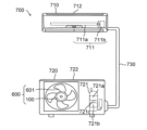
- FIG. 26 is a diagram schematically showing the configuration of an air conditioner 700 according to Embodiment 7. As shown in FIG.
- the air conditioner 700 has an indoor unit 710, an outdoor unit 720, and refrigerant pipes 730.
- the indoor unit 710 and the outdoor unit 720 are connected by a refrigerant pipe 730 to form a refrigerant circuit in which refrigerant circulates.
- the air conditioner 700 can operate, for example, in a cooling operation in which cold air is blown from the indoor unit 710 or in a heating operation in which warm air is blown.
- the indoor unit 710 has an indoor fan 711 and a housing 712 that accommodates the indoor fan 711 .
- the indoor fan 711 has an electric motor 711a and a fan 711b driven by the electric motor 711a.
- the fan 711b is attached to the shaft of the electric motor 711a. Rotation of the shaft of the electric motor 711a rotates the fan 711b to generate airflow.
- Fan 711b is, for example, a cross-flow fan.
- the outdoor unit 720 has a fan 600 as an outdoor fan, a compressor 721, and a housing 722 that accommodates the fan 600 and the compressor 721.
- the compressor 721 has a compression mechanism portion 721a that compresses refrigerant and an electric motor 721b that drives the compression mechanism portion 721a.
- the compression mechanism portion 721a and the electric motor 721b are connected to each other by a shaft 721c. Note that the electric motor 100 according to the first embodiment may be used as the electric motor 721b of the compressor 721.
- the outdoor unit 720 further has a four-way valve (not shown) that switches the flow direction of the refrigerant.
- the four-way valve of the outdoor unit 720 allows the high-temperature, high-pressure refrigerant gas delivered from the compressor 721 to flow through the heat exchanger of the outdoor unit 720 during cooling operation, and through the heat exchanger of the indoor unit 710 during heating operation.
- the fan 600 according to Embodiment 6 may be used not only as the outdoor fan of the outdoor unit 720 but also as the indoor fan 711 described above.
- electric motor 100 according to Embodiment 1 may be provided not only in air conditioner 700 but also in other electrical equipment.
- the outdoor unit 720 of the air conditioner 700 has the electric motor 100 according to the first embodiment. As described above, in the electric motor 100, a decrease in output is suppressed, so in the air conditioner 700 as well, a decrease in output can be suppressed. In addition, since the vibration and noise in the electric motor 100 are reduced, the noise reduction of the air conditioner 700 can be realized.
Landscapes
- Engineering & Computer Science (AREA)
- Power Engineering (AREA)
- Manufacturing & Machinery (AREA)
- Permanent Field Magnets Of Synchronous Machinery (AREA)
Priority Applications (4)
| Application Number | Priority Date | Filing Date | Title |
|---|---|---|---|
| US18/716,279 US20250038594A1 (en) | 2022-01-26 | 2022-01-26 | Rotor, electric motor, blower, and air conditioner |
| PCT/JP2022/002861 WO2023144919A1 (ja) | 2022-01-26 | 2022-01-26 | 回転子、電動機、送風機及び空気調和装置 |
| JP2023576447A JPWO2023144919A1 (https=) | 2022-01-26 | 2022-01-26 | |
| CN202280089346.6A CN118591965A (zh) | 2022-01-26 | 2022-01-26 | 转子、电动机、送风机以及空调装置 |
Applications Claiming Priority (1)
| Application Number | Priority Date | Filing Date | Title |
|---|---|---|---|
| PCT/JP2022/002861 WO2023144919A1 (ja) | 2022-01-26 | 2022-01-26 | 回転子、電動機、送風機及び空気調和装置 |
Publications (1)
| Publication Number | Publication Date |
|---|---|
| WO2023144919A1 true WO2023144919A1 (ja) | 2023-08-03 |
Family
ID=87471182
Family Applications (1)
| Application Number | Title | Priority Date | Filing Date |
|---|---|---|---|
| PCT/JP2022/002861 Ceased WO2023144919A1 (ja) | 2022-01-26 | 2022-01-26 | 回転子、電動機、送風機及び空気調和装置 |
Country Status (4)
| Country | Link |
|---|---|
| US (1) | US20250038594A1 (https=) |
| JP (1) | JPWO2023144919A1 (https=) |
| CN (1) | CN118591965A (https=) |
| WO (1) | WO2023144919A1 (https=) |
Citations (6)
| Publication number | Priority date | Publication date | Assignee | Title |
|---|---|---|---|---|
| JP2005151757A (ja) | 2003-11-19 | 2005-06-09 | Mate Co Ltd | ローター及びローターの製造方法 |
| JP2007208104A (ja) | 2006-02-03 | 2007-08-16 | Matsushita Electric Ind Co Ltd | 複合ボンド磁石成形体 |
| JP2011087393A (ja) | 2009-10-14 | 2011-04-28 | Mitsubishi Electric Corp | 同期電動機の回転子 |
| JP2016219607A (ja) * | 2015-05-21 | 2016-12-22 | 中川電化産業株式会社 | 磁石およびマグネットロータ |
| JP2018074765A (ja) * | 2016-10-31 | 2018-05-10 | パナソニックIpマネジメント株式会社 | 電動機 |
| WO2021192236A1 (ja) * | 2020-03-27 | 2021-09-30 | 三菱電機株式会社 | 回転子、電動機、送風機、空気調和装置、及び回転子の製造方法 |
-
2022
- 2022-01-26 CN CN202280089346.6A patent/CN118591965A/zh active Pending
- 2022-01-26 JP JP2023576447A patent/JPWO2023144919A1/ja not_active Ceased
- 2022-01-26 WO PCT/JP2022/002861 patent/WO2023144919A1/ja not_active Ceased
- 2022-01-26 US US18/716,279 patent/US20250038594A1/en active Pending
Patent Citations (6)
| Publication number | Priority date | Publication date | Assignee | Title |
|---|---|---|---|---|
| JP2005151757A (ja) | 2003-11-19 | 2005-06-09 | Mate Co Ltd | ローター及びローターの製造方法 |
| JP2007208104A (ja) | 2006-02-03 | 2007-08-16 | Matsushita Electric Ind Co Ltd | 複合ボンド磁石成形体 |
| JP2011087393A (ja) | 2009-10-14 | 2011-04-28 | Mitsubishi Electric Corp | 同期電動機の回転子 |
| JP2016219607A (ja) * | 2015-05-21 | 2016-12-22 | 中川電化産業株式会社 | 磁石およびマグネットロータ |
| JP2018074765A (ja) * | 2016-10-31 | 2018-05-10 | パナソニックIpマネジメント株式会社 | 電動機 |
| WO2021192236A1 (ja) * | 2020-03-27 | 2021-09-30 | 三菱電機株式会社 | 回転子、電動機、送風機、空気調和装置、及び回転子の製造方法 |
Also Published As
| Publication number | Publication date |
|---|---|
| US20250038594A1 (en) | 2025-01-30 |
| CN118591965A (zh) | 2024-09-03 |
| JPWO2023144919A1 (https=) | 2023-08-03 |
Similar Documents
| Publication | Publication Date | Title |
|---|---|---|
| US20110241467A1 (en) | Permanent magnet motor | |
| US11101709B2 (en) | Electric motor, air blower, and air conditioner | |
| JP7072726B2 (ja) | 回転子、電動機、送風機、空気調和機、及び回転子の製造方法 | |
| US11888368B2 (en) | Rotor, electric motor, air blower, air conditioner, and method for fabricating rotor | |
| WO2018029818A1 (ja) | 電動機、圧縮機、冷凍空調装置および電動機の製造方法 | |
| CN111106685A (zh) | 基于磁极异形阵列的永磁电机 | |
| US20250211043A1 (en) | Motor, blower, and air conditioner | |
| JP7442688B2 (ja) | 回転子、電動機、送風機及び空気調和装置 | |
| CN115088163A (zh) | 送风机及空气调节装置 | |
| WO2023144919A1 (ja) | 回転子、電動機、送風機及び空気調和装置 | |
| WO2023042366A1 (ja) | 回転子、電動機、送風機、空気調和装置、及び回転子の製造方法 | |
| JP7098047B2 (ja) | モータ、ファン、および空気調和機 | |
| JP7415024B2 (ja) | 電動機、送風機及び空気調和装置 | |
| JP7531692B2 (ja) | 回転子、電動機、送風機及び空気調和装置 | |
| WO2022210434A1 (ja) | モータ、送風装置、および冷凍装置 | |
| US20230039239A1 (en) | Consequent pole rotor, motor, fan, and air conditioner | |
| JP7403685B2 (ja) | 回転子、電動機、送風機、空気調和装置、及び回転子の製造方法 | |
| CN104662778A (zh) | 径向间隙型旋转电机、送风机、压缩机和空调机 | |
| WO2025088786A1 (ja) | モータ、送風機および空気調和装置 | |
| JP2023144928A (ja) | モータ、圧縮装置、送風装置、および冷凍装置 | |
| WO2024100869A1 (ja) | 回転子、電動機、ファン、及び空気調和機 | |
| JP2022152164A (ja) | モータ、送風装置、および冷凍装置 | |
| JP2005192264A (ja) | 電動機 |
Legal Events
| Date | Code | Title | Description |
|---|---|---|---|
| 121 | Ep: the epo has been informed by wipo that ep was designated in this application |
Ref document number: 22923787 Country of ref document: EP Kind code of ref document: A1 |
|
| WWE | Wipo information: entry into national phase |
Ref document number: 2023576447 Country of ref document: JP |
|
| WWE | Wipo information: entry into national phase |
Ref document number: 18716279 Country of ref document: US |
|
| WWE | Wipo information: entry into national phase |
Ref document number: 202280089346.6 Country of ref document: CN |
|
| NENP | Non-entry into the national phase |
Ref country code: DE |
|
| 122 | Ep: pct application non-entry in european phase |
Ref document number: 22923787 Country of ref document: EP Kind code of ref document: A1 |