WO2023139867A1 - 車両運動制御装置、および、車両運動制御方法 - Google Patents
車両運動制御装置、および、車両運動制御方法 Download PDFInfo
- Publication number
- WO2023139867A1 WO2023139867A1 PCT/JP2022/039604 JP2022039604W WO2023139867A1 WO 2023139867 A1 WO2023139867 A1 WO 2023139867A1 JP 2022039604 W JP2022039604 W JP 2022039604W WO 2023139867 A1 WO2023139867 A1 WO 2023139867A1
- Authority
- WO
- WIPO (PCT)
- Prior art keywords
- route
- vehicle
- point
- command value
- curvature
- Prior art date
Links
Images


Classifications
-
- B—PERFORMING OPERATIONS; TRANSPORTING
- B60—VEHICLES IN GENERAL
- B60W—CONJOINT CONTROL OF VEHICLE SUB-UNITS OF DIFFERENT TYPE OR DIFFERENT FUNCTION; CONTROL SYSTEMS SPECIALLY ADAPTED FOR HYBRID VEHICLES; ROAD VEHICLE DRIVE CONTROL SYSTEMS FOR PURPOSES NOT RELATED TO THE CONTROL OF A PARTICULAR SUB-UNIT
- B60W30/00—Purposes of road vehicle drive control systems not related to the control of a particular sub-unit, e.g. of systems using conjoint control of vehicle sub-units, or advanced driver assistance systems for ensuring comfort, stability and safety or drive control systems for propelling or retarding the vehicle
- B60W30/02—Control of vehicle driving stability
-
- B—PERFORMING OPERATIONS; TRANSPORTING
- B60—VEHICLES IN GENERAL
- B60W—CONJOINT CONTROL OF VEHICLE SUB-UNITS OF DIFFERENT TYPE OR DIFFERENT FUNCTION; CONTROL SYSTEMS SPECIALLY ADAPTED FOR HYBRID VEHICLES; ROAD VEHICLE DRIVE CONTROL SYSTEMS FOR PURPOSES NOT RELATED TO THE CONTROL OF A PARTICULAR SUB-UNIT
- B60W30/00—Purposes of road vehicle drive control systems not related to the control of a particular sub-unit, e.g. of systems using conjoint control of vehicle sub-units, or advanced driver assistance systems for ensuring comfort, stability and safety or drive control systems for propelling or retarding the vehicle
- B60W30/10—Path keeping
-
- B—PERFORMING OPERATIONS; TRANSPORTING
- B60—VEHICLES IN GENERAL
- B60W—CONJOINT CONTROL OF VEHICLE SUB-UNITS OF DIFFERENT TYPE OR DIFFERENT FUNCTION; CONTROL SYSTEMS SPECIALLY ADAPTED FOR HYBRID VEHICLES; ROAD VEHICLE DRIVE CONTROL SYSTEMS FOR PURPOSES NOT RELATED TO THE CONTROL OF A PARTICULAR SUB-UNIT
- B60W40/00—Estimation or calculation of non-directly measurable driving parameters for road vehicle drive control systems not related to the control of a particular sub unit, e.g. by using mathematical models
- B60W40/02—Estimation or calculation of non-directly measurable driving parameters for road vehicle drive control systems not related to the control of a particular sub unit, e.g. by using mathematical models related to ambient conditions
- B60W40/06—Road conditions
- B60W40/072—Curvature of the road
-
- B—PERFORMING OPERATIONS; TRANSPORTING
- B60—VEHICLES IN GENERAL
- B60W—CONJOINT CONTROL OF VEHICLE SUB-UNITS OF DIFFERENT TYPE OR DIFFERENT FUNCTION; CONTROL SYSTEMS SPECIALLY ADAPTED FOR HYBRID VEHICLES; ROAD VEHICLE DRIVE CONTROL SYSTEMS FOR PURPOSES NOT RELATED TO THE CONTROL OF A PARTICULAR SUB-UNIT
- B60W60/00—Drive control systems specially adapted for autonomous road vehicles
Definitions
- the present invention relates to a vehicle motion control device and a vehicle motion control method that control the motion of a vehicle according to the travel route.
- driving assistance and autonomous driving technology is known that generates a travel trajectory consisting of information such as the vehicle's target travel route and travel speed, and controls the powertrain, brakes, steering, etc. so that the vehicle travels along that travel trajectory.
- the simplest driving route control is, for example, lane keeping control that sets the center of the lane as the driving route.
- Patent Document 1 As a more advanced travel route control technology, for example, there is one disclosed in Patent Document 1, and the latter part of Claim 1 of Patent Document 1 states, "Based on the travel road condition information, a constraint condition that constrains the first friction circle characteristic due to the tire grip limit of the longitudinal acceleration and lateral acceleration to be less than or equal to the longitudinal acceleration value and the lateral acceleration value due to the tire grip limit, generates a target speed profile along the target trajectory using the constraint condition, generates a target speed profile along the target trajectory, and follows the target speed profile when the vehicle travels along the target trajectory.
- a driving support method is described.
- Patent Document 1 is directed to a driving support method that assumes the tire grip limit caused by the curvature of the road in the future, and discloses a driving support method that suppresses the deviation of the vehicle's trajectory from the target trajectory regardless of the road conditions in front of the vehicle by generating a target speed profile for the vehicle based on the constraints imposed by the tire grip limit in a scene in which the vehicle travels along the target trajectory.
- Patent Document 1 the driving support method of Patent Document 1 is limited to technology for suppressing the peak values of longitudinal and lateral accelerations based on the tire grip limit, and is not a technology for improving passenger comfort and ride comfort. Therefore, if the technology disclosed in Patent Document 1 is used to suppress the peak values of longitudinal acceleration and lateral acceleration, the number of times of acceleration and deceleration increases to compensate for the decrease in vehicle speed, and the behavior of the vehicle becomes unstable.
- the object of the present invention is to provide a vehicle motion control device that improves the ride comfort and comfort of passengers by setting the speed of the vehicle so that the physical quantities related to vehicle behavior, such as acceleration and jerk, are within specified values, taking into account the linkage between the longitudinal motion and the lateral motion, such as matching the peak point of the curvature of the travel route and the zero point of the longitudinal acceleration of the vehicle.
- the physical quantities related to vehicle behavior such as acceleration and jerk
- the vehicle motion control device of the present invention includes a route planning unit that generates a route for a vehicle to travel, a specified value setting unit that sets specified values for physical quantities of vehicle behavior when traveling on the route, a route feature point setting unit that sets route feature points based on the route and the specified values, and a travel speed generation unit that generates a speed command value for the vehicle to travel on the route based on the route, the specified value, and the route feature points.
- the vehicle motion control device sets the zero point of the longitudinal acceleration based on the route feature point that is the peak point of the curvature of the route, and sets the peak point of the longitudinal acceleration based on the route feature point that is the peak point of the distance differential value of the curvature.
- the vehicle motion control device or the vehicle motion control method of the present invention it is possible to improve the ride comfort and comfort of the occupants by setting the speed of the vehicle so that physical quantities related to vehicle behavior, such as acceleration and jerk, are within specified values, taking into consideration the linkage between longitudinal motion and lateral motion, such as aligning the peak point of the curvature of the travel route with the zero point of the longitudinal acceleration of the vehicle.
- FIG. 2 is a functional block diagram of the in-vehicle system of Embodiment 1;
- FIG. 2 is a functional block diagram of a traveling trajectory generation unit of Embodiment 1;
- FIG. 2 is a functional block diagram of a speed planning unit of Embodiment 1;
- 4 is a flow chart showing an outline of processing of a speed planning unit according to the first embodiment; An example of a physical quantity graph when using the speed command value in step S31 during running.
- FIG. 10 is a flow chart showing an outline of processing of a speed planning unit according to the second embodiment; An example of a physical quantity graph when using the speed command value of step S5 during running. An example of a physical quantity graph when using the speed command value of step S6 during running. 10 is a flow chart showing an outline of processing of a speed planning unit according to the third embodiment; An example of a physical quantity graph when the speed command value of step S8 is used during running.
- FIG. 11 is a flow chart showing an outline of processing of a speed planning unit according to the fourth embodiment; FIG. FIG. 11 is a functional block diagram of a speed planning unit of Example 5;
- FIG. 1 the vehicle motion control device 2 according to the first embodiment of the present invention will be explained using FIGS. 1 to 8.
- FIG. 1 the vehicle motion control device 2 according to the first embodiment of the present invention will be explained using FIGS. 1 to 8.
- FIG. 1 is a functional block diagram of an in-vehicle system 1 having a vehicle motion control device 2 of this embodiment.
- the in-vehicle system 1 is installed in the own vehicle and is a system for executing vehicle motion control such as driving assistance and automatic driving. A description will be given below.
- the external communication device 11 performs inter-vehicle communication between the own vehicle and other vehicles or road-to-vehicle communication between the own vehicle and the roadside unit by wireless communication, and transmits and receives information such as the vehicle and the surrounding environment.
- the GNSS 12 receives radio waves emitted from artificial satellites such as quasi-zenith satellites and GPS (Global Positioning System) satellites, and acquires information such as the position of the vehicle.
- artificial satellites such as quasi-zenith satellites and GPS (Global Positioning System) satellites
- the map information storage unit 13 stores general road information used in navigation systems, road information including information on curves such as road width and road curvature, information on road surface conditions and traffic conditions, and information on vehicles and the surrounding environment, which is information on the running status of other vehicles. Information about the vehicle and the surrounding environment is successively updated by information obtained through vehicle-to-vehicle communication and road-to-vehicle communication via the external communication device 11 .
- the sensor 14 is an external recognition sensor that detects information such as an image sensor, millimeter wave radar, lidar, and other information about the vehicle and the surrounding environment, and a sensor that detects information such as the driver's operation, vehicle speed, acceleration, jerk, angular velocity, and wheel steering angle.
- Information such as the vehicle and the surrounding environment detected by the external recognition sensor is, for example, information on various objects such as obstacles, signs, lane boundaries, lane outside lines, buildings, pedestrians, and other vehicles that exist around the own vehicle.
- the sensor 14 recognizes a lane boundary line, a lane outside line, and the like, for example, based on the difference between the brightness of the white line and the road surface in the image data captured by the image sensor.
- the HMI unit 15 displays information required by the user from information received by user input operations such as driving mode selection and destination setting, information acquired by the external communication device 11, GNSS 12, and sensor 14, and information recorded in the map information storage unit 13, and provides voice guidance from the speaker.
- the HMI unit 15 also generates an alarm to alert the user.
- the driving mode includes, for example, comfort mode, economy mode, sports mode, etc.
- the driving mode is arbitrarily set by the user, set in advance by the user, or set by the operation management unit 3 described later based on the driving situation information, and the speed, acceleration, jerk, etc. of the vehicle are set. Therefore, the specified value setting unit 31 of the operation management unit 3 changes the specified value of the behavior of the vehicle according to the set travel mode.
- the running modes include a shortest time mode that minimizes travel time, a shortest distance mode that minimizes travel distance, and the like.
- the vehicle motion control device 2 has, as shown in FIG. Specifically, the vehicle motion control device 2 is an ECU (Electronic Control Unit) that has hardware such as an arithmetic unit such as a CPU (Central Processing Unit), a main memory device such as a semiconductor memory, an auxiliary memory device such as a semiconductor memory, and a communication device.
- the operation management unit 3, the travel trajectory generation unit 4, and the travel control unit 5 have separate configurations, but they do not necessarily have to have separate configurations, and when these units are used in an actual vehicle, various functions of these units may be realized by a higher-level controller.
- the operation management unit 3 Based on the information acquired by the external communication device 11, the GNSS 12, the sensor 14, and the map information recorded in the map information storage unit 13, the operation management unit 3 generates information on the position of the vehicle, information on various objects existing around the vehicle (information on the vehicle and surrounding environment), and information on vehicle behavior such as lateral acceleration, yaw rate, and lateral jerk. In addition, the operation management unit 3 regularly transmits the information on the position of the own vehicle, the information on various objects, and the information on the behavior of the vehicle to other vehicles and roadside units via the external communication device 11, and also to the map information storage unit 13, and sequentially updates the map information stored in the map information storage unit 13.
- the operation management unit 3 sets information on the route from the current position of the vehicle to the destination based on the information on the position of the own vehicle, the information on various objects, the information on the behavior of the vehicle, and the information received by the HMI unit 15 (for example, driving mode and destination).
- the route information set here includes the specified value of the behavior of the vehicle, which is set by the specified value setting unit 31 of the operation management unit 3 according to the driving mode.
- Information generated or set by the operation management unit 3 may be hereinafter referred to as "running status information".
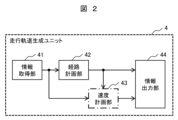
- the traveling trajectory generation unit 4 has an information acquisition unit 41, a route planning unit 42, a speed planning unit 43, and an information output unit 44, as shown in FIG.
- the route planning section 42 based on the traveling situation information transmitted from the operation management unit 3 and acquired by the information acquiring section 41, the route planning section 42 generates a route (hereinafter referred to as "route command value P") that serves as a traveling target when the vehicle travels on the road.
- route command value P a route that serves as a traveling target when the vehicle travels on the road.
- the route command value P is, for example, a command value generated based on either information about the vicinity of the own vehicle acquired by the sensor 14 or the like, or information obtained by synthesizing distant map information recorded in the map information storage unit 13 or the like with the aforementioned near information, but the method of generating the route command value P is not limited.
- the speed planning unit 43 Based on the route command value P and the travel route information, the speed planning unit 43 generates a travel target speed (hereinafter referred to as “speed command value”) when the vehicle travels on the road. Details of the speed planning unit 43 will be described later.
- the travel control unit 5 sets the target driving force, the target braking force, the target steering angle, etc., and controls the powertrain system 6, the brake system 7, and the steering system 8 so that the vehicle follows the travel trajectory output from the travel trajectory generation unit 4.
- Control target group of vehicle motion control device 2 The powertrain system 6 controls the driving force generated by the internal combustion engine, the electric motor, etc. based on the operation by the driver and the target driving force output from the travel control unit 5 .
- the brake system 7 controls the braking force generated by the brake calipers and the like based on the operation by the driver and the target braking force output from the travel control unit 5.
- the steering system 8 controls the steering angle of the wheels based on the driver's operation and the target steering angle output from the travel control unit 5 .
- the speed planning unit 43 generates a speed command value of the vehicle based on the position and speed of the vehicle, the upper limit value of behavior, the route command value P, etc., and has an information acquisition unit 43a, a route characteristic point setting unit 43b, a running speed generation unit 43c, and an information output unit 43d shown in FIG. A description will be given below.
- the information acquisition unit 43a acquires the travel status information from the operation management unit 3, acquires the route command value P from the route planning unit 42, and outputs them to each unit in the speed planning unit 43.
- the route feature point setting unit 43b Based on the route command value P acquired from the information acquisition unit 43a, the route feature point setting unit 43b sets feature points on the route command value P such as the peak point of the curvature and the peak point of the distance differential value of the curvature.
- the path characteristic points set by the path characteristic point setting unit 43b may be a point with zero curvature or a starting point or an end point of the path command value P, and the definition of the path characteristic points is not limited.
- the traveling speed generation unit 43c generates a speed command value when the host vehicle travels the route command value P based on the traveling situation information and the route command value P from the information acquisition unit 43a and the route feature points such as the curvature peak point from the route feature point setting unit 43b.
- the information output unit 43d outputs the speed command value from the traveling speed generation unit 43c to the information output unit 44.
- FIG. 4 is a plan view of the travel route along which the vehicle V travels, and exemplifies the route command value P set within the travelable region R of the vehicle V at a certain time.
- this drivable region R there are an inflection point H at the start point of a left turn and an inflection point N at the end point.
- FIG. 5A is an example of the curvature of a travel route having a transition curve section and a steady curve section on the curve C of the travel route in FIG. 4 and the distance derivative value of the curvature.
- the section from the inflection point H to the inflection point U and the section from the inflection point T to the inflection point N are transition curve sections in which the curvature linearly changes, and since the distance derivative value of the curvature is a constant value, there is no peak point of the distance derivative value of the curvature.
- FIG. 1 the section from the inflection point H to the inflection point U and the section from the inflection point T to the inflection point N are transition curve sections in which the curvature linearly changes, and since the distance derivative value of the curvature is a constant value, there is no peak point of the distance derivative value of the curvature.
- FIG. 5B is an example of the curvature of the travel route having a transition curve section in the curve C of the travel route in FIG. 4 and the distance derivative value of the curvature.
- there is a curvature peak point K and the section from the inflection point H to the curvature peak point K and the section from the curvature peak point K to the inflection point N are transition curve sections in which the curvature changes nonlinearly, and the point W and the point F at which the distance derivative value of curvature peaks in each transition curve section are defined as the peak points of the distance derivative value of curvature.
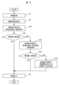
- FIG. 6 is a flow chart of the speed planning unit 43 of the first embodiment.
- step S1 the information acquisition section 43a of the speed planning section 43 acquires the travel status information from the information acquisition section 41 and acquires the route command value P from the route planning section .
- step S2 the route feature point setting unit 43b of the speed planning unit 43 sets route feature points such as the peak point of the curvature on the route command value P (hereinafter referred to as “first route feature point”) and the peak point of the distance differential value of curvature (hereinafter referred to as “second route feature point”) based on the travel situation information and the route command value P acquired in step S1.
- first route feature point the peak point of the curvature on the route command value P
- second route feature point the peak point of the distance differential value of curvature
- step S31 the travel speed generation unit 43c of the speed planning unit 43 generates a speed command value such that the longitudinal acceleration generated when traveling the route command value P is within a specified value, based on the travel situation information and the route command value P acquired in step S1, and the route characteristic points set in step S2.
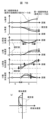
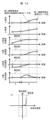
- FIG. 7A is an example of (b) vehicle speed, (c) longitudinal acceleration, (d) lateral acceleration, (e) longitudinal jerk, (f) graph of the distance axis of lateral jerk, and (g) diagram of longitudinal acceleration and lateral acceleration, which occur when the vehicle V travels at a constant speed (broken line) and when the vehicle V travels at the speed command value generated in step S31 (solid line).
- step S31 (when the speed command value in step S31 is used) considers the linkage between the longitudinal motion and the lateral motion, and in order to keep each physical quantity related to vehicle behavior within the specified values indicated by the dashed-dotted lines, (a) the peak point of the curvature (first path characteristic point) is aligned with (c) the zero point of the longitudinal acceleration, and (a) the peak point of the distance differential value of the curvature (second path characteristic point) is aligned with (c) the peak point of the longitudinal acceleration, so that (c) the longitudinal acceleration is within the range of the specified value. is maximized with
- FIG. 7A illustrates a situation in which the use of the speed command value in step S31 slightly improves the riding comfort and comfort of the occupants compared to when the vehicle is traveling at a constant speed, but (d) the lateral acceleration still exceeds the specified value, so further improvement of the speed command value is necessary.
- step S32 the travel speed generation unit 43c of the speed planning unit 43 determines whether or not the physical quantity related to vehicle behavior that occurs when traveling the route command value P is within a specified value based on the speed command value generated in step S31. If the physical quantity relating to vehicle behavior is within the specified value (step S32, YES), the process proceeds to step S4, and if the physical quantity relating to vehicle behavior is greater than the specified value (step S32, NO), the process proceeds to step S33.
- step S33 the travel speed generation unit 43c of the speed planning unit 43 generates a speed command value in which both the longitudinal acceleration and the longitudinal jerk occurring when the vehicle travels along the route command value P are within specified values, based on the travel situation information and the route command value P obtained in step S1, the route characteristic points defined in step S2, and the speed command value generated in step S31.
- FIG. 7B is an example of a physical quantity related to vehicle behavior that occurs when the vehicle V travels with the speed command value generated in step S31 (broken line) and when the vehicle V travels with the speed command value generated in step S33 (solid line), and the configuration of the graph is the same as that of FIG. 7A.
- the solid line in FIG. 7B (when the speed command value in step S33 is used) is such that (c) the peak point of the longitudinal acceleration is set to the peak point of the distance differential value of the curvature in the same manner as in step S31, and (e) the longitudinal jerk is maximized within the specified value in order to keep the physical quantity related to the vehicle behavior within the specified value.
- FIG. 7B illustrates a situation in which the use of the speed command value in step S33 further improves the riding comfort and comfort of the occupants compared to the use of the speed command value in step S31, but (d) the lateral acceleration still exceeds the specified value, so further improvement in the speed command value is necessary.
- step S34 the travel speed generation unit 43c of the speed planning unit 43 determines whether or not the physical quantity related to vehicle behavior occurring when traveling the route command value P is within a specified value based on the speed command value generated in step S33. If the physical quantity relating to vehicle behavior is within the specified value (step S34, YES), the process proceeds to step S4, and if the physical quantity relating to vehicle behavior is greater than the specified value (step S34, NO), the process proceeds to step S35.
- the driving speed generation unit 43C of the speed planning unit 43 is based on the driving status information obtained in step S1, the route command value P, the route feature set in the step S2, and the speed command value generated in step S33, and the deceleration start point is the front (direction to approach your vehicle V).
- a speed command value in which the physical volume related to the vehicle behavior is within the specified value by moving the ending point in the back (the direction away from the vehicle V).
- FIG. 7C is an example of a physical quantity related to vehicle behavior that occurs when the vehicle V travels with the speed command value generated in step S33 (dashed line) and when the vehicle V travels with the speed command value generated in step S35 (solid line), and the configuration of the graph is common to FIGS. 7A and 7B.
- the solid line in FIG. 7C is an example of a physical quantity related to vehicle behavior that occurs when the vehicle V travels with the speed command value generated in step S33 (dashed line) and when the vehicle V travels with the speed command value generated in step S35 (solid line), and the configuration of the graph is common to FIGS. 7A and 7B.
- step S35 (when the speed command value in step S35 is used) is such that (c) the peak point of the longitudinal acceleration is set to the peak point of the distance differential value of the curvature in the same manner as in steps S31 and S33 in order to keep the physical quantity related to the vehicle behavior within the specified value, (e) the longitudinal jerk is maximized within the specified value, and the deceleration start point is set on the straight road S before the connecting point of the straight road S and the curve C so that the physical quantity related to the vehicle behavior is within the specified value ((c) the longitudinal acceleration). (see graph).
- FIG. 7C illustrates a situation in which (c) the longitudinal acceleration and (d) the lateral acceleration are within the specified values by using the speed command value in step S35, and the occupant's riding comfort and comfort are sufficiently ensured.
- step S4 the information output section 43d of the speed planning section 43 outputs the speed command value generated in any one of steps S31, S33, and S35 to the information output section 44 of the travel trajectory generation unit 4. It should be noted that all of the speed command values output in step S4 can keep physical quantities related to vehicle behavior within specified values, so that the travel control unit 5 that receives the speed command values from the information output section 44 can control the powertrain system 6, the brake system 7, and the steering system 8 so as to achieve vehicle control that provides a comfortable ride.
- FIGS. 8A and 8B are other examples of physical quantities related to vehicle behavior that occur when the vehicle V travels with the (a) curvature of the route command value P in FIG. 4 and the speed command value generated in the flowchart shown in FIG. 6, and the graph configuration is common to FIG.
- the (b) specified value of the vehicle speed is constant, but in FIGS. 8A and 8B, the (b) specified value of the vehicle speed is set smaller when traveling on the curve C than when traveling on the straight road S.
- the processing up to step S35 in FIG. 6 is performed in both the situations of FIG. 8A (at the time of entering the curve C) and FIG. 8B (at the time of exiting the curve C), thereby further suppressing the vehicle speed when traveling on the curve C, and (b) keeping the physical quantities related to the vehicle behavior, including the vehicle speed, within the prescribed values.
- the peak point of the longitudinal acceleration is aligned with the peak point of the distance differential value of the curvature, and the zero point of the longitudinal acceleration is aligned with the peak point of the curvature. Then, the range in which the longitudinal acceleration occurs is gradually expanded until the physical quantity related to vehicle behavior falls within the specified value. can be done.
- FIGS. 9 to 10B the vehicle motion control device 2 of Embodiment 2 of the present invention will be described using FIGS. 9 to 10B. Duplicate descriptions of common points with the first embodiment will be omitted.
- FIG. 9 is a flow chart of the speed planning unit 43 of the second embodiment.
- the flow chart of the speed planning unit 43 of the present embodiment shown here is obtained by adding steps S5 to S7 between steps S32, S4 and S33 to the flow chart of the speed planning unit 43 of the first embodiment shown in FIG. That is, in this embodiment, if it is determined in step S32 that the physical quantity based on the speed command value in step S31 is within the specified value, the process proceeds to step S5, and if not, the process proceeds to step S6.
- step S5 the travel speed generation unit 43c of the speed planning unit 43 generates a speed command value after moving the position of the peak point of the longitudinal acceleration forward or backward on the distance axis.
- vehicle control based on the speed command value in step S31 guarantees a ride comfort of at least a certain level.
- this step by correcting the longitudinal jerk of the speed command value in step S31 so as to be smaller, it becomes possible to realize vehicle control that further suppresses unstable behavior of the vehicle and provides a more comfortable ride.
- step S6 the running speed generation unit 43c of the speed planning unit 43 generates a speed command value after moving the position of the longitudinal acceleration peak point forward or backward on the distance axis so that the physical quantity related to vehicle behavior that is greater than the specified value is improved (closer to the specified value). Since it is determined in step S32 that the speed command value in step S31 cannot achieve sufficiently comfortable vehicle control, the process of this step corrects the speed command value generated in step S31 so as to reduce the longitudinal jerk, thereby increasing the possibility of realizing vehicle control that provides a comfortable ride. It should be noted that even after the processing of this step, there are cases where the physical quantity related to vehicle behavior cannot be kept within the specified value, so processing for further improving the speed command value (for example, steps S33 and S35 in FIG. 6) may need to be performed.
- step S7 the travel speed generation unit 43c of the speed planning unit 43 determines whether or not the physical quantity related to vehicle behavior that occurs when traveling the route command value P is within a specified value based on the speed command value in step S6. If the physical quantity relating to vehicle behavior is within the specified value (step S7, YES), the process proceeds to step S4, and if the physical quantity relating to vehicle behavior is greater than the specified value (step S7, NO), the process proceeds to step S33. Thereby, the speed command value in step S6 can be further corrected as required.
- FIG. 10A is an example of a physical quantity related to vehicle behavior that occurs when the vehicle V travels with the speed command value generated in step S31 of Example 1 (dashed line) and when the vehicle V travels with the speed command value generated in step S5 of Example 2 (solid line), and the configuration of the graph is the same as in FIG. 7A of Example 1.
- the solid line in FIG. 10A indicates (c) that the peak point of the longitudinal acceleration is in the near side (in the direction toward the own vehicle V) within a range in which the physical quantity related to vehicle behavior is within a specified value, thereby reducing the jerk in the region where the acceleration is large.
- the peak point of the longitudinal acceleration is set to the front or back within the range in which the physical quantity related to vehicle behavior is within the specified value, thereby reducing the jerk in areas where the acceleration is large, thereby suppressing the unstable behavior of the vehicle and improving the ride comfort of the occupants.
- FIG. 10B is an example of physical quantities related to vehicle behavior that occur when the vehicle V travels with the curvature (a) of the route command value P in FIG.
- the solid line in FIG. 10B has the peak point of the longitudinal acceleration at the back (in the direction away from the own vehicle V) so that the physical quantity related to vehicle behavior is within the specified value.
- the peak point of the longitudinal acceleration is set to the front or the back so that the physical quantity related to the vehicle behavior is within the specified value, so that the physical quantity related to the vehicle behavior can be kept within the specified value while the longitudinal motion and the lateral motion are coordinated, thereby improving the ride comfort of the passenger.
- FIGS. 11 and 12 a vehicle motion control device 2 according to a third embodiment of the present invention will be described with reference to FIGS. 11 and 12.
- FIG. Duplicate descriptions of common points with the first and second embodiments will be omitted.
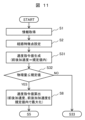
- FIG. 11 is a flow chart of the speed planning unit 43 of the third embodiment.
- the flow chart of the speed planning section 43 of the present embodiment shown here is obtained by adding step S8 between steps S32 and S5 to the flow chart of the speed planning section 43 of the second embodiment shown in FIG.
- step S8 the traveling speed generation unit 43c of the speed planning unit 43 generates a speed command value that does not make the longitudinal acceleration at the curvature peak point zero when the physical quantity related to the vehicle behavior occurring in the own vehicle V traveling based on the speed command value in step S31 is within a specified value.
- FIG. 12 shows an example of the physical quantity related to the vehicle behavior that occurs when the own vehicle V travels with the (a) curvature of the route command value P in FIG.
- (c) longitudinal acceleration and (e) longitudinal jerk are maximized within a range in which physical quantities related to vehicle behavior fall within specified values.
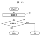
- FIG. 13 is a flow chart of the speed planning unit 43 of the fourth embodiment.
- the flowchart of this embodiment shown here is obtained by adding step S9 between steps S1 and S2 to the flowchart of the first embodiment shown in FIG. 6, the flowchart of the second embodiment shown in FIG. 9, and the flowchart of the third embodiment shown in FIG.
- step S9 the speed planning unit 43 determines whether or not to generate a speed command value based on a flag generated by a controller higher than the speed planning unit 43 (for example, the operation management unit 3). If the flag indicates that the process is prohibited (step S9, YES), the process is terminated and no speed command value is generated. On the other hand, if the flag indicates that processing is permitted (step S9, NO), the process proceeds to step 2 and subsequent steps to generate a desired speed command value.
- a flag generated by a controller higher than the speed planning unit 43 for example, the operation management unit 3
- the host controller prohibits the generation of a speed command value that improves ride comfort, for example, in an emergency such as when avoiding a preceding vehicle that has suddenly stopped, by shifting to the host controller's speed control that emphasizes avoidance performance, it is possible to avoid a rear-end collision with the preceding vehicle, even though the ride comfort will deteriorate, thereby improving safety.
- FIG. 14 is a functional block diagram of the speed planning unit 43 of the fifth embodiment.
- the speed planning unit 43 of the present embodiment shown here is obtained by changing the traveling speed generation unit 43c of the speed planning unit 43 of the first embodiment shown in FIG.
- the running speed candidate generation unit 43e Based on the travel status information and the route command value P acquired by the information acquisition unit 43a, the running speed candidate generation unit 43e generates a plurality of speed command values in which the physical quantity related to the vehicle behavior that occurs when traveling the route command value P is within a specified value, and outputs them to the running speed selection unit 43f.
- the travel speed selection unit 43f selects one speed command value based on the current travel mode (shortest time mode, economy mode, etc.) indicated by the travel situation information from the information acquisition unit 43a and a plurality of speed command value candidates from the travel speed candidate generation unit 43e, and the information output unit 43d outputs it to the travel control unit 5.
- the speed command value candidate with the shortest travel time is selected from among the plurality of speed command value candidates generated by the driving speed candidate generation unit 43e
- the speed command value candidate with the minimum energy consumption is selected from among the plurality of speed command value candidates. That is, the travel speed selection unit 43f selects the speed command value with the shortest movement time from among the multiple speed command value candidates, or selects the speed command value with the minimum energy consumption from the multiple speed command value candidates.
- the specified value setting unit 31 of the operation management unit 3 of this embodiment may set a plurality of specified values based on the mass, size and arrangement of the vehicle occupants and cargo, and the state of the route on which the vehicle travels.
- the running speed candidate generation unit 43e can generate a plurality of speed command values according to the number of passengers, seating positions, etc.
- the running speed selection unit 43f selects a speed command value according to the number of passengers, etc., thereby further improving the ride comfort when the vehicle is running.
- the vehicle motion control device of the fifth embodiment not only can the same effects as those of the first to fourth embodiments be obtained, but also the vehicle motion can be controlled according to the selection of the driving mode and the mounting condition of the vehicle.
- the present invention is not limited to the above-described embodiments, and includes various modifications.
- the above-described embodiments are specifically described in order to explain the present invention in an easy-to-understand manner, and are not necessarily limited to those having all the configurations described.
- part of the configuration of one embodiment can be replaced with part of the configuration of another embodiment.
- the configuration of another embodiment can be added to the configuration of one embodiment.
- a part of the configuration of each embodiment can be deleted, a part of another configuration can be added, and a part of another configuration can be substituted.
Abstract
本発明は、走行中の車両に生じる前後運動と横運動の連係を考慮した上で、加速度や加加速度などの物理量が規定値内になるように速度を設定することで、乗り心地と移動時間の最短化を両立する車両運動制御装置を提供する。車両が走行する経路を生成する経路指令値算出手段と、前記経路を走行する際の車両挙動の物理量の規定値を設定する規定値設定手段と、前記経路と前記規定値に基づいて経路特徴点を設定する経路特徴点設定手段と、前記経路と前記規定値と前記経路特徴点に基づいて前記車両が前記経路を走行するための速度を算出する速度指令値算出手段を備え、前記速度指令値算出手段は、前記経路の曲率のピーク点である経路特徴点に基づいて前後加速度のゼロ点を設定し、前記曲率の距離微分値のピーク点である経路特徴点に基づいて前後加速度のピーク点を設定することを特徴とする車両運動制御装置。
Description
本発明は、走行経路に応じて車両の運動を制御する車両運動制御装置、および、車両運動制御方法に関する。
運転支援や自動運転に代表される車両運動制御技術の一種として、車両の走行目標となる走行経路や走行速度といった情報で構成される走行軌道を生成し、その走行軌道に沿って車両が走行するようにパワートレイン、ブレーキ、ステアリングなどを制御する技術が知られている。最も単純な走行経路制御としては、例えば、車線中央を走行経路に設定する車線維持制御がある。
また、より高度な走行経路制御技術としては、例えば、特許文献1に開示されるものがあり、特許文献1の請求項1の後段には、「前記走行路状況情報に基づいて、前後加速度及び横加速度のタイヤグリップ限界による第1摩擦円特性を、タイヤグリップ限界による前後加速度値及び横加速度値以下に制約する制約条件を算出し、前記制約条件を用い、前記目標軌跡に沿う目標速度プロファイルを生成し、前記自車が前記目標軌跡に沿って走行するとき、前記目標速度プロファイルに従った走行支援を行う」走行支援方法が記載されている。
このように、特許文献1には、将来の走行路の走行路曲率等に起因するタイヤグリップ限界を想定した走行支援方法を対象としており、自車が目標軌跡に沿って走行するシーンにおいて、タイヤグリップ限界による制約条件に基づいて自車の目標速度プロファイルを生成することで自車前方の走行路状況にかかわらず目標軌跡から自車走行軌跡が逸脱するのを抑える走行支援方法が開示されている。
しかし、特許文献1の走行支援方法は、タイヤグリップ限界に基づいて前後加速度や横加速度のピーク値を抑制する技術に留まり、乗員の乗り心地や快適性を改善する技術ではない。従って、特許文献1の技術を利用して、前後加速度や横加速度のピーク値を抑制すると、車速低下を補うために加減速の回数が増加したり、車両の挙動が不安定になったりするなど、乗員の乗り心地や快適性を損ねることもあった。
そこで、本発明は、走行経路の曲率のピーク点と自車両の前後加速度のゼロ点などを合わせるといった前後運動と横運動の連係を考慮した上で加速度や加加速度などの車両挙動に関する物理量が規定値内になるように自車両の速度を設定することで、乗員の乗り心地や快適性を改善する車両運動制御装置を提供することを目的とする。
上記した課題を解決するため、本発明の車両運動制御装置は、車両が走行する経路を生成する経路計画部と、前記経路を走行する際の車両挙動の物理量の規定値を設定する規定値設定部と、前記経路と前記規定値に基づいて経路特徴点を設定する経路特徴点設定部と、前記経路と前記規定値と前記経路特徴点に基づいて前記車両が前記経路を走行するための速度指令値を生成する走行速度生成部を備え、前記走行速度生成部は、前記経路の曲率のピーク点である経路特徴点に基づいて前後加速度のゼロ点を設定し、前記曲率の距離微分値のピーク点である経路特徴点に基づいて前後加速度のピーク点を設定する車両運動制御装置とした。
本発明の車両運動制御装置または車両運動制御方法によれば、走行経路の曲率のピーク点と自車両の前後加速度のゼロ点などを合わせるといった前後運動と横運動の連係を考慮した上で加速度や加加速度などの車両挙動に関する物理量が規定値内になるように自車両の速度を設定することで、乗員の乗り心地や快適性を改善することができる。なお、上記した以外の課題、構成及び効果については、下記する実施例の説明により、明らかにされる。
以下、本発明の車両運動制御装置の実施例を、図面を使用して説明する。なお、実質的に同一又は類似する構成には同一の符号を付し、説明が重複する場合には、その説明を省略する場合がある。また、周知技術についても、その説明を省略する場合がある。
まず、図1から図8を用い、本発明の実施例1の車両運動制御装置2を説明する。
<車載システム1>
図1は、本実施例の車両運動制御装置2を有する車載システム1の機能ブロック図である。車載システム1は、自車両に搭載され、運転支援や自動運転などの車両運動制御を実行するためのシステムであり、図示するように、車外通信装置11、GNSS(Global Navigation Satellite System)12、地図情報記憶部13、センサ14、HMI(human machine interface)ユニット15、車両運動制御装置2、パワートレインシステム6、ブレーキシステム7、ステリングシステム8を有する。以下、順次説明する。
図1は、本実施例の車両運動制御装置2を有する車載システム1の機能ブロック図である。車載システム1は、自車両に搭載され、運転支援や自動運転などの車両運動制御を実行するためのシステムであり、図示するように、車外通信装置11、GNSS(Global Navigation Satellite System)12、地図情報記憶部13、センサ14、HMI(human machine interface)ユニット15、車両運動制御装置2、パワートレインシステム6、ブレーキシステム7、ステリングシステム8を有する。以下、順次説明する。
<車両運動制御装置2の情報源群>
車外通信装置11は、無線通信により、自車両と他車両の間の車車間通信、又は、自車両と路側機の間の路車間通信を実行し、車両や周辺環境などの情報を、送受信する。
車外通信装置11は、無線通信により、自車両と他車両の間の車車間通信、又は、自車両と路側機の間の路車間通信を実行し、車両や周辺環境などの情報を、送受信する。
GNSS12は、準天頂衛星やGPS(Global Positioning System)衛星などの人工衛星から発信される電波を受信し、自車両の位置などの情報を取得する。
地図情報記憶部13は、ナビゲーションシステムなどで使用される一般的な道路情報、道路の幅や道路の曲率などのカーブに関する情報を有する道路情報、路面状況や交通状況などの情報、他車両の走行状態の情報である、車両や周辺環境などの情報を記憶する。なお、車両や周辺環境などの情報は、車外通信装置11を介して、車車間通信や路車間通信で取得される情報により、逐次更新される。
センサ14は、画像センサ、ミリ波レーダ、ライダーなどの車両や周辺環境などの情報を検出する外界認識センサや、ドライバによる操作、車両の速度、加速度、加加速度、角速度、車輪の操舵角などの情報を検出するセンサである。外界認識センサにより検出する車両や周辺環境などの情報は、例えば、自車両の周辺に存在する障害物、標識、車線境界線、車線外側線、建造物、歩行者、他の車両などの各種物体の情報である。また、センサ14は、例えば、画像センサが撮像する画像データの白線と路面の輝度との差に基づいて、車線境界線や車線外側線などを認識する。
HMIユニット15は、走行モードの選択や目的地の設定などのユーザの入力操作により受け付けられる情報、車外通信装置11、GNSS12、センサ14により取得される情報、地図情報記憶部13に記録される情報から、ユーザが必要とする情報を、ディスプレイに表示し、スピーカから音声案内する。また、HMIユニット15は、ユーザに注意喚起する警報を発生する。
ここで、走行モードには、例えば、コンフォートモード、エコノミモード、スポーツモードなどがあり、走行モードは、ユーザが任意に設定し、若しくは、ユーザが予め設定し、又は、走行状況情報に基づいて後述の運行管理ユニット3により設定され、車両の速度、加速度、加加速度などが設定される。そのため、運行管理ユニット3の規定値設定部31は、設定された走行モードに応じて、車両の挙動の規定値を変化させる。なお、走行モードには、移動時間を最短にする最短時間モードや、移動距離を最短にする最短距離モードなどがある。
<車両運動制御装置2>
車両運動制御装置2は、図1に示すように、運行管理ユニット3、走行軌道生成ユニット4、走行制御ユニット5を有する。この車両運動制御装置2は、具体的には、CPU(Central Processing Unit)などの演算装置、半導体メモリなどの主記憶装置や補助記憶装置、及び、通信装置などのハードウェアを有し、車両を統括制御するECU(Electronic Control Unit)であり、主記憶装置にロードされるプログラムを演算装置で実行することにより、運行管理ユニット3等の様々な機能を実現するものである。なお、本実施例では、説明の都合上、運行管理ユニット3、走行軌道生成ユニット4、走行制御ユニット5は分離した構成を有するが、必ずしも分離した構成を有する必要はなく、これらユニットを実際の車両に使用する場合には、上位のコントローラにより、これらユニットの様々な機能を実現してもよい。
車両運動制御装置2は、図1に示すように、運行管理ユニット3、走行軌道生成ユニット4、走行制御ユニット5を有する。この車両運動制御装置2は、具体的には、CPU(Central Processing Unit)などの演算装置、半導体メモリなどの主記憶装置や補助記憶装置、及び、通信装置などのハードウェアを有し、車両を統括制御するECU(Electronic Control Unit)であり、主記憶装置にロードされるプログラムを演算装置で実行することにより、運行管理ユニット3等の様々な機能を実現するものである。なお、本実施例では、説明の都合上、運行管理ユニット3、走行軌道生成ユニット4、走行制御ユニット5は分離した構成を有するが、必ずしも分離した構成を有する必要はなく、これらユニットを実際の車両に使用する場合には、上位のコントローラにより、これらユニットの様々な機能を実現してもよい。
運行管理ユニット3は、車外通信装置11、GNSS12、センサ14により取得される情報、地図情報記憶部13に記録される地図情報に基づいて、自車両の位置の情報、自車両の周辺に存在する各種物体の情報(車両や周辺環境などの情報)、横加速度、ヨーレイト、横加加速度といった車両の挙動に関する情報を生成する。また、運行管理ユニット3は、これら自車両の位置の情報、各種物体の情報、車両の挙動に関する情報を、車外通信装置11を介して、定期的に他の車両や路側機に送信すると共に、地図情報記憶部13にも送信し、地図情報記憶部13に記憶される地図情報を逐次更新する。さらに、運行管理ユニット3は、これら自車両の位置の情報、各種物体の情報、車両の挙動に関する情報や、HMIユニット15により受け付けられる情報(例えば、走行モードや目的地)に基づいて、車両の現在位置から目的地までの経路の情報を設定する。ここで設定される経路の情報には、運行管理ユニット3の規定値設定部31が走行モードに応じて設定する、車両の挙動の規定値が含まれる。なお、以下、運行管理ユニット3により、生成される情報や設定される情報を、「走行状況情報」と称する場合がある。
走行軌道生成ユニット4は、図2に示すように、情報取得部41、経路計画部42、速度計画部43、情報出力部44を有する。走行軌道生成ユニット4は、運行管理ユニット3から送信されて情報取得部41で取得した走行状況情報に基づいて、経路計画部42では車両が道路を走行する際の走行目標となる経路(以下「経路指令値P」と称する)を生成する。ここで、経路指令値Pは、例えば、センサ14などで取得した自車両の近傍の情報、または、地図情報記憶部13などに記録されている遠方の地図情報と前述の近傍の情報を合成した情報、の何れかに基づいて生成した指令値であるが、経路指令値Pの生成方法は限定しない。そして、速度計画部43では、経路指令値Pと走行経路情報に基づいて車両が道路を走行する際の走行目標となる速度(以下「速度指令値」と称する)を生成し、情報出力部44では経路指令値Pと速度指令値といった情報で構成される走行軌道を走行制御ユニット5に出力する。なお、速度計画部43の詳細は後述する。
走行制御ユニット5は、走行軌道生成ユニット4から出力される走行軌道に、車両が追従して走行するように、目標駆動力、目標制動力、目標操舵角などを設定し、パワートレインシステム6、ブレーキシステム7、ステアリングシステム8を制御する。
<車両運動制御装置2の制御対象群>
パワートレインシステム6は、ドライバによる操作や走行制御ユニット5から出力される目標駆動力に基づいて、内燃機関や電動機などにより発生する駆動力を制御する。
パワートレインシステム6は、ドライバによる操作や走行制御ユニット5から出力される目標駆動力に基づいて、内燃機関や電動機などにより発生する駆動力を制御する。
ブレーキシステム7は、ドライバによる操作や走行制御ユニット5から出力される目標制動力に基づいて、ブレーキキャリパなどにより発生する制動力を制御する。
ステアリングシステム8は、ドライバによる操作や走行制御ユニット5から出力される目標操舵角に基づいて、車輪の操舵角を制御する。
<速度計画部43>
次に、図3の機能ブロック図を用いて、速度計画部43の詳細を説明する。速度計画部43は、車両の位置や速度、挙動の上限値、経路指令値Pなどに基づいて、車両の速度指令値を生成するものであり、図3に示す、情報取得部43a、経路特徴点設定部43b、走行速度生成部43c、情報出力部43dを有する。以下、順次説明する。
次に、図3の機能ブロック図を用いて、速度計画部43の詳細を説明する。速度計画部43は、車両の位置や速度、挙動の上限値、経路指令値Pなどに基づいて、車両の速度指令値を生成するものであり、図3に示す、情報取得部43a、経路特徴点設定部43b、走行速度生成部43c、情報出力部43dを有する。以下、順次説明する。
情報取得部43aは、運行管理ユニット3から走行状況情報を取得するとともに、経路計画部42から経路指令値Pを取得し、それらを速度計画部43内の各部に出力する。
経路特徴点設定部43bは、情報取得部43aから取得した経路指令値Pに基づいて、曲率のピーク点や曲率の距離微分値のピーク点といった経路指令値P上の特徴点を設定する。ここで、経路特徴点設定部43bで設定される経路特徴点は、曲率がゼロの点や、経路指令値Pの始点や終点であっても良く、経路特徴点の定義を限定しない。
走行速度生成部43cは、情報取得部43aからの走行状況情報と経路指令値P、経路特徴点設定部43bからの曲率のピーク点などの経路特徴点に基づいて、自車両が経路指令値Pを走行する際の速度指令値を生成する。
情報出力部43dは、走行速度生成部43cからの速度指令値を情報出力部44へ出力する。
<経路特徴点設定部43bの処理>
次に、図4の走行経路を走行する状況下で時々刻々と生成される経路特徴点について、図5Aと図5Bを用いて説明する。
次に、図4の走行経路を走行する状況下で時々刻々と生成される経路特徴点について、図5Aと図5Bを用いて説明する。
図4は、自車両Vが走行する走行経路の平面図であり、ある時間において自車両Vの走行可能領域Rの範囲内に設定された経路指令値Pを例示したものである。この走行可能領域Rには、左旋回の始点に変曲点H、終点に変曲点Nが存在し、変曲点Hまでの区間を直線路Sと定義し、変曲点Hから変曲点Nまでの区間をカーブCと定義し、変曲点N以降の区間を直線路Mと定義する。
図5Aは、図4の走行経路のカーブCに緩和曲線区間と定常曲線区間がある走行経路の曲率と曲率の距離微分値の一例である。図5Aは、変曲点H以降で曲率が一定値に変化する変曲点U、変曲点U以降で曲率が一定値から変化する変曲点Tが存在し、変曲点Uと変曲点Tを曲率のピーク点と定義する。変曲点Hから変曲点Uまでの区間と、変曲点Tから変曲点Nまでの区間は、曲率が線形に変化する緩和曲線区間であり、曲率の距離微分値がそれぞれ一定値であるため、曲率の距離微分値のピーク点というものは存在しないが、図5Aでは変曲点Hと変曲点Uの中間点Qと、変曲点Tと変曲点Nの中間点Zを曲率の距離微分値のピーク点と定義する。
図5Bは、図4の走行経路のカーブCに緩和曲線区間がある走行経路の曲率と曲率の距離微分値の一例である。図5Bは、曲率のピーク点Kが存在し、変曲点Hから曲率のピーク点Kまでの区間と、曲率のピーク点Kから変曲点Nまでの区間は、曲率が非線形に変化する緩和曲線区間であり、各緩和曲線区間で曲率の距離微分値がピークになる点Wと点Fを曲率の距離微分値のピーク点と定義する。
<速度計画部43の処理の一例>
次に、図6から図7Cを用いて、自車両Vが図4の走行経路を走行する状況下で、速度計画部43で時々刻々と生成される速度指令値を説明する。
次に、図6から図7Cを用いて、自車両Vが図4の走行経路を走行する状況下で、速度計画部43で時々刻々と生成される速度指令値を説明する。
図6は、実施例1の速度計画部43のフローチャートである。
まず、ステップS1では、速度計画部43の情報取得部43aは、情報取得部41から走行状況情報を取得し、経路計画部42から経路指令値Pを取得する。
次に、ステップS2では、速度計画部43の経路特徴点設定部43bは、ステップS1で取得した走行状況情報と経路指令値Pに基づいて、経路指令値P上の曲率のピーク点(以下、「第一経路特徴点」と称する)や、曲率の距離微分値のピーク点(以下、「第二経路特徴点」と称する)などの経路特徴点を設定する。
ステップS31では、速度計画部43の走行速度生成部43cは、ステップS1で取得した走行状況情報と経路指令値Pと、ステップS2で設定した経路特徴点に基づいて、経路指令値Pを走行する際に生じる前後加速度が規定値以内になる速度指令値を生成する。
図7Aは、図4の経路指令値Pの(a)曲率と、自車両Vが定速走行する場合(破線)と、ステップS31で生成された速度指令値で走行する場合(実線)に生じる、(b)車速と、(c)前後加速度と、(d)横加速度と、(e)前後加加速度と、(f)横加加速度の距離軸のグラフ、および、(g)前後加速度と横加速度のダイアグラムの一例である。図7Aの実線(ステップS31の速度指令値使用時)は、前後運動と横運動の連係を考慮すると共に、車両挙動に関する各物理量を一点鎖線で示す規定値内にするため、(a)曲率のピーク点(第一経路特徴点)に(c)前後加速度のゼロ点を合わせ、さらに、(a)曲率の距離微分値のピーク点(第二経路特徴点)に(c)前後加速度のピーク点を合わせることで、(c)前後加速度を規定値の範囲内で最大化している。
なお、図7A(d)、(g)での破線と実線の比較から分かるように、図7Aは、定速走行時に比べ、ステップS31の速度指令値の利用により、乗員の乗り心地や快適性が若干改善されるものの、(d)横加速度は未だ規定値を超えるため、速度指令値の更なる改善が必要である状況を例示したものである。
ステップS32では、速度計画部43の走行速度生成部43cは、ステップS31で生成した速度指令値に基づいて、経路指令値Pを走行する際に生じる車両挙動に関する物理量が規定値以内か否かを判定する。そして、車両挙動に関する物理量が規定値以内の場合(ステップS32、YES)はステップS4に進み、車両挙動に関する物理量が規定値より大きい場合(ステップS32、NO)はステップS33に進む。
ステップS33では、速度計画部43の走行速度生成部43cは、ステップS1で取得した走行状況情報と経路指令値Pと、ステップS2で定義した経路特徴点、ステップS31で生成した速度指令値に基づいて、経路指令値Pを走行する際に生じる前後加速度と前後加加速度が共に規定値以内になる速度指令値を生成する。
図7Bは、図4の経路指令値Pの(a)曲率と、自車両VがステップS31で生成された速度指令値で走行する場合(破線)と、ステップS33で生成された速度指令値で走行する場合(実線)に生じる車両挙動に関する物理量の一例であり、グラフの構成は図7Aと共通である。図7Bの実線(ステップS33の速度指令値使用時)は、車両挙動に関する物理量を規定値内にするため、(c)前後加速度のピーク点をステップS31と同様に曲率の距離微分値のピーク点とした上で、(e)前後加加速度を規定値内で最大化している。
なお、図7B(d)、(g)での破線と実線の比較から分かるように、図7Bは、ステップS31の速度指令値の利用時に比べ、ステップS33の速度指令値の利用により、乗員の乗り心地や快適性は更に改善されるものの、(d)横加速度は未だ規定値を超えるため、速度指令値の更なる改善が必要である状況を例示したものである。
ステップS34では、速度計画部43の走行速度生成部43cは、ステップS33で生成した速度指令値に基づいて、経路指令値Pを走行する際に生じる車両挙動に関する物理量が規定値以内か否かを判定する。そして、車両挙動に関する物理量が規定値以内の場合(ステップS34、YES)はステップS4に進み、車両挙動に関する物理量が規定値より大きい場合(ステップS34、NO)はステップS35に進む。
ステップS35では、速度計画部43の走行速度生成部43cは、ステップS1で取得した走行状況情報と経路指令値Pと、ステップS2で設定した経路特徴点、ステップS33で生成した速度指令値に基づいて、減速時であれば減速開始点を手前(自車両Vに近づく方向)に移動させ、加速時であれば加速終了点を奥(自車両Vから離れる方向)に移動させることで車両挙動に関する物理量が規定値内になる速度指令値を生成する。
図7Cは、図4の経路指令値Pの(a)曲率と、自車両VがステップS33で生成された速度指令値で走行する場合(破線)と、ステップS35で生成された速度指令値で走行する場合(実線)に生じる車両挙動に関する物理量の一例であり、グラフの構成は図7Aや図7Bと共通である。図7Cの実線(ステップS35の速度指令値使用時)は、車両挙動に関する物理量を規定値内にするため、(c)前後加速度のピーク点をステップS31やステップS33と同様に曲率の距離微分値のピーク点とし、(e)前後加加速度を規定値内で最大化した上で、車両挙動に関する物理量が規定値内になるように減速開始点を直線路SとカーブCの接続点より手前の直線路S上にしている((c)前後加速度のグラフを参照)。
なお、図7C(d)、(g)での破線と実線の比較から分かるように、図7Cは、ステップS35の速度指令値の利用により、(c)前後加速度に加え、(d)横加速度も規定値内となり、乗員の乗り心地や快適性を十分に確保できた状況を例示したものである。
ステップS4では、速度計画部43の情報出力部43dは、ステップS31、ステップS33、ステップS35の何れかで生成した速度指令値を、走行軌道生成ユニット4の情報出力部44へ出力する。なお、ステップS4で出力する速度指令値は何れも、車両挙動に関する物理量を規定値内に収めることができるものであるため、情報出力部44からの速度指令値を受信する走行制御ユニット5は、乗り心地の良い車両制御を実現するように、パワートレインシステム6、ブレーキシステム7、ステアリングシステム8を制御することができる。
<速度計画部43の処理の別例>
次に、図8A、図8Bを用いて、速度計画部43の処理の別例を説明する。図8A、図8Bは、図4の経路指令値Pの(a)曲率と、自車両Vが図6で示したフローチャートで生成された速度指令値で走行する場合に生じる車両挙動に関する物理量の別例であり、グラフの構成は図7Aなどと共通である。
次に、図8A、図8Bを用いて、速度計画部43の処理の別例を説明する。図8A、図8Bは、図4の経路指令値Pの(a)曲率と、自車両Vが図6で示したフローチャートで生成された速度指令値で走行する場合に生じる車両挙動に関する物理量の別例であり、グラフの構成は図7Aなどと共通である。
図7A~図7Cでは、(b)車速の規定値を一定としていたが、図8Aと図8Bでは、(b)車速の規定値を直線路Sの走行時のものよりカーブCの走行時のものを小さくした。この場合、図8A(カーブCへの進入時)と図8B(カーブCからの退出時)の何れの状況下でも、図6のステップS35までの処理が行われることで、カーブC走行時の車速をより抑制しながら、(b)車速を含む車両挙動に関する物理量を規定値内にしている。
これにより、乗り心地の良い車速でカーブCを走行しつつ、加速度や加加速度を規定値内に収めることができる。
これにより、乗り心地の良い車速でカーブCを走行しつつ、加速度や加加速度を規定値内に収めることができる。
このように、図7Aから図8Bに例示した本実施例の速度制御では、前後運動と横運動を連係させるために前後加速度のピーク点を曲率の距離微分値のピーク点、前後加速度のゼロ点を曲率のピーク点に合わせた上で、車両挙動に関する物理量が規定値内になるまで徐々に前後加速度が生じる範囲を広げることで、速度低下を極力抑えながら、車両挙動に関する物理量を、乗員の乗り心地や快適性を損なわない規定値以内に収めることができる。
次に、図9から図10Bを用いて、本発明の実施例2の車両運動制御装置2を説明する。なお、実施例1との共通点は重複説明を省略する。
図9は、実施例2の速度計画部43のフローチャートである。ここに示す本実施例の速度計画部43のフローチャートは、図6に示した実施例1の速度計画部43のフローチャートに対して、ステップS32とステップS4およびステップS33の間に、ステップS5からステップS7を追加したものである。すなわち、本実施例では、ステップS32で、ステップS31の速度指令値による物理量が規定値以内と判定すればステップS5に進み、そうでなければステップS6に進むようにした。
ステップS5では、速度計画部43の走行速度生成部43cは、前後加速度のピーク点の位置を距離軸上で手前または奥に移動させた上で速度指令値を生成する。ステップS32での判定により、ステップS31の速度指令値による車両制御には一定以上の乗り心地が保証されるが、本ステップにて、ステップS31の速度指令値の前後加加速度をより小さくなるように修正することで、車両の不安定挙動を更に抑制した、より乗り心地の良い車両制御を実現することができるようになる。
一方、ステップS6では、速度計画部43の走行速度生成部43cは、規定値より大きい車両挙動に関する物理量が改善される(規定値に近づく)ように、前後加速度のピーク点の位置を距離軸上で手前または奥に移動させた上で速度指令値を生成する。ステップS32での判定により、ステップS31の速度指令値では十分に乗り心地の良い車両制御が実現できないと判定されているため、本ステップの処理により、ステップS31で生成した速度指令値の前後加加速度をより小さくなるように修正することで、乗り心地の良い車両制御を実現できる可能性が高まる。なお、本ステップの処理を経ても、車両挙動に関する物理量を規定値以内にできない場合もあるため、速度指令値を更に改良するための処理(例えば、図6のステップS33、S35)の実施が必要となる場合もある。
そこで、ステップS7では、速度計画部43の走行速度生成部43cは、ステップS6の速度指令値に基づいて、経路指令値Pを走行する際に生じる車両挙動に関する物理量が規定値以内か否かを判定する。そして、車両挙動に関する物理量が規定値以内の場合(ステップS7、YES)はステップS4に進み、車両挙動に関する物理量が規定値より大きい場合(ステップS7、NO)はステップS33に進む。これにより、必要に応じて、ステップS6の速度指令値を更に修正することができる。
図10Aは、図4の経路指令値Pの(a)曲率と、自車両Vが実施例1のステップS31で生成された速度指令値で走行する場合(破線)と、実施例2のステップS5で生成された速度指令値で走行する場合(実線)に生じる車両挙動に関する物理量の一例であり、グラフの構成は実施例1の図7Aなどと共通である。図10Aの実線は、(c)前後加速度のピーク点を車両挙動に関する物理量が規定値以内に収まる範囲で手前(自車両Vに近づく方向)にしており、それにより加速度が大きい領域での加加速度が小さくなる。
このように図10Aに例示した本実施例の速度制御では、前後加速度のピーク点を車両挙動に関する物理量が規定値以内に収まる範囲で手前または奥にすることで、加速度が大きい領域での加加速度を小さくする事で車両の不安定挙動を抑制し、乗員の乗り心地が向上する。
一方、図10Bは、図4の経路指令値Pの(a)曲率と、自車両Vが実施例1のステップS31で生成された速度指令値で走行する場合(破線)と、実施例2のステップS6で生成された速度指令値で走行する場合(実線)に生じる車両挙動に関する物理量の一例であり、グラフの構成は実施例1の図7Aなどと共通である。図10Bの実線は、前後加速度のピーク点を車両挙動に関する物理量が規定値以内に収まるように奥(自車両Vから離れる方向)にしている。
このように図10Bに例示した本実施例の速度制御では、前後加速度のピーク点を車両挙動に関する物理量が規定値以内に収まるように手前または奥にすることで、前後運動と横運動を連係させながら、車両挙動に関する物理量を規定値以内にできるため、乗員の乗り心地が向上する。
次に、図11と図12を用いて、本発明の実施例3の車両運動制御装置2を説明する。
なお、実施例1や実施例2との共通点は重複説明を省略する。
なお、実施例1や実施例2との共通点は重複説明を省略する。
図11は、実施例3の速度計画部43のフローチャートである。ここに示す本実施例の速度計画部43のフローチャートは、図9に示した実施例2の速度計画部43のフローチャートに対して、ステップS32とステップS5の間に、ステップS8を追加したものである。
ステップS8では、速度計画部43の走行速度生成部43cは、ステップS31の速度指令値に基づいて走行した自車両Vに生じる車両挙動に関する物理量が規定値以内の場合に、曲率のピーク点の前後加速度をゼロにしない速度指令値を生成する。
図12は、図4の経路指令値Pの(a)曲率と、自車両VがステップS8で生成された速度指令値で走行する場合に生じる車両挙動に関する物理量の一例であり、グラフの構成は実施例1の図7Aなどと共通である。図12は、(c)前後加速度と(e)前後加加速度を車両挙動に関する物理量が規定値以内に収まる範囲で最大化している。
このように、図12に例示した本実施例の速度制御では、前後加速度と前後加加速度を車両挙動に関する物理量が規定値以内に収まる範囲で最大化することで、不必要な加減速による振動の発生や車速の低下を抑制できるため、乗員の乗り心地が向上すると共に、移動時間を短縮することができる。
次に、図13を用いて、本発明の実施例4の車両運動制御装置2を説明する。なお、実施例1から実施例3との共通点は重複説明を省略する。
図13は、実施例4の速度計画部43のフローチャートである。ここに示す本実施例のフローチャートは、図6に示した実施例1のフローチャート、図9に示した実施例2のフローチャート、図11に示した実施例3のフローチャートに対して、ステップS1とステップS2の間に、ステップS9を追加したものである。
ステップS9では、速度計画部43は、速度計画部43より上位のコントローラ(例えば、運行管理ユニット3)で生成されたフラグに基づいて、速度指令値を生成するか否かを判定する。そして、フラグが処理禁止である場合(ステップS9、YES)は処理を終了し、速度指令値を生成しない。一方、フラグが処理許可である場合(ステップS9、NO)はステップ2以降の処理に進み、所望の速度指令値を生成する。
これにより、例えば急停車した先行車を回避する緊急時等に、上位コントローラによって、乗り心地を改善する速度指令値の生成処理が禁止された場合には、回避性能を重視した上位コントローラの速度制御に移行させることで、乗り心地の悪化を招くものの先行車への追突を回避できるため、安全性が向上する。
次に、図14を用いて、本発明の実施例5の車両運動制御装置2を説明する。なお、実施例1から実施例4との共通点は重複説明を省略する。
図14は、実施例5の速度計画部43の機能ブロック図である。ここに示す本実施例の速度計画部43は、図3に示した実施例1の速度計画部43の走行速度生成部43cを走行速度候補生成部43eに変更し、さらに、走行速度選択部43fを追加したものである。
走行速度候補生成部43eは、情報取得部43aが取得した走行状況情報と経路指令値Pに基づいて、経路指令値Pを走行する時に生じる車両挙動に関する物理量が規定値以内になる複数の速度指令値を生成し、走行速度選択部43fに出力する。
走行速度選択部43fは、情報取得部43aからの走行状況情報が示す現状の走行モード(最短時間モードやエコノミモードなど)、及び、走行速度候補生成部43eからの複数の速度指令値候補に基づいて、1つを速度指令値として選択し、情報出力部43dが走行制御ユニット5に出力する。
例えば、走行状況情報が最短時間モードを示す場合には、走行速度候補生成部43eが生成した複数の速度指令値候補の中から、移動時間が最短の速度指令値候補を選択し、走行状況情報がエコノミモードを示す場合には、複数の速度指令値候補の中から消費エネルギが最小の速度指令値候補を選択する。つまり、走行速度選択部43fでは、複数の速度指令値候補の中から移動時間が最短の速度指令値を選択したり、複数の速度指令値候補から消費エネルギが最小の速度指令値を選択したりする。
また、走行速度候補生成部43eで複数の速度指令値を生成できるようにするため、本実施例の運行管理ユニット3の規定値設定部31では、車両の乗員や積み荷の質量や大きさや配置や、車両が走行する経路の状態に基づいて複数の規定値を設定しても良い。これにより、走行速度候補生成部43eでは、乗員の人数や着座位置等に応じた複数の速度指令値を生成できるため、走行速度選択部43fでは、乗員の人数等に応じた速度指令値を選択することで、車両走行時の乗り心地を更に改善することができる。
このように、実施例5の車両運動制御装置によれば、実施例1から実施例4と同様の効果が得られるだけでなく、走行モードの選択や、車両の搭載状況に応じて車両運動を制御することができる。
なお、本発明は上記した実施例に限定されるものではなく、様々な変形例が含まれる。
例えば、上記した実施例は本発明を分かりやすく説明するために、具体的に説明したものであり、必ずしも説明した全ての構成を有するものに限定されるものではない。また、ある実施例の構成の一部を、他の実施例の構成の一部に置換することもできる。また、ある実施例の構成に他の実施例の構成を追加することもできる。また、各実施例の構成の一部について、それを削除し、他の構成の一部を追加し、他の構成の一部と置換することもできる。
例えば、上記した実施例は本発明を分かりやすく説明するために、具体的に説明したものであり、必ずしも説明した全ての構成を有するものに限定されるものではない。また、ある実施例の構成の一部を、他の実施例の構成の一部に置換することもできる。また、ある実施例の構成に他の実施例の構成を追加することもできる。また、各実施例の構成の一部について、それを削除し、他の構成の一部を追加し、他の構成の一部と置換することもできる。
1…車載システム、11…車外通信装置、12…GNSS、13…地図情報記憶部、14…センサ、15…HMIユニット、2…車両運動制御装置、3…運行管理ユニット、31…規定値設定部、4…走行軌道生成ユニット、41…情報取得部、42…経路計画部、43…速度計画部、43a…情報取得部、43b…経路特徴点設定部、43c…走行速度生成部、43d…情報出力部、43e…走行速度候補生成部、43f…走行速度選択部、44…情報出力部、5…走行制御ユニット、6…パワートレインシステム、7…ブレーキシステム、8…ステアリングシステム
Claims (9)
- 車両が走行する経路を生成する経路計画部と、
前記経路を走行する際の車両挙動の物理量の規定値を設定する規定値設定部と、
前記経路と前記規定値に基づいて経路特徴点を設定する経路特徴点設定部と、
前記経路と前記規定値と前記経路特徴点に基づいて前記車両が前記経路を走行するための速度指令値を生成する走行速度生成部を備え、
前記走行速度生成部は、
前記経路の曲率のピーク点である経路特徴点に基づいて前後加速度のゼロ点を設定し、 前記曲率の距離微分値のピーク点である経路特徴点に基づいて前後加速度のピーク点を設定することを特徴とする車両運動制御装置。 - 請求項1に記載の車両運動制御装置において、
前記走行速度生成部は、前記曲率のピーク点に前後加速度のゼロ点を合わせ、前記曲率の距離微分値のピーク点に前後加速度のピーク点を合わせて、前記速度指令値を生成することを特徴とする車両運動制御装置。 - 請求項2に記載の車両運動制御装置において、
前記走行速度生成部は、前記経路の特徴点間で前後加速度と前後加加速度が規定値内で最大となる速度指令値を生成し、
前記速度指令値で横加速度や横加加速度が規定値外となる場合は、減速開始点を距離軸上で手前、または、加速終了点を距離軸上で奥にして速度指令値を生成することを特徴とする車両運動制御装置。 - 請求項2に記載の車両運動制御装置において、
前記走行速度生成部は、前記経路の特徴点間で前後加速度と前後加加速度が規定値内で最大となる速度指令値を生成し、
前記速度指令値で横加速度や横加加速度が規定値内となる範囲内で、前後加速度のピーク点の位置を距離軸上で手前または奥にして速度指令値を生成することを特徴とする車両運動制御装置。 - 請求項1に記載の車両運動制御装置において、
前記走行速度生成部は、前記経路の特徴点間で前後加速度と前後加加速度が規定値内で最大となる速度指令値を生成し、
前記速度指令値で横加速度や横加加速度が規定値内となる場合は、前記曲率のピーク点に前記前後加速度のゼロ点を合わせないことを特徴とする車両運動制御装置。 - 請求項1に記載の車両運動制御装置において、
前記走行速度生成部は、
上位コントローラから出力されるフラグが処理許可である場合に前記速度指令値を生成し、
上位コントローラから出力されるフラグが処理禁止である場合に前記速度指令値を生成しないことを特徴とする車両運動制御装置。 - 請求項1から請求項6の何れか一項に記載の車両運動制御装置において、
前記経路特徴点設定部は、
前記経路の曲率のピーク、またはゼロより大きい曲率の変曲点を曲率ピーク点に設定し、
前記曲率の距離微分値、または曲率がゼロからあるいは曲率がゼロに変化する変曲点と前記曲率ピーク点の中間の点を曲率の距離微分値のピーク点に設定するすることを特徴とする車両運動制御装置。 - 請求項1から請求項6の何れか一項に記載の車両運動制御装置において、
前記規定値設定部は、車両の乗員や積み荷の、質量や大きさや配置や、車両が走行する経路の状態に基づいて規定値を設定することを特徴とする車両運動制御装置。 - 車両が走行する経路を生成する経路計画ステップと、
前記経路を走行する際の車両挙動の物理量の規定値を設定する規定値設定ステップと、 前記経路と前記規定値に基づいて経路特徴点を設定する経路特徴点設定ステップと、
前記経路と前記規定値と前記経路特徴点に基づいて前記車両が前記経路を走行するための速度指令値を生成する走行速度生成ステップを備え、
前記走行速度生成ステップでは、
前記経路の曲率のピーク点である経路特徴点に基づいて前後加速度のゼロ点を設定し、 前記曲率の距離微分値のピーク点である経路特徴点に基づいて前後加速度のピーク点を設定することを特徴とする車両運動制御方法。
Applications Claiming Priority (2)
| Application Number | Priority Date | Filing Date | Title |
|---|---|---|---|
| JP2022-007138 | 2022-01-20 | ||
| JP2022007138A JP2023106034A (ja) | 2022-01-20 | 2022-01-20 | 車両運動制御装置、および、車両運動制御方法 |
Publications (1)
| Publication Number | Publication Date |
|---|---|
| WO2023139867A1 true WO2023139867A1 (ja) | 2023-07-27 |
Family
ID=87348009
Family Applications (1)
| Application Number | Title | Priority Date | Filing Date |
|---|---|---|---|
| PCT/JP2022/039604 WO2023139867A1 (ja) | 2022-01-20 | 2022-10-25 | 車両運動制御装置、および、車両運動制御方法 |
Country Status (2)
| Country | Link |
|---|---|
| JP (1) | JP2023106034A (ja) |
| WO (1) | WO2023139867A1 (ja) |
Families Citing this family (10)
| Publication number | Priority date | Publication date | Assignee | Title |
|---|---|---|---|---|
| JP7235153B2 (ja) * | 2017-12-29 | 2023-03-08 | 株式会社三洋物産 | 遊技機 |
| JP7235154B2 (ja) * | 2018-02-15 | 2023-03-08 | 株式会社三洋物産 | 遊技機 |
| JP7231076B2 (ja) * | 2018-03-08 | 2023-03-01 | 株式会社三洋物産 | 遊技機 |
| JP2020130466A (ja) * | 2019-02-15 | 2020-08-31 | 株式会社三洋物産 | 遊技機 |
| JP7234740B2 (ja) * | 2019-03-28 | 2023-03-08 | 株式会社三洋物産 | 遊技機 |
| JP7234741B2 (ja) * | 2019-03-28 | 2023-03-08 | 株式会社三洋物産 | 遊技機 |
| JP2023063369A (ja) * | 2022-01-07 | 2023-05-09 | 株式会社三洋物産 | 遊技機 |
| JP2023053387A (ja) * | 2022-02-04 | 2023-04-12 | 株式会社三洋物産 | 遊技機 |
| JP2023060270A (ja) * | 2022-04-01 | 2023-04-27 | 株式会社三洋物産 | 遊技機 |
| JP2023060269A (ja) * | 2022-04-01 | 2023-04-27 | 株式会社三洋物産 | 遊技機 |
Citations (7)
| Publication number | Priority date | Publication date | Assignee | Title |
|---|---|---|---|---|
| JP2004357473A (ja) * | 2003-05-30 | 2004-12-16 | Calsonic Kansei Corp | モータ制御装置 |
| JP2012030674A (ja) * | 2010-07-30 | 2012-02-16 | Hitachi Automotive Systems Ltd | 車両運動制御装置 |
| JP2013014202A (ja) * | 2011-07-01 | 2013-01-24 | Hitachi Automotive Systems Ltd | 車両運動制御装置 |
| JP2013169087A (ja) * | 2012-02-15 | 2013-08-29 | Hitachi Vehicle Energy Ltd | 電源装置の異常検出装置およびこれを備えた回転電機の電動駆動装置 |
| JP2017013579A (ja) * | 2015-06-30 | 2017-01-19 | 日立オートモティブシステムズ株式会社 | パワーステアリング装置の制御装置及びパワーステアリング装置 |
| JP2020100166A (ja) * | 2018-12-19 | 2020-07-02 | 株式会社日立製作所 | 車両運動制御装置及びその方法 |
| JP2021049867A (ja) * | 2019-09-25 | 2021-04-01 | 日産自動車株式会社 | 走行支援方法及び走行支援装置 |
-
2022
- 2022-01-20 JP JP2022007138A patent/JP2023106034A/ja active Pending
- 2022-10-25 WO PCT/JP2022/039604 patent/WO2023139867A1/ja unknown
Patent Citations (7)
| Publication number | Priority date | Publication date | Assignee | Title |
|---|---|---|---|---|
| JP2004357473A (ja) * | 2003-05-30 | 2004-12-16 | Calsonic Kansei Corp | モータ制御装置 |
| JP2012030674A (ja) * | 2010-07-30 | 2012-02-16 | Hitachi Automotive Systems Ltd | 車両運動制御装置 |
| JP2013014202A (ja) * | 2011-07-01 | 2013-01-24 | Hitachi Automotive Systems Ltd | 車両運動制御装置 |
| JP2013169087A (ja) * | 2012-02-15 | 2013-08-29 | Hitachi Vehicle Energy Ltd | 電源装置の異常検出装置およびこれを備えた回転電機の電動駆動装置 |
| JP2017013579A (ja) * | 2015-06-30 | 2017-01-19 | 日立オートモティブシステムズ株式会社 | パワーステアリング装置の制御装置及びパワーステアリング装置 |
| JP2020100166A (ja) * | 2018-12-19 | 2020-07-02 | 株式会社日立製作所 | 車両運動制御装置及びその方法 |
| JP2021049867A (ja) * | 2019-09-25 | 2021-04-01 | 日産自動車株式会社 | 走行支援方法及び走行支援装置 |
Also Published As
| Publication number | Publication date |
|---|---|
| JP2023106034A (ja) | 2023-08-01 |
Similar Documents
| Publication | Publication Date | Title |
|---|---|---|
| WO2023139867A1 (ja) | 車両運動制御装置、および、車両運動制御方法 | |
| JP6380766B2 (ja) | 車両制御装置、車両制御方法、および車両制御プログラム | |
| WO2017094907A1 (ja) | 走行軌跡生成装置、走行軌跡生成方法 | |
| WO2017094904A1 (ja) | 走行軌跡生成装置、走行軌跡生成方法 | |
| JP6325098B2 (ja) | 車両の走行制御装置 | |
| US11383698B2 (en) | Device and method for controlling vehicle movement, and device and method for generating target course | |
| US20190039618A1 (en) | Driving change control device and driving change control method | |
| JPWO2017141765A1 (ja) | 車両制御装置、車両制御方法、および車両制御プログラム | |
| US11827218B2 (en) | Control of the speed of a vehicle when cornering in accordance with the speed setpoint | |
| JP2017144886A (ja) | 車両制御装置、車両制御方法、および車両制御プログラム | |
| KR102378313B1 (ko) | 자율 주행 차량의 제어 장치 및 방법 | |
| US20210074162A1 (en) | Methods and systems for performing lane changes by an autonomous vehicle | |
| WO2016189727A1 (ja) | 走行制御装置及び方法 | |
| EP3900996B1 (en) | Vehicle operation control device and vehicle operation control method | |
| JP2020124994A (ja) | 車両運動制御方法及び車両運動制御装置 | |
| JP2018058494A (ja) | 車両制御装置、車両制御方法、および車両制御プログラム | |
| US20200391737A1 (en) | Target vehicle speed generation method and target vehicle speed generation device for driving assisted vehicle | |
| JP7386692B2 (ja) | 走行支援方法及び走行支援装置 | |
| JP7269846B2 (ja) | 車両運転支援方法及び車両運転支援システム | |
| WO2023238588A1 (ja) | 車両運動制御装置、および、車両運動制御方法 | |
| WO2022249834A1 (ja) | 車両運動制御装置、および、車両運動制御方法 | |
| JP7463264B2 (ja) | 車両運動制御装置、および、車両運動制御方法 | |
| JP4941240B2 (ja) | 走行軌跡生成方法及び走行軌跡生成装置 | |
| JP2020124995A (ja) | 車両運動制御方法及び車両運動制御装置 | |
| US20230339506A1 (en) | Vehicle systems and related methods of dynamic path construction |
Legal Events
| Date | Code | Title | Description |
|---|---|---|---|
| 121 | Ep: the epo has been informed by wipo that ep was designated in this application |
Ref document number: 22922019 Country of ref document: EP Kind code of ref document: A1 |