WO2023136149A1 - 逆入力遮断クラッチおよびその組立方法 - Google Patents
逆入力遮断クラッチおよびその組立方法 Download PDFInfo
- Publication number
- WO2023136149A1 WO2023136149A1 PCT/JP2022/048382 JP2022048382W WO2023136149A1 WO 2023136149 A1 WO2023136149 A1 WO 2023136149A1 JP 2022048382 W JP2022048382 W JP 2022048382W WO 2023136149 A1 WO2023136149 A1 WO 2023136149A1
- Authority
- WO
- WIPO (PCT)
- Prior art keywords
- input
- output
- engaging
- pressed
- pair
- Prior art date
- Legal status (The legal status is an assumption and is not a legal conclusion. Google has not performed a legal analysis and makes no representation as to the accuracy of the status listed.)
- Ceased
Links
Images




Classifications
-
- F—MECHANICAL ENGINEERING; LIGHTING; HEATING; WEAPONS; BLASTING
- F16—ENGINEERING ELEMENTS AND UNITS; GENERAL MEASURES FOR PRODUCING AND MAINTAINING EFFECTIVE FUNCTIONING OF MACHINES OR INSTALLATIONS; THERMAL INSULATION IN GENERAL
- F16D—COUPLINGS FOR TRANSMITTING ROTATION; CLUTCHES; BRAKES
- F16D43/00—Automatic clutches
- F16D43/02—Automatic clutches actuated entirely mechanically
- F16D43/20—Automatic clutches actuated entirely mechanically controlled by torque, e.g. overload-release clutches, slip-clutches with means by which torque varies the clutching pressure
- F16D43/21—Automatic clutches actuated entirely mechanically controlled by torque, e.g. overload-release clutches, slip-clutches with means by which torque varies the clutching pressure with friction members
- F16D43/211—Automatic clutches actuated entirely mechanically controlled by torque, e.g. overload-release clutches, slip-clutches with means by which torque varies the clutching pressure with friction members with radially applied torque-limiting friction surfaces
-
- F—MECHANICAL ENGINEERING; LIGHTING; HEATING; WEAPONS; BLASTING
- F16—ENGINEERING ELEMENTS AND UNITS; GENERAL MEASURES FOR PRODUCING AND MAINTAINING EFFECTIVE FUNCTIONING OF MACHINES OR INSTALLATIONS; THERMAL INSULATION IN GENERAL
- F16D—COUPLINGS FOR TRANSMITTING ROTATION; CLUTCHES; BRAKES
- F16D3/00—Yielding couplings, i.e. with means permitting movement between the connected parts during the drive
- F16D3/50—Yielding couplings, i.e. with means permitting movement between the connected parts during the drive with the coupling parts connected by one or more intermediate members
-
- F—MECHANICAL ENGINEERING; LIGHTING; HEATING; WEAPONS; BLASTING
- F16—ENGINEERING ELEMENTS AND UNITS; GENERAL MEASURES FOR PRODUCING AND MAINTAINING EFFECTIVE FUNCTIONING OF MACHINES OR INSTALLATIONS; THERMAL INSULATION IN GENERAL
- F16D—COUPLINGS FOR TRANSMITTING ROTATION; CLUTCHES; BRAKES
- F16D51/00—Brakes with outwardly-movable braking members co-operating with the inner surface of a drum or the like
- F16D51/10—Brakes with outwardly-movable braking members co-operating with the inner surface of a drum or the like shaped as exclusively radially-movable brake-shoes
-
- F—MECHANICAL ENGINEERING; LIGHTING; HEATING; WEAPONS; BLASTING
- F16—ENGINEERING ELEMENTS AND UNITS; GENERAL MEASURES FOR PRODUCING AND MAINTAINING EFFECTIVE FUNCTIONING OF MACHINES OR INSTALLATIONS; THERMAL INSULATION IN GENERAL
- F16D—COUPLINGS FOR TRANSMITTING ROTATION; CLUTCHES; BRAKES
- F16D51/00—Brakes with outwardly-movable braking members co-operating with the inner surface of a drum or the like
- F16D51/10—Brakes with outwardly-movable braking members co-operating with the inner surface of a drum or the like shaped as exclusively radially-movable brake-shoes
- F16D51/12—Brakes with outwardly-movable braking members co-operating with the inner surface of a drum or the like shaped as exclusively radially-movable brake-shoes mechanically actuated
-
- F—MECHANICAL ENGINEERING; LIGHTING; HEATING; WEAPONS; BLASTING
- F16—ENGINEERING ELEMENTS AND UNITS; GENERAL MEASURES FOR PRODUCING AND MAINTAINING EFFECTIVE FUNCTIONING OF MACHINES OR INSTALLATIONS; THERMAL INSULATION IN GENERAL
- F16D—COUPLINGS FOR TRANSMITTING ROTATION; CLUTCHES; BRAKES
- F16D59/00—Self-acting brakes, e.g. coming into operation at a predetermined speed
-
- F—MECHANICAL ENGINEERING; LIGHTING; HEATING; WEAPONS; BLASTING
- F16—ENGINEERING ELEMENTS AND UNITS; GENERAL MEASURES FOR PRODUCING AND MAINTAINING EFFECTIVE FUNCTIONING OF MACHINES OR INSTALLATIONS; THERMAL INSULATION IN GENERAL
- F16D—COUPLINGS FOR TRANSMITTING ROTATION; CLUTCHES; BRAKES
- F16D67/00—Combinations of couplings and brakes; Combinations of clutches and brakes
-
- F—MECHANICAL ENGINEERING; LIGHTING; HEATING; WEAPONS; BLASTING
- F16—ENGINEERING ELEMENTS AND UNITS; GENERAL MEASURES FOR PRODUCING AND MAINTAINING EFFECTIVE FUNCTIONING OF MACHINES OR INSTALLATIONS; THERMAL INSULATION IN GENERAL
- F16D—COUPLINGS FOR TRANSMITTING ROTATION; CLUTCHES; BRAKES
- F16D2127/00—Auxiliary mechanisms
- F16D2127/001—Auxiliary mechanisms for automatic or self-acting brake operation
- F16D2127/005—Auxiliary mechanisms for automatic or self-acting brake operation force- or torque-responsive
-
- F—MECHANICAL ENGINEERING; LIGHTING; HEATING; WEAPONS; BLASTING
- F16—ENGINEERING ELEMENTS AND UNITS; GENERAL MEASURES FOR PRODUCING AND MAINTAINING EFFECTIVE FUNCTIONING OF MACHINES OR INSTALLATIONS; THERMAL INSULATION IN GENERAL
- F16D—COUPLINGS FOR TRANSMITTING ROTATION; CLUTCHES; BRAKES
- F16D2250/00—Manufacturing; Assembly
- F16D2250/0084—Assembly or disassembly
Definitions
- the present disclosure transmits the rotational torque input to the input member to the output member, whereas the rotational torque reversely input to the output member is completely blocked and not transmitted to the input member, or reversely transmitted to the output member.
- the present invention relates to a reverse input cut-off clutch that transmits only a portion of input rotational torque to an input member and cuts off the rest.
- the reverse input cut-off clutch has an input member connected to an input side mechanism such as a drive source, and an output member connected to an output side mechanism such as a speed reduction mechanism, and outputs rotational torque input to the input member. While transmitting to the member, the rotational torque reverse input to the output member is completely blocked and not transmitted to the input member, or only a part of the rotational torque reverse input to the output member is transmitted to the input member. It has a function to cut off the remainder by
- Reverse input cut-off clutches are broadly classified into lock type reverse input cut-off clutches and free type reverse input cut-off clutches, depending on the difference in the mechanism that cuts off the rotational torque that is reversely input to the output member.
- a lock-type reverse input cut-off clutch has a mechanism for preventing rotation of an output member when rotational torque is reversely input to the output member.
- the free-type reverse input cut-off clutch has a mechanism that idles the output member when rotational torque is input to the output member. Which of the lock type reverse input cut-off clutch and the free type reverse input cut-off clutch is to be used is appropriately determined depending on the use of the device incorporating the reverse input cut-off clutch.
- a reverse input cut-off clutch described in WO2021/107073 pamphlet includes a pressed member having a pressed surface, an input member having an input side engaging portion, an output member having an output side engaging portion, an input A pair of engaging members having a side engaged portion, an output side engaged portion, and a pressing surface, and an elastic member.
- the pair of engaging elements move away from the pressed surface based on the engagement of the input-side engaging portion with the input-side engaged portion. to engage the output-side engaged portion with the output-side engaging portion to transmit the rotational torque input to the input member to the output member.
- the pair of engaging elements engages the output side engaging portion with the output side engaged portion, thereby causing the pressing force.
- the surface is pressed against the surface to be pressed, and the pressing surface and the surface to be pressed are brought into frictional engagement.
- the rotational torque reversely input to the output member is completely blocked and not transmitted to the input member, or only part of the rotational torque reversely input to the output member is transmitted to the input member. Cut off the rest.
- the elastic member is arranged at a position overlapping the output-side engaging portion in a first direction, which is a far-near direction of the pressing surface with respect to the pressed surface, and the output-side engaging portion and the pair of engaging elements are arranged. is elastically sandwiched between the That is, the elastic member urges the pair of engaging elements in the first direction in a direction to bring the pressing surface closer to the pressed surface based on its own elastic restoring force.
- a reverse input cut-off clutch having an elastic member such as the reverse input cut-off clutch described in the pamphlet of International Publication No. 2021/107073, can suppress rattling of the output member.
- the reverse input cut-off clutch with an elastic member has room for further improvement in terms of improving the ease of assembly.
- a reverse input cut-off clutch provided with elastic members, for example, an elastic member composed of a pair of engaging elements, an input member, a pair of leaf springs, an input side radial rolling bearing, and an input side housing elements to obtain an input side assembly.
- an output assembly is obtained by combining the output member, the output side radial rolling bearing, and the output side housing element.
- the pair of plate springs 105 are only elastically sandwiched between the pair of engaging elements and the output-side engaging portion 114. It is not supported by the member so that it cannot fall off. Therefore, in a state before the output-side engaging portion is inserted between the pair of leaf springs, the leaf springs constituting the pair of leaf springs move toward each other. The interval between leaf springs may be narrow. From this point of view as well, the operation of inserting the output-side engaging portion between the pair of leaf springs becomes troublesome.
- the output side engagement portion is inserted between the pair of leaf springs. It is conceivable that the facilitation of However, in this case, the axial dimension of the output member becomes large, and the reverse input cutoff clutch becomes large.
- An object of the present disclosure is to realize a structure of a reverse input cut-off clutch and a method of assembling the same, which can improve the ease of assembly.
- a reverse input cut-off clutch includes a pressed member, an input member, an output member, an engaging member, an elastic member, and a displacement prevention means.
- a pair of engaging elements may be provided as the engaging elements, and a pair of input side engaging portions may be provided as the input side engaging portions.
- the pressed member has a pressed surface on its inner peripheral surface.
- the input member has at least one input-side engaging portion arranged radially inside the surface to be pressed, and is arranged coaxially with the surface to be pressed.
- the output member has an output-side engaging portion arranged radially inward of the pressed surface and radially inward of the input-side engaging portion, is arranged coaxially with the pressed surface, and It is rotatably supported inside the pressed member.
- the engaging element includes a pressing surface facing the pressed surface, an input-side engaged portion engageable with the input-side engaging portion, and an output-side engaged portion engageable with the output-side engaging portion. and a mating portion, and is arranged between the pressed surface and the output-side engaging portion so as to be movable in the first direction in a first direction, which is a far-near direction with respect to the pressed surface.
- the elastic member elastically urges the engaging element in a direction in which the pressing surface approaches the pressed surface in the first direction.
- the displacement prevention means prevents axial relative displacement of the engaging element with respect to the output member.
- the engaging element engages the input-side engaging portion with the input-side engaged portion, so that the engaging element rotates from the pressed surface in the first direction.
- the rotational torque input to the input member is transmitted to the output member, and to the output member.
- the pressing surface is pressed against the pressed surface based on the engagement of the output-side engaged portion with the output-side engaged portion, and the pressing surface is pushed against the pressed surface. It is frictionally engaged with the pressing surface.
- the displacement prevention means is engaged with the output member, and is attached directly to the axial side surface of the engaging element or via another member such as a spacer. can have stopper members facing each other.
- the stopper member can be composed of, for example, a snap ring, a speed nut, or a bush nut. However, alternatively or additionally, other members such as the spacers can also be applied as the displacement prevention means.
- the elastic member can be configured by a plate spring elastically sandwiched between the output-side engaging portion and the engaging element.
- the pressed member includes an output-side housing element that rotatably supports the output member inside and has the pressed surface on an inner peripheral surface; It can have an input side housing element that rotatably supports the input member inside and that is coupled and fixed with the output side housing element.
- a method for assembling a reverse input interrupting clutch includes: when assembling a reverse input interrupting clutch according to one aspect of the present disclosure, rotatably supporting the output member inside the pressed member; An engaging element is arranged between the pressed surface and the output-side engaging portion, and the displacement preventing means prevents relative displacement of the engaging element in the axial direction with respect to the output member, and the elastic member moves the input member and the output member toward each other in the axial direction while the engaging element is elastically biased in the first direction in the direction in which the pressing surface approaches the pressed surface. By doing so, the input side engaging portion is engaged with the input side engaged portion.
- the structure and assembly method of the reverse input cutoff clutch according to one aspect of the present disclosure, it is possible to improve the assemblability of the reverse input cutoff clutch provided with the elastic member.
- FIG. 1 is a cross-sectional view of a reverse input cutoff clutch according to an embodiment of the present disclosure.
- FIG. 2 is a cross-sectional view taken along line AA of FIG. 1, omitting an input member and an input-side housing member of the reverse input blocking clutch.
- FIG. 3 is a cross-sectional view taken along line BB of FIG. 1, showing a state in which rotational torque is input to the input member.
- FIG. 4 is a cross-sectional view taken along line BB of FIG. 1 showing a state in which rotational torque is reversely input to the output member.
- FIG. 5 is a perspective view of the input member;
- FIG. 6 is a perspective view showing an elastic member extracted from the reverse input cutoff clutch.
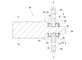
- FIG. 7 is a perspective view of a preliminary assembly configured when assembling the reverse input cutoff clutch.
- FIG. 8 is a cross-sectional view of the pre-assembly.
- FIG. 9 is an enlarged cross-sectional view of the main part of the reverse input cut-off clutch for explaining why it is preferable to provide a chamfered portion on the spacer on the side of the output member.
- FIG. 10 is an exploded perspective view showing the pre-assembly.
- FIG. 11 is a cross-sectional view of an output side assembly that is configured when assembling the reverse input cutoff clutch.
- FIG. 12 is a cross-sectional view of an input-side assembly configured when assembling the reverse input cutoff clutch.
- FIG. 13 is a cross-sectional view showing a reverse input cut-off clutch according to a comparative example of the present disclosure
- FIG. 14 is an exploded perspective view showing a reverse input cutoff clutch according to the comparative example
- FIG. 15 is a cross-sectional view showing a pair of engaging elements, an input member, a pair of plate springs, and an input-side radial rolling bearing that constitute the reverse input interrupting clutch according to the comparative example.
- the axial direction, radial direction, and circumferential direction refer to the axial direction, radial direction, and circumferential direction of the reverse input cut-off clutch 1 unless otherwise specified.
- the axial direction, radial direction, and circumferential direction of the reverse input cut-off clutch 1 coincide with the axial direction, radial direction, and circumferential direction of the input member 3, and the axial direction, radial direction, and circumferential direction of the output member 4. and circumferential direction.
- one side in the axial direction refers to the side of the input member 3 (right side in FIG. 1), and the other side in the axial direction refers to the side of the output member 4 (left side in FIG. 1).
- a reverse input interrupting clutch 1 of this example includes a pressed member 2 , an input member 3 , an output member 4 , an engaging element 5 and an elastic member 6 .
- the reverse input cut-off clutch 1 transmits the rotational torque input to the input member 3 to the output member 4, while completely blocking the rotational torque reversely input to the output member 4 and transmitting it to the input member 3.
- it has a reverse input blocking function of transmitting only a part of the rotational torque reversely input to the output member 4 to the input member 3 and blocking the rest.
- materials of the input member, the output member, the pressed member, and the engaging member are not particularly limited.
- materials of these materials in addition to metals such as iron alloys, copper alloys, and aluminum alloys, synthetic resins mixed with reinforcing fibers can be applied as necessary.
- the input member, the output member, the pressed member, and the engaging element can be made of the same material, or can be made of different materials.
- the pressed member 2 is supported and fixed to a fixed portion and does not rotate even when the reverse input cutoff clutch 1 is used. Further, the pressed member 2 has a pressed surface 7 which is a cylindrical concave surface on the inner peripheral surface of the axially intermediate portion. In this example, the pressed member 2 comprises an input-side housing element 8 and an output-side housing element 9 .
- the output-side housing element 9 has a stepped cylindrical inner peripheral surface.
- the inner peripheral surface of the output-side housing element 9 connects the small-diameter cylindrical surface portion 10 on the other side in the axial direction, the large-diameter cylindrical surface portion 11 on the one side in the axial direction, the small-diameter cylindrical surface portion 10 and the large-diameter cylindrical surface portion 11, and and a connecting surface portion 12 directed to one side in the axial direction.
- the large-diameter cylindrical surface portion 11 constitutes the pressed surface 7 .
- the output-side housing element 9 has an inward flange portion 13 protruding radially inward at the other end in the axial direction of the small-diameter cylindrical surface portion 10 , and a cylindrical inner diameter on the outer peripheral surface of one end in the axial direction. It has a side fitting surface portion 14 .
- the input-side housing element 8 includes a hollow circular plate-shaped side plate portion 15, a large-diameter cylindrical portion 16 bent over the entire circumference from the radially outer end portion of the side plate portion 15 toward the other side in the axial direction, and the side plate portion. 15, and a small-diameter cylindrical portion 17 protruding from the radially intermediate portion 15 toward one side in the axial direction over the entire circumference.
- the large-diameter cylindrical portion 16 has an outer diameter side fitting surface portion 18 on its inner peripheral surface.
- the inner diameter side fitting surface portion 14 of the output side housing element 9 and the outer diameter side fitting surface portion 18 of the input side housing element 8 are mated by spigot fitting without looseness, whereby the input side The housing element 8 and the output housing element 9 are radially positioned.
- the input-side housing element 8 and the output-side housing element 9 are connected to each other by a connecting member such as a bolt (not shown). together constitute the member to be pressed 2 .
- the pressed member 2 is attached to the fixed portion by screwing a bolt inserted through a through hole provided in the fixed portion into a screw hole 19 opening on the other axial side of the output-side housing element 9 . supported and fixed.
- the input member 3 is connected to an input-side mechanism such as an electric motor, and receives rotational torque.
- the input member 3 has an input shaft portion 20 , an input flange portion 21 and an input side engaging portion 22 .
- the input shaft portion 20 has a cylindrical shape.
- the input flange portion 21 protrudes radially outward over the entire circumference from the outer peripheral surface of the end portion on the other axial side of the input shaft portion 20 .
- the input-side engaging portions 22 protrude toward the other side in the axial direction from two positions on the other side in the axial direction of the input flange portion 21 on the opposite side in the radial direction.
- the number of input-side engaging portions 22 corresponds to the number of engaging elements 5 .
- a pair (two pieces) of input-side engaging portions 22 are provided, and these input-side engaging portions 22 are separated from each other in the radial direction of the input member 3 .
- the pair of input-side engaging portions 22 are arranged on the other side surface in the axial direction of the input flange portion 21 at a portion radially outwardly deviated from the rotation center O of the input member 3 .
- the pair of input-side engaging portions 22 has end faces that are generally fan-shaped when viewed from the axial direction and that are symmetrical with respect to the circumferential direction.
- the radial inner side surfaces 23 of the pair of input side engaging portions 22 are configured by flat surfaces parallel to each other, and the radial outer side surfaces 24 of the respective input side engaging portions 22 are , has the same cylindrical contour shape as the outer peripheral surface of the input flange portion 21 .
- a pair of circumferential side surfaces 25 of each of the input-side engaging portions 22 are formed of flat surfaces that are inclined in directions away from each other toward the radially outer side.
- the input member 3 is rotatably supported inside the input side housing element 8 of the pressed member 2 by the input side radial rolling bearing 26 .
- the outer ring 27 of the input-side radial rolling bearing 26 is fitted inside the small-diameter cylindrical portion 17 of the input-side housing element 8 without looseness, and the radially inner portion of one axial side surface of the side plate portion 15 and the small-diameter cylindrical portion 17 and a retaining ring 30a that is engaged with one axial side portion of 17.
- the inner ring 28 of the input-side radial rolling bearing 26 is fitted onto the other end of the input shaft portion 20 of the input member 3 in the axial direction without looseness, and the input flange portion It is axially sandwiched between a snap ring 30b and a retaining ring 30b that is engaged with the outer peripheral surface of the axially intermediate portion of the shaft portion 20. As shown in FIG.
- the input-side radial rolling bearing 26 is composed of a ball bearing using balls as the rolling elements 29 .
- the input-side radial rolling bearing for supporting the input member 3 may be composed of a tapered roller bearing using tapered rollers or a roller bearing using cylindrical rollers as rolling elements.
- the pair of input-side engaging portions 22 are arranged radially inside the pressed surface 7 .
- the output member 4 is connected to an output-side mechanism such as a speed reduction mechanism, and outputs rotational torque.
- the output member 4 is arranged coaxially with the input member 3 .
- the output member 4 has an output shaft portion 31 , an output flange portion 32 , an output side engaging portion 33 and a small diameter shaft portion 34 .
- the output shaft portion 31 has a cylindrical shape.
- the output flange portion 32 protrudes radially outward over the entire circumference from the outer peripheral surface of one end of the output shaft portion 31 in the axial direction.
- the output side engaging portion 33 protrudes from the central portion of one side surface of the output flange portion 32 in the axial direction toward one side in the axial direction.
- the output side engaging portion 33 has a cam function. That is, the distance from the rotation center O of the output member 4 to the outer peripheral surface of the output side engaging portion 33 is not constant in the circumferential direction.
- the output side engaging portion 33 has a substantially rectangular end face shape when viewed from the axial direction. That is, the outer peripheral surface of the output side engaging portion 33 is composed of a pair of long side portions 38 and a pair of short side portions 39 .
- the output-side engaging portion 33 is symmetrical with respect to a virtual plane that passes through the rotation center O of the output member 4 and is perpendicular to the pair of long side portions 38, and is symmetrical with respect to the rotation center O of the output member 4. symmetrical with respect to an imaginary plane parallel to the pair of long sides 38 .
- the pair of short side portions 39 are present on the same cylindrical surface as the outer peripheral surface of the output flange portion 32 .
- the small-diameter shaft portion 34 has a cylindrical shape and protrudes from the central portion of one axial side surface of the output flange portion 32 toward one axial side.
- the axial length of the small-diameter shaft portion 34 is greater than the axial length of the output side engaging portion 33 . That is, the tip portion (one axial end) of the small-diameter shaft portion 34 protrudes to one axial side from the tip surface (one axial end surface) of the output-side engaging portion 33 .
- the outer diameter dimension of the small diameter shaft portion 34 is larger than the interval between the pair of long side portions 38 of the output side engaging portion 33 . That is, the radially outer portion of the small-diameter shaft portion 34 protrudes radially outward from the lengthwise intermediate portion of the long side portion 38 .
- the output shaft portion 31 of the output member 4 is rotatably supported inside the output side housing element 9 by the output side radial rolling bearing 40 .
- the outer ring 41 of the output-side radial rolling bearing 40 is fitted inside the small-diameter cylindrical surface portion 10 of the output-side housing element 9 without rattling. It is sandwiched in the axial direction with a retaining ring 44a locked at one end.
- the inner ring 42 of the output-side radial rolling bearing 40 is fitted onto the output shaft portion 31 without backlash, and engages with the other axial side surface of the output flange portion 32 and the outer peripheral surface of the axially intermediate portion of the output shaft portion 31 . It is axially sandwiched between it and the stopped retaining ring 44b.
- the output-side radial rolling bearing 40 is composed of a ball bearing using balls as the rolling elements 43 .
- the radial rolling bearing for supporting the output member 4 may be composed of a tapered roller bearing using tapered rollers or a roller bearing using cylindrical rollers as rolling elements.
- the small diameter shaft portion 34 of the output member 4 is inserted inside the input member 3 .
- a radial bearing such as a sliding bearing may be arranged between the outer peripheral surface of the small diameter shaft portion 34 and the inner peripheral surface of the input member 3 .
- a locking groove 59 is formed along the entire circumference of the outer peripheral surface of the axially intermediate portion of the small-diameter shaft portion 34 .
- the output side engaging portion 33 is arranged between the pair of input side engaging portions 22 while the output member 4 is rotatably supported inside the pressed member 2 .
- the engaging element 5 has a pressing surface 45 facing the pressed surface 7 , an input side engaged portion 50 that can be engaged with the input side engaging portion 22 , and an output side that can be engaged with the output side engaging portion 33 . and is disposed between the pressed surface 7 and the output-side engaging portion 33 in a first direction, which is a far-near direction with respect to the pressed surface 7, so as to be movable in the first direction.
- one pair (two pieces) of engaging elements 5 is provided.
- the pair of engaging elements 5 are arranged radially inwardly of the member to be pressed 2 with their pressing surfaces 45 directed to opposite sides in the radial direction and their radially inner surfaces facing each other. It is arranged to allow movement in one direction.
- the number of engaging elements is arbitrary, and the number of engaging elements can be one or three or more. In this case, the configurations of the input-side engaging portion and the output-side engaging portion can be appropriately changed according to the number of engaging elements.
- the radial direction of the engaging element 5 means the far-near direction with respect to the pressed surface 7 of the engaging element 5, that is, the first direction, indicated by the arrow ⁇ in FIG.
- the width direction of the engaging piece 5 means the direction perpendicular to the first direction, which is indicated by the arrow ⁇ in FIG.
- Each of the engaging elements 5 constituting the pair of engaging elements 5 has a pair of pressing surfaces 45 facing the pressed surface 7 at two circumferentially-separated positions on the radial outer surface,
- a substantially arc-shaped notch portion 46 is provided in the circumferential center portion between the pair of pressing surfaces 45 on the radial outer surface.
- Each pressing surface 45 is formed of a partially cylindrical convex curved surface having a radius of curvature smaller than the radius of curvature of the pressed surface 7 .
- a portion of the radial outer surface of the engaging element 5, which includes the notch 46 and is circumferentially deviated from the pair of pressing surfaces 45, is centered on the central axis O of the input member 3 when viewed in the axial direction. , and is located radially inward of the imaginary circle that is in contact with the pair of pressing surfaces 45 . That is, in a state in which the pair of pressing surfaces 45 are in contact with the pressed surface 7 , the portion of the radially outer side surface of the engaging element 5 that is circumferentially deviated from the pair of pressing surfaces 45 is the pressed surface 7 . do not come into contact with
- each pressing surface 45 has a surface texture that has a larger coefficient of friction with respect to the surface to be pressed 7 than the surface of other portions of the engaging element 5 .
- the pressing surface 45 can be configured integrally with the engaging element 5, or can be configured by a surface of a friction material fixed to the radially outer surface of the engaging element 5 by sticking, bonding, or the like. .
- the engaging element 5 includes a recess 47 having an arcuate cross-sectional shape in the widthwise central portion of the radially inner end portion, and has radially inner portions on both widthwise side portions sandwiching the recessed portion 47 .
- a pair of projecting protrusions 48 are provided.
- the engaging element 5 has a flat surface portion 49 extending in the width direction of the engaging element 5 when viewed from the axial direction on a portion other than the concave portion 47 and the pair of convex portions 48 formed on the radial inner surface.
- the flat surface portions 49 of the pair of engaging elements 5 are formed of flat surfaces parallel to each other.
- the inner surface of the concave portion 47 is formed of a cylindrical concave surface having a radius of curvature larger than the radius of curvature of the outer peripheral surface of the small-diameter shaft portion 34 of the output member 4 .
- portions of the flat surface portion 49 positioned on both sides of the recess 47 in the width direction engage with the output-side engaging portion 33 . That is, in this example, portions of the flat surface portion 49 positioned on both sides in the width direction of the recess 47 constitute output-side engaged portions.
- the engaging element 5 has an input-side engaged portion 50 that can be engaged with the input-side engaging portion 22 at the radially intermediate portion of the widthwise central portion.
- the input-side engaged portion 50 has a substantially arcuate opening shape when viewed from the axial direction, and a through hole axially penetrating through a radially intermediate portion of the engaging element 5 at the center position in the width direction. It is composed of
- the input-side engaged portion 50 has a size that allows the input-side engaging portion 22 to be loosely inserted. Therefore, when the input-side engaging portion 22 is inserted inside the input-side engaged portion 50 , the engaging element 5 is placed between the input-side engaging portion 22 and the inner surface of the input-side engaged portion 50 .
- the input side engaging portion 22 can be displaced in the rotational direction of the input member 3 with respect to the input side engaged portion 50 of the engaging element 5, and the input side engaged portion 50 can be displaced relative to the input side engaged portion 50.
- the engaging element 5 can be displaced in the radial direction with respect to the joining portion 22 .
- the input-side engaged portion 50 has a flat surface 51 parallel to the flat surface portion 49 on its radial inner surface (surface facing radially outward).
- the input-side engaged portion can also be configured by a bottomed hole that opens only on one axial side surface of the engaging element.
- the input-side engaged portion can be configured by a notch that opens to the radially outer surface of the engaging element.
- the pair of input-side engaging portions 22 of the input member 3 are in a state in which the pair of engaging elements 5 are arranged radially inside the pressed member 2 , and the pair of input-side engaging portions 22 of the pair of engaging elements 5 are engaged. 50 , and the output side engaging portion 33 of the output member 4 is arranged between the pair of flat surface portions 49 .
- the elastic member 6 suppresses rattling between the output-side engaging portion 33 of the output member 4 and the flat surface portion 49 constituting the output-side engaged portion of the engaging element 5.
- the pair of pressing surfaces 45 is elastically biased in the direction to approach the pressed surface 7 .
- an elastic member 6 is arranged in each of the engaging elements 5 that constitute a pair of engaging elements 5 .
- the elastic member 6 is arranged between the output side engaging portion 33 of the output member 4 and the flat surface portion 49 of the engaging element 5 .
- the number of elastic members 6 can be changed according to the number of engaging elements 5 . That is, the pair of engaging elements 5, the pair of (two) elastic members 6, and the output-side engaging portion 33 are configured such that the flat surface portion 49 and the pair of elastic members 6 are positioned radially outwardly of the output-side engaging portion 33. are placed so as to be sandwiched between
- the elastic member 6 is composed of a leaf spring.
- the elastic member 6 can also be made of a coil spring, a disc spring, or an elastic material such as rubber, elastomer, or resin.
- the elastic member 6 has a pair of arm portions 52 and a pair of connecting portions 53, as shown in FIG.
- the pair of arm portions 52 has a substantially H-shaped planar shape when viewed from the plate thickness direction (radial direction of the engaging element 5).
- each of the arm portions 52 includes a pair of rectangular plate-like width direction plate pieces 52a that are separated from each other in the axial direction and extend in the width direction of the engaging element 5, and the pair of width direction plate pieces 52a. It has an axial direction plate piece 52b that connects intermediate portions in the extension direction of the direction plate pieces 52a. That is, each arm portion 52 has a notch 52c that opens at the tip portion (outer end portion in the width direction of the engaging element 5).
- each connecting portion 53 has a substantially U-shaped or substantially V-shaped end surface shape when viewed from the axial direction.
- the shape of the connecting portion is not particularly limited as long as interference with the input member and the output member can be prevented.
- the connecting portion can also be configured in a flat plate shape.
- the pair of elastic members 6 lock the notches 52c formed in the pair of arms 52 to the pair of projections 48 of the respective engaging elements 5.
- the pair of protrusions 48 of the engaging piece 5 are arranged inside the cutouts 52c of the pair of arm portions 52 of the elastic member 6 .
- the elastic member 6 is supported with respect to the engaging element 5 so as to be displaceable relative to each other in the axial and width directions, but to be displaceable relative to each other in the radial direction (first direction).
- each engaging element 5 and the output side engaging portion 33 specifically, the radial position of each engaging element 5 and the rotation of the output side engaging portion 33 with respect to each engaging element 5
- the output-side engaging portion 33 is elastically brought into contact with the pair of elastic members 6 regardless of the phase. This suppresses looseness between the output side engaging portion 33 and the output side engaged portion.
- Both axial side portions of the pair of arm portions 52 of each elastic member 6 protrude axially beyond both axial side surfaces of the engaging element 5 .
- the reverse input cutoff clutch 1 of this example includes a pair of spacers 54 .
- Each spacer 54 constituting the pair of spacers 54 has a flat plate shape, has a substantially oval or substantially rectangular end face shape when viewed from the axial direction, and has an output-side engaging portion 33 and a small-diameter shaft portion 34. It has a through hole 55 through which it can be inserted without rattling.
- the pair of spacers 54 are arranged on both sides of the pair of elastic members 6 in the axial direction with the output-side engaging portion 33 and the small-diameter shaft portion 34 inserted through the respective through holes 55 without play.
- the pair of spacers 54 of the pair of elastic members 6 , axially opposite end faces formed by the fractured surfaces and the sheared surfaces are aligned with the other axial side surface of the input flange portion 21 of the input member 3 and the output member 4 . This prevents contact with one side surface of the output flange portion 32 in the axial direction.
- the pair of spacers 54 sandwich the pair of elastic members 6 in the axial direction, and extend the spacer 54 to a position facing the pair of arm portions 52 of the elastic member 6 so that the pair of arm portions 52 The rattling of the engaging element 5 is suppressed by restricting the rattling in the axial direction.
- the pair of spacers 54 oppose the pair of arms 52 of the elastic member 6 to regulate the axial displacement of the engaging element 5. It is also possible to restrict the axial displacement of the engaging element by facing the .
- the spacer 54 on the other side in the axial direction of the pair of spacers 54 preferably has a chamfered portion 56 on the opening edge of the through hole 55 on the other side in the axial direction.
- the chamfered portion 56 is formed by C-chamfering having a linear cross-sectional shape. Further, the chamfering depth of the chamfering portion 56 is set to be equal to or greater than the chamfering radius of the corner R portion 57 connecting one axial side surface of the output flange portion 32 and the long side portion 38 of the output side engaging portion 33 . The presence of the chamfered portion 56 effectively prevents interference between the corner R portion 57 and the opening edge on the other axial side of the through hole 55 provided in the spacer 54 on the other axial side.
- the reverse input cutoff clutch 1 of this example includes a stopper member 58 .
- the stopper member 58 is configured by a retaining ring having a partially annular shape. That is, the stopper member 58 has a substantially C-shaped end face shape when viewed from the axial direction.
- the stopper member may also be configured by a speed nut or bush nut that is hollow circular plate-shaped and has radial slits formed in its radially inner portion.
- the stopper member 58 is locked in a locking groove 59 provided in the outer peripheral surface of the axially intermediate portion of the small-diameter shaft portion 34, and via the spacer 54 on one side in the axial direction and the pair of elastic members 6, It opposes one side surface of the pair of engaging elements 5 in the axial direction.
- the pair of elastic members 6 supported by the pair of engaging elements 5 so as not to be relatively displaceable in the axial direction and the width direction are attached to the axial ends of the output flange portion 32 via the pair of spacers 54. It is sandwiched between the side surface and the stopper member 58 in the axial direction. This prevents axial relative displacement of the pair of engaging elements 5 with respect to the output member 4 . That is, the stopper member 58 constitutes displacement prevention means.
- the spacer locks to the output member and is attached directly to the axial side of the engager or to another member such as a resilient member. can also be opposed via That is, the spacer can be provided with a function as a stopper member.
- the stopper member 58 is opposed to one side surface of the engaging element 5 in the axial direction via the spacer 54 and the elastic member 6 . It can also be directly opposed to one side.
- a crimped portion or the like formed on the output member may constitute a displacement prevention means for preventing relative displacement of the engaging element in the axial direction with respect to the output member.
- the input side engaging portion 22 rotates inside the input side engaged portion 50 in the direction of rotation of the input member 3 (in the example of FIG. 4, in the opposite direction). clockwise). Then, the radially inner side surface 23 of the input-side engaging portion 22 presses the flat surface 51 of the input-side engaged portion 50 radially inward, moving the engaging element 5 away from the pressed surface 7 . Let That is, the engaging element 5 is moved radially inward based on the engagement with the input member 3 . In this example, by engaging the pair of input-side engaging portions 22 and the pair of engaging elements 5, the engaging elements 5 positioned on the upper side in FIG. The engaging elements 5 to be engaged are moved upward.
- the engaging element 5 moves radially inward, and the flat surface portion 49 constituting the output side engaging portion of the engaging element 5 engages with the output side engaging portion 33 of the output member 4 .
- the radial inner surfaces of the pair of engaging elements 5 move toward each other, and the flat surface portions 49 of the pair of engaging elements 5 clamp the output side engaging portion 33 of the output member 4 from both radial directions. do.
- the output member 4 and the long side portion 38 of the output-side engaging portion 33 engage with the flat surface portion 49 of the engaging element 5 .
- the output side engaging portion 33 rotates in the rotational direction of the output member 4 (clockwise in the example of FIG. 4). Then, of the outer peripheral surface of the output side engaging portion 33, the connection portion (corner portion) between the long side portion 38 and the short side portion 39 forms the flat surface portion 49 constituting the output side engaged portion of the engaging element 5. , presses radially outward, and moves the engaging element 5 in a direction toward the pressed surface 7, that is, radially outward. As a result, the pressing surface 45 of the engaging element 5 is frictionally engaged with the pressed surface 7 .
- the engagement between the output side engaging portion 33 of the output member 4 and the flat surface portion 49 of the pair of engaging elements 5 causes the pair of engaging elements 5 to move away from each other, that is, upward in FIG.
- the engaging element 5 positioned on the upper side and the engaging element 5 positioned on the lower side in FIG. 7 are frictionally engaged.
- the rotational torque reversely input to the output member 4 is completely cut off and is not transmitted to the input member 3, or only a part of the rotational torque reversely input to the output member 4 is transmitted to the input member 3. The remainder is blocked.
- the pressing surface 45 of the engaging element 5 does not slide (relatively rotate) with respect to the pressed surface 7. , the engaging element 5 is stretched between the output-side engaging portion 33 and the pressed member 2 to lock the output member 4 .
- the pressing surface 45 should be The output member 4 is semi-locked by stretching the engaging element 5 between the output-side engaging portion 33 and the pressed member 2 so as to be slidable.
- the sizes of the gaps between the constituent members are adjusted so that the above operations are possible.
- the pressing surface 45 of the engaging element 5 in contact with the pressed surface 7 , there is an output side contact between the radial inner surface 23 of the input side engaging portion 22 and the inner surface of the input side engaged portion 50 .
- the surface pressure acting on the contact portion between the pressing surface 45 and the pressed surface 7 is changed according to the magnitude of the rotational torque reversely input to the output member 4. , the output member 4 is properly locked or semi-locked.
- the reverse input cut-off clutch 1 of this example can be assembled, for example, as follows.
- the output side engaging portion 33 and the small diameter shaft portion 34 of the output member 4 are inserted through the through holes 55 of the pair of spacers 54 .
- the elastic member 6 is supported by the engaging element 5 by engaging the notches 52 c of the elastic member 6 with the pair of protrusions 48 of the engaging element 5 .
- the pair of engaging elements 5 are arranged so that the output-side engaging portion 33 of the output member 4 is sandwiched from the radially outer side by the respective flat surface portions 49 and the pair of elastic members 6 .
- the stopper member 58 is locked in the locking groove 59 of the output member 4 .
- a pre-assembly 60 as shown in FIGS. 7 and 8 is obtained.
- the inner ring 42 of the output side radial rolling bearing 40 is fitted onto the output shaft portion 31 of the output member 4 without backlash, and the snap ring 44b is locked to the outer peripheral surface of the axially intermediate portion of the output shaft portion 31 .
- the output member 4 is inserted inside the output-side housing element 9 from one side in the axial direction.
- an assembly jig (not shown) is used to push the pair of engaging elements 5 toward each other against the elastic force of the pair of elastic members 6. Displaced (toward radially inward). After the end surface on the other axial side of the outer ring 41 of the output-side radial rolling bearing 40 abuts against one side surface of the inward flange portion 13 in the axial direction, the assembly jig is retracted, and the pair of engaging elements 5 are engaged.
- the procedure for assembling the output side assembly 61 can be changed in order or performed simultaneously as long as there is no contradiction.
- an input side assembly 62 as shown in FIG. 12 is obtained.
- the output side assembly 61 is and the input side assembly 62 are displaced toward each other in the axial direction.
- the inner diameter side fitting surface portion 14 of the output side housing element 9 and the outer diameter side fitting surface portion 18 of the input side housing element 8 are fitted without rattling, and the pair of input side engaging portions 22 are fitted together.
- the input-side housing element 8 and the output-side housing element 9 are connected to each other by a connecting member to assemble the reverse input cut-off clutch 1 .
- the stopper member 58 prevents the pair of engaging elements 5 from axially displacing relative to the output member 4 . Therefore, as shown in FIG. 11, the output member 4, the pair of engaging elements 5, and the output-side housing element 9 can be sub-assembled as an output-side assembly 61. As shown in FIG. By displacing the output side assembly 61 and the input side assembly 62 toward each other in the axial direction, the inner diameter side fitting surface portion 14 and the outer diameter side fitting surface portion 18 are fitted without play. At the same time, the pair of input side engaging portions 22 of the input member 3 are inserted into the input side engaged portions 50 of the pair of engaging elements 5 to form the output side assembly 61 and the input side assembly 62. are combined.
- ⁇ Comparative example> 13-15 show a comparative reverse input disconnect clutch with respect to the present disclosure.
- the reverse input interrupt clutch 100 of the comparative example does not have a pair of spacers 54, a stopper member 58, and a structure for attaching them to the reverse input interrupt clutch 100. It is the same as the reverse input cutoff clutch 1 of one example of the form of .
- the output shaft portion 111 of the output member 110 is rotatably supported inside the output side housing element 113 constituting the pressed member 108 by the output side radial rolling bearing 112 .
- the output member 110, the output radial rolling bearing 112 and the output housing element 113 are combined to obtain the output assembly.
- the input-side assembly and the output-side assembly are brought closer to each other in the axial direction, and the output-side engaging portion 114 of the output member 110 is positioned radially inside the pair of engaging elements 101 . It is inserted between the pair of leaf springs 105 .
- the pair of engaging elements 101 are arranged inside the pressed surface 115 provided on the inner peripheral surface of the output-side housing element 113, and the pressing force provided on the radially outer side surface of the pair of engaging elements 101 is arranged.
- the surface 116 is opposed to the pressed surface 115 .
- the input-side housing element 109 and the output-side housing element 113 are coupled and fixed to form the member 108 to be pressed, thereby obtaining the reverse input cutoff clutch 100 .
- a pair of leaf springs 105 are elastically sandwiched between the output-side engaged portion 117 and the output-side engaging portion 114, but each leaf spring 105 falls off from either member. not impossibly supported. Therefore, before the output-side engaging portion 114 is inserted between the pair of leaf springs 105, the leaf springs 105 move toward each other, and the gap between the pair of leaf springs 105 becomes It may be narrow. From this point of view as well, the operation of inserting the output-side engaging portion 114 of the output member 110 between the pair of leaf springs 105 may be troublesome.
- the pair of input-side engaging portions 22 are connected to the input-side engaged portion. It can be loosely inserted into the engaging portion 50 . That is, according to the reverse input interrupting clutch 1 of the present embodiment, the pair of leaf springs 105 are arranged while increasing the distance between the pair of leaf springs 105 as in the method of assembling the reverse input interrupting clutch 100 of the comparative example. There is no need to insert the output-side engaging portion 114 between. Therefore, in the reverse input cut-off clutch 1 of this example, the assembling work can be facilitated, and the ease of assembly can be improved.
- the pair of engaging elements 101 are axially displaceable by several millimeters with respect to the input member 103 and the output member 110 . Therefore, there is a possibility that the engaging element 101 falls down in the axial direction.
- the engaging element 101 moves radially outward while the engaging element 101 is tilted in the axial direction, the pressing surface 116 and the pressed surface 115 are locally abutted and bite into each other, and the locked or semi-locked state is changed. There is a possibility that the force required for switching to the unlocked state or the semi-unlocked state will increase unnecessarily, or plastic deformation will occur in the pressing surface 116 and/or the pressed surface 115 .
- the stopper member 58 prevents the pair of engaging elements 5 from moving relative to the output member 4 in the axial direction. You can prevent it from falling over. Therefore, the switching operation between the locked or semi-locked state and the unlocked or semi-unlocked state of the output member 4 can be stably performed.
Landscapes
- Engineering & Computer Science (AREA)
- General Engineering & Computer Science (AREA)
- Mechanical Engineering (AREA)
- Braking Arrangements (AREA)
Priority Applications (4)
| Application Number | Priority Date | Filing Date | Title |
|---|---|---|---|
| CN202280029761.2A CN117242274A (zh) | 2022-01-14 | 2022-12-27 | 反向输入阻断离合器及其组装方法 |
| JP2023542824A JP7375991B1 (ja) | 2022-01-14 | 2022-12-27 | 逆入力遮断クラッチおよびその組立方法 |
| US18/287,951 US12259015B2 (en) | 2022-01-14 | 2022-12-27 | Reverse-input blocking clutch and manufacturing method thereof |
| EP22920665.1A EP4310357A4 (en) | 2022-01-14 | 2022-12-27 | REVERSE INPUT CUT-OFF CLUTCH AND ITS ASSEMBLY METHOD |
Applications Claiming Priority (2)
| Application Number | Priority Date | Filing Date | Title |
|---|---|---|---|
| JP2022-004648 | 2022-01-14 | ||
| JP2022004648 | 2022-01-14 |
Publications (1)
| Publication Number | Publication Date |
|---|---|
| WO2023136149A1 true WO2023136149A1 (ja) | 2023-07-20 |
Family
ID=87279121
Family Applications (1)
| Application Number | Title | Priority Date | Filing Date |
|---|---|---|---|
| PCT/JP2022/048382 Ceased WO2023136149A1 (ja) | 2022-01-14 | 2022-12-27 | 逆入力遮断クラッチおよびその組立方法 |
Country Status (5)
| Country | Link |
|---|---|
| US (1) | US12259015B2 (https=) |
| EP (1) | EP4310357A4 (https=) |
| JP (1) | JP7375991B1 (https=) |
| CN (1) | CN117242274A (https=) |
| WO (1) | WO2023136149A1 (https=) |
Citations (3)
| Publication number | Priority date | Publication date | Assignee | Title |
|---|---|---|---|---|
| JP2019138410A (ja) * | 2018-02-14 | 2019-08-22 | 日本精工株式会社 | 逆入力遮断クラッチ |
| WO2019216280A1 (ja) * | 2018-05-07 | 2019-11-14 | 日本精工株式会社 | 逆入力遮断クラッチ及びアクチュエータ |
| WO2021107073A1 (ja) | 2019-11-29 | 2021-06-03 | 日本精工株式会社 | 逆入力遮断クラッチ |
Family Cites Families (3)
| Publication number | Priority date | Publication date | Assignee | Title |
|---|---|---|---|---|
| US1617745A (en) * | 1927-02-15 | Albert cotysinard | ||
| US3051282A (en) * | 1959-12-15 | 1962-08-28 | Whitney E Greene | Self-locking rotary transmission |
| CN110998119A (zh) * | 2017-08-01 | 2020-04-10 | 日本精工株式会社 | 逆向输入断开离合器、电动配气正时调整装置、可变压缩比装置及电动助力转向装置 |
-
2022
- 2022-12-27 WO PCT/JP2022/048382 patent/WO2023136149A1/ja not_active Ceased
- 2022-12-27 US US18/287,951 patent/US12259015B2/en active Active
- 2022-12-27 EP EP22920665.1A patent/EP4310357A4/en active Pending
- 2022-12-27 CN CN202280029761.2A patent/CN117242274A/zh active Pending
- 2022-12-27 JP JP2023542824A patent/JP7375991B1/ja active Active
Patent Citations (3)
| Publication number | Priority date | Publication date | Assignee | Title |
|---|---|---|---|---|
| JP2019138410A (ja) * | 2018-02-14 | 2019-08-22 | 日本精工株式会社 | 逆入力遮断クラッチ |
| WO2019216280A1 (ja) * | 2018-05-07 | 2019-11-14 | 日本精工株式会社 | 逆入力遮断クラッチ及びアクチュエータ |
| WO2021107073A1 (ja) | 2019-11-29 | 2021-06-03 | 日本精工株式会社 | 逆入力遮断クラッチ |
Non-Patent Citations (1)
| Title |
|---|
| See also references of EP4310357A4 |
Also Published As
| Publication number | Publication date |
|---|---|
| US12259015B2 (en) | 2025-03-25 |
| CN117242274A (zh) | 2023-12-15 |
| EP4310357A1 (en) | 2024-01-24 |
| US20240200617A1 (en) | 2024-06-20 |
| EP4310357A4 (en) | 2024-10-16 |
| JP7375991B1 (ja) | 2023-11-08 |
| JPWO2023136149A1 (https=) | 2023-07-20 |
Similar Documents
| Publication | Publication Date | Title |
|---|---|---|
| CN112703331B (zh) | 带反向输入切断离合器的电动马达 | |
| CN113767229B (zh) | 反向输入切断离合器 | |
| JP7501796B2 (ja) | 逆入力遮断クラッチ | |
| US11708870B2 (en) | Reverse-input blocking clutch | |
| JP7327712B1 (ja) | 逆入力遮断クラッチ | |
| EP3748186B1 (en) | Clutch unit | |
| US20260110343A1 (en) | Reverse-input blocking clutch | |
| WO2021152980A1 (ja) | 逆入力遮断クラッチ | |
| US11629768B2 (en) | Reverse input cutoff clutch | |
| WO2023136149A1 (ja) | 逆入力遮断クラッチおよびその組立方法 | |
| JP7017190B2 (ja) | 逆入力遮断クラッチ | |
| JP7188177B2 (ja) | 逆入力遮断クラッチ | |
| JP7831719B1 (ja) | 逆入力遮断クラッチ | |
| JP2023085990A (ja) | 逆入力遮断クラッチ | |
| JP2023018310A (ja) | 逆入力遮断クラッチ及びこれを備えるクラッチユニット | |
| WO2024247372A1 (ja) | 逆入力遮断クラッチ | |
| JP7375989B1 (ja) | 逆入力遮断クラッチ | |
| JP2023022882A (ja) | 逆入力遮断クラッチ | |
| JP2024112433A (ja) | 逆入力遮断クラッチ | |
| WO2023233801A1 (ja) | 逆入力遮断クラッチ | |
| JP2023175529A (ja) | 逆入力遮断クラッチ | |
| WO2025018179A1 (ja) | 逆入力遮断クラッチおよびその組立方法 | |
| JP2025125461A (ja) | 逆入力遮断クラッチ | |
| JP2026005996A (ja) | 逆入力遮断クラッチ | |
| JP2024089052A (ja) | 逆入力遮断クラッチ |
Legal Events
| Date | Code | Title | Description |
|---|---|---|---|
| WWE | Wipo information: entry into national phase |
Ref document number: 2023542824 Country of ref document: JP |
|
| 121 | Ep: the epo has been informed by wipo that ep was designated in this application |
Ref document number: 22920665 Country of ref document: EP Kind code of ref document: A1 |
|
| WWE | Wipo information: entry into national phase |
Ref document number: 2022920665 Country of ref document: EP |
|
| WWE | Wipo information: entry into national phase |
Ref document number: 202280029761.2 Country of ref document: CN |
|
| WWE | Wipo information: entry into national phase |
Ref document number: 18287951 Country of ref document: US |
|
| ENP | Entry into the national phase |
Ref document number: 2022920665 Country of ref document: EP Effective date: 20231016 |
|
| NENP | Non-entry into the national phase |
Ref country code: DE |
|
| WWG | Wipo information: grant in national office |
Ref document number: 18287951 Country of ref document: US |