WO2023135751A1 - 切削液供給装置 - Google Patents
切削液供給装置 Download PDFInfo
- Publication number
- WO2023135751A1 WO2023135751A1 PCT/JP2022/001152 JP2022001152W WO2023135751A1 WO 2023135751 A1 WO2023135751 A1 WO 2023135751A1 JP 2022001152 W JP2022001152 W JP 2022001152W WO 2023135751 A1 WO2023135751 A1 WO 2023135751A1
- Authority
- WO
- WIPO (PCT)
- Prior art keywords
- cutting fluid
- tank
- supply device
- fluid supply
- nozzle
- Prior art date
- Legal status (The legal status is an assumption and is not a legal conclusion. Google has not performed a legal analysis and makes no representation as to the accuracy of the status listed.)
- Ceased
Links
Images

Classifications
-
- B—PERFORMING OPERATIONS; TRANSPORTING
- B23—MACHINE TOOLS; METAL-WORKING NOT OTHERWISE PROVIDED FOR
- B23Q—DETAILS, COMPONENTS, OR ACCESSORIES FOR MACHINE TOOLS, e.g. ARRANGEMENTS FOR COPYING OR CONTROLLING; MACHINE TOOLS IN GENERAL CHARACTERISED BY THE CONSTRUCTION OF PARTICULAR DETAILS OR COMPONENTS; COMBINATIONS OR ASSOCIATIONS OF METAL-WORKING MACHINES, NOT DIRECTED TO A PARTICULAR RESULT
- B23Q11/00—Accessories fitted to machine tools for keeping tools or parts of the machine in good working condition or for cooling work; Safety devices specially combined with or arranged in, or specially adapted for use in connection with, machine tools
-
- B—PERFORMING OPERATIONS; TRANSPORTING
- B23—MACHINE TOOLS; METAL-WORKING NOT OTHERWISE PROVIDED FOR
- B23Q—DETAILS, COMPONENTS, OR ACCESSORIES FOR MACHINE TOOLS, e.g. ARRANGEMENTS FOR COPYING OR CONTROLLING; MACHINE TOOLS IN GENERAL CHARACTERISED BY THE CONSTRUCTION OF PARTICULAR DETAILS OR COMPONENTS; COMBINATIONS OR ASSOCIATIONS OF METAL-WORKING MACHINES, NOT DIRECTED TO A PARTICULAR RESULT
- B23Q11/00—Accessories fitted to machine tools for keeping tools or parts of the machine in good working condition or for cooling work; Safety devices specially combined with or arranged in, or specially adapted for use in connection with, machine tools
- B23Q11/10—Arrangements for cooling or lubricating tools or work
-
- Y—GENERAL TAGGING OF NEW TECHNOLOGICAL DEVELOPMENTS; GENERAL TAGGING OF CROSS-SECTIONAL TECHNOLOGIES SPANNING OVER SEVERAL SECTIONS OF THE IPC; TECHNICAL SUBJECTS COVERED BY FORMER USPC CROSS-REFERENCE ART COLLECTIONS [XRACs] AND DIGESTS
- Y02—TECHNOLOGIES OR APPLICATIONS FOR MITIGATION OR ADAPTATION AGAINST CLIMATE CHANGE
- Y02P—CLIMATE CHANGE MITIGATION TECHNOLOGIES IN THE PRODUCTION OR PROCESSING OF GOODS
- Y02P70/00—Climate change mitigation technologies in the production process for final industrial or consumer products
- Y02P70/10—Greenhouse gas [GHG] capture, material saving, heat recovery or other energy efficient measures, e.g. motor control, characterised by manufacturing processes, e.g. for rolling metal or metal working
Definitions
- the present invention relates to a cutting fluid supply device.
- a cutting oil supply device disclosed in Japanese Utility Model Laid-Open No. 58-51941 supplies cutting oil to a cutting tool from a nozzle using a pump, and discharges chips with the cutting oil.
- the pump is a heat source, the pump changes the temperature of the cutting fluid. Therefore, in the cutting oil supply device disclosed in Japanese Utility Model Laid-Open No. 58-51941, the temperature change of the cutting fluid supplied from the nozzle changes the shape of the cutting tool or the object to be machined, resulting in a decrease in machining accuracy. I have a problem.
- An object of the present invention is to solve the above-mentioned problems.
- An aspect of the present invention is a cutting fluid supply device that discharges cutting fluid from a nozzle provided within a temperature-controlled machining area of a machine tool, comprising a tank that is provided within the machining area and stores the cutting fluid. a receiver provided in the machining area for collecting the discharged cutting fluid and flowing it to the tank; and a pump for supplying the cutting fluid stored in the tank to the nozzle.
- FIG. 1 is a diagram showing the configuration of a cutting fluid supply device and a machine tool according to one embodiment.
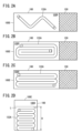
- 2A, 2B, 2C and 2D are diagrams illustrating how a portion of the second pipe arranged in the storage space of the tank is bent at a plurality of positions.
- FIG. 1 is a diagram showing the configuration of a cutting fluid supply device 10 and a machine tool 20 according to one embodiment.
- Machine tool 20 has a body 22 and a cutting tool 24 attached to body 22 .
- the machine tool 20 uses a cutting tool 24 to cut a workpiece (not shown). During cutting, chips are generated from the workpiece. This chip is generated from the location machined by the cutting tool 24 .
- a cutting fluid L is supplied from the cutting fluid supply device 10 to the machine tool 20 in order to remove chips.
- the cutting fluid supply device 10 has a tank 100 , a nozzle 110 , a pump 120 , a first pipe 130 , a second pipe 132 , a tray 140 and a filter 150 .
- the tank 100 stores the cutting fluid L in the storage space 100S of the tank 100 .
- the nozzle 110 discharges the cutting fluid L toward the cutting tool 24 and the workpiece.
- the pump 120 supplies the cutting fluid L stored in the tank 100 to the nozzle 110 .
- a first pipe 130 connects the tank 100 and the pump 120 .
- a second pipe 132 connects the pump 120 and the nozzle 110 .
- the pump 120 sucks the cutting fluid L from the tank 100 through the first pipe 130 .
- the pump 120 supplies the cutting fluid L to the nozzle 110 via the second pipe 132 .
- a receiving pan (oil pan) 140 collects the cutting fluid L discharged from the nozzle 110 .
- the receiving tray 140 allows the recovered cutting fluid L to flow into the tank 100 .
- the filter 150 filters the cutting fluid L collected by the receiving tray 140 .
- the filter 150 is provided in a channel 154 through which the cutting fluid L flows from the tray 140 to the tank 100 . Therefore, the tank 100 stores the cutting fluid L filtered by the filter 150 in the storage space 100S.
- the air conditioner 160 adjusts the temperature within the processing area 200, which will be described later.
- the air conditioner 160 keeps the temperature in the processing area 200 constant.
- Air conditioner 160 is installed in a room where machine tool 20 is installed. Note that the air conditioner 160 may be installed within the processing area 200 .
- the air conditioner 160 may be included in the cutting fluid supply device 10 .
- a machining area 200 of the machine tool 20 is a space in which the machine tool 20 performs cutting.
- the machining area 200 includes the cutting tool 24 of the machine tool 20 and a table (not shown) in which an object to be machined is set.
- the tank 100 , the nozzle 110 , the tray 140 and the filter 150 of the cutting fluid supply device 10 are arranged within the machining area 200 .
- part of the second pipe 132 is also included in the processing area 200.
- pump 120 is positioned outside of processing area 200 .
- the pump 120 may be arranged within the processing area 200 .
- the entire second pipe 132 is arranged within the processing area 200 .
- the pump 120 generates heat during operation.
- the temperature of the cutting fluid L is increased.
- the heat of the cutting fluid L discharged from the nozzle 110 may change the shape of the cutting tool 24 or the workpiece. A change in the shape of the cutting tool 24 or the workpiece reduces the machining accuracy.
- the tank 100 is arranged within the processing area 200 .
- the cutting fluid L stored in the storage space 100S of the tank 100 is temperature-controlled by the air conditioner 160 and kept at a constant temperature. Therefore, the temperature rise of the cutting fluid L by the pump 120 is suppressed.
- a portion of the second pipe 132 is arranged inside the storage space 100S of the tank 100 .
- an opening through which the second pipe 132 is passed is provided in the side wall 100E of the tank 100 .
- the second pipe 132 connected to the pump 120 extends through the opening to the storage space 100S of the tank 100 and then to the nozzle 110 .
- the opening may not be provided. In that case, the second pipe 132 extends from above the tank 100 to the storage space 100S, for example.
- a portion of the second pipe 132 disposed within the storage space 100S is called a partial pipe 132A.
- This partial pipe 132A is immersed in the cutting fluid L that is stored up to the liquid level H in the storage space 100S of the tank 100 .
- the cutting fluid L supplied from the pump 120 is temperature-controlled by the air conditioner 160 and the cutting fluid L stored in the storage space 100S of the tank 100 while flowing through the partial pipe 132A in the machining area 200 . Therefore, the temperature of the cutting fluid L discharged from the nozzle 110 becomes substantially the same as the temperature of the cutting fluid L stored in the storage space 100S of the tank 100. FIG. In this way, it is possible to prevent the machining accuracy of the machine tool 20 from being lowered.
- the partial pipe 132A may bend at multiple locations.
- 2A, 2B, 2C and 2D are diagrams illustrating how a portion of the second pipe 132 arranged in the storage space 100S of the tank 100 is bent at multiple positions.
- 2A, 2B and 2C show the shape of the partial pipe 132A when the tank 100 in which the cutting fluid L is stored in the storage space 100S is viewed from above.
- the partial pipe 132A is arranged to meander on the bottom surface of the tank 100 while bending at a plurality of positions.
- the length of the partial pipe 132A can be increased by arranging it in a meandering manner rather than arranging it in a straight line. Therefore, it is highly effective to regulate the temperature of the cutting fluid L that flows through the partial pipe 132A and is discharged from the nozzle 110 to a constant temperature.
- the partial pipe 132A is arranged in a spiral on the bottom surface of the tank 100 while bending at a plurality of positions.
- the length of the partial pipe 132A can be increased by arranging it in a spiral rather than arranging it in a straight line. Therefore, it is highly effective to regulate the temperature of the cutting fluid L that flows through the partial pipe 132A and is discharged from the nozzle 110 to a constant temperature.
- the partial pipe 132A is arranged to reciprocate multiple times from end to end of the bottom surface of the tank 100 while bending at multiple positions.
- the length of the partial pipe 132A can be increased by arranging it so as to reciprocate a plurality of times rather than arranging it in a straight line. Therefore, it is highly effective to regulate the temperature of the cutting fluid L that flows through the partial pipe 132A and is discharged from the nozzle 110 to a constant temperature.
- FIG. 2D shows the shape of the partial pipe 132A when viewed from the front toward the side wall 100E of the tank 100.
- the partial pipe 132A is bent at a plurality of positions so as to be stacked from the bottom surface of the tank 100 to a height equal to or lower than the liquid level height H of the cutting fluid L stored in the storage space 100S. are placed.
- the length of the partial pipe 132A can be increased by arranging it in a layered manner rather than arranging it in a straight line. Therefore, it is highly effective to regulate the temperature of the cutting fluid L that flows through the partial pipe 132A and is discharged from the nozzle 110 to a constant temperature.
- a cutting fluid supply device (10) for discharging a cutting fluid (L) from a nozzle (110) provided in a temperature-controlled machining area (200) of a machine tool (20) is provided in the machining area.
- the cutting fluid supply device includes a pipe (132) connecting the pump and the nozzle, and part of the pipe (132A) is inside a storage space (100S) of the tank for storing the cutting fluid. may be placed in As a result, the temperature of the cutting fluid discharged from the nozzle can be more easily adjusted, and it is possible to prevent the machining accuracy of the machine tool from deteriorating.
- a portion of the pipe arranged in the storage space may be bent at a plurality of positions.
- the cutting fluid supply device may include an air conditioner (160) that adjusts the temperature in the machining area.
- an air conditioner 160
- the temperature of the machining area can be more easily adjusted, and a decrease in machining accuracy by the machine tool can be prevented.
- the pump may be arranged outside the processing area. This places the pump away from the tank. Therefore, the temperature of the cutting fluid stored in the storage space of the tank can be more easily adjusted, and a decrease in machining accuracy by the machine tool can be prevented.
- the cutting fluid supply device may include a filter (150) for filtering the cutting fluid collected by the receiving pan, and the tank may store the cutting fluid filtered by the filter.
- a filter 150
- the tank may store the cutting fluid filtered by the filter.
Landscapes
- Engineering & Computer Science (AREA)
- Mechanical Engineering (AREA)
- Auxiliary Devices For Machine Tools (AREA)
Abstract
工作機械(20)の温度調節された加工領域(200)内に設けられたノズル(110)から切削液(L)を吐出する切削液供給装置(10)は、前記加工領域内に設けられ、前記切削液を貯留するタンク(100)と、前記加工領域内に設けられ、吐出された前記切削液を回収して前記タンクに流す受け皿(140)と、前記タンクに貯留された前記切削液を前記ノズルに供給するためのポンプ(120)と、を備える。
Description
本発明は、切削液供給装置に関する。
実開昭58-51941号公報に開示された切削油供給装置は、ポンプを用いてノズルから切削工具に切削油を供給し、切粉を切削油で排出する。
ポンプは発熱源であるため、このポンプにより切削液の温度が変化する。そのため、実開昭58-51941号公報に開示された切削油供給装置には、ノズルから供給される切削液の温度変化により切削工具または加工対象物の形状が変化し、加工精度が低下するという課題がある。
本発明は、上述した課題を解決することを目的とする。
本発明の態様は、工作機械の温度調節された加工領域内に設けられたノズルから切削液を吐出する切削液供給装置であって、前記加工領域内に設けられ、前記切削液を貯留するタンクと、前記加工領域内に設けられ、吐出された前記切削液を回収して前記タンクに流す受け皿と、前記タンクに貯留された前記切削液を前記ノズルに供給するためのポンプと、を備える。
本発明によれば、工作機械による加工精度の低下を防止することができる。
図1は、一実施の形態における切削液供給装置10および工作機械20の構成を示す図である。工作機械20は、本体22と、本体22に取り付けられた切削工具24とを有する。工作機械20は、切削工具24を用いて、不図示の加工対象物を切削加工する。切削加工の際、加工対象物から切粉が発生する。この切粉は、切削工具24によって加工された箇所から発生する。切粉を除去するため、切削液供給装置10から工作機械20へ切削液Lが供給される。
切削液供給装置10は、タンク100、ノズル110、ポンプ120、第1配管130、第2配管132、受け皿140、および、フィルタ150を有する。タンク100は、タンク100の貯留空間100S内に切削液Lを貯留する。ノズル110は、切削工具24および加工対象物に向けて切削液Lを吐出する。ポンプ120は、タンク100に貯留された切削液Lをノズル110に供給する。
第1配管130は、タンク100とポンプ120とを繋ぐ。第2配管132は、ポンプ120とノズル110とを繋ぐ。ポンプ120は、第1配管130を介して切削液Lをタンク100から吸込む。ポンプ120は、第2配管132を介して、切削液Lをノズル110に供給する。
受け皿(オイルパン)140は、ノズル110から吐出された切削液Lを回収する。受け皿140は、回収した切削液Lをタンク100に流す。フィルタ150は、受け皿140により回収された切削液Lを濾過する。フィルタ150は、受け皿140からタンク100に流れる切削液Lを流す流路154に設けられている。したがって、タンク100は、フィルタ150により濾過された切削液Lを、貯留空間100S内に貯留する。
空調装置160は、後述する加工領域200内の温度を調節する。この空調装置160により、加工領域200内の温度は一定に保たれる。空調装置160は、工作機械20が設置される室内に取り付けられる。なお、空調装置160は、加工領域200内に設置されてもよい。空調装置160は、切削液供給装置10に含まれてもよい。
工作機械20の加工領域200は、工作機械20が切削加工を行う空間である。加工領域200には、工作機械20の切削工具24と、加工対象物が設定される不図示のテーブルとが含まれる。切削液供給装置10のタンク100、ノズル110、受け皿140、および、フィルタ150は、加工領域200内に配置される。
後述するように、第2配管132の一部も加工領域200に含まれる。図1に示すように、ポンプ120は、加工領域200の外に配置される。なお、ポンプ120は、加工領域200内に配置されてもよい。この場合は、第2配管132の全部が加工領域200内に配置される。
ポンプ120は作動時に発熱する。タンク100に貯留された切削液Lがポンプ120により吸込まれると、切削液Lは昇温される。ポンプ120により昇温された切削液Lがノズル110に供給されると、ノズル110から吐出された切削液Lの熱により、切削工具24または加工対象物の形状が変化する可能性がある。切削工具24または加工対象物の形状が変化すると、加工精度が低下する。
本実施の形態においては、タンク100が加工領域200内に配置される。タンク100の貯留空間100Sに貯留された切削液Lは、空調装置160により温度調節されており、一定の温度に保たれている。したがって、ポンプ120による切削液Lの昇温が抑えられる。
さらに、本実施の形態においては、第2配管132の一部が、タンク100の貯留空間100S内に配置される。図1に示す例では、第2配管132を通す開口がタンク100の側壁100Eに設けられている。これにより、ポンプ120に接続された第2配管132は、上記開口を通ってタンク100の貯留空間100Sにまで延び、その後ノズル110に至る。なお、上記開口は設けられなくてもよい。その場合、第2配管132は、例えばタンク100の上方から貯留空間100Sへ延びる。
第2配管132のうち、貯留空間100S内に配置される部分を部分配管132Aと呼ぶ。この部分配管132Aは、タンク100の貯留空間100Sに液面高さHまで貯留された切削液Lに浸漬する。ポンプ120から供給された切削液Lは、加工領域200内の部分配管132Aを流通する間に、空調装置160と、タンク100の貯留空間100Sに貯留された切削液Lとにより温度調節される。したがって、ノズル110から吐出される切削液Lの温度は、タンク100の貯留空間100Sに貯留された切削液Lの温度と略同じになる。こうして、工作機械20による加工精度の低下を防止することができる。
貯留空間100S内に配置される部分配管132Aは長いほど好ましい。部分配管132Aを長くするために、部分配管132Aは複数の位置で屈曲してもよい。
図2A、図2B、図2Cおよび図2Dは、タンク100の貯留空間100S内に配置される第2配管132の一部が、複数の位置で屈曲している様子を例示する図である。図2A、図2Bおよび図2Cは、貯留空間100S内に切削液Lが貯留されたタンク100を上方から眺めた場合における、部分配管132Aの形状を示している。
図2Aに示す例において、部分配管132Aは、複数の位置で屈曲しながら、タンク100の底面上で蛇行するように配置されている。直線状に配置されるよりも蛇行するように配置される方が、部分配管132Aを長くすることができる。したがって、部分配管132Aを流通してノズル110から吐出される切削液Lを一定の温度に調節する効果が高い。
図2Bに示す例において、部分配管132Aは、複数の位置で屈曲しながら、タンク100の底面上で渦を巻くように配置されている。直線状に配置されるよりも渦を巻くように配置される方が、部分配管132Aを長くすることができる。したがって、部分配管132Aを流通してノズル110から吐出される切削液Lを一定の温度に調節する効果が高い。
図2Cに示す例において、部分配管132Aは、複数の位置で屈曲しながら、タンク100の底面の端から端まで複数回往復するように配置されている。直線状に配置されるよりも複数回往復するように配置される方が、部分配管132Aを長くすることができる。したがって、部分配管132Aを流通してノズル110から吐出される切削液Lを一定の温度に調節する効果が高い。
図2Dは、タンク100の側壁100Eに向かって正面から眺めた場合における、部分配管132Aの形状を示している。図2Dに示す例において、部分配管132Aは、複数の位置で屈曲しながら、タンク100の底面から、貯留空間100Sに貯留された切削液Lの液面高さH以下の高さまで積層するように配置されている。直線状に配置されるよりも積層するように配置される方が、部分配管132Aを長くすることができる。したがって、部分配管132Aを流通してノズル110から吐出される切削液Lを一定の温度に調節する効果が高い。
[実施の形態から得られる発明]
上記実施の形態から把握しうる発明について、以下に記載する。
上記実施の形態から把握しうる発明について、以下に記載する。
(1)工作機械(20)の温度調節された加工領域(200)内に設けられたノズル(110)から切削液(L)を吐出する切削液供給装置(10)は、前記加工領域内に設けられ、前記切削液を貯留するタンク(100)と、前記加工領域内に設けられ、吐出された前記切削液を回収して前記タンクに流す受け皿(140)と、前記タンクに貯留された前記切削液を前記ノズルに供給するためのポンプ(120)と、を備える。これにより、ノズルから吐出される切削液の昇温が抑えられ、工作機械による加工精度の低下を防止することができる。
(2)前記切削液供給装置は、前記ポンプと前記ノズルとを繋ぐ配管(132)を備え、前記配管の一部(132A)は、前記タンクの前記切削液を貯留する貯留空間(100S)内に配置されてもよい。これにより、ノズルから吐出される切削液の温度が、より調節されやすく、工作機械による加工精度の低下を防止することができる。
(3)前記貯留空間内に配置される前記配管の一部は、複数の位置で屈曲してもよい。これにより、ノズルから吐出される切削液の温度が、より調節されやすく、工作機械による加工精度の低下を防止することができる。
(4)前記切削液供給装置は、前記加工領域内の温度を調節する空調装置(160)を備えてもよい。これにより、加工領域の温度が、より調節されやすく、工作機械による加工精度の低下を防止することができる。
(5)前記ポンプは、前記加工領域の外に配置されてもよい。これにより、ポンプがタンクから離れて配置される。そのため、タンクの貯留空間に貯留された切削液の温度が、より調節されやすく、工作機械による加工精度の低下を防止することができる。
(6)前記切削液供給装置は、前記受け皿により回収された前記切削液を濾過するフィルタ(150)を備え、前記タンクは、前記フィルタにより濾過された前記切削液を貯留してもよい。これにより、切削加工による切粉がフィルタ上に残留するため、切粉を除去しやすい。切粉が除去されることにより、ノズルから吐出される切削液の温度が、より調節されやすく、工作機械による加工精度の低下を防止することができる。
10…切削液供給装置 20…工作機械
22…本体 24…切削工具
100…タンク 110…ノズル
120…ポンプ 130…第1配管
132…第2配管 140…受け皿
150…フィルタ 154…流路
160…空調装置 200…加工領域
22…本体 24…切削工具
100…タンク 110…ノズル
120…ポンプ 130…第1配管
132…第2配管 140…受け皿
150…フィルタ 154…流路
160…空調装置 200…加工領域
Claims (6)
- 工作機械(20)の温度調節された加工領域(200)内に設けられたノズル(110)から切削液(L)を吐出する切削液供給装置(10)であって、
前記加工領域内に設けられ、前記切削液を貯留するタンク(100)と、
前記加工領域内に設けられ、吐出された前記切削液を回収して前記タンクに流す受け皿(140)と、
前記タンクに貯留された前記切削液を前記ノズルに供給するためのポンプ(120)と、
を備える、切削液供給装置。 - 請求項1に記載の切削液供給装置であって、
前記ポンプと前記ノズルとを繋ぐ配管(132)を備え、
前記配管の一部(132A)は、前記タンクの前記切削液を貯留する貯留空間(100S)内に配置される、切削液供給装置。 - 請求項2に記載の切削液供給装置であって、
前記貯留空間内に配置される前記配管の一部は、複数の位置で屈曲している、切削液供給装置。 - 請求項1~3のいずれか1項に記載の切削液供給装置であって、
前記加工領域内の温度を調節する空調装置(160)を備える、切削液供給装置。 - 請求項1~4のいずれか1項に記載の切削液供給装置であって、
前記ポンプは、前記加工領域の外に配置される、切削液供給装置。 - 請求項1~5のいずれか1項に記載の切削液供給装置であって、
前記受け皿により回収された前記切削液を濾過するフィルタ(150)を備え、
前記タンクは、前記フィルタにより濾過された前記切削液を貯留する、切削液供給装置。
Priority Applications (1)
| Application Number | Priority Date | Filing Date | Title |
|---|---|---|---|
| PCT/JP2022/001152 WO2023135751A1 (ja) | 2022-01-14 | 2022-01-14 | 切削液供給装置 |
Applications Claiming Priority (1)
| Application Number | Priority Date | Filing Date | Title |
|---|---|---|---|
| PCT/JP2022/001152 WO2023135751A1 (ja) | 2022-01-14 | 2022-01-14 | 切削液供給装置 |
Publications (1)
| Publication Number | Publication Date |
|---|---|
| WO2023135751A1 true WO2023135751A1 (ja) | 2023-07-20 |
Family
ID=87278606
Family Applications (1)
| Application Number | Title | Priority Date | Filing Date |
|---|---|---|---|
| PCT/JP2022/001152 Ceased WO2023135751A1 (ja) | 2022-01-14 | 2022-01-14 | 切削液供給装置 |
Country Status (1)
| Country | Link |
|---|---|
| WO (1) | WO2023135751A1 (ja) |
Citations (7)
| Publication number | Priority date | Publication date | Assignee | Title |
|---|---|---|---|---|
| JPS5851941U (ja) * | 1981-09-30 | 1983-04-08 | 株式会社日立製作所 | ネジ切り加工用強制切削油供給装置 |
| JPS63144916A (ja) * | 1986-12-04 | 1988-06-17 | Inoue Japax Res Inc | 精密加工装置 |
| JP2006035337A (ja) * | 2004-07-23 | 2006-02-09 | Murata Mach Ltd | クーラントタンク |
| JP2009136986A (ja) * | 2007-12-10 | 2009-06-25 | Mori Seiki Co Ltd | 切削液供給装置 |
| JP2015517166A (ja) * | 2012-04-24 | 2015-06-18 | イ・チョンジョン | サーバ用油冷式冷却装置及びその駆動方法 |
| CN212822825U (zh) * | 2020-07-06 | 2021-03-30 | 南京跃荣机械制造有限公司 | 一种汽车模具打孔设备 |
| JP2021194752A (ja) * | 2020-06-17 | 2021-12-27 | Dmg森精機株式会社 | 工作機械の給排気システム |
-
2022
- 2022-01-14 WO PCT/JP2022/001152 patent/WO2023135751A1/ja not_active Ceased
Patent Citations (7)
| Publication number | Priority date | Publication date | Assignee | Title |
|---|---|---|---|---|
| JPS5851941U (ja) * | 1981-09-30 | 1983-04-08 | 株式会社日立製作所 | ネジ切り加工用強制切削油供給装置 |
| JPS63144916A (ja) * | 1986-12-04 | 1988-06-17 | Inoue Japax Res Inc | 精密加工装置 |
| JP2006035337A (ja) * | 2004-07-23 | 2006-02-09 | Murata Mach Ltd | クーラントタンク |
| JP2009136986A (ja) * | 2007-12-10 | 2009-06-25 | Mori Seiki Co Ltd | 切削液供給装置 |
| JP2015517166A (ja) * | 2012-04-24 | 2015-06-18 | イ・チョンジョン | サーバ用油冷式冷却装置及びその駆動方法 |
| JP2021194752A (ja) * | 2020-06-17 | 2021-12-27 | Dmg森精機株式会社 | 工作機械の給排気システム |
| CN212822825U (zh) * | 2020-07-06 | 2021-03-30 | 南京跃荣机械制造有限公司 | 一种汽车模具打孔设备 |
Similar Documents
| Publication | Publication Date | Title |
|---|---|---|
| JP4210307B2 (ja) | 切粉排出構造を有する工作機械 | |
| JP2009214193A (ja) | 加工廃液処理装置 | |
| US20080295540A1 (en) | Cooling Device | |
| ES2227485T3 (es) | Metodo y aparato para limentar liquido de tratamiento para maquina-herramienta. | |
| US20080087333A1 (en) | Mobile fluid feeding apparatus for a power tool | |
| CN104002184A (zh) | 具备适于切屑排出的罩的机床 | |
| JP2020062728A (ja) | 工作機械の切削液タンク | |
| JP2022112839A (ja) | 工作機械、工作機械の制御方法、および工作機械の制御プログラム | |
| WO2023135751A1 (ja) | 切削液供給装置 | |
| JP7132361B2 (ja) | 工作機械 | |
| JP5825891B2 (ja) | 循環液体濾過装置 | |
| JP2019155580A (ja) | 洗浄機構及び洗浄方法 | |
| EP0550991B1 (en) | Metalworking fluid management system | |
| CN110587373A (zh) | 一种机床切削液过滤循环系统及双主轴排刀机 | |
| KR20160085000A (ko) | 절삭유 탱크 | |
| JP7608620B2 (ja) | クーラント処理装置および工作機械 | |
| CN208019882U (zh) | 一种数控机床 | |
| US20110180493A1 (en) | Device and method for processing a cooling and rinsing liquid | |
| JP7221113B2 (ja) | 工作機械用の液体循環装置及びタンク | |
| JPS5997823A (ja) | 工作機械ベツドの熱変形防止装置 | |
| JP2015178173A (ja) | 循環液体濾過装置 | |
| CN212527046U (zh) | 机床床身循环冷却冲油系统 | |
| JP7406426B2 (ja) | 工作機械 | |
| CN108970204A (zh) | 一种空调配件切削装置中的废液处理机构 | |
| JP7464314B2 (ja) | 門型構造の工作機械 |
Legal Events
| Date | Code | Title | Description |
|---|---|---|---|
| 121 | Ep: the epo has been informed by wipo that ep was designated in this application |
Ref document number: 22920276 Country of ref document: EP Kind code of ref document: A1 |
|
| NENP | Non-entry into the national phase |
Ref country code: DE |
|
| 122 | Ep: pct application non-entry in european phase |
Ref document number: 22920276 Country of ref document: EP Kind code of ref document: A1 |
|
| NENP | Non-entry into the national phase |
Ref country code: JP |