WO2023135749A1 - Système d'estimation de détérioration, procédé d'estimation de détérioration et support d'enregistrement - Google Patents
Système d'estimation de détérioration, procédé d'estimation de détérioration et support d'enregistrement Download PDFInfo
- Publication number
- WO2023135749A1 WO2023135749A1 PCT/JP2022/001143 JP2022001143W WO2023135749A1 WO 2023135749 A1 WO2023135749 A1 WO 2023135749A1 JP 2022001143 W JP2022001143 W JP 2022001143W WO 2023135749 A1 WO2023135749 A1 WO 2023135749A1
- Authority
- WO
- WIPO (PCT)
- Prior art keywords
- road surface
- deterioration
- degree
- area
- surface image
- Prior art date
Links
Images


Classifications
-
- G—PHYSICS
- G08—SIGNALLING
- G08G—TRAFFIC CONTROL SYSTEMS
- G08G1/00—Traffic control systems for road vehicles
Definitions
- This disclosure relates to a deterioration estimation system and the like.
- Patent Literature 1 discloses a method of analyzing an image captured by a camera and measuring the degree of deterioration.
- Patent Literature 2 discloses a road management system that analyzes a regression line that approximates changes in road surface properties over time during a measurement period.
- a regression line in the near future after the measurement period has elapsed is predicted based on traffic volume and weather conditions.
- road surface deterioration may not be accurately measured from the image.
- the road surface is covered with water or snow due to rain or snow, it becomes difficult to detect deterioration of the road surface.
- the purpose of the present disclosure is to provide a deterioration estimation system and the like that can estimate the degree of deterioration of a road surface even if road surface images obtained by photographing the road surface include areas in which it is difficult to detect road surface deterioration.
- a deterioration estimation system includes detection means for detecting road surface deterioration from a first road surface image obtained by photographing a road surface; determining means for determining a second area where detection of deterioration is difficult; first calculating means for calculating the degree of deterioration of the first area based on the detection result from the first road surface image; an estimating means for estimating the degree of deterioration of the second area based on the degree of deterioration of road surface deterioration detected from a second road surface image obtained by photographing the road surface before the road surface image of; second calculation means for calculating the degree of deterioration of the road surface based on the degree of deterioration of the road surface and the estimated degree of deterioration of the second area.
- a deterioration estimation method detects road surface deterioration from a first road surface image obtained by photographing a road surface, and includes a first area where road surface deterioration can be detected in the first road surface image, determining a second area where it is difficult to obtain a road surface image, calculating the degree of deterioration of the first area based on the detection result from the first road surface image, and photographing the road surface before the first road surface image; estimating the degree of deterioration of the second region based on the degree of deterioration of the road surface deterioration detected from the second road surface image; and the degree of deterioration of the road surface is calculated.
- a program detects road surface deterioration from a first road surface image obtained by photographing a road surface.
- a second area is determined, the degree of deterioration of the first area is calculated based on the detection result from the first road surface image, and a second road surface image is captured before the first road surface image.
- estimating the degree of deterioration of the second region based on the degree of deterioration of the road surface deterioration detected from the road surface image of the above, and calculating the calculated degree of deterioration of the first region and the estimated degree of deterioration of the second region;
- a computer is caused to execute a process of calculating the degree of deterioration of the road surface based on .
- the program may be stored in a non-temporary computer-readable recording medium.
- the present disclosure it is possible to estimate the degree of deterioration of the road surface even if there is an area in which it is difficult to detect the deterioration of the road surface in the image of the road surface.
- FIG. 4 is a diagram showing an example of devices connected so as to be communicable with the degradation estimation system; It is a figure which shows an example of the detection result of road surface deterioration. It is a figure which shows an example of the determined 1st area
- FIG. 12 is a block diagram showing another configuration example of the degradation estimation system;
- FIG. It is an image which shows an example of a 1st screen. It is an image which shows an example of a 2nd screen. It is an image which shows an example of a 3rd screen.
- 9 is a flowchart showing another operation example of the degradation estimation system;
- 2 is a block diagram showing an example of the hardware configuration of a computer;
- FIG. 4 is a diagram showing an example of devices connected so as to be communicable with the degradation estimation system; It is a figure which shows an example of the detection result of road surface deterioration. It
- Embodiments of a deterioration estimation system, a deterioration estimation method, a program, and a non-temporary recording medium for recording the program according to the present disclosure will be described in detail below with reference to the drawings.
- the present embodiment does not limit the technology disclosed.
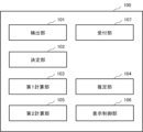
- FIG. 1 is a block diagram showing a configuration example of a degradation estimation system 100 according to the first embodiment.
- a deterioration estimation system 100 according to the first embodiment includes a detection unit 101 , a determination unit 102 , a first calculation unit 103 , an estimation unit 104 and a second calculation unit 105 .
- FIG. 1 shows a case where deterioration estimation system 100 further includes display control section 106 .
- the deterioration estimation system 100 does not have to include the display control unit 106 .
- the deterioration estimation system 100 is used for managing road surface deterioration using road surface images.
- Road surface deterioration includes, for example, cracks, potholes, rutting, and flatness anomalies. Cracks may be classified into different types, linear cracks and tortoiseshell cracks, depending on their shape.
- a straight crack is a single linear crack.
- a tortoiseshell crack is a tortoiseshell-shaped crack that occurs, for example, when vertical and horizontal straight cracks are connected. Cracks progress from linear cracks to tortoiseshell cracks and potholes.
- the degree of road surface deterioration is represented by the degree of deterioration.
- the value representing the degree of deterioration can be set to increase as road surface deterioration progresses.
- the degree of deterioration may be any index including degree of cracking, number of potholes, size of potholes, amount of rutting, or flatness.
- the degree of cracking is represented by the shape, length, width, area, number of cracks, or a combination thereof.
- Crack rate is an example of crack degree.
- the crack ratio is represented by, for example, 100 ⁇ (crack area/road section area). In this case, the value of the degree of deterioration ranges from 0% to 100%.
- the crack area is calculated by any method. The method for calculating the crack rate is not particularly limited, and known calculation methods other than those described above can be applied.
- the size of a pothole is represented by, for example, the area, width, length, or depth of the pothole, or a combination of these.
- the amount of rutting is the depth of the rut where the running track of the vehicle is lower than other road surfaces due to the load of the vehicle and the friction with the tires.
- the degree of deterioration may be determined based on a combination of a plurality of indicators representing the degree of road surface deterioration.
- the degree of deterioration may be a maintenance control index (MCI).
- MCI maintenance control index
- the value of MCI is the minimum result of calculating four defining equations using crack rate, rut depth, and flatness. MCI decreases as the road deteriorates.
- the road surface targeted by the deterioration estimation system 100 is not limited to general roads on which vehicles and people pass, but also includes vehicle test courses, airport runways and taxiways. That is, the deterioration estimation system 100 can widely target paved road surfaces.
- the detection unit 101 detects road surface deterioration from a road surface image obtained by photographing the road surface.
- the road surface image may include images other than the road surface, such as the sky, road signs, and buildings, as long as the road surface is photographed.
- the road surface image may be an image obtained by photographing only the road surface.
- Fig. 2 is a diagram showing an example of a road surface image of a road on which a car is running.
- the road surface image of FIG. 2 includes cracks as an example of road surface deterioration.
- the road surface image is captured by an in-vehicle camera such as a drive recorder.
- the type of camera is not limited to this, and various types of cameras may be used.
- the road surface image may be captured by a camera mounted on another mobile object such as a bicycle or drone, a camera carried by a person, or a fixed camera installed on the road.
- the road surface image may be taken by a person or automatically.
- FIG. 3 is a diagram showing an example of a device that is communicably connected to the deterioration estimation system 100 via a communication network 30 by wire or wirelessly.
- the display 20 is a display, tablet, or the like connected to a computer.
- An input device such as a mouse or keyboard may be connected to the display 20 .
- the display 20 may be configured as an input device.
- the display control unit 106 included in the deterioration estimation system 100 causes the display 20 to display various information. Information displayed by the display control unit 106 will be described later.
- a road surface image captured by a camera mounted on the vehicle 10 is transmitted to the deterioration estimation system 100.
- the transmitted road surface image may be stored in the database 40 .
- the detection unit 101 may acquire the road surface image from the database 40 .
- detection unit 101 may acquire a road surface image from the camera.
- the detection unit 101 may acquire the position information of the point where the road surface image was captured together with the road surface image.
- the location information includes, for example, latitude and longitude, GNSS (Global Navigation Satellite System), GPS (Global Positioning System) location information, or a location on a map.
- GNSS Global Navigation Satellite System
- GPS Global Positioning System
- the method of acquiring the position is not particularly limited.
- a device for receiving radio waves from GNSS satellites may be provided in a mobile object such as a camera or a car.
- the detection unit 101 compares the road surface image stored in the database in association with the position information and the newly captured road surface image, thereby obtaining the position information of the newly captured road surface image. may be obtained.
- the detection unit 101 may acquire the date and time when the road surface image was captured together with the road surface image.
- the detection unit 101 detects road surface deterioration using a known image recognition technique for the road surface image.
- the detection unit 101 may detect road surface deterioration using a machine-learned model.
- the detection unit 101 may determine whether the road surface is deteriorated for each pixel of the road surface image.
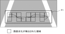
- FIG. 4 is a diagram showing an example of road surface deterioration detection results.
- the detection unit 101 may detect road surface deterioration included in the detection area F1 in the road surface image.
- the detection area F1 is an area to be detected for road surface deterioration.
- the area of the road surface in the road surface image is set as the detection area F1.
- the entire road surface image may be set as the detection area F1.
- Areas other than the road surface may be excluded from the detection area F1 for privacy protection.
- a nearby road surface may be set as the detection area F1, and the distant road surface may be excluded from the detection area F1.
- the range of these detection areas F1 is an example, and the range is set as appropriate.
- the position of the detection area F1 in the road surface image captured by the drive recorder fixed to the vehicle is fixed. Therefore, for example, a predetermined position on the road surface image is set as the detection area F1.
- the detection area F1 may be set by the user. Further, the detection unit 101 may recognize the road surface and set the recognized area of the road surface as the detection area F1.
- the detection unit 101 divides the road surface image into predetermined units. Then, the detection unit 101 may detect road surface deterioration for each divided unit. The detection unit 101 may divide the detection area in which the road surface deterioration is detected in the road surface image into predetermined units.
- the determination unit 102 determines the first area and the second area in the road surface image.
- the first area is an area where road surface deterioration can be detected from the road surface image.
- the second area is an area where it is difficult to detect road surface deterioration from the road surface image.
- the road surface image from which the first area and the second area are determined is also referred to as the first road surface image.
- the determining unit 102 may determine that there is no region corresponding to the second region in the first road surface image.
- the determining unit 102 may determine whether each divided unit is the first area or the second area.
- the determination unit 102 may determine the first region and the second region for each unit partitioned by the detection unit 101, for example. Alternatively, independently of the detection unit 101, the determination unit 102 may divide the road surface image into predetermined units regardless of whether the detection unit 101 divides the road surface image.
- the determination unit 102 may determine the first region and the second region in a unit different from the unit divided by the detection unit 101 .
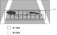
- FIG. 5 is a diagram showing an example of the determined first area and second area.
- the first area is indicated by a solid line frame
- the second area is indicated by a dotted line frame.
- the determination unit 102 determines, for example, the area where the road surface deterioration is detected by the detection unit 101 as the first area.
- the determining unit 102 may further determine, as the first area, an area determined by the detecting unit 101 to have no road surface deterioration. For example, an exposed road surface can be determined as the first area.
- the determining unit 102 may determine, as the second area, an area in which road surface deterioration is difficult to detect, among areas in which road surface deterioration has not been detected. Road surface deterioration may exist in areas where it is difficult to detect road surface deterioration.
- the determining unit 102 may determine the second area using a machine-learned model of an area where road surface deterioration is difficult to detect. It should be noted that the model for detecting road surface deterioration and the model for determining areas in which it is difficult to detect road surface deterioration may be the same. That is, the detection of road surface deterioration and the determination of the second area may be performed by the same process.
- the determination unit 102 may recognize the puddle by image recognition technology. Then, the determination unit 102 determines the region with the puddle as the second region.
- the second area is not limited to areas with puddles.
- the determining unit 102 may determine the second area to be an area in which other obstacles that shield the road surface are recognized.
- the second area may be an area covered with snow, an area covered with fallen leaves, an area hidden by other vehicles, and an area with litter.
- the determining unit 102 may determine, as the second area, an area with accumulated snow or fallen leaves in the same manner as the puddle.
- the second area is not limited to areas with shields. For example, even if there is no obstruction on the road surface, it may be difficult to detect deterioration of the road surface due to bad weather or sunset. In addition, road surfaces that are shaded by trees, buildings, and the like become dark, making it difficult to detect deterioration of the road surface. Therefore, the determining unit 102 may determine the shaded area as the second area. At this time, the road surface on which the light is shining and the obstruction does not fall may be determined as the first area.
- the determining unit 102 may set, as the second area, an area in which road surface deterioration is detected in a road surface image captured before the road surface image, among the areas in which road surface deterioration is not detected from the road surface image.
- the road surface image captured later is also referred to as the first road surface image
- the road surface image captured before the first road surface image is also referred to as the second road surface image.
- the second road surface image an image from which road deterioration can be easily detected may be selected.
- an image that does not include an area in which it is difficult to detect road surface deterioration may be selected as the second road surface image.
- an image taken on a sunny day may be selected as the second road surface image.
- the determining unit 102 refers to the database 40, for example. Then, the determination unit 102 acquires a second road surface image captured at the same point as the first road surface image. After that, the determining unit 102 compares the road surface deterioration detected from the first road surface image and the road surface deterioration detected from the second road surface image. The determining unit 102 determines, as a second area, an area in which road surface deterioration is detected in the second road surface image, among the areas in which road surface deterioration is not detected in the first road surface image.
- the second road surface image may be selected by the user.
- the determination unit 102 acquires a plurality of images from the database 40 in which road surface deterioration can be easily detected, and transfers the images to the display control unit 106 . Then, the display control unit 106 causes the user to display the plurality of acquired images.
- the determining unit 102 may acquire an image selected by the user from among the displayed images as the second road surface image.
- the determination unit 102 may determine the first area and the second area before the detection unit 101 detects road surface deterioration.
- the determination unit 102 uses a machine-learned model to determine a region in which road surface deterioration can be detected from the road surface image and a region in which road surface deterioration is difficult to detect from the road surface image. A region may be determined.
- the determination unit 102 compares the first road surface image and the second road surface image, and uses an existing image processing technique to determine an area with a degree of matching equal to or greater than a predetermined threshold as the first area. , a region having a degree of matching lower than the threshold may be determined as the second region. Then, the detection unit 101 detects road surface deterioration in the area determined as the first area.
- the first calculation unit 103 calculates the degree of deterioration of the first area based on the detection result from the first road surface image.
- the first calculation unit 103 calculates the degree of deterioration for each region partitioned by the detection unit 101, for example.
- the first calculation unit 103 calculates the crack rate for each partitioned region.
- the first calculation unit 103 may combine the degrees of deterioration for each area to calculate the degree of deterioration of the entire first area included in the first road surface image. As an example of merging deterioration degrees, the first calculation unit 103 may calculate an average deterioration degree of each region.
- the estimation unit 104 estimates the degree of deterioration of the second area based on the degree of deterioration in the past.
- the past deterioration degree is the degree of road surface deterioration detected from the second road surface image captured before the first road surface image.
- the second road surface image for example, the second road surface image used for determining the second area is used for estimating the degree of deterioration.
- the second road surface image used for estimating the degree of deterioration may be different from the image used for determining the second area.
- the estimation unit 104 estimates the degree of deterioration for each region partitioned by the detection unit 101 .
- the estimation unit 104 estimates the crack rate for each partitioned region.
- the estimation unit 104 may combine the degrees of deterioration for each area to estimate the degree of deterioration of the entire second area included in the first road surface image.
- the estimation unit 104 may calculate an average of the estimated deterioration degrees of each region.
- the estimation unit 104 may estimate the degree of deterioration acquired for the second road surface image as the degree of deterioration of the second region of the first road surface image. Alternatively, the estimation unit 104 may estimate the degree of deterioration of the second region by correcting the obtained degree of deterioration using a parameter. A case in which the estimation unit 104 corrects the degree of deterioration acquired with respect to the second road surface image will be described later.
- the estimation unit 104 acquires past deterioration degrees from a database.
- the database stores past deterioration degrees calculated for road surface deterioration detected from road surface images. Furthermore, in the database, the photographing location of the road surface image and the photographing date are stored in association with the degree of deterioration. Then, the estimation unit 104 acquires the past deterioration degree of the same point as the first road surface image from the database.
- the estimation unit 104 may refer to the deterioration level calculated from the latest second road surface image.
- the estimation unit 104 may obtain a second road surface image.
- the database stores past road surface images.
- the estimation unit 104 may calculate the degree of deterioration from the second road surface image.
- the process of calculating the degree of deterioration from the second road surface image by the estimating unit 104 can be reduced.
- the estimation unit 104 may identify a region in the second road surface image corresponding to the second region of the first road surface image. In this case, the estimation unit 104 acquires the degree of deterioration of the area identified from the second road surface image. However, the estimation unit 104 does not have to acquire the degree of deterioration of the area corresponding to the second area of the first road surface image. The estimation unit 104 may acquire the degree of deterioration calculated from the entire second road surface image or the entire detection area of the second road surface image.
- the estimation unit 104 may estimate the degree of deterioration obtained as described above for the second road surface image as the degree of deterioration of the second region of the first road surface image.
- each parameter affects how the road surface deterioration of the first road surface image progresses from the degree of deterioration at the time when the second road surface image was captured.
- the estimating unit 104 estimates the degree of deterioration of the second region, for example, by adding the degree of deterioration acquired for the second road surface image and a value obtained by weighting an arbitrary parameter.
- the estimating unit 104 may estimate the degree of deterioration of the second region by adding a plurality of values obtained by weighting the respective parameters to the degree of deterioration obtained for the second road surface image.
- the weights assigned to the parameters represent the degree of influence each parameter has on the progression of road surface deterioration.
- the degree of deterioration detected from the first road surface image is used, and for the second region, a value obtained by correcting the degree of deterioration detected from the second road surface image with a parameter is used.
- the degree of deterioration of the road surface is estimated in
- the type of parameter is not particularly limited.
- the parameter may be at least one of precipitation, presence or absence of puddles, flatness, and traffic volume.
- the degree of deterioration of the second area is represented by the following formula.
- Degree of deterioration of second area degree of deterioration detected from second road surface image+(precipitation amount ⁇ W1+puddle ⁇ W2+flatness ⁇ W3+period ⁇ W4+ . . . )
- precipitation, puddles, flatness, and duration each represent parameters.
- W1, W2, W3, and W4 represent the weight of each parameter.
- the estimation unit 104 may automatically acquire parameter values. A case where the estimating unit 104 acquires parameters input by the user will be described later in a second embodiment. Each parameter will be described below.
- the estimation unit 104 may estimate the degree of deterioration of the second region based on the total amount of rainfall from the time when the second road surface image was captured to the time when the first road surface image was captured. It is predicted that road surface deterioration progresses as the total amount of rainfall increases. Therefore, the estimation unit 104 adds a larger value to the degree of deterioration acquired for the second road surface image as the total amount of rainfall increases.
- the estimation unit 104 refers to a database that stores precipitation.
- the database can store actually observed precipitation data and the like.
- the amount of precipitation to be stored may not be the amount of precipitation actually observed, but may be the average amount of precipitation for each predetermined period of a normal year.
- the estimation unit 104 for example, refers to monthly average precipitation.
- the estimating unit 104 acquires the total amount of rainfall from the time when the second road surface image was captured to the time when the first road surface image was captured.
- the amount of precipitation that is obtained does not have to be an accurate amount of precipitation.
- the estimating unit 104 may acquire the total amount of rainfall between the times when the two road surface images were captured, but the acquired amount of rainfall is not limited to this.
- the estimating unit 104 may acquire the total amount of precipitation including the amount of precipitation for several hours before and after the time of photographing the road surface image, or for several days before and after the time of photographing the road surface image.
- the estimation unit 104 may estimate the degree of deterioration of the second area based on whether or not a puddle is captured in the first road surface image, as an example of the parameter.
- the parameter may be set to '1' when there is a puddle, and set to '0' when there is no puddle.
- This parameter may be applied to the second area included in the road surface image in which the puddle is captured, regardless of whether or not there is a puddle in each second area.
- a road surface with puddles may have poor drainage, and it is predicted that road surface deterioration will progress easily. Therefore, if there is a puddle on the road surface, the estimating unit 104 adds a predetermined value to the degree of deterioration acquired for the second road surface image for estimating the degree of deterioration of the second area.
- the estimation unit 104 may estimate the degree of deterioration of the second area based on whether there is a puddle in the second area, as an example of the parameter. For example, a parameter "1" is set for a second region with puddles, and a parameter "0" is set for a second region without puddles. A road surface with puddles may be more depressed than other road surfaces. Therefore, it is predicted that a flatness anomaly, which is an example of road surface deterioration, exists. In addition, it is predicted that the water accumulated on the dented road surface will accelerate the deterioration of the road surface. If there is a puddle in the second area, the estimating unit 104 adds a predetermined value to the degree of deterioration acquired for the second road surface image.
- the estimation unit 104 may estimate the degree of deterioration of the second area based on the flatness of the road surface at the time when the first road surface image was captured, as an example of parameters.
- Flatness can sometimes be measured even if it is difficult to detect road surface deterioration from a road surface image.
- flatness can be measured by methods other than image recognition, even on rainy days and even when there are puddles on the road surface.
- the IRI is an index that associates the road surface with the ride comfort of the driver, and expresses the degree of unevenness as a numerical value.
- the IRI may be calculated based on measurement data obtained by measuring the road surface with sensors.
- the IRI may be calculated based on the value of an acceleration sensor attached to the vehicle while the vehicle is running.
- the IRI is calculated based on the vertical acceleration value included in the acceleration acquired at the detection position. Note that the calculation method of the IRI is not limited to the above, and a known calculation method can be adopted.
- the estimation unit 104 acquires a value representing flatness from a vehicle that measures flatness while capturing the first road surface image.
- a road surface with low flatness and unevenness is predicted to have a high degree of deterioration of the road surface detected from the road surface image. Therefore, the estimation unit 104 adds a larger value to the degree of deterioration acquired for the second road surface image as the flatness is lower.
- the estimation unit 104 may estimate the degree of deterioration of the second region based on the length of the period from when the second road surface image was captured to when the first road surface image was captured, as an example of a parameter. good. It is predicted that the longer the period, the more the road surface deterioration progresses.
- a period of time may be represented, for example, by any number of years, months, days, or hours.
- the estimating unit 104 acquires, for example, the date and time when the first road surface image and the second road surface image were captured, and calculates the length of the period. However, the length of the period used for estimation does not have to be an exact value.
- the estimation unit 104 may estimate the degree of deterioration of the second area based on the traffic volume as an example of the parameter. For example, the estimation unit 104 may estimate the degree of deterioration of the second area based on the total traffic volume from the time when the second road surface image was captured to the time when the first road surface image was captured. It is predicted that road surface deterioration progresses as the total traffic volume increases. Traffic volume represents, for example, the number of vehicles passing on the road surface.
- the estimation unit 104 refers to a database that stores traffic volume.
- the database may store annual traffic volume data, weekly traffic volume data, or the like.
- the traffic volume that is stored may be the average traffic volume for the point or region where the road surface image was taken, rather than the actual counted traffic volume.
- the estimation unit 104 acquires the total traffic volume from the time when the second road surface image was captured to the time when the first road surface image was captured.
- the traffic volume obtained does not have to be an accurate traffic volume.
- the estimating unit 104 may acquire the total traffic volume between the times when the two road surface images were captured, but the acquired traffic volume is not limited to this.
- the estimating unit 104 may acquire the total traffic volume including the traffic volume for several hours before and after the time of photographing the road surface image, or for several days before and after the time of photographing the road surface image.
- the estimation unit 104 adds a larger value to the degree of deterioration acquired for the second road surface image as the total traffic volume acquired increases.
- the values obtained for the above various parameters may be displayed by the display control unit 106. By displaying the values, the user can understand on what parameters the degree of deterioration of the second area is estimated.
- the estimation unit 104 may use any method to set the weight assigned to each parameter. For example, weights may be set by a machine-learned model. Also, whether or not to use each parameter may be set by the model.
- the weight of parameters related to traffic may be set higher than other parameters.
- the weight may be set so that the degree of influence of traffic on road surface deterioration increases in areas with heavy traffic.
- the estimating unit 104 acquires, for example, the traffic volume for a predetermined period at the point where the road surface image was captured. Then, the estimating unit 104 changes the weight of the parameter, which is the total traffic volume from the time when the second road surface image was captured to the time when the first road surface image was captured, according to the acquired traffic volume.
- the estimation unit 104 changing the weight of the parameter according to the traffic volume is an example of estimating the degree of deterioration of the second region based on the traffic volume.
- the estimation unit 104 may estimate the degree of deterioration of the second area based on the amount of precipitation at the time when the first road surface image was captured. For example, the estimating unit 104 may set the weight of the parameter relating to the amount of precipitation to be greater than that of the other parameters during the rainy season or the snowy season. That is, the weight may be set so that the degree of influence of the amount of rain on the road surface deterioration is greater in the period of heavy rainfall.
- the estimating unit 104 may acquire the amount of rainfall on the day the first road surface image was captured, or the amount of rainfall including the days before and after the day when the first road surface image was captured. Alternatively, the estimating unit 104 may acquire the amount of rainfall during the same period of a normal year on the date when the first road surface image was captured. The estimating unit 104 weights, for example, a parameter that is the total amount of rainfall from the time when the second road surface image was captured to the time when the first road surface image was captured, based on the acquired rainfall amount.
- the degree of deterioration of the road surface can be estimated more accurately.
- the second calculation unit 105 calculates the degree of deterioration of the photographed road surface based on the calculated degree of deterioration of the first area and the estimated degree of deterioration of the second area.
- the degree of deterioration calculated by the second calculation unit 105 is estimated as the degree of deterioration of the road surface at the time of capturing the first road surface image.
- the second calculation unit 105 weights the deterioration degrees of the first region and the second region by the areas of the first region and the second region, respectively, and sums them up, thereby calculating the deterioration degree of the photographed road surface. calculate.
- the degree of deterioration estimated by the second calculation unit 105 may be stored in the database as road surface data at the time when the first road surface image was captured. By storing the estimated degree of deterioration in the database, it becomes possible to refer to it together with data of other degrees of deterioration at the same point at a later date.
- the database may also store the detection result by the detection unit 101, the calculation result by the first calculation unit 103, and the estimation result by the estimation unit 104 in association with the degree of deterioration.
- the display control unit 106 displays the road surface deterioration degree calculated by the second calculation unit 105 .
- the degree of deterioration may be displayed in different colors depending on the range of heights of the degree of deterioration. For example, a high degree of deterioration may be displayed in red, a low degree of deterioration in green, and an intermediate degree of deterioration in yellow.
- the display control unit 106 may further display the first road surface image.
- the display control unit 106 may display the first area and the second area on the road surface image in different modes.
- the first area and the second area may be indicated by different colored frames.
- the first area may be indicated by a solid line frame and the second area may be indicated by a dotted line frame.
- the display control unit 106 may indicate the detection area on the road surface image. For example, on the display, a frame indicating the detection region is displayed with a frame of a different color or a different thickness from the first region and the second region. For privacy protection, the display control unit 106 may display the road surface image by lowering the resolution of the area other than the detection area.
- the display control unit 106 may reflect the calculated degree of deterioration on the map representing the degree of deterioration of the road surface.
- the road surface on the map is divided into predetermined ranges.
- Each partitioned area may be given a color according to the range of the degree of deterioration.
- the arrow may be displayed in a color corresponding to the range of the degree of deterioration.
- FIG. 6 is a flowchart showing an operation example of the deterioration estimation system 100 according to the first embodiment.
- the detection unit 101 detects road surface deterioration from the first road surface image (step S1).
- the detection unit 101 transfers the detected road surface deterioration to the first calculation unit 103 .
- the determination unit 102 determines a first area where road surface deterioration can be detected and a second area where road surface deterioration is difficult to detect in the first road surface image (step S2).
- Step S2 may be performed before step S1.
- the first calculation unit 103 calculates the degree of deterioration of the first area based on the detection result from the first road surface image (step S3).
- the first calculator 103 transfers the calculated degree of deterioration to the second calculator 105 .
- the estimating unit 104 estimates the degree of deterioration of the second area based on the degree of deterioration of the road surface detected from the second road surface image captured before the first road surface image (step S4).
- the estimation unit 104 transfers the estimated degree of deterioration to the second calculation unit 105 .
- the second calculation unit 105 calculates the degree of deterioration of the photographed road surface based on the calculated degree of deterioration of the first area and the estimated degree of deterioration of the second area (step S5). After step S5, the display control unit 106 may display the calculated degree of deterioration on the display.
- the deterioration estimation system 100 detects the road surface deterioration degree from the road surface image. Then, the deterioration estimation system 100 calculates the degree of deterioration of the road surface based on the degree of deterioration calculated for the area where road surface deterioration is detectable and the degree of deterioration estimated for the area where road surface deterioration is difficult to detect. Therefore, the user can estimate the degree of deterioration of the road surface even if there is an area in which it is difficult to detect the deterioration of the road surface in the image of the road surface.
- FIG. 7 is a diagram showing a configuration example of a degradation estimation system 100 according to the second embodiment.
- a degradation estimation system 100 according to the second embodiment differs from the degradation estimation system 100 according to the first embodiment in that a reception unit 107 is provided.
- a reception unit 107 is provided.
- description is partially abbreviate
- the display control unit 106 displays the first road surface image.
- the first road surface image is an image for which detection of road surface deterioration and estimation of the degree of deterioration are performed, as in the first embodiment.
- the reception unit 107 receives that the first road surface image includes an area where it is difficult to detect road surface deterioration. For example, the receiving unit 107 receives from the user that an area in which it is difficult to detect road surface deterioration is included.
- the accepting unit 107 accepts button presses by the user. The button is displayed on the display by the display control unit 106, for example.
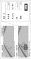
- FIG. 8 is an image showing an example of the first screen that the display control unit 106 displays on the display.
- the first screen includes a button for accepting that an area where it is difficult to detect road surface deterioration is included.
- the first screen includes the first road surface image and the road surface deterioration detection result by the detection unit 101 .
- the display control unit 106 may display the road surface deterioration detected from the first road surface image. For example, as shown in FIG. 8, the display control unit 106 superimposes a frame surrounding an area where road surface deterioration is detected on the road surface image and displays the road surface image. Alternatively, the display control unit 106 may display a road surface image in which the detected road surface deterioration is colored.
- the display control unit 106 may display the degree of deterioration calculated for the road surface deterioration detected from the first road surface image. This degree of deterioration can be calculated by the first calculator 103 . In FIG. 8, the crack rate is displayed as an example of the degree of deterioration. Furthermore, the display control unit 106 may display the degree of deterioration measured in the past at the same point. In FIG. 8, the past deterioration degree and the deterioration degree measured from the first road surface image are plotted on a graph.
- an "estimate when it rains" button is displayed as an example of a button that accepts that an area where it is difficult to detect road surface deterioration is included.
- the form of this embodiment is not limited to use in rainy weather.
- the button display mode can be changed in various ways.
- the user confirms, for example, that the displayed road surface image includes puddles, or that the road surface image was taken in rainy weather. Alternatively, the user may confirm that the area where road surface deterioration is not detected includes an area where road surface deterioration may exist. In response to the confirmation, the user presses a button such as an "estimation in rainy weather" button.
- the determination unit 102 determines the second area in response to the reception by the reception unit 107, for example, similarly to the first embodiment.
- the determining unit 102 may determine the area specified by the user as the second area.
- the receiving unit 107 may receive the designation of the area from the user and receive the input to set the designated area as the second area.
- the estimation unit 104 estimates the degree of deterioration of the second region, similar to the processing in the first embodiment. Further, the second calculation unit 105 calculates the deterioration of the road surface photographed in the first road surface image based on the degree of deterioration of the first area and the degree of deterioration of the second area, similarly to the processing in the first embodiment. Calculate degrees.
- the accepting unit 107 may further accept input of the parameter by the user. .
- the display control unit 106 displays the second screen for receiving input of parameters.
- FIG. 9 is an image showing an example of the second screen that the display control unit 106 causes the display to display.
- the display control unit 106 may switch the first screen to the second screen in response to pressing of the "rainy weather estimation" button on the first screen.
- the second screen in FIG. 9 includes fields for accepting input of parameters including precipitation, presence or absence of puddles, flatness, and length of period.
- parameters to be input are not limited to these.
- the amount of precipitation may be, for example, the total amount of precipitation from the time when the second road surface image was captured to the time when the first road surface image was captured.
- the presence or absence of a puddle may be whether or not a puddle is captured in the first road surface image.
- Flatness may be an IRI calculated based on the values of a running acceleration sensor attached to the vehicle.
- the length of the period is, for example, the length of the period from when the second road surface image is captured to when the first road surface image is captured.
- the second screen may include, for example, a radio button that is pressed when the image is taken in rainy weather. Depending on the input of the radio button, it may be possible to input to the fields below the button.
- the display control unit 106 causes the parameters acquired by the estimation unit 104 to be displayed.
- the automatically input parameters may be modified by the user via the reception unit 107 .
- the first road surface image may be displayed on the second screen as the "currently captured image”.
- the first area and the second area determined by the determining unit 102 may be shown on the first road surface image.
- the “previous road surface image” may be displayed on the second screen.
- the display of the second screen may be omitted. For example, if the estimation of the degree of deterioration does not involve addition of weighted values of various parameters, the display of the second screen may be omitted.
- the display control unit 106 displays the third screen.
- the third screen displays the calculation result of the degree of deterioration at the time when the first road surface image is captured by the second calculation unit 105 .
- FIG. 10 is an image showing an example of the third screen that the display control unit 106 causes the display to display.
- the display control unit 106 may switch the second screen to the third screen and display it in response to pressing of the "estimate" button on the second screen.
- the display control unit 106 changes the first screen to the third screen in response to pressing of a button such as the "rainy weather estimation” button on the first screen. screen may be displayed.
- the third screen displays the degree of deterioration calculated by the second calculation unit 105.
- the degree of deterioration calculated by the second calculator 105 "estimated crack rate" is displayed in FIG.
- the degree of deterioration calculated by the second calculator is plotted on a graph.
- the degree of deterioration measured from the first road surface image and the degree of deterioration estimated may be displayed in different manners.
- FIG. 11 is a flowchart showing an operation example of the deterioration estimation system 100 according to the second embodiment.
- the detection unit 101 detects road surface deterioration from the first road surface image of the road surface (step S21).
- the detection unit 101 transfers the detected road surface deterioration to the first calculation unit 103 and the display control unit 106 .
- the display control unit 106 may display the detected road surface deterioration. For example, the display control unit 106 causes the first screen in FIG. 8 to be displayed.
- the receiving unit 107 receives that the first road surface image includes an area where it is difficult to detect road surface deterioration (step S22). For example, the reception unit 107 receives from the user the pressing of the “rainy weather estimation” button in FIG. 8 .
- the determination unit 102 determines the second area in the first road surface image in which it is difficult to detect road surface deterioration in response to the reception by the reception unit 107 (step S23).
- the determining unit 102 passes the determined second region to the estimating unit 104 .
- the determination unit 102 determines the first area in which road surface deterioration can be detected (step S24).
- the determination unit 102 transfers the determined first area to the first calculation unit 103 .
- the determination of the first area may be performed by the same processing as the determination of the second area in step S23.
- the determination of the first region may be performed at any timing between before step S21 and before step S25.
- the first calculation unit 103 calculates the degree of deterioration of the first area based on the detection result from the first road surface image (step S25).
- the first calculator 103 transfers the calculated degree of deterioration to the second calculator 105 .
- Step S25 may be executed at any timing after road surface deterioration is detected and the first area is determined.
- the estimation unit 104 estimates the degree of deterioration of the second area based on the degree of deterioration in the past (step S26).
- the past deterioration degree is the degree of road surface deterioration detected from the second road surface image captured before the first road surface image.
- the estimation unit 104 acquires the degree of deterioration of the second road surface image from the database.
- the estimation unit 104 transfers the estimated degree of deterioration to the second calculation unit 105 .
- the second calculation unit 105 calculates the degree of deterioration of the photographed road surface based on the calculated degree of deterioration of the first area and the estimated degree of deterioration of the second area (step S27). After step S27, the display control unit 106 may display the calculated degree of deterioration on the display.
- the deterioration estimation system 100 determines the second area in response to the fact that the first road surface image includes an area in which road surface deterioration is difficult to detect, and determines the second area. Estimate the degree of deterioration. Therefore, determination of the second region can be performed only when necessary. In addition, even if a road surface image obtained by photographing the road surface includes an area where it is difficult to detect road surface deterioration, the degree of deterioration of the road surface can be estimated.
- the degradation estimation system 100 according to the second embodiment may further include a determination section.
- the determination unit determines whether or not there is a possibility that an area in which it is difficult to detect road surface deterioration is included based on the weather information at the time when the first road surface image was captured.
- the determination unit acquires the weather information of the location where the road surface image was captured or of the area.
- Weather information is, for example, information about weather, amount of precipitation, or amount of snow.
- Weather information indicates any of a variety of weather conditions, such as sunny, cloudy, rainy, snowy, and foggy.
- Weather information may include wind speed, sunrise time, sunset time, and the like.
- the determination unit acquires the date when the road surface image was taken or the weather information at the time of shooting.
- the determination unit may acquire weather information within a predetermined range before and after the day when the road surface image was captured. If the weather information indicates rain, puddles may form on the road surface. Therefore, the determination unit determines that there is a possibility that an area in which it is difficult to detect road surface deterioration is included.
- the determination unit may determine that there is a possibility that a road surface image captured on a day with high wind speed or the day after a day with high wind speed includes an area where it is difficult to detect road surface deterioration. Further, the determination unit may determine that road surface images captured within a predetermined range before and after sunset may include an area in which it is difficult to detect deterioration of the road surface due to shadows.
- the reception unit 107 receives from the determination unit that an area where it is difficult to detect road surface deterioration is included.
- the determination unit 102 determines the second area in response to the reception by the reception unit 107. That is, the determining unit 102 determines the second area based on the weather information at the time when the first road surface image was captured, and determines that the road surface deterioration may be difficult to detect. You may
- each component of the degradation estimation system 100 represents a functional unit block. A part or all of each component of degradation estimation system 100 may be realized by any combination of computer 500 and a program.
- FIG. 12 is a block diagram showing an example of the hardware configuration of computer 500.
- computer 500 includes, for example, CPU (Central Processing Unit) 501, ROM (Read Only Memory) 502, RAM (Random Access Memory) 503, program 504, storage device 505, drive device 507, communication interface 508 , an input device 509 , an input/output interface 511 and a bus 512 .
- CPU Central Processing Unit
- ROM Read Only Memory
- RAM Random Access Memory
- the program 504 includes instructions for realizing each function of the deterioration estimation system 100.
- the program 504 is stored in advance in the ROM 502 , RAM 503 and storage device 505 .
- CPU 501 realizes each function of deterioration estimation system 100 by executing instructions included in program 504 .
- the CPU 501 of the deterioration estimation system 100 executes instructions included in the program 504 to implement the functions of the deterioration estimation system 100 .
- the RAM 503 may store data processed in each function of the deterioration estimation system 100 .
- the road surface image may be stored in the RAM 503 of the computer 500 .
- the drive device 507 reads from and writes to the recording medium 506 .
- Communication interface 508 provides an interface with a communication network.
- the input device 509 is, for example, a mouse or a keyboard, and receives information input from the user.
- the output device 510 is, for example, a display, and outputs (displays) information to the user.
- the input/output interface 511 provides an interface with peripheral devices.
- a bus 512 connects each of these hardware components.
- the program 504 may be supplied to the CPU 501 via a communication network, or may be stored in the recording medium 506 in advance, read by the drive device 507 and supplied to the CPU 501 .
- FIG. 12 Note that the hardware configuration shown in FIG. 12 is an example, and components other than these may be added, and some components may not be included.
- the deterioration estimation system 100 may be implemented by any combination of computers and programs that differ for each component.
- a plurality of components included in degradation estimation system 100 may be realized by any combination of a single computer and a program.
- each component of the degradation estimation system 100 may be realized by one or more processors.
- the processor may be composed of a single chip, or may be composed of multiple chips connected via a bus.
- a part or all of each component of the deterioration estimation system 100 may be realized by a combination of the processor and the program described above.
- the plurality of computers, circuits, etc. may be centrally arranged or distributed. .
- At least part of the degradation estimation system 100 may be provided in SaaS (Software as a Service) format. That is, at least part of the functions for realizing deterioration estimation system 100 may be executed by software executed via a network.
- SaaS Software as a Service
- [Appendix 1] a detection means for detecting road surface deterioration from a first road surface image obtained by photographing the road surface; Determination means for determining a first area in which road surface deterioration can be detected and a second area in which road surface deterioration is difficult to detect in the first road surface image; a first calculation means for calculating the degree of deterioration of the first area based on the detection result from the first road surface image; estimation means for estimating the degree of deterioration of the second area based on the degree of deterioration of road surface deterioration detected from a second road surface image obtained by photographing the road surface before the first road surface image; A deterioration estimation system comprising: second calculation means for calculating the degree of deterioration of the road surface based on the calculated degree of deterioration of the first area and the estimated degree of deterioration of the second area.
- Appendix 3 3. The deterioration estimation system according to appendix 1 or 2, wherein the estimating means estimates the degree of deterioration of the second area by correcting the degree of deterioration detected from the second road surface image with a parameter.
- the estimating means estimates the degree of deterioration of the second region using, as the parameter, the total amount of rainfall from the time when the second road surface image was captured to the time when the first road surface image was captured.
- Appendix 5 The deterioration estimation system according to appendix 4, wherein the estimation means further estimates the degree of deterioration of the second area using, as the parameter, whether or not a puddle is captured in the first road surface image.
- Appendix 6 The deterioration estimation system according to appendix 4 or 5, wherein the estimating means further estimates the degree of deterioration of the second area using whether or not there is a puddle in the second area as the parameter.
- the estimating means further uses, as the parameter, the flatness of the road surface at the time when the first road surface image was captured, to estimate the degree of deterioration of the second area.
- the estimating means further estimates the degree of deterioration of the second area by using, as the parameter, the length of the period from when the second road surface image was captured to when the first road surface image was captured.
- the deterioration estimation system according to any one of Appendices 4 to 7.
- the estimating means further estimates the degree of deterioration of the second area by using, as the parameter, the total traffic volume from the time when the second road surface image was captured to the time when the first road surface image was captured.
- the deterioration estimation system according to any one of appendices 4 to 8.
- the estimation means estimates the degree of deterioration of the second region by changing, among the plurality of parameters, the weight of the sum of the traffic volumes according to the traffic volume of the area including the road surface. degradation estimation system.
- the estimating means estimates the degree of deterioration of the second region by changing a weight of the sum of the rainfall amounts among the plurality of parameters according to the rainfall amount at the time when the first road surface image is captured.
- the deterioration estimation system according to any one of Appendices 4 to 10.
- Appendix 12 11. The deterioration estimation system according to any one of appendices 3 to 10, wherein the estimating means estimates the degree of deterioration of the second area based on the parameter input by the user.
- Appendix 13 3. The deterioration estimation system according to appendix 1 or 2, wherein the estimation means estimates the degree of road surface deterioration detected from the second road surface image as the degree of deterioration of the second area.
- the determining means determines the second area in response to the acceptance.
- the deterioration estimation system according to any one of appendices 1 to 13.
- the determining means determines the second area in accordance with a determination that there is a possibility that an area in which deterioration of the road surface is difficult to detect is included, based on weather information at a time when the first road surface image was captured.
- the deterioration estimation system according to any one of appendices 1 to 14.
- [Appendix 16] Detecting road surface deterioration from the first road surface image of the road surface, Determining a first area where road surface deterioration can be detected and a second area where road surface deterioration is difficult to detect in the first road surface image, calculating the degree of deterioration of the first area based on the detection result from the first road surface image; estimating the degree of deterioration of the second region based on the degree of deterioration of road surface deterioration detected from a second road surface image obtained by photographing the road surface before the first road surface image; A deterioration estimation method, wherein the degree of deterioration of the road surface is calculated based on the calculated degree of deterioration of the first area and the estimated degree of deterioration of the second area.
- REFERENCE SIGNS LIST 100 deterioration estimation system 101 detection unit 102 determination unit 103 first calculation unit 104 estimation unit 105 second calculation unit 106 display control unit 107 reception unit 10 vehicle 20 display 30 communication network 40 database
Landscapes
- Physics & Mathematics (AREA)
- General Physics & Mathematics (AREA)
- Traffic Control Systems (AREA)
Abstract
La présente divulgation concerne un système d'estimation de détérioration qui comprend : un moyen de détection qui détecte une détérioration de surface de route à partir d'une première image de surface de route obtenue par photographie d'une surface de route ; un moyen de détermination qui détermine, dans la première image de surface de route, une première région pour laquelle une détection de la détérioration de surface de route est possible, et une seconde région pour laquelle une détection de la détérioration de surface de route est difficile ; un premier moyen de calcul qui calcule le degré de détérioration dans la première région sur la base des résultats de détection provenant de la première image de surface de route ; un moyen d'estimation qui estime le degré de détérioration dans la seconde région sur la base du degré de détérioration de surface de route détecté à partir d'une seconde image de surface de route obtenue par photographie de la surface de route à l'avant de la première image de surface de route ; et un second moyen de calcul qui calcule le degré de détérioration de la surface de route sur la base du degré de détérioration calculé dans la première région et du degré de détérioration estimé dans la seconde région.
Priority Applications (1)
| Application Number | Priority Date | Filing Date | Title |
|---|---|---|---|
| PCT/JP2022/001143 WO2023135749A1 (fr) | 2022-01-14 | 2022-01-14 | Système d'estimation de détérioration, procédé d'estimation de détérioration et support d'enregistrement |
Applications Claiming Priority (1)
| Application Number | Priority Date | Filing Date | Title |
|---|---|---|---|
| PCT/JP2022/001143 WO2023135749A1 (fr) | 2022-01-14 | 2022-01-14 | Système d'estimation de détérioration, procédé d'estimation de détérioration et support d'enregistrement |
Publications (1)
| Publication Number | Publication Date |
|---|---|
| WO2023135749A1 true WO2023135749A1 (fr) | 2023-07-20 |
Family
ID=87278604
Family Applications (1)
| Application Number | Title | Priority Date | Filing Date |
|---|---|---|---|
| PCT/JP2022/001143 WO2023135749A1 (fr) | 2022-01-14 | 2022-01-14 | Système d'estimation de détérioration, procédé d'estimation de détérioration et support d'enregistrement |
Country Status (1)
| Country | Link |
|---|---|
| WO (1) | WO2023135749A1 (fr) |
Citations (6)
| Publication number | Priority date | Publication date | Assignee | Title |
|---|---|---|---|---|
| JP2013140448A (ja) * | 2011-12-28 | 2013-07-18 | Fujitsu Ltd | 路面調査プログラム及び路面調査装置 |
| JP2019114495A (ja) * | 2017-12-26 | 2019-07-11 | 岩崎電気株式会社 | 道路灯照明器具 |
| JP2019185443A (ja) * | 2018-04-11 | 2019-10-24 | 株式会社村田製作所 | 道路管理システム、道路管理方法、及び道路管理プログラム |
| JP2021060656A (ja) * | 2019-10-03 | 2021-04-15 | エヌ・ティ・ティ・コムウェア株式会社 | 道路損傷判定装置、道路損傷判定方法及び道路損傷判定プログラム |
| WO2021193148A1 (fr) * | 2020-03-27 | 2021-09-30 | 日本電気株式会社 | Dispositif de diagnostic de détérioration de route, système de diagnostic de détérioration de route, procédé de diagnostic de détérioration de route et support d'enregistrement |
| JP2021162868A (ja) * | 2020-03-31 | 2021-10-11 | 日本電気株式会社 | 劣化表示システム、劣化表示方法、及び、プログラム |
-
2022
- 2022-01-14 WO PCT/JP2022/001143 patent/WO2023135749A1/fr unknown
Patent Citations (6)
| Publication number | Priority date | Publication date | Assignee | Title |
|---|---|---|---|---|
| JP2013140448A (ja) * | 2011-12-28 | 2013-07-18 | Fujitsu Ltd | 路面調査プログラム及び路面調査装置 |
| JP2019114495A (ja) * | 2017-12-26 | 2019-07-11 | 岩崎電気株式会社 | 道路灯照明器具 |
| JP2019185443A (ja) * | 2018-04-11 | 2019-10-24 | 株式会社村田製作所 | 道路管理システム、道路管理方法、及び道路管理プログラム |
| JP2021060656A (ja) * | 2019-10-03 | 2021-04-15 | エヌ・ティ・ティ・コムウェア株式会社 | 道路損傷判定装置、道路損傷判定方法及び道路損傷判定プログラム |
| WO2021193148A1 (fr) * | 2020-03-27 | 2021-09-30 | 日本電気株式会社 | Dispositif de diagnostic de détérioration de route, système de diagnostic de détérioration de route, procédé de diagnostic de détérioration de route et support d'enregistrement |
| JP2021162868A (ja) * | 2020-03-31 | 2021-10-11 | 日本電気株式会社 | 劣化表示システム、劣化表示方法、及び、プログラム |
Similar Documents
| Publication | Publication Date | Title |
|---|---|---|
| CN109476310B (zh) | 一种基于舒适度的自动驾驶车速控制方法 | |
| JP7195021B2 (ja) | データ収集装置、道路状態評価支援装置、及びプログラム | |
| US10967869B2 (en) | Road surface condition estimation apparatus and road surface condition estimation method | |
| JP6713505B2 (ja) | 舗装情報収集点検システム、舗装情報収集点検方法、及びプログラム | |
| JP6454109B2 (ja) | 路面状態管理装置及び路面状態管理プログラム | |
| CN103985250B (zh) | 轻量级的全息道路交通状态视觉检测装置 | |
| CN107085944B (zh) | 一种交通数据处理系统及方法 | |
| WO2021199915A1 (fr) | Système d'affichage de dégradation, procédé d'affichage de dégradation et support de stockage | |
| JP6490003B2 (ja) | 道路管理システム及び方法、道路情報収集装置及びプログラム、並びに、道路情報管理装置及びプログラム | |
| JP7314693B2 (ja) | 路面性状調査システム、路面性状調査方法、及び路面性状調査プログラム | |
| CN103938531B (zh) | 激光道路错台检测系统和方法 | |
| JP6678267B1 (ja) | 道路不具合検出装置、道路不具合検出方法及び道路不具合検出プログラム | |
| US20240167962A1 (en) | System and method for automatic monitoring of pavement condition | |
| JP6647171B2 (ja) | 情報処理装置、情報処理方法、及びプログラム | |
| CN110851948A (zh) | 非结构化道路条件下的行车环境态势评估方法及评估装置 | |
| Luo et al. | Estimation of water film depth for rutting pavement using IMU and 3D laser imaging data | |
| WO2022190204A1 (fr) | Dispositif et procédé de calcul de risque d'occurrence, système d'affichage de risque d'occurrence et support non transitoire lisible par ordinateur dans lequel est stocké un programme de calcul de risque d'occurrence | |
| WO2023135749A1 (fr) | Système d'estimation de détérioration, procédé d'estimation de détérioration et support d'enregistrement | |
| JP6965536B2 (ja) | 情報処理システム、評価システム、情報処理方法およびプログラム | |
| CN109344903A (zh) | 基于车载感知数据的城市道路路面故障实时检测方法 | |
| US20230135343A1 (en) | Degradation display system, degradation display method, and recording medium | |
| US20230081098A1 (en) | Deterioration diagnosis device, deterioration diagnosis method, and recording medium | |
| JP2012203722A (ja) | 地物選定システム、地物選定プログラム及び地物選定方法 | |
| KR20220055309A (ko) | 강우정보에 따른 도로 위험도 예측 시스템 | |
| WO2023100309A1 (fr) | Dispositif de détermination d'état, procédé de détermination de condition et support d'enregistrement |
Legal Events
| Date | Code | Title | Description |
|---|---|---|---|
| 121 | Ep: the epo has been informed by wipo that ep was designated in this application |
Ref document number: 22920274 Country of ref document: EP Kind code of ref document: A1 |