WO2023132064A1 - 量子演算装置及び量子演算装置の製造方法 - Google Patents
量子演算装置及び量子演算装置の製造方法 Download PDFInfo
- Publication number
- WO2023132064A1 WO2023132064A1 PCT/JP2022/000385 JP2022000385W WO2023132064A1 WO 2023132064 A1 WO2023132064 A1 WO 2023132064A1 JP 2022000385 W JP2022000385 W JP 2022000385W WO 2023132064 A1 WO2023132064 A1 WO 2023132064A1
- Authority
- WO
- WIPO (PCT)
- Prior art keywords
- substrate
- quantum
- substrates
- arithmetic device
- manufacturing
- Prior art date
- Legal status (The legal status is an assumption and is not a legal conclusion. Google has not performed a legal analysis and makes no representation as to the accuracy of the status listed.)
- Ceased
Links
Images














Classifications
-
- G—PHYSICS
- G06—COMPUTING OR CALCULATING; COUNTING
- G06N—COMPUTING ARRANGEMENTS BASED ON SPECIFIC COMPUTATIONAL MODELS
- G06N10/00—Quantum computing, i.e. information processing based on quantum-mechanical phenomena
- G06N10/40—Physical realisations or architectures of quantum processors or components for manipulating qubits, e.g. qubit coupling or qubit control
-
- H—ELECTRICITY
- H10—SEMICONDUCTOR DEVICES; ELECTRIC SOLID-STATE DEVICES NOT OTHERWISE PROVIDED FOR
- H10N—ELECTRIC SOLID-STATE DEVICES NOT OTHERWISE PROVIDED FOR
- H10N69/00—Integrated devices, or assemblies of multiple devices, comprising at least one superconducting element covered by group H10N60/00
-
- H—ELECTRICITY
- H10—SEMICONDUCTOR DEVICES; ELECTRIC SOLID-STATE DEVICES NOT OTHERWISE PROVIDED FOR
- H10W—GENERIC PACKAGES, INTERCONNECTIONS, CONNECTORS OR OTHER CONSTRUCTIONAL DETAILS OF DEVICES COVERED BY CLASS H10
- H10W20/00—Interconnections in chips, wafers or substrates
- H10W20/01—Manufacture or treatment
- H10W20/021—Manufacture or treatment of interconnections within wafers or substrates
- H10W20/023—Manufacture or treatment of interconnections within wafers or substrates the interconnections being through-semiconductor vias
-
- H—ELECTRICITY
- H10—SEMICONDUCTOR DEVICES; ELECTRIC SOLID-STATE DEVICES NOT OTHERWISE PROVIDED FOR
- H10W—GENERIC PACKAGES, INTERCONNECTIONS, CONNECTORS OR OTHER CONSTRUCTIONAL DETAILS OF DEVICES COVERED BY CLASS H10
- H10W20/00—Interconnections in chips, wafers or substrates
- H10W20/20—Interconnections within wafers or substrates, e.g. through-silicon vias [TSV]
-
- H—ELECTRICITY
- H10—SEMICONDUCTOR DEVICES; ELECTRIC SOLID-STATE DEVICES NOT OTHERWISE PROVIDED FOR
- H10W—GENERIC PACKAGES, INTERCONNECTIONS, CONNECTORS OR OTHER CONSTRUCTIONAL DETAILS OF DEVICES COVERED BY CLASS H10
- H10W70/00—Package substrates; Interposers; Redistribution layers [RDL]
- H10W70/60—Insulating or insulated package substrates; Interposers; Redistribution layers
- H10W70/62—Insulating or insulated package substrates; Interposers; Redistribution layers characterised by their interconnections
- H10W70/63—Vias, e.g. via plugs
- H10W70/635—Through-vias
-
- H—ELECTRICITY
- H10—SEMICONDUCTOR DEVICES; ELECTRIC SOLID-STATE DEVICES NOT OTHERWISE PROVIDED FOR
- H10W—GENERIC PACKAGES, INTERCONNECTIONS, CONNECTORS OR OTHER CONSTRUCTIONAL DETAILS OF DEVICES COVERED BY CLASS H10
- H10W90/00—Package configurations
-
- H—ELECTRICITY
- H10—SEMICONDUCTOR DEVICES; ELECTRIC SOLID-STATE DEVICES NOT OTHERWISE PROVIDED FOR
- H10W—GENERIC PACKAGES, INTERCONNECTIONS, CONNECTORS OR OTHER CONSTRUCTIONAL DETAILS OF DEVICES COVERED BY CLASS H10
- H10W20/00—Interconnections in chips, wafers or substrates
- H10W20/40—Interconnections external to wafers or substrates, e.g. back-end-of-line [BEOL] metallisations or vias connecting to gate electrodes
- H10W20/41—Interconnections external to wafers or substrates, e.g. back-end-of-line [BEOL] metallisations or vias connecting to gate electrodes characterised by their conductive parts
- H10W20/44—Conductive materials thereof
- H10W20/4484—Superconducting materials
-
- H—ELECTRICITY
- H10—SEMICONDUCTOR DEVICES; ELECTRIC SOLID-STATE DEVICES NOT OTHERWISE PROVIDED FOR
- H10W—GENERIC PACKAGES, INTERCONNECTIONS, CONNECTORS OR OTHER CONSTRUCTIONAL DETAILS OF DEVICES COVERED BY CLASS H10
- H10W70/00—Package substrates; Interposers; Redistribution layers [RDL]
- H10W70/60—Insulating or insulated package substrates; Interposers; Redistribution layers
- H10W70/62—Insulating or insulated package substrates; Interposers; Redistribution layers characterised by their interconnections
- H10W70/66—Conductive materials thereof
- H10W70/668—Superconducting materials
-
- H—ELECTRICITY
- H10—SEMICONDUCTOR DEVICES; ELECTRIC SOLID-STATE DEVICES NOT OTHERWISE PROVIDED FOR
- H10W—GENERIC PACKAGES, INTERCONNECTIONS, CONNECTORS OR OTHER CONSTRUCTIONAL DETAILS OF DEVICES COVERED BY CLASS H10
- H10W90/00—Package configurations
- H10W90/20—Configurations of stacked chips
- H10W90/297—Configurations of stacked chips characterised by the through-semiconductor vias [TSVs] in the stacked chips
-
- H—ELECTRICITY
- H10—SEMICONDUCTOR DEVICES; ELECTRIC SOLID-STATE DEVICES NOT OTHERWISE PROVIDED FOR
- H10W—GENERIC PACKAGES, INTERCONNECTIONS, CONNECTORS OR OTHER CONSTRUCTIONAL DETAILS OF DEVICES COVERED BY CLASS H10
- H10W90/00—Package configurations
- H10W90/701—Package configurations characterised by the relative positions of pads or connectors relative to package parts
- H10W90/721—Package configurations characterised by the relative positions of pads or connectors relative to package parts of bump connectors
- H10W90/722—Package configurations characterised by the relative positions of pads or connectors relative to package parts of bump connectors between stacked chips
Definitions
- the disclosed technology relates to a quantum arithmetic device and a method for manufacturing a quantum arithmetic device.
- the following technologies are known as technologies related to quantum computing devices. For example, with a plurality of qubit elements arranged in a two-dimensional layout, at least one internal qubit element of the plurality of qubit elements having a signal line extending out of the two-dimensional layout of the plurality of qubit elements.
- Quantum computer systems are known that include The internal qubit element comprises a plurality of layers, a top layer of the layers including a through hole to the bottom layer, and a signal line placed in the through hole to connect the bottom layer to the top layer. connect to.
- Quantum devices include a first set of protrusions formed on a substrate and a second set of protrusions formed on a qubit chip.
- the quantum device includes a set of bumps formed on the interposer, a set of bumps formed of a material having ductility above a threshold in the room temperature range, a first subset of the set of bumps being cold welded to Configured. To the first set of protrusions, a second subset of the set of bumps is configured for cold welding to the second set of protrusions.
- a quantum arithmetic device configured to include a qubit element (Qubit) may include a control port for controlling the qubit element from the outside.
- the quantum arithmetic device may also include a read port for reading out a bit signal indicating the state of the quantum bit element.
- the quantum arithmetic device may also include a ground port for applying a ground potential to the arithmetic circuitry including the qubit elements.
- a quantum arithmetic device is kept at an extremely low temperature in a vacuum chamber, and inputs/outputs signals and potentials related to arithmetic processing through probes that are in contact with access ports such as a control port, a readout port, and a ground port. supply is made.
- the probe is housed inside the dilution refrigerator together with the quantum computing device.
- the number of required probes increases as the number of bits of the quantum arithmetic unit increases. As the number of bits increases and miniaturization progresses in quantum bit devices, the density of ports increases, and the density of probes increases accordingly. As a result, contact failure between each port and the probe may occur, or signal crosstalk may occur between the ports.
- the disclosed technology aims to suppress the increase in the density of access ports accompanying the increase in the number of bits and the miniaturization in a quantum arithmetic device.
- a quantum arithmetic device is provided by penetrating through a plurality of laminated substrates including substrates provided with quantum bit elements, and a first substrate arranged in the uppermost layer among the plurality of substrates. , a first through via electrically connected to a substrate arranged in a layer adjacent to the first substrate, and a second substrate arranged in the lowest layer among the plurality of substrates; a second through via electrically connected to a substrate located in a layer adjacent to the second substrate.
- FIG. 1 is a partial equivalent circuit diagram of a quantum arithmetic device according to an embodiment of technology disclosed herein;
- FIG. 1 is a diagram showing an example of a connection configuration between qubit elements according to an embodiment of the disclosed technique;
- FIG. 1 is a schematic cross-sectional view showing an example of a configuration of a quantum arithmetic device according to an embodiment of technology disclosed herein;
- FIG. 1 is an exploded view showing first to third substrates that constitute a quantum arithmetic device according to an embodiment of technology disclosed herein;
- FIG. FIG. 4 is a diagram showing an example of a state in which a probe is in contact with a quantum arithmetic device according to an embodiment of technology disclosed herein;
- FIG. 4 is a diagram showing an example of a state in which a probe is in contact with a quantum arithmetic device according to an embodiment of technology disclosed herein;
- FIG. 4 is a plan view showing an example of the form of a seal member according to an embodiment of technology disclosed herein;
- FIG. 10 is a plan view showing a state in which a through hole forming a through via according to an embodiment of technology disclosed is blocked by an electrode;
- FIG. 4 is a cross-sectional view showing an example of a method for manufacturing a quantum arithmetic device according to an embodiment of technology disclosed herein;
- FIG. 4 is a cross-sectional view showing an example of a method for manufacturing a quantum arithmetic device according to an embodiment of technology disclosed herein;
- FIG. 4 is a cross-sectional view showing an example of a method for manufacturing a quantum arithmetic device according to an embodiment of technology disclosed herein;
- FIG. 4 is a cross-sectional view showing an example of a method for manufacturing a quantum arithmetic device according to an embodiment of technology disclosed herein;
- FIG. 4 is a cross-sectional view showing an example of a method for manufacturing a quantum arithmetic device according to an embodiment of technology disclosed herein;
- FIG. 4 is a cross-sectional view showing an example of a method for manufacturing a quantum arithmetic device according to an embodiment of technology disclosed herein;
- FIG. 4 is a cross-sectional view showing an example of a method for manufacturing a quantum arithmetic device according to an embodiment of technology disclosed herein;
- FIG. 4 is a cross-sectional view showing an example of a method for manufacturing a quantum arithmetic device according to an embodiment of technology disclosed herein;
- FIG. 4 is a cross-sectional view showing an example of a method for manufacturing a quantum arithmetic device according to an embodiment of technology disclosed herein;
- FIG. 4 is a cross-
- FIG. 4 is a cross-sectional view showing an example of a method for manufacturing a quantum arithmetic device according to an embodiment of technology disclosed herein;
- FIG. 4 is a cross-sectional view showing an example of a method for manufacturing a quantum arithmetic device according to an embodiment of technology disclosed herein;
- FIG. 4 is a cross-sectional view showing an example of a method for manufacturing a quantum arithmetic device according to an embodiment of technology disclosed herein;
- FIG. 4 is a cross-sectional view showing an example of a method for manufacturing a quantum arithmetic device according to an embodiment of technology disclosed herein;
- FIG. 4 is a cross-sectional view showing an example of a method for manufacturing a quantum arithmetic device according to an embodiment of technology disclosed herein;
- FIG. 4 is a cross-sectional view showing an example of a method for manufacturing a quantum arithmetic device according to an embodiment of technology disclosed herein;
- FIG. 4 is a cross-
- FIG. 4 is a cross-sectional view showing an example of a method for manufacturing a quantum arithmetic device according to an embodiment of technology disclosed herein;
- FIG. 4 is a cross-sectional view showing an example of a method for manufacturing a quantum arithmetic device according to an embodiment of technology disclosed herein;
- FIG. 10 is a cross-sectional view showing an example of the configuration of a quantum arithmetic device according to another embodiment of the disclosed technique;
- FIG. 10 is a cross-sectional view showing an example of the configuration of a quantum arithmetic device according to another embodiment of the disclosed technique;
- FIG. 10 is a cross-sectional view showing an example of the configuration of a quantum arithmetic device according to another embodiment of the disclosed technique;
- FIG. 10 is a cross-sectional view showing an example of the configuration of a quantum arithmetic device according to another embodiment of the disclosed technique;
- FIG. 10 is a cross-sectional view showing an example of the configuration of a
- FIG. 10 is a cross-sectional view showing an example of the configuration of a quantum arithmetic device according to another embodiment of the disclosed technique
- FIG. 10 is a cross-sectional view showing an example of the configuration of a quantum arithmetic device according to another embodiment of the disclosed technique
- FIG. 1 is a partial equivalent circuit diagram of the quantum arithmetic device 10. As shown in FIG. The quantum arithmetic device 10 has a quantum bit element (Qubit) 11 , a resonator 12 , a readout port 13 , a ground port 14 and a control port 15 .
- Quantbit quantum bit element
- the qubit element 11 is an element that forms a coherent two-level system using superconductivity, and includes a transmon qubit circuit in which a superconducting Josephson element 201 and a capacitor 202 are connected in parallel.
- the superconducting Josephson element 201 includes a pair of superconductors that exhibit superconductivity at a temperature below a predetermined critical temperature, and an extremely thin insulator having a thickness of several nanometers sandwiched between the pair of superconductors. It is configured.
- the superconductor may for example be aluminum and the insulator may for example be aluminum oxide.
- FIG. 2 in the quantum arithmetic device 10, a plurality of quantum bit elements 11 are connected to adjacent other quantum bit elements 11 via inter-bit wirings 221.
- a capacitor 222 is provided on the path of the inter-bit wiring 221 .
- each of the qubit elements 11 creates a quantum entanglement state with other adjacent qubit elements 11 to perform quantum operations.
- FIG. 1 shows only the configuration around one quantum bit element 11 extracted.
- the resonator 12 reads a bit signal indicating the state of the qubit element 11 by interacting with the qubit element 11 .
- the resonator 12 is connected to the qubit element 11 via the capacitor 16 .
- the resonator 12 includes a resonance circuit in which a superconducting inductor 211 and a capacitor 212 are connected in parallel.
- the readout port 13, the ground port 14 and the control port 15 are access ports for accessing the quantum arithmetic circuit including the qubit element 11 and the resonator 12 from the outside.
- Readout port 13 is connected to resonator 12 via capacitor 17 .
- a read port 13 is used to take out the bit signal read by the resonator 12 to the outside.
- a ground port 14 is connected to the qubit element 11 and the resonator 12 .
- a ground port 14 is used to apply a ground potential to the qubit element 11 and the resonator 12 from the outside.
- Control port 15 is connected to qubit element 11 via capacitor 18 . Control port 15 is used to control qubit element 11 from the outside.
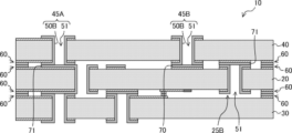
- FIG. 3 is a schematic cross-sectional view showing an example of the configuration of the quantum arithmetic device 10.
- FIG. FIG. 3 shows only the configuration around one quantum bit element 11 extracted.
- the quantum arithmetic device 10 has a structure in which a first substrate 30, a second substrate 40 and a third substrate 50 are laminated.
- the second substrate 30 is arranged on the bottom layer
- the third substrate 40 is arranged on the top layer
- the first substrate 20 is arranged on the intermediate layer between the top layer and the bottom layer.
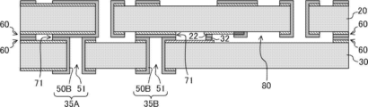
- FIG. 4 is an exploded view of the first substrate 20, the second substrate 30, and the third substrate 40 to facilitate understanding of the respective configurations of these substrates.
- a quantum bit element 11 is provided on the bottom surface of the first substrate 20 and a resonator 12 is provided on the top surface of the second substrate 30 .
- the resonator 12 is formed by patterning the conductive film 50A.
- the second substrate 30 is bonded to the lower surface side of the first substrate 20 via the seal member 60 so that the upper surface of the second substrate 30 faces the lower surface of the first substrate 20 .
- the qubit element 11 and the resonator 12 are connected to each other via a wire 21 and bumps 22 and 32 .
- the sealing member 60 includes a laminated film in which the conductive film 50A and the conductive film 50B are laminated.
- the wiring 21 is composed of a conductive film 50A, and the bumps 22 and 32 are each composed of a conductive film 50B.
- a control electrode 70 to which a control signal for controlling the quantum bit element 11 is supplied is provided on the upper surface of the first substrate 20 .
- the control electrode 70 is arranged directly above the qubit element 11 , and a control signal supplied to the control electrode 70 is transmitted to the qubit element 11 via the base material of the first substrate 20 .
- the third substrate 40 is bonded to the upper surface side of the first substrate 20 via the sealing member 60 so that the lower surface thereof faces the upper surface of the first substrate 20 .
- the first substrate 20 is provided with through vias 25A and 25B
- the second substrate 30 is provided with through vias 35A and 35B
- the third substrate 40 is provided with through vias 45A and 45B.
- These through vias each include a through hole 51 penetrating through the substrate and a conductive film 50B covering the inner wall of the through hole 51 .
- These through vias are electrically connected to electrodes 71 or control electrodes 70 provided on a substrate located on an adjacent layer.
- the control electrode 70 and the other electrodes 71 are each composed of a laminated film in which the conductive film 50A and the conductive film 50B are laminated.
- the through via 35A of the second substrate 30 functions as the ground port 14. That is, when the quantum arithmetic device 10 is used, as shown in FIG. 5A, the probe 300A fixed to the ground potential is brought into contact with the through via 35A. A ground potential supplied from the probe 300A is applied to each element provided on the upper and lower surfaces of the second substrate 30 through the through vias 35A. A ground potential is also applied to the resonator 12 .
- the through via 35A is electrically connected to the through via 25A of the first substrate 20, and the ground potential is applied to each element provided on the upper and lower surfaces of the first substrate 20. FIG. A ground potential is also applied to the qubit element 11 .
- the through via 25A is electrically connected to the through via 45A of the third substrate 40, and ground potential is applied to each element provided on the upper and lower surfaces of the third substrate 40.
- Both the through via 35A of the second substrate 30 and the through via 45A of the third substrate 40 may function as the ground port 14. That is, when using the quantum arithmetic device 10, as shown in FIG. 5B, the probes 300A fixed to the ground potential may be brought into contact with each of the through vias 35A and 45A.
- the through via 35B of the second substrate 30 is electrically connected to the resonator 12.
- the through via 35B functions as a readout port 13 for reading a bit signal indicating the state of the quantum bit element 11.
- FIG. That is, when the quantum arithmetic device 10 is used, as shown in FIGS. 5A and 5B, the probe 300B is brought into contact with the through via 35B, and the bit signal is extracted to the outside by the probe 300B.
- the through via 45B of the third substrate 40 is electrically connected to the control electrode 70 provided on the first substrate 20.
- the through via 45B functions as a control port 15 for controlling the qubit element 11 from the outside. That is, as shown in FIGS. 5A and 5B when the quantum arithmetic device 10 is used, the probe 300C is brought into contact with the through via 45B, and the control signal for controlling the quantum bit element 11 supplied from the probe 300C is It is supplied to the control electrode 70 through the through via 45B.
- the quantum arithmetic device 10 is used in a vacuum chamber at an extremely low temperature. Probes 300A, 300B, 300C can be housed inside a dilution refrigerator together with quantum computing device 10 .
- the through via 25B of the first substrate 20 is used as a gas introduction path for removing the protective film covering the surface of the quantum bit element 11 in the manufacturing process of the quantum arithmetic device 10.
- a manufacturing process of the quantum arithmetic device 10 will be described later.
- a space 80 is formed between the first substrate 20 and the second substrate 30 and between the first substrate 20 and the third substrate 40, respectively.
- a space 80 is also formed around the quantum bit element 11 .
- a through-hole 51 forming a through-via 25B of the first substrate 20 used as a gas introduction path communicates with a space 80 extending around the quantum bit element 11 .
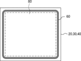
- FIG. 6A shows an example of the form of the sealing member 60 that forms the joint between the first substrate 20 and the second substrate 30 and the joint between the first substrate 20 and the third substrate 40.
- FIG. It is a top view.
- the sealing member 60 has a ring shape surrounding a space 80 formed between the substrates. By bonding the substrates together via the ring-shaped sealing member 60 surrounding the space 80 in this manner, the space 80 is sealed. Also, the opening ends of the through holes 51 forming the through vias 35A and 35B of the second substrate 30 are closed by the electrodes 71 provided on the lower surface of the first substrate 20. As shown in FIG.
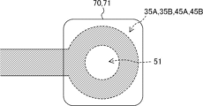
- FIG. FIG. 6B is a plan view showing a state in which the through holes 51 forming the through vias 35A, 35B, 45A, and 45B are closed with the electrodes 71 or the control electrodes 70, respectively.
- the opening ends of the through holes 51 forming the through vias 45A and 45B of the third substrate 40 and the through vias 35A and 35B of the second substrate 30 are connected to the electrodes 71 or the electrodes 71 provided on the first substrate 20.
- the space 80 is completely sealed by closing it with the control electrode 70 .
- the sealed space 80 is preferably a vacuum. By evacuating the space 80, adsorption of substances to the qubit element 11 can be suppressed without forming a protective film that causes dielectric loss on the surface of the qubit element 11. The surface can always be kept clean.
- the vacuum is not limited to a perfect vacuum, and includes a low-pressure state at which the effect of substantially suppressing adsorption of substances to the qubit element 11 is exhibited.
- the conductive films 50A and 50B constituting each element provided on the first to third substrates are made of a metal that exhibits superconductivity at a temperature equal to or lower than a predetermined temperature.
- TiN titanium nitride
- Al aluminum
- a method for manufacturing the quantum arithmetic device 10 will be described below. First, an example of a method for manufacturing the first substrate 20 will be described with reference to FIGS. 7 to 13. FIG.
- a base material 20a constituting the first substrate 20 is prepared.
- a silicon substrate can be used as the base material 20a (FIG. 7).
- a conductive film 50A is formed on each of the upper and lower surfaces of the substrate 20a by, for example, vapor deposition.
- TiN titanium nitride
- FIG. 8 the conductive film 50A
- FIG. 9 by patterning the conductive film 50A using a known photolithographic technique, the wiring 21 and the like are formed (FIG. 9).
- the superconducting Josephson element that constitutes the qubit element 11 is formed by, for example, a step of forming a first electrode (not shown) containing Al (aluminum) on the surface of the base material 20a by a vapor deposition method, and a first electrode using O 2 gas.
- the patterning of the first electrode and the second electrode may be performed, for example, by a lift-off method using a patterned resist (not shown).
- the opening pattern of the resist is a cross shape including a first linear portion along a first direction and a second linear portion along a second direction orthogonal to the first direction
- the first electrode may be formed in the portion corresponding to the first linear portion by performing the vapor deposition while tilting the first direction as the rotation axis.
- the second electrode may be formed in the portion corresponding to the second linear portion by performing the vapor deposition while tilting the rotation axis in the second direction. According to the above method, it is possible to pattern the first electrode and the second electrode with a single resist.
- a protective film 90 made of an insulator such as SiO 2 is formed on the surface of the substrate 20a by, for example, CVD (chemical vapor deposition).
- the qubit element 11 is covered with a protective film 90 .
- the protective film 90 is patterned using a known photolithographic technique. Protective film 90 is removed leaving a portion covering qubit element 11 (FIG. 11).
- a resist (not shown) is formed on the surface of the base material 20a, and this resist is patterned.
- through-holes 51 are formed in the base material 20a by deep RIE (Reactive Ion Etching), for example (FIG. 12).
- a conductive film 50B is formed on the upper and lower surfaces of the base material 20a by, for example, vapor deposition.
- the surface of the conductive film 50A and the inner wall of the through hole 51 are covered with the conductive film 50B.
- Al aluminum
- Patterning of the conductive film 50B is performed by, for example, a lift-off method (FIG. 13).
- a control electrode 70, other electrodes 71, a ring-shaped seal member 60, and the like are formed on the surface of the base material 20a.
- the through vias 25A and 25B are formed by covering the inner wall of the through hole 51 with the conductive film 50B.
- the first substrate 20 is completed through the above steps. Since the second substrate 30 and the third substrate 40 are manufactured in the same manner as the first substrate 20, the description of the manufacturing method of these substrates is omitted.
- FIG. 14 An example of a method of forming the quantum arithmetic device 10 by combining the first substrate 20, the second substrate 30 and the third substrate 40 will be described below with reference to FIGS. 14 to 18.
- FIG. 14 An example of a method of forming the quantum arithmetic device 10 by combining the first substrate 20, the second substrate 30 and the third substrate 40 will be described below with reference to FIGS. 14 to 18.
- FIG. 14 An example of a method of forming the quantum arithmetic device 10 by combining the first substrate 20, the second substrate 30 and the third substrate 40 will be described below with reference to FIGS. 14 to 18.
- the first substrate 20 and the second substrate 30 are placed in a vacuum chamber (not shown), and the lower surface of the first substrate 20 and the upper surface of the second substrate 30 are irradiated with an ion beam in the vacuum chamber ( Figure 14).
- elements that interfere with bonding such as oxide films, hydroxyl groups, and water molecules existing on the surface of the conductive film 50B forming the bonding portion between the first substrate 20 and the second substrate 30 are removed, and the conductive film is removed.
- the surface of 50B is activated.
- resist residues and adsorbed substances existing on the surfaces of the first substrate 20 and the second substrate 30 are removed, and the surfaces of the first substrate 20 and the second substrate 30 are cleaned.
- An inert gas such as argon is used for the ion beam. Since the quantum bit element 11 is covered with the protective film 90, damage to the quantum bit element 11 due to ion beam irradiation is suppressed.
- the first substrate 20 and the second substrate 30 are bonded together in a vacuum chamber. That is, the sealing member 60 of the first substrate 20 and the sealing member 60 of the second substrate 30 are bonded together, and the electrode 71 of the first substrate 20 and the through vias 35A and 35B of the second substrate 30 are bonded together. Then, the bumps 22 of the first substrate 20 and the bumps 32 of the second substrate 30 are bonded. Since the surface of the conductive film 50B constituting each of these elements is activated by ion beam irradiation, it is possible to obtain strong bonding at room temperature (approximately 25° C.). This technique is called surface activation room temperature bonding.
- the opening ends of the through holes 51 forming the through vias 35A and 35B of the second substrate 30 are closed by the electrodes 71 of the first substrate 20. As shown in FIG. The first substrate 20 and the second substrate 30 are joined with a gap therebetween, and a space 80 is formed around the quantum bit element 11 (FIG. 15).
- an etching gas such as vapor HF gas is introduced into the space 80 around the quantum bit element 11 through the through hole 51 forming the through via 25B of the first substrate 20 .
- an etching gas such as vapor HF gas is introduced into the space 80 around the quantum bit element 11 through the through hole 51 forming the through via 25B of the first substrate 20 .
- the protective film 90 covering the quantum bit element 11 is removed, and the silicon oxide film (SiO 2 ) formed on the surfaces of the first substrate 20 and the second substrate 30 is removed, thereby removing the first substrate.
- the surfaces of substrate 20 and second substrate 30 are cleaned (FIG. 16).
- the first substrate 20 and the second substrate 30 bonded together, and the third substrate 40 are placed in a vacuum chamber (not shown), and the upper surface of the first substrate 20 is placed in the vacuum chamber. And the lower surface of the third substrate 40 is irradiated with an ion beam (FIG. 17).
- elements that interfere with bonding such as oxide films, hydroxyl groups, and water molecules present on the surface of the conductive film 50B that forms the bonding portion between the first substrate 20 and the third substrate 40, are removed.
- the surface of 50B is activated. Further, resist residues and adsorbed substances existing on the surfaces of the first substrate 20 and the third substrate 40 are removed, and the surfaces of the first substrate 20 and the third substrate 40 are cleaned.
- the first substrate 20 and the third substrate 40 are bonded together in a vacuum chamber. That is, the sealing member 60 of the first substrate 20 and the sealing member 60 of the third substrate 40 are bonded, the electrode 71 of the first substrate 20 and the through via 45A of the third substrate are bonded, and the first The control electrode 70 of the substrate 20 and the through via 45B of the third substrate 40 are joined, and the through via 25B of the first substrate 20 and the electrode 71 of the third substrate 40 are joined (FIG. 18). Since the surface of the conductive film 50B constituting each of these elements is activated by ion beam irradiation, it is possible to obtain strong bonding at room temperature (approximately 25° C.).
- the through via 25B of the first substrate 20 is closed by the electrode 71 of the third substrate 40.
- FIG. Further, the through vias 45A and 45B of the third substrate 40 are closed by the electrodes 71 and the control electrodes 70 of the first substrate 20, respectively.
- the quantum arithmetic device 10 is completed through the above steps.
- the quantum arithmetic device 10 includes the first substrate 20 provided with the quantum bit element, the second substrate 30 laminated on the lower surface side of the first substrate 20, and It includes a third substrate 40 laminated to the top side of the first substrate 20 .
- the second substrate 30 arranged in the lowest layer is provided with a through via 35A functioning as the ground port 14 and a through via 35B functioning as the readout port 13 .
- through vias 45B functioning as control ports 15 are provided in the third substrate 40 arranged in the uppermost layer.
- the through via 45A of the third substrate 40 can also be used as the ground port 14.
- FIG. These through vias 35A, 35B, 45A and 45B are each electrically connected to the first substrate 20 arranged in the intermediate layer.
- the probes 300A to 300C are brought into contact with these through vias 35A, 35B, 45A and 45B, thereby including the quantum bit element 11 and the resonator 12. It becomes possible to access the quantum arithmetic circuit.
- the number of required probes increases as the number of bits of the quantum arithmetic device 10 increases. As the number of bits increases and the size of the quantum arithmetic device 10 progresses, the density of ports increases, and the density of probes increases accordingly. As a result, contact failure between each port and the probe may occur, or signal crosstalk may occur between the ports.
- the time during which the quantum operation can be continued in the qubit element 11 is called coherence time.
- the coherence time is sensitively affected by the surrounding conditions of the qubit element 11 . For example, if a dielectric such as an oxide film exists around the qubit element 11, the coherence time is shortened due to dielectric loss. Therefore, it is preferable not to form an insulating film such as a protective film on the surface of the quantum bit element 11 .
- the quantum arithmetic device 10 is kept at an extremely low temperature in the vacuum chamber, but the adsorbed substances that cause decoherence that are adsorbed in the atmosphere are cooled and remain as they are.
- the surface of the qubit element 11 must be kept clean at all times because the coherence time is shortened by the adsorbed substances adsorbed on the surface of the qubit element 11 .
- the space 80 formed around the quantum bit element 11 is in a vacuum-sealed state. As a result, adsorption of substances to the qubit element 11 can be suppressed without forming a protective film that causes dielectric loss on the surface of the qubit element 11, and the surface of the qubit element 11 is always kept clean. can keep.
- the characteristics of the superconducting Josephson element 201 that constitutes the qubit element 11 may change due to heating.
- the bonding between the first substrate 20 and the second substrate 30 and the bonding between the first substrate 20 and the third substrate 40 are performed on the surface Activation is performed by room temperature bonding. Therefore, it is possible to avoid characteristic fluctuations due to heating of the quantum bit element 11 .
- the surface of each substrate is irradiated with an ion beam.
- the quantum bit element 11 is covered with the protective film 90 during ion beam irradiation. As a result, damage to the quantum bit element 11 due to ion beam irradiation can be suppressed.
- the protective film 90 covering the quantum bit element 11 is removed after bonding the first substrate 20 and the second substrate 30 together. This makes it possible to eliminate factors that reduce the coherence time.
- the protective film 90 is removed after the first substrate 20 and the second substrate 30 are bonded together.
- the etching gas is introduced from the through hole 51 communicating with the space 80 where the etching is performed. This makes it possible to efficiently remove the protective film 90 and clean the surfaces of the first substrate 20 and the second substrate 30 .
- FIG. 19 is a schematic cross-sectional view showing an example of the configuration of a quantum processing device 10A having a two-layer structure.
- the quantum arithmetic device 10A differs from the quantum arithmetic device 10 shown in FIG. 3 and the like in that it does not have the third substrate 40 . That is, in the quantum processing device 10A, the first substrate 20 is arranged in the uppermost layer, the control electrode 70 functions as the control port 15, and the probe 300C is brought into contact with the control electrode 70.
- the space 80 around the quantum bit element 11 is open to the atmosphere through the through hole 51 forming the through via 25B.
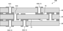
- FIG. 20 is a schematic cross-sectional view showing an example of the configuration of a quantum arithmetic device 10B in which the qubit element 11 and the resonator 12 are provided on the first substrate 20. As shown in FIG.
- the through via having the through hole 51 communicating with the space 80 around the quantum bit element 11 is provided in the first substrate 20.
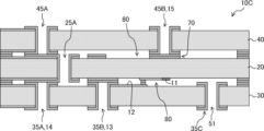
- Through vias having 51 may be provided in a substrate other than the first substrate 20 .
- a through hole 51 forming a through via 35C provided in the second substrate 30 may communicate with a space 80 around the quantum bit element 11. .
- the quantum arithmetic device 10D shown in FIG. The ends may be closed by electrodes 71 of the third substrate 40 .
- the through vias 25A of the first substrate 20 arranged on the uppermost layer and the through vias 45A of the third substrate 40 arranged on the lowermost layer function as the ground ports 14, respectively.
- a through via 45B of the third substrate 40 arranged in the bottom layer functions as the read port 13 .
- the control electrode 70 of the first substrate 20 arranged on the top layer functions as the control port 15 .
- FIG. 22 is a schematic cross-sectional view showing an example of the configuration of a quantum arithmetic device 10E according to the second embodiment of technology disclosed herein.
- the second substrate 30 arranged in the layer adjacent to the first substrate 20 on which the quantum bit element 11 is provided in the quantum arithmetic device 10E has the thickness of the second substrate 30 at the portion facing the quantum bit element 11. It has a concave portion 95A that is recessed in the vertical direction.
- the first substrate 20 arranged in a layer adjacent to the second substrate 30 provided with the resonator 12 is recessed in the thickness direction of the first substrate 20 at a portion facing the resonator 12. It has a recess 95B.
- the surfaces of the recesses 95A and 95B are covered with the conductive film 50B.
- the second substrate 30 has the concave portion 95A, so that capacitive coupling between the qubit element 11 and the second substrate 30 can be suppressed.
- the first substrate 20 has the concave portion 95B, capacitive coupling between the resonator 12 and the first substrate 20 can be suppressed. Thereby, the operations of the qubit element 11 and the resonator 12 can be stabilized.
- the concave portions 95A and 95B with the conductive film 50B, external noise that affects the operation of the qubit element 11 and the resonator 12 is suppressed and radiated from the qubit element 11 and the resonator 12. It is possible to suppress diffusion of electromagnetic noise.
- control port 20 first substrate 25A, 25B through via 30 second substrate 35A, 35B, 35C Through via 40 Third substrate 45A, 45B Through via 50A, 50B Conductive film 51 Through hole 60 Seal member 70 Control electrode 71 Electrode 80 Space 90 Protective film 95A, 95B Concave portion
Landscapes
- Engineering & Computer Science (AREA)
- Physics & Mathematics (AREA)
- Theoretical Computer Science (AREA)
- General Physics & Mathematics (AREA)
- Data Mining & Analysis (AREA)
- Computing Systems (AREA)
- Evolutionary Computation (AREA)
- Computational Mathematics (AREA)
- Mathematical Analysis (AREA)
- Mathematical Optimization (AREA)
- Pure & Applied Mathematics (AREA)
- Condensed Matter Physics & Semiconductors (AREA)
- General Engineering & Computer Science (AREA)
- Mathematical Physics (AREA)
- Software Systems (AREA)
- Artificial Intelligence (AREA)
- Superconductor Devices And Manufacturing Methods Thereof (AREA)
- Photovoltaic Devices (AREA)
- Recrystallisation Techniques (AREA)
- Semiconductor Memories (AREA)
Priority Applications (4)
| Application Number | Priority Date | Filing Date | Title |
|---|---|---|---|
| EP22918653.1A EP4475177A4 (en) | 2022-01-07 | 2022-01-07 | QUANTUM COMPUTING DEVICE AND METHOD FOR MANUFACTURING QUANTUM COMPUTING DEVICE |
| PCT/JP2022/000385 WO2023132064A1 (ja) | 2022-01-07 | 2022-01-07 | 量子演算装置及び量子演算装置の製造方法 |
| JP2023572320A JP7666653B2 (ja) | 2022-01-07 | 2022-01-07 | 量子演算装置及び量子演算装置の製造方法 |
| EP26150016.9A EP4730215A3 (en) | 2022-01-07 | 2022-01-07 | Method for manufacturing quantum computing apparatus |
Applications Claiming Priority (1)
| Application Number | Priority Date | Filing Date | Title |
|---|---|---|---|
| PCT/JP2022/000385 WO2023132064A1 (ja) | 2022-01-07 | 2022-01-07 | 量子演算装置及び量子演算装置の製造方法 |
Publications (1)
| Publication Number | Publication Date |
|---|---|
| WO2023132064A1 true WO2023132064A1 (ja) | 2023-07-13 |
Family
ID=87073573
Family Applications (1)
| Application Number | Title | Priority Date | Filing Date |
|---|---|---|---|
| PCT/JP2022/000385 Ceased WO2023132064A1 (ja) | 2022-01-07 | 2022-01-07 | 量子演算装置及び量子演算装置の製造方法 |
Country Status (3)
| Country | Link |
|---|---|
| EP (2) | EP4730215A3 (https=) |
| JP (1) | JP7666653B2 (https=) |
| WO (1) | WO2023132064A1 (https=) |
Cited By (1)
| Publication number | Priority date | Publication date | Assignee | Title |
|---|---|---|---|---|
| WO2025046715A1 (ja) * | 2023-08-28 | 2025-03-06 | 富士通株式会社 | 量子ビットデバイス及び量子ビットデバイスの製造方法 |
Citations (7)
| Publication number | Priority date | Publication date | Assignee | Title |
|---|---|---|---|---|
| JPH04338683A (ja) * | 1991-05-16 | 1992-11-25 | Fujitsu Ltd | 超伝導集積回路素子とその実装方法 |
| JPH11177157A (ja) * | 1997-12-08 | 1999-07-02 | Agency Of Ind Science & Technol | 超電導集積回路構造及びその製造方法 |
| US20180013052A1 (en) * | 2015-07-23 | 2018-01-11 | Massachusetts Institute Of Technology | Qubit and Coupler Circuit Structures and Coupling Techniques |
| US20190287946A1 (en) | 2017-11-28 | 2019-09-19 | International Business Machines Corporation | Signal routing in complex quantum systems |
| JP2019532505A (ja) * | 2016-09-13 | 2019-11-07 | グーグル エルエルシー | 積層量子デバイス内の損失の低減 |
| US20200259064A1 (en) | 2019-02-11 | 2020-08-13 | International Business Machines Corporation | Cold-welded flip chip interconnect structure |
| JP2021072351A (ja) * | 2019-10-30 | 2021-05-06 | 日本電気株式会社 | 超伝導回路装置、スペーサ、及び超伝導回路装置の製造方法 |
Family Cites Families (4)
| Publication number | Priority date | Publication date | Assignee | Title |
|---|---|---|---|---|
| US9836699B1 (en) * | 2015-04-27 | 2017-12-05 | Rigetti & Co. | Microwave integrated quantum circuits with interposer |
| WO2017155531A1 (en) * | 2016-03-10 | 2017-09-14 | Technische Universiteit Delft | Superconducting microwave-frequency vias for mult-planar quantum circuits |
| US10804399B2 (en) * | 2016-09-24 | 2020-10-13 | Intel Corporation | Double-sided quantum dot devices |
| WO2019059879A1 (en) * | 2017-09-19 | 2019-03-28 | Google Llc | PILLARS AS FALLS FOR PRECISE CHIP CHIP SEPARATION |
-
2022
- 2022-01-07 EP EP26150016.9A patent/EP4730215A3/en active Pending
- 2022-01-07 JP JP2023572320A patent/JP7666653B2/ja active Active
- 2022-01-07 EP EP22918653.1A patent/EP4475177A4/en active Pending
- 2022-01-07 WO PCT/JP2022/000385 patent/WO2023132064A1/ja not_active Ceased
Patent Citations (7)
| Publication number | Priority date | Publication date | Assignee | Title |
|---|---|---|---|---|
| JPH04338683A (ja) * | 1991-05-16 | 1992-11-25 | Fujitsu Ltd | 超伝導集積回路素子とその実装方法 |
| JPH11177157A (ja) * | 1997-12-08 | 1999-07-02 | Agency Of Ind Science & Technol | 超電導集積回路構造及びその製造方法 |
| US20180013052A1 (en) * | 2015-07-23 | 2018-01-11 | Massachusetts Institute Of Technology | Qubit and Coupler Circuit Structures and Coupling Techniques |
| JP2019532505A (ja) * | 2016-09-13 | 2019-11-07 | グーグル エルエルシー | 積層量子デバイス内の損失の低減 |
| US20190287946A1 (en) | 2017-11-28 | 2019-09-19 | International Business Machines Corporation | Signal routing in complex quantum systems |
| US20200259064A1 (en) | 2019-02-11 | 2020-08-13 | International Business Machines Corporation | Cold-welded flip chip interconnect structure |
| JP2021072351A (ja) * | 2019-10-30 | 2021-05-06 | 日本電気株式会社 | 超伝導回路装置、スペーサ、及び超伝導回路装置の製造方法 |
Non-Patent Citations (1)
| Title |
|---|
| See also references of EP4475177A4 |
Cited By (1)
| Publication number | Priority date | Publication date | Assignee | Title |
|---|---|---|---|---|
| WO2025046715A1 (ja) * | 2023-08-28 | 2025-03-06 | 富士通株式会社 | 量子ビットデバイス及び量子ビットデバイスの製造方法 |
Also Published As
| Publication number | Publication date |
|---|---|
| JPWO2023132064A1 (https=) | 2023-07-13 |
| EP4475177A4 (en) | 2025-07-16 |
| EP4730215A3 (en) | 2026-05-06 |
| EP4475177A1 (en) | 2024-12-11 |
| JP7666653B2 (ja) | 2025-04-22 |
| EP4730215A2 (en) | 2026-04-22 |
Similar Documents
| Publication | Publication Date | Title |
|---|---|---|
| US12518977B2 (en) | Signal distribution for a quantum computing system | |
| JP7819759B2 (ja) | 量子デバイス及び量子デバイスの製造方法 | |
| JP2020522120A (ja) | 正確なチップ間分離のためのストッパとしてのピラー | |
| US20260082822A1 (en) | Quantum operation device and method of manufacturing quantum operation device | |
| WO2023132064A1 (ja) | 量子演算装置及び量子演算装置の製造方法 | |
| WO2022118463A1 (ja) | 量子デバイス及びその製造方法 | |
| EP4703979A1 (en) | Quantum computing device and method for manufacturing quantum computing device | |
| WO2023139779A1 (ja) | ジョセフソン素子、超伝導回路、量子演算装置及びジョセフソン素子の製造方法 | |
| WO2022118464A1 (ja) | 量子デバイス及びその製造方法 | |
| US20260068537A1 (en) | Quantum bit device and method for manufacturing quantum bit device | |
| JP7528564B2 (ja) | 量子デバイス及びその製造方法 | |
| WO2024111061A1 (ja) | 装置および装置の製造方法 | |
| US20260068539A1 (en) | Quantum bit device and method for manufacturing quantum bit device | |
| EP4703980A1 (en) | Quantum bit device and method for manufacturing quantum bit device | |
| US20250200415A1 (en) | Qubit device and qubit device fabrication method | |
| EP4712751A1 (en) | Qubit device and method of manufacturing qubit device | |
| KR102910435B1 (ko) | 초전도 양자큐비트 소자 및 그 제조방법 | |
| US20250169380A1 (en) | Qubit chip device and method of manufacturing the same | |
| US20250301921A1 (en) | Device and method of manufacturing device | |
| US20250309092A1 (en) | Device and method of manufacturing device | |
| US20250301919A1 (en) | Method of manufacturing a superconducting integrated circuit device | |
| WO2025046715A1 (ja) | 量子ビットデバイス及び量子ビットデバイスの製造方法 | |
| JPS6151940A (ja) | 半導体装置の配線構造 | |
| KR20240117866A (ko) | 조셉슨 접합 소자, 조셉슨 접합 소자를 포함하는 초전도 큐비트, 및 조셉슨 접합 소자의 제조 방법 | |
| WO2024185131A1 (ja) | 量子デバイス及び量子デバイスの製造方法 |
Legal Events
| Date | Code | Title | Description |
|---|---|---|---|
| ENP | Entry into the national phase |
Ref document number: 2023572320 Country of ref document: JP Kind code of ref document: A |
|
| WWE | Wipo information: entry into national phase |
Ref document number: 2022918653 Country of ref document: EP |
|
| NENP | Non-entry into the national phase |
Ref country code: DE |
|
| ENP | Entry into the national phase |
Ref document number: 2022918653 Country of ref document: EP Effective date: 20240807 |
|
| 121 | Ep: the epo has been informed by wipo that ep was designated in this application |
Ref document number: 22918653 Country of ref document: EP Kind code of ref document: A1 |
|
| 121 | Ep: the epo has been informed by wipo that ep was designated in this application |
Ref document number: 22918653 Country of ref document: EP Kind code of ref document: A1 |