WO2023127954A1 - 記録媒体、カード、冊子、画像認証システムおよび画像認証方法 - Google Patents
記録媒体、カード、冊子、画像認証システムおよび画像認証方法 Download PDFInfo
- Publication number
- WO2023127954A1 WO2023127954A1 PCT/JP2022/048603 JP2022048603W WO2023127954A1 WO 2023127954 A1 WO2023127954 A1 WO 2023127954A1 JP 2022048603 W JP2022048603 W JP 2022048603W WO 2023127954 A1 WO2023127954 A1 WO 2023127954A1
- Authority
- WO
- WIPO (PCT)
- Prior art keywords
- image
- layer
- recording medium
- recording
- recording layer
- Prior art date
- Legal status (The legal status is an assumption and is not a legal conclusion. Google has not performed a legal analysis and makes no representation as to the accuracy of the status listed.)
- Ceased
Links
Images








Classifications
-
- B—PERFORMING OPERATIONS; TRANSPORTING
- B42—BOOKBINDING; ALBUMS; FILES; SPECIAL PRINTED MATTER
- B42D—BOOKS; BOOK COVERS; LOOSE LEAVES; PRINTED MATTER CHARACTERISED BY IDENTIFICATION OR SECURITY FEATURES; PRINTED MATTER OF SPECIAL FORMAT OR STYLE NOT OTHERWISE PROVIDED FOR; DEVICES FOR USE THEREWITH AND NOT OTHERWISE PROVIDED FOR; MOVABLE-STRIP WRITING OR READING APPARATUS
- B42D25/00—Information-bearing cards or sheet-like structures characterised by identification or security features; Manufacture thereof
- B42D25/30—Identification or security features, e.g. for preventing forgery
- B42D25/36—Identification or security features, e.g. for preventing forgery comprising special materials
- B42D25/378—Special inks
-
- B—PERFORMING OPERATIONS; TRANSPORTING
- B41—PRINTING; LINING MACHINES; TYPEWRITERS; STAMPS
- B41M—PRINTING, DUPLICATING, MARKING, OR COPYING PROCESSES; COLOUR PRINTING
- B41M5/00—Duplicating or marking methods; Sheet materials for use therein
- B41M5/26—Thermography ; Marking by high energetic means, e.g. laser otherwise than by burning, and characterised by the material used
- B41M5/34—Multicolour thermography
-
- B—PERFORMING OPERATIONS; TRANSPORTING
- B42—BOOKBINDING; ALBUMS; FILES; SPECIAL PRINTED MATTER
- B42D—BOOKS; BOOK COVERS; LOOSE LEAVES; PRINTED MATTER CHARACTERISED BY IDENTIFICATION OR SECURITY FEATURES; PRINTED MATTER OF SPECIAL FORMAT OR STYLE NOT OTHERWISE PROVIDED FOR; DEVICES FOR USE THEREWITH AND NOT OTHERWISE PROVIDED FOR; MOVABLE-STRIP WRITING OR READING APPARATUS
- B42D25/00—Information-bearing cards or sheet-like structures characterised by identification or security features; Manufacture thereof
-
- B—PERFORMING OPERATIONS; TRANSPORTING
- B42—BOOKBINDING; ALBUMS; FILES; SPECIAL PRINTED MATTER
- B42D—BOOKS; BOOK COVERS; LOOSE LEAVES; PRINTED MATTER CHARACTERISED BY IDENTIFICATION OR SECURITY FEATURES; PRINTED MATTER OF SPECIAL FORMAT OR STYLE NOT OTHERWISE PROVIDED FOR; DEVICES FOR USE THEREWITH AND NOT OTHERWISE PROVIDED FOR; MOVABLE-STRIP WRITING OR READING APPARATUS
- B42D25/00—Information-bearing cards or sheet-like structures characterised by identification or security features; Manufacture thereof
- B42D25/20—Information-bearing cards or sheet-like structures characterised by identification or security features; Manufacture thereof characterised by a particular use or purpose
- B42D25/23—Identity cards
-
- B—PERFORMING OPERATIONS; TRANSPORTING
- B42—BOOKBINDING; ALBUMS; FILES; SPECIAL PRINTED MATTER
- B42D—BOOKS; BOOK COVERS; LOOSE LEAVES; PRINTED MATTER CHARACTERISED BY IDENTIFICATION OR SECURITY FEATURES; PRINTED MATTER OF SPECIAL FORMAT OR STYLE NOT OTHERWISE PROVIDED FOR; DEVICES FOR USE THEREWITH AND NOT OTHERWISE PROVIDED FOR; MOVABLE-STRIP WRITING OR READING APPARATUS
- B42D25/00—Information-bearing cards or sheet-like structures characterised by identification or security features; Manufacture thereof
- B42D25/20—Information-bearing cards or sheet-like structures characterised by identification or security features; Manufacture thereof characterised by a particular use or purpose
- B42D25/24—Passports
-
- B—PERFORMING OPERATIONS; TRANSPORTING
- B42—BOOKBINDING; ALBUMS; FILES; SPECIAL PRINTED MATTER
- B42D—BOOKS; BOOK COVERS; LOOSE LEAVES; PRINTED MATTER CHARACTERISED BY IDENTIFICATION OR SECURITY FEATURES; PRINTED MATTER OF SPECIAL FORMAT OR STYLE NOT OTHERWISE PROVIDED FOR; DEVICES FOR USE THEREWITH AND NOT OTHERWISE PROVIDED FOR; MOVABLE-STRIP WRITING OR READING APPARATUS
- B42D25/00—Information-bearing cards or sheet-like structures characterised by identification or security features; Manufacture thereof
- B42D25/30—Identification or security features, e.g. for preventing forgery
- B42D25/324—Reliefs
-
- B—PERFORMING OPERATIONS; TRANSPORTING
- B42—BOOKBINDING; ALBUMS; FILES; SPECIAL PRINTED MATTER
- B42D—BOOKS; BOOK COVERS; LOOSE LEAVES; PRINTED MATTER CHARACTERISED BY IDENTIFICATION OR SECURITY FEATURES; PRINTED MATTER OF SPECIAL FORMAT OR STYLE NOT OTHERWISE PROVIDED FOR; DEVICES FOR USE THEREWITH AND NOT OTHERWISE PROVIDED FOR; MOVABLE-STRIP WRITING OR READING APPARATUS
- B42D25/00—Information-bearing cards or sheet-like structures characterised by identification or security features; Manufacture thereof
- B42D25/30—Identification or security features, e.g. for preventing forgery
- B42D25/328—Diffraction gratings; Holograms
-
- B—PERFORMING OPERATIONS; TRANSPORTING
- B42—BOOKBINDING; ALBUMS; FILES; SPECIAL PRINTED MATTER
- B42D—BOOKS; BOOK COVERS; LOOSE LEAVES; PRINTED MATTER CHARACTERISED BY IDENTIFICATION OR SECURITY FEATURES; PRINTED MATTER OF SPECIAL FORMAT OR STYLE NOT OTHERWISE PROVIDED FOR; DEVICES FOR USE THEREWITH AND NOT OTHERWISE PROVIDED FOR; MOVABLE-STRIP WRITING OR READING APPARATUS
- B42D25/00—Information-bearing cards or sheet-like structures characterised by identification or security features; Manufacture thereof
- B42D25/30—Identification or security features, e.g. for preventing forgery
- B42D25/351—Translucent or partly translucent parts, e.g. windows
-
- B—PERFORMING OPERATIONS; TRANSPORTING
- B42—BOOKBINDING; ALBUMS; FILES; SPECIAL PRINTED MATTER
- B42D—BOOKS; BOOK COVERS; LOOSE LEAVES; PRINTED MATTER CHARACTERISED BY IDENTIFICATION OR SECURITY FEATURES; PRINTED MATTER OF SPECIAL FORMAT OR STYLE NOT OTHERWISE PROVIDED FOR; DEVICES FOR USE THEREWITH AND NOT OTHERWISE PROVIDED FOR; MOVABLE-STRIP WRITING OR READING APPARATUS
- B42D25/00—Information-bearing cards or sheet-like structures characterised by identification or security features; Manufacture thereof
- B42D25/30—Identification or security features, e.g. for preventing forgery
- B42D25/36—Identification or security features, e.g. for preventing forgery comprising special materials
-
- B—PERFORMING OPERATIONS; TRANSPORTING
- B42—BOOKBINDING; ALBUMS; FILES; SPECIAL PRINTED MATTER
- B42D—BOOKS; BOOK COVERS; LOOSE LEAVES; PRINTED MATTER CHARACTERISED BY IDENTIFICATION OR SECURITY FEATURES; PRINTED MATTER OF SPECIAL FORMAT OR STYLE NOT OTHERWISE PROVIDED FOR; DEVICES FOR USE THEREWITH AND NOT OTHERWISE PROVIDED FOR; MOVABLE-STRIP WRITING OR READING APPARATUS
- B42D25/00—Information-bearing cards or sheet-like structures characterised by identification or security features; Manufacture thereof
- B42D25/40—Manufacture
- B42D25/405—Marking
- B42D25/41—Marking using electromagnetic radiation
-
- B—PERFORMING OPERATIONS; TRANSPORTING
- B42—BOOKBINDING; ALBUMS; FILES; SPECIAL PRINTED MATTER
- B42D—BOOKS; BOOK COVERS; LOOSE LEAVES; PRINTED MATTER CHARACTERISED BY IDENTIFICATION OR SECURITY FEATURES; PRINTED MATTER OF SPECIAL FORMAT OR STYLE NOT OTHERWISE PROVIDED FOR; DEVICES FOR USE THEREWITH AND NOT OTHERWISE PROVIDED FOR; MOVABLE-STRIP WRITING OR READING APPARATUS
- B42D25/00—Information-bearing cards or sheet-like structures characterised by identification or security features; Manufacture thereof
- B42D25/40—Manufacture
- B42D25/45—Associating two or more layers
-
- B—PERFORMING OPERATIONS; TRANSPORTING
- B42—BOOKBINDING; ALBUMS; FILES; SPECIAL PRINTED MATTER
- B42D—BOOKS; BOOK COVERS; LOOSE LEAVES; PRINTED MATTER CHARACTERISED BY IDENTIFICATION OR SECURITY FEATURES; PRINTED MATTER OF SPECIAL FORMAT OR STYLE NOT OTHERWISE PROVIDED FOR; DEVICES FOR USE THEREWITH AND NOT OTHERWISE PROVIDED FOR; MOVABLE-STRIP WRITING OR READING APPARATUS
- B42D25/00—Information-bearing cards or sheet-like structures characterised by identification or security features; Manufacture thereof
- B42D25/40—Manufacture
- B42D25/45—Associating two or more layers
- B42D25/46—Associating two or more layers using pressure
-
- B—PERFORMING OPERATIONS; TRANSPORTING
- B41—PRINTING; LINING MACHINES; TYPEWRITERS; STAMPS
- B41M—PRINTING, DUPLICATING, MARKING, OR COPYING PROCESSES; COLOUR PRINTING
- B41M2205/00—Printing methods or features related to printing methods; Location or type of the layers
- B41M2205/04—Direct thermal recording [DTR]
-
- B—PERFORMING OPERATIONS; TRANSPORTING
- B41—PRINTING; LINING MACHINES; TYPEWRITERS; STAMPS
- B41M—PRINTING, DUPLICATING, MARKING, OR COPYING PROCESSES; COLOUR PRINTING
- B41M2205/00—Printing methods or features related to printing methods; Location or type of the layers
- B41M2205/38—Intermediate layers; Layers between substrate and imaging layer
-
- B—PERFORMING OPERATIONS; TRANSPORTING
- B41—PRINTING; LINING MACHINES; TYPEWRITERS; STAMPS
- B41M—PRINTING, DUPLICATING, MARKING, OR COPYING PROCESSES; COLOUR PRINTING
- B41M2205/00—Printing methods or features related to printing methods; Location or type of the layers
- B41M2205/42—Multiple imaging layers
-
- B—PERFORMING OPERATIONS; TRANSPORTING
- B41—PRINTING; LINING MACHINES; TYPEWRITERS; STAMPS
- B41M—PRINTING, DUPLICATING, MARKING, OR COPYING PROCESSES; COLOUR PRINTING
- B41M5/00—Duplicating or marking methods; Sheet materials for use therein
- B41M5/26—Thermography ; Marking by high energetic means, e.g. laser otherwise than by burning, and characterised by the material used
- B41M5/40—Thermography ; Marking by high energetic means, e.g. laser otherwise than by burning, and characterised by the material used characterised by the base backcoat, intermediate, or covering layers, e.g. for thermal transfer dye-donor or dye-receiver sheets; Heat, radiation filtering or absorbing means or layers; combined with other image registration layers or compositions; Special originals for reproduction by thermography
- B41M5/42—Intermediate, backcoat, or covering layers
-
- B—PERFORMING OPERATIONS; TRANSPORTING
- B41—PRINTING; LINING MACHINES; TYPEWRITERS; STAMPS
- B41M—PRINTING, DUPLICATING, MARKING, OR COPYING PROCESSES; COLOUR PRINTING
- B41M5/00—Duplicating or marking methods; Sheet materials for use therein
- B41M5/26—Thermography ; Marking by high energetic means, e.g. laser otherwise than by burning, and characterised by the material used
- B41M5/40—Thermography ; Marking by high energetic means, e.g. laser otherwise than by burning, and characterised by the material used characterised by the base backcoat, intermediate, or covering layers, e.g. for thermal transfer dye-donor or dye-receiver sheets; Heat, radiation filtering or absorbing means or layers; combined with other image registration layers or compositions; Special originals for reproduction by thermography
- B41M5/46—Thermography ; Marking by high energetic means, e.g. laser otherwise than by burning, and characterised by the material used characterised by the base backcoat, intermediate, or covering layers, e.g. for thermal transfer dye-donor or dye-receiver sheets; Heat, radiation filtering or absorbing means or layers; combined with other image registration layers or compositions; Special originals for reproduction by thermography characterised by the light-to-heat converting means; characterised by the heat or radiation filtering or absorbing means or layers
Definitions
- the present disclosure relates to recording media, cards, booklets, image authentication systems, and image authentication methods.
- an upper base material and a lower base material are laminated so as to be the front surface and the back surface, and adhesive layers 1 and 2 are laminated adjacently inside each base material of the upper base material and the lower base material. and at least two or more thermosensitive recording layers are laminated between the adhesive layer 1 and the adhesive layer 2, and a release layer is provided between two adjacent thermosensitive recording layers. Labels are disclosed. In addition, when the multilayer thermosensitive label having the above structure is attached to an adherend as a sealing label and then opened, the label is peeled off from the release layer, and the label is separated into two parts, namely the envelope body and the flap. It is disclosed that high security can be obtained because the form remains.
- Patent Literature 1 does not describe a technique that enables authenticity determination of a recording medium (multilayer thermosensitive label).
- the purpose of the present disclosure is to provide a recording medium, card, booklet, image authentication system, and image authentication method capable of authenticity determination.
- the recording medium of the present disclosure is comprising a substrate and a recording layer,
- the recording layer has an irregular surface composed of random irregularities, and contains an electron-donating color former, an electron-accepting color developer, and a matrix resin.
- the card of the present disclosure includes the recording medium of the present disclosure.
- the booklet of the present disclosure includes the recording medium of the present disclosure.
- the image authentication system of the present disclosure is comprising a first terminal device, a second terminal device, and an image authentication device
- the first terminal device draws an image on a first recording medium having a recording layer having an uneven surface formed of random unevenness by an image drawing device, and then focuses on the recording layer of the first recording medium. acquire a first image by imaging a partial area of the first recording medium with a first imaging device, and send the first image to the image authentication device;
- a second terminal device focuses on a recording layer having an irregular surface composed of random irregularities, and captures an image of a partial area of a second recording medium including the recording layer with a second imaging device. obtaining a second image and sending it to an image authentication device;
- the image authentication device compares the first image received from the first terminal device with the second image received from the second terminal device, and notifies the result of the comparison to the second terminal device.
- the image authentication method of the present disclosure includes: After the first terminal device draws an image with the image drawing device on the first recording medium provided with the recording layer having an uneven surface composed of random unevenness, the recording layer of the first recording medium is focused. capturing a partial area of a first recording medium with a first imaging device to obtain a first image, and transmitting the first image to an image authentication device; A second terminal device focuses on a recording layer having an uneven surface composed of random unevenness, and captures an image of a partial area of a second recording medium having the recording layer with a second imaging device. obtaining a second image and sending it to the image authentication device; The image authentication device compares the first image received from the first terminal device with the second image received from the second terminal device, and notifies the second terminal device of the result of the comparison. Prepare.
- FIG. 1 is a plan view showing an example of the appearance of a recording medium according to the first embodiment.
- FIG. 2 is a cross-sectional view showing an example of the configuration of the recording medium according to the first embodiment.
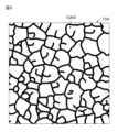
- FIG. 3 is a plan view showing an example of the surface shape of the recording layer in an unrecorded state.
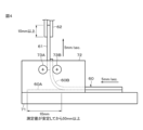
- FIG. 4 is a diagram of a test apparatus for a 90 degree peel test.
- FIG. 5 is a cross-sectional view showing the configuration of a recording medium according to a reference example.
- FIG. 6 is a diagram showing an example of an observed image when the recording layer of the recording medium according to the first embodiment is focused.
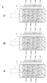
- 7A is a cross-sectional view showing a first example of the configuration of a recording medium according to Modification 1.
- FIG. 1 is a plan view showing an example of the appearance of a recording medium according to the first embodiment.
- FIG. 2 is a cross-sectional view showing an example of the configuration of the recording medium according to the first embodiment.
- FIG. 7B is a cross-sectional view showing a second example of the configuration of the recording medium according to Modification 1.
- FIG. 7C is a cross-sectional view showing a third example of the configuration of the recording medium according to Modification 1.
- FIG. 8A is a cross-sectional view showing a fourth example of the configuration of a recording medium according to modification 1.
- FIG. 8B is a cross-sectional view showing a fifth example of the configuration of the recording medium according to Modification 1.
- FIG. 8C is a cross-sectional view showing a sixth example of the configuration of the recording medium according to Modification 1.
- FIG. FIG. 9 is a cross-sectional view showing an example of the configuration of a recording medium according to Modification 2. As shown in FIG. FIG.
- FIG. 10A is a plan view showing an example of the appearance of a card according to the second embodiment
- FIG. 10B is a cross-sectional view along line XB-XB of FIG. 10A
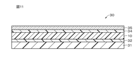
- 11 is a cross-sectional view showing an example of the configuration of a card according to Modification 1.
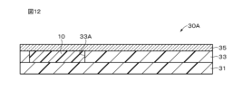
- FIG. FIG. 12 is a cross-sectional view showing an example of the configuration of a card according to the third embodiment.
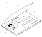
- FIG. 13 is a perspective view showing an example of the appearance of a booklet according to the fourth embodiment.
- FIG. 14 is a diagram showing an example of the configuration of an image authentication system according to the fifth embodiment.
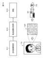
- FIG. 15 is a diagram for explaining an example of the image registration operation of the image authentication system according to the fifth embodiment.
- FIG. 16 is a diagram for explaining an example of image authentication operation of the image authentication system according to the fifth embodiment.
- FIG. 1 is a plan view showing an example of the appearance of a recording medium 10 according to the first embodiment.
- the recording medium 10 is, for example, a recording medium for cards or passports, and a face photograph is drawn on the recording medium 10 .
- the recording medium 10 is configured to be able to change its coloring state by laser light irradiation (external stimulus).
- An image can be drawn on the recording medium 10 by this change in coloring state.
- the image is a photograph of the face will be described, but the image may be a photograph other than the photograph of the face.
- the image is not limited to a photograph, and may be a pattern, a color pattern, or the like, or may be text such as characters or symbols.
- the image may be composed of a combination of two or more of photographs, designs, colors and texts.
- the laser light is preferably near-infrared laser light.
- near-infrared laser light refers to laser light having a peak wavelength in a wavelength range of more than 780 nm and less than or equal to 2.5 ⁇ m.
- the change in coloring state may be a reversible change or an irreversible change. That is, the system of the recording medium 10 may be a rewritable system in which an image or the like can be rewritten, or a write-once system in which an image or the like can be written only once. From the viewpoint of falsification prevention, the change in the coloring state is preferably an irreversible change.
- FIG. 2 is a cross-sectional view showing an example of the configuration of the recording medium 10 according to the first embodiment.
- the recording medium 10 includes a substrate 11, an intermediate layer 12A, a recording layer 13A, an intermediate layer 12B, a recording layer 13B, an intermediate layer 12C, a recording layer 13C, an intermediate layer 12D, and a UV cut layer . , and the cover layer 15 in that order.
- the intermediate layer 12D, the UV cut layer 14 and the cover layer 15 are provided as required.
- the UV cut layer 14 may not be provided, or the intermediate layer 12D, the UV cut layer 14 and the cover layer 15 may not be provided.
- the intermediate layers 12A, 12B, 12C, and 12D may be collectively referred to as the intermediate layer 12 without any particular distinction.
- the recording layers 13A, 13B, and 13C may be collectively referred to as the recording layer 13 without any particular distinction.
- the recording layer 13A, the recording layer 13B, and the recording layer 13C are examples of a first recording layer, a second recording layer, and a third recording layer, respectively.
- the substrate 11 supports the intermediate layer 12A, the recording layer 13A, the intermediate layer 12B, the recording layer 13B, the intermediate layer 12C, the recording layer 13C, the intermediate layer 12D, the UV cut layer 14 and the cover layer 15.
- the base material 11 is preferably made of a material having excellent heat resistance and excellent dimensional stability in the planar direction.
- Substrate 11 may have the property of being either transparent or non-transmissive to visible light. In this specification, visible light refers to light in a wavelength range of 360 nm or more and 780 nm or less.
- the substrate 11 may have a predetermined color such as white.
- the substrate 11 has, for example, a plate shape or a film shape. In the present disclosure, film is defined to include sheet.
- the base material 11 may have rigidity or flexibility, for example. When the base material 11 has flexibility, a flexible recording medium 10 can be realized.
- the rigid base material 11 include a wafer and a glass substrate.
- the flexible substrate 11 include flexible glass, film, and paper.
- the base material 11 includes, for example, at least one selected from the group consisting of inorganic materials, metallic materials, polymeric materials, and the like.
- the inorganic material includes, for example, at least one selected from the group consisting of silicon (Si), silicon oxide ( SiOx ), silicon nitride ( SiNx ) and aluminum oxide ( AlOx ).
- Silicon oxide includes, for example, at least one selected from the group consisting of glass, spin-on-glass (SOG), and the like.
- the metal material includes, for example, at least one selected from the group consisting of aluminum (Al), nickel (Ni), stainless steel, and the like.
- the polymeric material is, for example, at least one selected from the group consisting of polycarbonate (PC), polyethylene terephthalate (PET), polyethylene naphthalate (PEN), polyethyletherketone (PEEK), polyvinyl chloride (PVC), and the like. include.
- PC polycarbonate
- PET polyethylene terephthalate
- PEN polyethylene naphthalate
- PEEK polyethyletherketone
- PVC polyvinyl chloride
- At least one of the first surface and the second surface of the substrate 11 may be provided with a reflective layer (not shown), and the substrate 11 itself functions as a reflective layer. may be combined. Since the base material 11 has such a structure, more vivid color display is possible.
- the recording layers 13A, 13B, and 13C in the recorded state are in the colored state, and the recording layers 13A, 13B, and 13C in the unrecorded state are in the decolored state.
- the recording layers 13A, 13B, and 13C can change from a decolored state to a colored state by irradiation with laser light.
- the decolorized state may be a state in which the laser light and visible light can be transmitted.
- the recording layers 13A, 13B, and 13C can exhibit different hues in the colored state. Specifically, the recording layer 13A can exhibit a magenta color in a colored state.
- the recording layer 13B can exhibit a cyan color in a colored state.
- the recording layer 13C can exhibit a yellow color in a colored state.
- Magenta, cyan, and yellow are examples of first, second, and third primary colors, respectively.
- the first primary color, the second primary color, and the third primary color may be three primary colors of color.
- the first primary color, second primary color, and third primary color may be colors other than magenta, cyan, and yellow.
- the laser light capable of changing the recording layer 13A to a colored state, the laser light capable of changing the recording layer 13B to a colored state, and the laser light capable of changing the recording layer 13C to a colored state are: Each has a different peak wavelength.
- FIG. 3 is a plan view showing an example of the surface of the recording layer 13A in an unrecorded state (uncolored state).
- the recording layer 13A has an uneven surface 13AS on the front surface side.
- the front surface of the recording layer 13A means the surface on which an image recorded on the recording layer 13A is observed.
- the front surfaces of the recording layer 13B and the recording layer 13C also mean the same contents as the front surface of the recording layer 13A. Since the recording layer 13A has the uneven surface 13AS, it is possible to increase the peel strength of the interface between the recording layer 13A and the intermediate layer 12B.
- the recording layer 13B has an uneven surface 13BS on the front surface side. Since the recording layer 13B has the uneven surface 13BS, it is possible to increase the peel strength at the interface between the recording layer 13B and the intermediate layer 12C.
- the recording layer 13C has an uneven surface 13CS on the front surface side. Since the recording layer 13C has the uneven surface 13CS, it is possible to increase the peel strength of the interface between the recording layer 13C and the intermediate layer 12C.
- the uneven surfaces 13AS, 13BS, and 13CS are composed of random unevenness.
- the random unevenness is formed by Benard cells, for example.
- the random unevenness formed by a Benard cell or the like is unique to each recording medium 10 and has a structure that is difficult to forge.
- the uneven surfaces 13AS, 13BS, and 13CS are collectively referred to without particular distinction, they may be referred to as the uneven surface 13S.
- the size of random unevenness in the uneven surface 13AS, the uneven surface 13BS, and the uneven surface 13CS is, for example, 50 ⁇ m or more and 100 ⁇ m or less.
- the height of the random unevenness in the uneven surface 13AS, the uneven surface 13BS, and the uneven surface 13CS is, for example, 2 ⁇ m or more and 3 ⁇ m or less.
- the size of random unevenness is obtained by one of the following methods (1) to (3).
- (1) Using a microscope equipped with a high-definition camera, the uneven shape of the surface of the recording layer is depth-stacked in the height direction to obtain image data. The length in the width direction of the acquired concavo-convex shape is measured to measure the size of the concavo-convex shape.
- (2) A cross section is taken with a microtome or the like, and the size of the unevenness of the recording layer 13 is measured with a SEM (Scanning Electron Microscope).
- (3) A mottled image is obtained by observing with a microscope the portion that has been uniformly colored after drawing. Since the size of the spots is caused by the unevenness of the recording layer 13, it can be considered to represent the size of the unevenness.
- the height of random unevenness is obtained by one of the following methods (4) and (5).
- (4) Using a microscope equipped with a high-definition camera, the uneven shape of the recording layer surface is depth-stacked in the height direction to obtain image data. The difference in height between peaks and valleys of the obtained uneven shape is measured to measure the height of the unevenness.
- (5) A cross section is taken with a microtome or the like, and the height of the unevenness of the recording layer 13 is measured with a SEM (Scanning Electron Microscope).
- the recording layer 13A in the recording state is formed with first pixels forming an image such as a photograph of the face.
- the first pixel is composed of a dot-shaped first coloring portion.
- the first pixel of the recording layer 13A, that is, the first coloring portion has a magenta color.
- second pixels forming an image such as a face photograph are formed.
- the second pixel is composed of a dot-shaped second coloring portion.
- the second pixel of the recording layer 13B, that is, the second coloring portion has a cyan color.
- third pixels forming an image such as a face photograph are formed.
- the third pixel is composed of a dot-shaped third coloring portion.
- the third pixel of the recording layer 13C, that is, the third coloring portion has a yellow color.
- each of the recording layers 13A, 13B, and 13C is preferably 1 ⁇ m or more and 20 ⁇ m or less, more preferably 2 ⁇ m or more and 15 ⁇ m or less, still more preferably 3 ⁇ m or more and 7 ⁇ m or less, for example about 5 ⁇ m.
- the thickness of the recording layers 13A, 13B, and 13C is 1 ⁇ m or more, the color density can be improved.
- the thickness of the recording layers 13A, 13B, and 13C is 20 ⁇ m or less, it is possible to suppress an increase in the amount of heat utilization of the recording layers 13A, 13B, and 13C, and to suppress deterioration of color developability.
- the recording layer 13A contains an electron-donating first color former, an electron-accepting first color developer, and a first photothermal conversion agent.
- the recording layer 13A preferably further contains a first matrix resin.
- the recording layer 13B contains an electron-donating second color former, an electron-accepting second color developer, and a second photothermal conversion agent.
- the recording layer 13B preferably further contains a second matrix resin.
- the recording layer 13C contains an electron-donating third color former, an electron-accepting third color developer, and a third photothermal conversion agent.
- the recording layer 13C preferably further contains a third matrix resin.
- the first, second, and third color formers can develop colors by reacting with the first, second, and third color developers, respectively.
- the first, second, and third color formers can exhibit different hues in the developed state. Specifically, the first color former can exhibit a magenta color in a colored state.
- the second color former can exhibit a cyan color in a colored state.
- the third color former can exhibit a yellow color in a colored state.
- the first, second, and third color-developing compounds are, for example, leuco dyes.
- leuco dyes When the lactone ring in the molecule of the leuco dye reacts with an acid, the lactone ring becomes a ring-opened state and develops color. When the lactone ring in the open state reacts with a base, the leuco dye may be closed and decolored.
- Leuco dyes can be, for example, existing thermal paper dyes.
- the first, second, and third color formers are not particularly limited and can be appropriately selected according to the purpose.
- the first, second, and third color-developing compounds are, for example, fluoran-based compounds, triphenylmethanephthalide-based compounds, azaphthalide-based compounds, phenothiazine-based compounds, leuco auramine-based compounds, and indolinophthalide-based compounds.
- the first, second and third color compounds are, for example, 2-anilino-3-methyl-6-diethylaminofluorane, 2-anilino-3-methyl-6-di(n-butyl amino)fluorane, 2-anilino-3-methyl-6-(Nn-propyl-N-methylamino)fluorane, 2-anilino-3-methyl-6-(N-isopropyl-N-methylamino)fluorane, 2-anilino-3-methyl-6-(N-isobutyl-N-methylamino)fluorane, 2-anilino-3-methyl-6-(Nn-amyl-N-methylamino)fluorane, 2-anilino- 3-methyl-6-(N-sec-butyl-N-methylamino)fluorane, 2-anilino-3-methyl-6-(Nn-amyl-N-ethylamino)fluoran
- the first, second, and third color developers are capable of developing colors for the first, second, and third color formers in a decolored state, respectively.
- the types of the first, second and third developers may be the same, or the types of the first, second and third developers may be different.
- the first, second, and third developers are compounds containing electron-accepting groups in their molecules.
- the electron-accepting moieties of the first, second, and third color developers react with the lactone rings of the first, second, and third color formers, respectively, and the lactone rings are opened to form the first , the second and third color formers develop colors.
- the first, second, and third color developers include, for example, at least one selected from the group consisting of phenol derivatives, salicylic acid derivatives, urea derivatives, and the like.
- the developer contains a compound represented by the following formula (1).
- X 0 is a divalent group containing at least one benzene ring.
- Y 01 and Y 02 are each independently monovalent groups.
- n01 and n02 are each independently an integer of 0 to 5. When n01 is an integer of 2 to 5, Y 01 may be the same or different, n02 is 2 When it is any integer from to 5, Y 02 may be the same or different, and Z 01 and Z 02 are each independently a hydrogen bonding group.
- X 0 contains at least one benzene ring
- the melting point can be made higher than when X 0 is an aliphatic hydrocarbon group (for example, normal alkyl chain).
- Characteristics (hereinafter referred to as "high temperature and high humidity storage characteristics") can be improved.
- X 0 preferably contains at least two benzene rings.
- High-temperature and high-humidity storage properties are, for example, storage properties in an environment of 80° C. and 60% RH.
- the heat resistance is improved, the resistance of the recording medium 10 to severe processes (for example, heat pressing, integral molding using molten resin, etc.) is improved.
- the at least two benzene rings may be fused. For example, it may be naphthalene or anthracene.
- a hydrogen-bonding group means a functional group containing atoms capable of hydrogen bonding with atoms present in other functional groups or other compounds.
- the developer preferably contains a compound represented by the following formula (2).
- X 1 is a divalent group containing at least one benzene ring.
- Y 11 , Y 12 , Y 13 , and Y 14 are each independently a monovalent group.
- Z 11 and Z 12 are each independently a hydrogen-bonding group.
- X 1 contains at least one benzene ring
- the melting point can be made higher than when X 1 is an aliphatic hydrocarbon group (for example, a normal alkyl chain), thereby improving high-temperature and high-humidity storage properties. be able to.
- X 1 preferably contains at least two benzene rings.
- at least two benzene rings may be fused. For example, it may be naphthalene or anthracene.
- the hydrocarbon group is a general term for groups composed of carbon (C) and hydrogen (H), even if it is a saturated hydrocarbon group. Alternatively, it may be an unsaturated hydrocarbon group.
- a saturated hydrocarbon group is an aliphatic hydrocarbon group having no carbon-carbon multiple bonds
- an unsaturated hydrocarbon group is an aliphatic hydrocarbon group having a carbon-carbon multiple bond (a carbon-carbon double bond or a carbon-carbon triple bond). is the base.
- the hydrocarbon group may be chain-shaped or may contain one or more rings.
- the chain may be linear or branched having one or more side chains or the like.
- X 0 in formula (1) and X 1 in formula (2) are, for example, divalent groups containing one benzene ring.
- the divalent group is represented, for example, by the following formula (3).
- X 21 may or may not be present, and when X 21 is present, X 21 is a divalent group.
- X 22 may or may not be present, and X 22 is In some cases, X 22 is a divalent group R 21 is a monovalent group n21 is an integer from 0 to 4 n21 is an integer from 2 to 4 , R 21 may be the same or different from each other.* indicates a bond.
- the bonding positions of X 21 and X 22 to the benzene ring are not limited. That is, the bonding position of X 21 and X 22 to the benzene ring may be any of the ortho-, meta- and para-positions.
- the divalent group containing one benzene ring is preferably represented by the following formula (4) from the viewpoint of improving high-temperature and high-humidity storage properties.
- R 22 is a monovalent group.
- n22 is an integer of 0 to 4.
- R 22 may be the same as or different from each other.* indicates a joint.
- the bonding positions of Z 01 and Z 02 with respect to the benzene ring are not limited in formula (4). That is, the bonding positions of Z 01 and Z 02 with respect to the benzene ring may be any of ortho, meta and para positions.
- the bonding positions of Z 11 and Z 12 with respect to the benzene ring are not limited in formula (4). That is, the bonding positions of Z 11 and Z 12 with respect to the benzene ring may be any of ortho, meta and para positions.
- X21 , X22 ) X 21 and X 22 in formula (3) are each independently a divalent group and are not particularly limited. It is a hydrogen group.
- the hydrocarbon group is preferably chain-like. If the hydrocarbon group is chain-like, the melting point of the color developer can be lowered, so that the color developer melts upon irradiation with a laser beam, making it easier for the color former to develop color. From the viewpoint of reducing the melting point of the color developer, a normal alkyl chain is particularly preferred among chain hydrocarbon groups.
- the number of carbon atoms in the optionally substituted hydrocarbon group is, for example, 1 to 15, 1 to 13, 1 to 12, 1 to 10, 1 to 6, or 1 to 3. .
- the number of carbon atoms in the normal alkyl group is preferably 8 or less, more preferably 6 or less, and even more preferably 6 or less, from the viewpoint of high-temperature storage stability. is 5 or less, particularly preferably 3 or less.
- the number of carbon atoms in the normal alkyl group is 8 or less, the length of the normal alkyl group is short, so that the color developer is less likely to be thermally disturbed during high-temperature storage, and interacts with a color former such as a leuco dye during color development. It is thought that it becomes difficult to remove the part that was attached. Therefore, the color-developing compound such as the leuco dye is less likely to decolor during high-temperature storage, thereby improving the high-temperature storage stability.
- the hydrocarbon group may have include a halogen group (eg, fluorine group) or an alkyl group having a halogen group (eg, fluorine group).
- the hydrocarbon group which may have a substituent may be one in which part of the carbon atoms of the hydrocarbon group (for example, part of the carbon atoms contained in the main chain of the hydrocarbon group) is substituted with an element such as oxygen. .
- R21 ) R 21 in formula (3) is not particularly limited as long as it is a monovalent group, but for example, it is a halogen group or a hydrocarbon group which may have a substituent. .
- a halogen group is, for example, a fluorine group (-F), a chlorine group (-Cl), a bromine group (-Br) or an iodine group (-I).
- the number of carbon atoms in the optionally substituted hydrocarbon group is, for example, 1 to 15, 1 to 13, 1 to 12, 1 to 10, 1 to 6, or 1 to 3. .
- the hydrocarbon group may have include a halogen group (eg, fluorine group) or an alkyl group having a halogen group (eg, fluorine group).
- the hydrocarbon group which may have a substituent may be one in which part of the carbon atoms of the hydrocarbon group (for example, part of the carbon atoms contained in the main chain of the hydrocarbon group) is substituted with an element such as oxygen. .
- R22 ) R 22 in formula (4) is not particularly limited as long as it is a monovalent group, but for example, it is a halogen group or a hydrocarbon group which may have a substituent. .
- a halogen group and a hydrocarbon group which may have a substituent are the same as those defined for R 21 in the above formula (3).
- X 0 in formula (1) and X 1 in formula (2) are, for example, divalent groups containing two benzene rings.
- the divalent group is represented, for example, by the following formula (5).
- X 31 may or may not be present, and when X 31 is present, X 31 is a divalent group.
- X 32 may or may not be present, and X 32 is In some cases, X 32 is a divalent group.
- X 33 may or may not be present, and when X 33 is present, X 33 is a divalent group.
- R 31 and R 32 are each independently , a monovalent group
- n31 and n32 are each independently an integer of 0 to 4. When n31 is an integer of 2 to 4, R 31 are the same When n32 is an integer of 2 to 4, R 32 may be the same or different, and * indicates a bond.
- the binding positions of X 31 and X 32 to the benzene ring are not limited. That is, the bonding positions of X 31 and X 32 to the benzene ring may be any of ortho, meta and para positions.
- the bonding positions of X 32 and X 33 to the benzene ring are not limited. That is, the bonding positions of X 32 and X 33 to the benzene ring may be any of ortho, meta and para positions.
- the divalent group containing two benzene rings is preferably represented by the following formula (6) from the viewpoint of improving high-temperature and high-humidity storage properties.
- X 34 is a divalent group.
- R 33 and R 34 are each independently a monovalent group.
- n33 and n34 are each independently 0 to 4 When n33 is an integer of 2 to 4, R 33 may be the same or different, and n34 is an integer of 2 to 4 , R 34 may be the same or different from each other.* indicates a bond.
- the bonding positions of Z 01 and X 34 to the benzene ring are not limited. That is, the bonding positions of Z 01 and X 34 with respect to the benzene ring may be any of ortho, meta and para positions.
- the binding positions of Z 02 and X 34 to the benzene ring are not limited. That is, the bonding positions of Z 02 and X 34 with respect to the benzene ring may be any of ortho, meta and para positions.
- the bonding positions of Z 11 and X 34 to the benzene ring are not limited. That is, the bonding positions of Z 11 and X 34 with respect to the benzene ring may be any of ortho, meta and para positions.
- the bonding positions of Z 12 and X 34 to the benzene ring are not limited. That is, the bonding positions of Z 12 and X 34 with respect to the benzene ring may be any of ortho, meta and para positions.
- X 31 , X 32 , and X 33 in formula (5) are each independently a divalent group, and are not particularly limited. is a good hydrocarbon group.
- the hydrocarbon group is the same as X 21 and X 22 in formula (3) above.
- X 34 in formula (6) is not particularly limited as long as it is a divalent group, but for example, it is a hydrocarbon group which may have a substituent.
- the hydrocarbon group is the same as X 21 and X 22 in formula (3) above.
- R31 , R32 ) R 31 and R 32 in formula (5) are not particularly limited as long as they are monovalent groups, but for example, a halogen group or an optionally substituted hydrocarbon is the base.
- the halogen group and the optionally substituted hydrocarbon group are the same as R 21 in the above formula (3).
- R33 , R34 R 33 and R 34 in formula (6) are not particularly limited as long as they are monovalent groups, but for example, a halogen group or an optionally substituted hydrocarbon is the base.
- the halogen group and the optionally substituted hydrocarbon group are the same as R 21 in the above formula (3).
- Y01 , Y02 ) Y 01 and Y 02 in formula (1) are each independently, for example, a hydrogen group (-H), a hydroxy group (-OH), a halogen group (-X), a carboxy group (-COOH), an ester group ( —COOR) or a hydrocarbon group optionally having a substituent.
- a halogen group is, for example, a fluorine group (-F), a chlorine group (-Cl), a bromine group (-Br) or an iodine group (-I).
- the number of carbon atoms in the optionally substituted hydrocarbon group is, for example, 1 to 15, 1 to 13, 1 to 12, 1 to 10, 1 to 6, or 1 to 3. .
- the hydrocarbon group may have include a halogen group (eg, fluorine group) or an alkyl group having a halogen group (eg, fluorine group).
- the hydrocarbon group which may have a substituent may be one in which part of the carbon atoms of the hydrocarbon group (for example, part of the carbon atoms contained in the main chain of the hydrocarbon group) is substituted with an element such as oxygen. .
- one of (Y 01 ) n01 and/or one of (Y 02 ) n02 is preferably a hydroxy group (--OH).
- display quality and light fastness can be improved.
- the bonding positions of Y 11 and Y 12 to the benzene ring are not limited. That is, the bonding position of Y 11 and Y 12 to the benzene ring may be any of the ortho-, meta- and para-positions.
- the binding positions of Y 13 and Y 14 to the benzene ring are not limited. That is, the bonding positions of Y 13 and Y 14 to the benzene ring may be any of ortho, meta and para positions.
- the bonding positions of Y 11 and Y 12 to one benzene and the bonding positions of Y 13 and Y 14 to the other benzene may be the same or different.
- Y 11 , Y 12 , Y 13 and Y 14 in formula (2) are each independently, for example, a hydrogen group (--H), a hydroxy group (--OH), a halogen group, a carboxy group (--COOH), an ester It is a group (--COOR) or a hydrocarbon group optionally having a substituent.
- the halogen group and the optionally substituted hydrocarbon group are the same as Y 01 and Y 02 in formula (1) above.
- Y 11 and/or Y 13 are preferably hydroxy groups (--OH).
- Y 11 and/or Y 13 are hydroxy groups (--OH)
- display quality and light resistance can be improved.
- Z 01 and Z 02 in formula (1) are each independently, for example, a urea bond (--NHCONH--), an amide bond (--NHCO--, --OCHN--) or a hydrazide bond (--NHCOCONH--).
- Z 01 and Z 02 are preferably urea bonds from the viewpoint of improving high-temperature and high-humidity storage properties.
- Z 01 is an amide bond
- the nitrogen contained in the amide bond may be bonded to benzene, or the carbon contained in the amide bond may be bonded to benzene.
- Z 02 is an amide bond
- the nitrogen contained in the amide bond may be bonded to benzene, or the carbon contained in the amide bond may be bonded to benzene.
- Z 11 and Z 12 in formula (2) are each independently, for example, a urea bond (--NHCONH--), an amide bond (--NHCO--, --OCHN--) or a hydrazide bond (--NHCOCONH--).
- Z 11 and Z 12 are preferably urea bonds from the viewpoint of improving high-temperature and high-humidity storage properties.
- Z 11 is an amide bond
- the nitrogen contained in the amide bond may be bonded to benzene, or the carbon contained in the amide bond may be bonded to benzene.
- Z 12 is an amide bond
- the nitrogen contained in the amide bond may be bonded to benzene, or the carbon contained in the amide bond may be bonded to benzene.
- color developers in which X 0 in formula (1) and X 1 in formula (2) contain two benzene rings are represented by the following formulas (8-1) to (8-8) It contains at least one selected from the group consisting of the compounds represented.
- the first, second, and third photothermal conversion agents can absorb light in a predetermined wavelength range such as the near-infrared region to generate heat.
- the first, second and third photothermal conversion agents have different absorption wavelength peaks. Specifically, the first photothermal conversion agent has an absorption wavelength peak at wavelength ⁇ 1 .
- the second photothermal conversion agent has an absorption wavelength peak at wavelength ⁇ 2 .
- the third photothermal conversion agent has an absorption wavelength peak at wavelength ⁇ 3 .
- the wavelengths ⁇ 1 , ⁇ 2 and ⁇ 3 are different from each other.
- the absorption wavelength peak is preferably in the near-infrared region.
- the near-infrared region is, for example, a wavelength range of 700 nm or more and 2000 nm or less.
- the first, second, and third photothermal conversion agents have absorption wavelength peaks different from each other, so that a desired layer among the recording layers 13A, 13B, and 13C is selectively colored by irradiation with a laser beam.
- the first, second, and third photothermal conversion agents it is preferable to use near-infrared absorbing dyes that have little absorption in the visible region.
- the first, second, and third photothermal conversion agents are, for example, at least one selected from the group consisting of compounds having a phthalocyanine skeleton (phthalocyanine dyes), compounds having a squarylium skeleton (squarylium dyes), inorganic compounds, and the like. Contains seeds.
- inorganic compounds include metal complexes such as dithio complexes, diimmonium salts, aminium salts, graphite, carbon black, metal powder particles, tricobalt tetraoxide, iron oxide, chromium oxide, copper oxide, titanium black, ITO (Indium Tin Oxide ), metal nitrides such as niobium nitride, metal carbides such as tantalum carbide, metal sulfides, and various magnetic powders.
- the inorganic compound may contain a compound having a cyanine skeleton (cyanine dye) with excellent light resistance and heat resistance.
- excellent light resistance means that the material does not decompose under the environment of use, for example, by irradiation with light from a fluorescent lamp or the like.
- Excellent heat resistance means that, for example, when a film is formed together with a polymer material and stored at 150° C. for 30 minutes, the maximum absorption peak value of the absorption spectrum does not change by 20% or more.
- Compounds having such a cyanine skeleton include, for example, counter ions of SbF 6 , PF 6 , BF 4 , ClO 4 , CF 3 SO 3 and (CF 3 SO 3 ) 2 N in the molecule. and a methine chain containing a 5- or 6-membered ring.
- the compound having a cyanine skeleton used in the recording medium 10 in the first embodiment has both of the above counter ions and a cyclic structure such as a 5-membered ring and a 6-membered ring in the methine chain. is preferable, but if at least one of them is provided, sufficient light resistance and heat resistance are ensured.
- the first, second and third matrix resins function as binders.
- the first matrix resin is preferably one in which the first color former, the first color developer and the first photothermal conversion agent are easily dispersed homogeneously.
- the second matrix resin is preferably one in which the second color former, the second color developer and the second photothermal conversion agent are easily dispersed homogeneously.
- the third matrix resin is preferably one in which the third color former, the third color developer and the third photothermal conversion agent are easily dispersed homogeneously.
- the types of the first, second and third matrix resins may be the same, or the types of the first, second and third matrix resins may be different.
- the first, second, and third matrix resins include, for example, at least one selected from the group consisting of thermosetting resins and thermoplastic resins.
- the first, second and third matrix resins preferably contain a polycarbonate resin. Since the first, second, and third matrix resins contain a polycarbonate-based resin, the light resistance of the background of the recording medium 10 can be improved.
- the first, second, and third matrix resins may be polyvinyl chloride, polyvinyl acetate, vinyl chloride-vinyl acetate copolymer, ethyl cellulose, polystyrene, styrenic copolymers, instead of polycarbonate resins or together with polycarbonate resins.
- the recording layers 13A, 13B, and 13C may further contain at least one additive selected from the group consisting of sensitizers, ultraviolet absorbers, and the like, if necessary.
- the recording layers 13A, 13B, and 13C preferably contain an amine-based compound from the viewpoint of suppressing coloring of the background.
- the recording layers 13A, 13B, and 13C contain an amine compound
- the recording layers 13A, 13B, and 13C contain at least one compound selected from the group consisting of an epoxy compound and a carbodiimide compound together with the amine compound. is preferred. If the recording layers 13A, 13B, and 13C contain an amine compound, the reliability of the coloring portion may be lowered during high-temperature, high-humidity storage. When at least one compound selected from the group consisting of carbodiimide-based compounds is included, it is possible to suppress deterioration in the reliability of the color-developing portion during high-temperature, high-humidity storage due to amine-based compounds.
- the intermediate layer 12A is provided between the substrate 11 and the recording layer 13A.
- the intermediate layer 12A can insulate between the substrate 11 and the recording layer 13A, and can suppress the diffusion of constituent materials between the substrate 11 and the recording layer 13A.
- the intermediate layer 12B is provided between the recording layer 13A and the recording layer 13B.
- the intermediate layer 12B can insulate between the recording layer 13A and the recording layer 13B, and can suppress diffusion of constituent materials between the recording layer 13A and the recording layer 13B.
- the intermediate layer 12C is provided between the recording layer 13B and the recording layer 13C.
- the intermediate layer 12C can insulate between the recording layer 13B and the recording layer 13C, and can suppress diffusion of constituent materials between the recording layer 13B and the recording layer 13C.
- the intermediate layer 12D is provided between the recording layer 13C and the UV cut layer .
- the intermediate layer 12D can insulate the space between the recording layer 13C and the UV cut layer 14, and can suppress diffusion of constituent materials between the recording layer 13C and the UV cut layer 14.
- the intermediate layer 12A may be transmissive or impermeable to the laser light and visible light used for drawing on the recording medium 10.
- the intermediate layers 12B, 12C, and 12D are transparent to laser light and visible light used for drawing on the recording medium 10.
- the thicknesses of the intermediate layers 12A, 12B, 12C, and 12D are each independently preferably 3 ⁇ m or more and 100 ⁇ m or less, more preferably 5 ⁇ m or more and 50 ⁇ m or less, still more preferably 7 ⁇ m or more and 15 ⁇ m or less, for example about 10 ⁇ m.
- the thickness of the intermediate layers 12A, 12B, 12C, and 12D is 3 ⁇ m or more, a sufficient heat insulating effect and a sufficient diffusion suppressing effect can be obtained.
- the thickness of the intermediate layers 12A, 12B, 12C, and 12D is 50 ⁇ m or less, a decrease in translucency can be suppressed.
- the thicknesses of the intermediate layers 12A, 12B, 12C and 12D may be the same or different.
- the intermediate layer 12A includes an adhesive layer 12A- 1 and an ultraviolet curable resin layer 12A- 2 on the substrate 11 in this order.
- the adhesive layer 12A- 1 adheres the base material 11 and the ultraviolet curing resin layer 12A- 2 together.
- the adhesive layer 12A1 may be able to insulate between the substrate 11 and the recording layer 13A.
- the ultraviolet curable resin layer 12A2 can insulate between the base material 11 and the recording layer 13A, and is a constituent material (for example, a first color former compound, etc.) between the base material 11 and the recording layer 13A. diffusion can be suppressed.
- the intermediate layer 12A may further comprise a film (not shown). The film is provided, for example, between the adhesive layer 12A- 1 and the ultraviolet curable resin layer 12A- 2 .
- As the material of the film the same material as the polymeric material of the substrate 11 can be exemplified.
- the intermediate layer 12B includes an adhesive layer 12B1 and an ultraviolet curable resin layer 12B2 in this order on the recording layer 13A.
- the adhesive layer 12B- 1 adheres the recording layer 13A and the ultraviolet curing resin layer 12B- 2 together.
- the adhesive layer 12B1 is adjacent to the uneven surface 13AS.
- the adhesive layer 12B1 may be able to insulate between the recording layer 13A and the recording layer 13B.
- the ultraviolet curable resin layer 12B2 can insulate the space between the recording layer 13A and the recording layer 13B, and the constituent material (for example, the first and second color properties) between the recording layer 13A and the recording layer 13B. compounds, etc.) can be suppressed.
- the intermediate layer 12B may further comprise a film (not shown).
- the film is provided, for example, between the adhesive layer 12B- 1 and the ultraviolet curable resin layer 12B- 2 .
- As the material of the film the same material as the polymeric material of the substrate 11 can be exemplified.
- the intermediate layer 12C includes an adhesive layer 12C1 and an ultraviolet curable resin layer 12C2 in this order on the recording layer 13B.
- the adhesive layer 12C1 adheres the recording layer 13B and the ultraviolet curing resin layer 12C2 together.
- the adhesive layer 12C1 is adjacent to the uneven surface 13BS.
- the adhesive layer 12C1 may be able to insulate between the recording layer 13B and the recording layer 13C.
- the ultraviolet curable resin layer 12C2 can insulate the space between the recording layer 13B and the recording layer 13C, and the constituent material (for example, the second and third color properties) between the recording layer 13B and the recording layer 13C. compounds, etc.) can be suppressed.
- the intermediate layer 12C may further comprise a film (not shown).
- the film is provided, for example, between the adhesive layer 12C1 and the ultraviolet curing resin layer 12C2 .
- As the material of the film the same material as the polymeric material of the substrate 11 can be exemplified.
- the intermediate layer 12D includes an adhesive layer 12D1 and an ultraviolet curable resin layer 12D2 in this order on the recording layer 13C.
- the adhesive layer 12D- 1 adheres the recording layer 13C and the ultraviolet curing resin layer 12D- 2 together.
- the adhesive layer 12D1 is adjacent to the uneven surface 13CS.
- the adhesive layer 12D1 may be able to insulate between the recording layer 13C and the UV cut layer .
- the ultraviolet curable resin layer 12D2 can insulate between the recording layer 13C and the UV cut layer 14, and the constituent material (for example, the third color former compound) between the recording layer 13C and the UV cut layer 14 etc.) can be suppressed.
- the adhesive layers 12A 1 , 12B 1 , 12C 1 and 12D 1 are, for example, double-sided adhesive films such as OCA (Optical Clear Adhesive).
- the ultraviolet curable resin layers 12A 2 , 12B 2 , 12C 2 , and 12D 2 contain ultraviolet curable resins that are polymerized and solidified. More specifically, for example, the ultraviolet curable resin layers 12A 2 , 12B 2 , 12C 2 , and 12D 2 are composed of a polymer of a polymerizable compound and a polymerization initiator to generate active species by irradiation of external energy (ultraviolet rays). Including those with structural changes.
- the UV curable resin composition includes, for example, at least one selected from the group consisting of radical polymerizable UV curable resin compositions and cationic polymerizable UV curable resin compositions.
- the UV curable resin composition may contain at least one selected from the group consisting of sensitizers, fillers, stabilizers, leveling agents, antifoaming agents, viscosity modifiers and the like, if necessary.
- the average peel strength at the interface between the recording layer 13A and the intermediate layer 12B, the average peel strength at the interface between the recording layer 13B and the intermediate layer 12C, and the average peel strength at the interface between the recording layer 13C and the intermediate layer 12D are respectively , preferably 3.5 N/cm or more, more preferably 4.0 N/cm or more, still more preferably 5.0 N/cm or more.
- the average peel strength at each interface is 3.5 N/cm or more, peeling at each interface can be suppressed. Therefore, falsification of the recording medium 10 can be prevented.
- the average peel strength of the interface between the recording layer 13A and the intermediate layer 12B is obtained by conducting a 90 degree peel test.
- the 90-degree peel test will be described below with reference to FIG.
- the recording medium 10 is cut into a strip having a width of 10 mm and a length of 100 mm to prepare a test piece 60, which is left for 24 hours or longer in a standard atmosphere of 23 ⁇ 1° C. and 50 ⁇ 5% relative humidity.
- the laminate below the interface between the recording layer 13A and the intermediate layer 12B is referred to as an adherend 60A
- the laminate above the interface is referred to as an adherend 60B.
- a notch was made between the adherend 60A and the adherend 60B with a sharp blade such as a cutter, and the adherend 60B was elongated in the longitudinal direction.
- the surface of the test piece 60 on the side of the adherend 60A is fixed to the test table 71 with a strong adhesive.
- the adhesive has sufficiently high adhesive strength so that the test piece 60 does not separate from the test table 71 when measuring the peel strength between the recording layer 13A and the intermediate layer 12B.
- Adhesive tape Scotch® is chosen.
- one end of the tension member 61 is attached to the intermediate layer 12B side surface of the adherend 60B.
- the tensile member 61 a band-shaped film having sufficient strength that does not cause elongation or breakage during peel strength measurement is used.
- one end of the tension member 61 is attached to the adherend 60B with a sufficiently high adhesive force so that the tension member 61 does not separate from the adherend 60A when the peel strength is measured.
- FIG. 4 shows an example in which the tension member 61 is gripped and used as a margin. The adherend 60B may be clamped as it is.
- the clamping device (metal plate ) 62 clamps and fixes the gripping margin by 10 mm or more.
- the movable rolls 73A and 73B serve as fulcrums for peeling during the 90 degree peeling test.
- a 90-degree peel test is performed using a tensile compression tester, and the test force [N / cm] and stroke [mm] are monitored as voltage values, for example, by a data logger manufactured by Keyence Corporation, and converted to force. and stored in the memory as CSV output data.
- the 90-degree peel test was performed at a speed of 5 mm/sec. is performed at a tensile speed of A stroke is set to 50 mm or more.
- the above 90-degree peel test is performed three times in total, and the point where the peel strength is stable (where the force rises slowly) is set as the starting point (0 mm), and the CSV output data from there to a position relatively distant by 50 mm. Calculate the average value by arithmetic mean. Thereby, the average peel strength between the recording layer 13A and the intermediate layer 12B is obtained. However, if the CSV output data contains a point (spike) at which the peel strength suddenly drops, the average peel strength is calculated by excluding this point (spike) from the CSV output data.
- the peel strength at the interface between the recording layer 13B and the intermediate layer 12C and the peel strength at the interface between the recording layer 13C and the intermediate layer 12D are measured in the same procedure as the peel strength at the interface between the recording layer 13A and the intermediate layer 12B. is required.
- FIG. 6 shows an example of an image 10P (hereinafter referred to as "internal image 10P") captured at a high magnification by focusing the optical microscope on the recording layer 13B of the recording medium 10, as indicated by the light beam L in FIG. It is a figure shown typically.
- shaded areas indicate colored areas.
- the colored portions are observed as spots.
- the spot-like colored portions as in the internal image 10P of the recording medium 10 are not observed.
- the recording medium 10 according to the first embodiment can obtain a spotted image (internal image 10P) caused by the uneven surface 13S by imaging the recording medium 10 with the focus on the recording layer 13. is configured to In the internal image 10P of the recording medium 10 according to the first embodiment, colored portions are observed as spots. The spots are unique patterns for each recording medium 10 . Therefore, the spots can be used to determine the authenticity of the recording medium 10 or to determine the authenticity of a card or booklet including the recording medium 10 .
- the recording medium 10 is divided between the adhesive layer 12A1 and the UV curable resin layer 12A2 , between the adhesive layer 12B1 and the UV curable resin layer 12B2 , and between the adhesive layer 12C1 and the UV curable resin layer 12C2 .
- a case where a film is provided between them will be described as an example.
- illustration of the said film is abbreviate
- Step of forming first laminated film First, a first matrix resin is dissolved in a solvent (eg, methyl ethyl ketone). Next, the first color former compound in a decolored state, the first color developer, and the first photothermal conversion agent are added to this solution and dispersed. Thus, the coating material for forming the first recording layer is prepared. Subsequently, after coating an ultraviolet curable resin on a film such as a PET film, the ultraviolet curable resin is irradiated with ultraviolet rays to be cured, thereby forming the ultraviolet curable resin layer 12A2 .
- a solvent eg, methyl ethyl ketone
- a recording layer 13A having an uneven surface 13AS is formed by applying a first recording layer forming coating material onto the ultraviolet curable resin layer 12A2 and drying it.
- a first laminated film composed of the film, the ultraviolet curable resin layer 12A2 , and the recording layer 13A having the uneven surface 13AS on its surface is obtained.
- the uneven surface 13AS of the recording layer 13A is formed, for example, by adjusting the coating conditions and drying conditions of the first recording layer forming coating material to form Benard cells in the coating film.
- An example of coating conditions and drying conditions for the first recording layer forming coating material is shown below.
- Coating method gravure coating method
- Coating thickness 30 ⁇ m or more and 40 ⁇ m or less (coating thickness when the thickness of the recording layer 13A after drying is 5 ⁇ m or more and 6 ⁇ m or less)
- Drying temperature 80°C or higher and 110°C or lower
- the uneven surface 13AS of the recording layer 13A is determined by the blending of additives for the first recording layer forming coating material, the selection of the type of color developer, the selection of the type of dispersion medium, the selection of the type of matrix resin, and the particle size of the color developer. It is also possible to form Benard cells by adjusting the distribution or adjusting the viscosity of the dispersion.
- the method of forming the uneven surface 13AS (adjustment of coating conditions and drying conditions, blending of additives, selection of the type of color developer, selection of the type of dispersion medium, selection of the type of matrix resin, particle size distribution of the color developer and adjustment of the viscosity of the dispersion) can be combined.
- Step of forming second laminated film A second matrix resin, a second color former, and a second developer instead of the first matrix resin, the first color former, the first color developer, and the first photothermal conversion agent
- a second layer comprising a film, an ultraviolet curable resin layer 12B2 , and a recording layer 13B having an uneven surface 13BS is formed in the same manner as in the first laminated film formation process, except that the agent and the second photothermal conversion agent are used. 2 laminated film is obtained.
- Step of forming third laminated film A third matrix resin, a third color former, and a third developer instead of the first matrix resin, the first color former, the first color developer, and the first photothermal conversion agent
- a second layer comprising a film, an ultraviolet curable resin layer 12C2 , and a recording layer 13C having an uneven surface 13CS is formed in the same manner as in the step of forming the first laminated film, except that the agent and the third photothermal conversion agent are used.
- a laminated film of No. 3 is obtained.
- a fourth laminated film is prepared in which the cover layer 15, the UV cut layer 14, and the UV curable resin layer 12D2 are provided in this order.
- a third laminate is formed on the adhesive layer 12D 1 so that the adhesive layer 12D 1 and the recording layer 13C are in contact with each other. Stick the film together.
- a second laminated film is attached on the adhesive layer 12C- 1 so that the adhesive layer 12C- 1 and the recording layer 13B are in contact with each other.
- the first laminated film is attached on the adhesive layer 12B- 1 so that the adhesive layer 12B- 1 and the recording layer 13A are in contact with each other.
- the base material 11 is pasted on the adhesive layer 12A- 1 .
- the recording medium 10 shown in FIG. 2 is obtained.
- the recording layer 13A is colored magenta as follows.
- the first photothermal conversion agent contained in the irradiated portion of the laser beam absorbs the near-infrared laser beam and generates heat.
- This heat causes the first color developer to melt, causing a color reaction (color development reaction) between the first color developer and the first color former, and the laser beam irradiated portion to develop a magenta color. .
- the recording layer 13B is colored cyan in the following manner.
- a predetermined position of the recording layer 13B is irradiated with a near-infrared laser beam having a peak wavelength of ⁇ 2
- the portion irradiated with the laser beam develops a cyan color due to the reaction similar to that of the recording layer 13A.
- the recording layer 13C is colored yellow in the following manner.
- a predetermined position of the recording layer 13B is irradiated with a near-infrared laser beam having a peak wavelength of ⁇ 3
- the portion irradiated with the laser beam develops a yellow color due to the reaction similar to that of the recording layer 13A.
- a desired full-color image is drawn on the recording medium 10 by coloring magenta, cyan, and yellow at predetermined positions of the recording layers 13A, 13B, and 13C, respectively.
- the recording layers 13A, 13B and 13C respectively have the uneven surfaces 13AS, 13BS and 13CS on the front surface side.
- the uneven surfaces 13AS, 13BS, and 13CS are composed of random unevenness.
- the random unevenness is unique to each recording medium 10 and has a structure that is difficult to forge. Therefore, it is possible to determine the authenticity of the recording medium 10 by using the uneven surfaces 13AS, 13BS, 13CS or patterns (spotted images) resulting from their shapes.
- the recording layers 13A, 13B, and 13C respectively have the uneven surfaces 13AS, 13BS, and 13CS on the front surface side, the interface between the recording layer 13A and the intermediate layer 12B, the recording layer 13B, and the intermediate layer 12C and the interface between the recording layer 13C and the intermediate layer 12D. Therefore, it is possible to improve falsification prevention.
- the recording layers 13A, 13B, and 13C are capable of presenting magenta, cyan, and yellow, respectively, in a colored state. Therefore, a desired image can be drawn in full color.
- the recording layer 13C closest to the cover layer 15 has an uneven surface 13CS on the front surface side.
- the recording layers 13A and 13B may respectively have planes 113AS and 113BS on the front side.
- the recording layer 13B which is the second closest to the cover layer 15 among the recording layers 13A, 13B, and 13C, has an uneven surface 13BS on the front surface side, whereas the recording layer 13B has an uneven surface 13BS on the front surface side.
- the recording layers 13A and 13C other than the recording layers 13A and 13C may respectively have flat surfaces 113AS and 113CS on the front side.
- the recording layer 13A farthest from the cover layer 15 has an uneven surface 13AS on the front surface side.
- the recording layers 13B and 13C may respectively have planes 113BS and 113CS on the front side.
- the recording layer 13C closest to the cover layer 15 and the recording layer 13B second closest to the cover layer 15 each have unevenness on the front surface side.
- the recording layer 13A farthest from the cover layer 15 may have the flat surface 113AS on the front surface side.
- the recording layer 13C closest to the cover layer 15 and the recording layer 13A furthest from the cover layer 15 each have an uneven surface 13CS on the front surface side.
- the uneven surface 13AS, the recording layer 13B that is second closest to the cover layer 15 may have a flat surface 113BS on the front surface side.
- the recording layer 13B that is the second closest to the cover layer 15 and the recording layer 13A that is the farthest from the cover layer 15 each have unevenness on the front side.
- the recording layer 13C closest to the cover layer 15 may have the flat surface 113CS on the front surface side.
- the recording medium 10 may have one recording layer 13 .
- FIG. 9 is a cross-sectional view showing an example of the configuration of the recording medium 10 having one recording layer 13D.
- the recording medium 10 may include a substrate 11, an intermediate layer 12A, a recording layer 13D, an intermediate layer 12D, a UV cut layer 14, and a cover layer 15 in this order.
- the recording layer 13D has an uneven surface 13DS on the front surface side.
- the uneven surface 13DS is the same as the uneven surface 13AS of the recording layer 13A in the first embodiment.
- the recording layer 13D can exhibit a predetermined color in a colored state. Predetermined colors include, for example, black, cyan, magenta, yellow, red, green, or blue, but are not limited to these colors.
- the recording layer 13D is the same as the recording layer 13A in the first embodiment except that it can exhibit a predetermined color in the colored state. That is, the recording layer 13D is the same as the recording layer 13A in the first embodiment except that it contains a coloring compound capable of exhibiting a predetermined color in a colored state.
- the recording medium 10 includes three recording layers 13
- the above recording layer 13 may be provided.
- the intermediate layer 12 may be provided between the laminated recording layers 13 .
- Each of the plurality of recording layers 13 may be capable of presenting different hues in the colored state.
- the color former contained in each of the plurality of recording layers 13 may be capable of presenting different hues in the colored state.
- the photothermal conversion agents contained in each of the plurality of recording layers 13 may have different absorption wavelength peaks.
- At least one of the plurality of recording layers 13 may have an uneven surface on the front surface side.
- all of the plurality of recording layers 13 may have an uneven surface on the front surface side, or a specific layer among the plurality of recording layers 13 may have an uneven surface on the front surface side.
- layers other than the specific layer may not have an uneven surface on the front surface side.
- Layers other than the specific layer may have a flat surface on the front surface side, for example.
- the number of specific layers may be one, or two or more.
- the uneven surface is the same as the uneven surface 13AS of the recording layer 13A in the first embodiment.
- the card 30 includes a substrate (card substrate) 31, an adhesive layer 32, an intermediate layer 33, an adhesive layer 34, and an overlay layer 35 in this order.
- the intermediate layer 33 contains the recording medium 10 .
- the card 30 is an ID card (e.g., employee ID card, membership card, student ID card, etc.).
- An ID card is an example of a card-type identification card.
- the card provided with the recording medium 10 is, for example, a security card, a financial settlement card (for example, a credit card, a cash card, etc.), a driver's license, a health insurance card, a basic resident register card, a personal number card (my number card), or a personal It may be a card such as a transaction card (eg, prepaid card, point card, etc.).
- Card 30 may be a contactless IC card.
- the base material 31 is a support that supports the intermediate layer 33 .
- the base material 31 has a rectangular thin plate shape.
- the substrate 31 has a first surface (front surface) on which the adhesive layer 32, the intermediate layer 33, the adhesive layer 34 and the overlay layer 35 are laminated, and a second surface (back surface) opposite to the first surface. have.
- the base material 31 may have a color such as white. Designs, pictures, photographs, characters, or a combination of two or more thereof (hereinafter referred to as “designs, etc.”) may be printed on the first surface of the base material 31 .
- the substrate 31 may have an IC (integrated circuit) chip, an antenna coil, etc. on the first surface.
- the base material 31 contains plastic, for example.
- the substrate 31 may contain at least one selected from the group consisting of colorants, antistatic agents, flame retardants, surface modifiers, and the like, if necessary.
- the plastic includes, for example, at least one selected from the group consisting of ester-based resins, amide-based resins, olefin-based resins, vinyl-based resins, acrylic-based resins, imide-based resins, styrene-based resins, engineering plastics, and the like.
- the substrate 31 contains two or more resins, the two or more resins may be mixed, copolymerized, or laminated.
- Ester-based resins include, for example, polyethylene terephthalate (PET), polybutylene terephthalate (PBT), polyethylene naphthalate (PEN), polyethylene terephthalate-isophthalate copolymer and terephthalic acid-cyclohexanedimethanol - Contains at least one selected from the group consisting of ethylene glycol copolymers and the like.
- the amide-based resin includes, for example, at least one selected from the group consisting of nylon 6, nylon 66, nylon 610, and the like.
- the olefinic resin includes, for example, at least one selected from the group consisting of polyethylene (PE), polypropylene (PP) and polymethylpentene (PMP).
- Vinyl resins include, for example, polyvinyl chloride (PVC).
- the acrylic resin includes, for example, at least one selected from the group consisting of polyacrylate, polymethacrylate and polymethylmethacrylate (PMMA).
- the imide-based resin includes, for example, at least one selected from the group consisting of polyimide (PI), polyamideimide (PAI), polyetherimide (PEI), and the like.
- the styrenic resin includes, for example, at least one selected from the group consisting of polystyrene (PS), high impact polystyrene, acrylonitrile-styrene resin (AS resin) and acrylonitrile-butadiene-styrene resin (ABS resin).
- Engineering plastics include, for example, polycarbonate (PC), polyarylate (PAR), polysulfone (PSF), polyethersulfone (PES), polyphenylene ether (PPE), polyphenylene sulfide (PPS), polyetherketone (PEK) , polyether-etherketone (PEEK), polyphenylene oxide (PPO) and polyether sulfite.
- PC polycarbonate
- PAR polyarylate
- PES polysulfone
- PPE polyphenylene ether
- PPS polyphenylene sulfide
- PEK polyetherketone
- PEEK polyether-etherketone
- PPO polyphenylene oxide
- Intermediate layer 33 is provided between substrate 31 and overlay layer 35 . More specifically, the intermediate layer 33 is provided on the first surface of the substrate 31 , and the adhesive layer 32 is sandwiched between the substrate 31 and the intermediate layer 33 .
- the intermediate layer 33 has a housing portion 33A for housing the recording medium 10 therein.
- the accommodation portion 33A is provided in a part of the surface of the intermediate layer 33 .
- the accommodating portion 33A may be a through hole penetrating through the intermediate layer 33 in the thickness direction.
- the intermediate layer 33 is for suppressing a step formed by the recording medium 10 when the recording medium 10 is sandwiched between the base material 31 and the overlay layer 35 .
- the intermediate layer 33 has substantially the same thickness as the recording medium 10, and covers the first surface of the base material 31 other than the area where the recording medium 10 is provided.
- the intermediate layer 33 has a film shape.
- the intermediate layer 33 may be transparent to visible light.
- Middle layer 33 comprises plastic. Materials similar to those of the base material 31 can be exemplified as the plastic.
- Overlay layer 35 Overlay layer 35 is provided on intermediate layer 33 and recording medium 10 to cover intermediate layer 33 and recording medium 10 .
- An adhesive layer 34 is sandwiched between the intermediate layer 33 , the recording medium 10 and the overlay layer 35 .
- the overlay layer 35 protects the internal members of the card 30 (that is, the recording medium 10 and the intermediate layer 33) and maintains the mechanical reliability of the card 30.
- the overlay layer 35 has a film shape.
- the overlay layer 35 is transparent to visible light.
- Overlay layer 35 comprises plastic. Materials similar to those of the base material 31 can be exemplified as the plastic. A pattern or the like may be printed on at least one surface of the overlay layer 35 .
- the adhesive layer 32 is provided between the base material 31 and the intermediate layer 33 and bonds the base material 31 and the intermediate layer 33 together.
- the adhesive layer 34 is provided between the intermediate layer 33 and the overlay layer 35 to bond the intermediate layer 33 and the overlay layer 35 together.
- the adhesive layers 32, 34 contain a thermosetting adhesive.
- a thermosetting adhesive contains a thermosetting resin.
- Thermosetting resins include, for example, at least one selected from the group consisting of epoxy resins and urethane resins. From the viewpoint of reducing damage to the recording medium 10, the curing temperature of the thermal adhesive is preferably in the temperature range of 100° C. or higher and 120° C. or lower.
- Recording medium 10 is provided between substrate 31 and overlay layer 35 .
- the recording medium 10 is housed in the housing portion 33A so that the base material 11 of the recording medium 10 faces the base material 31.
- a face photograph or the like is drawn on the recording medium 10 .
- the information drawn on the recording medium 10 is not limited to the photograph of the face, and may be ID information or the like for security.
- the recording medium 10 has a first surface facing the overlay layer 35 and a second surface facing the substrate 31 . It is preferable that the first surface and/or the second surface of the recording medium 10 are subjected to adhesion-promoting treatment such as plasma treatment from the viewpoint of improving adhesion.
- adhesion-promoting treatment such as plasma treatment from the viewpoint of improving adhesion.
- the term "and/or” means at least one, and for example, "X and/or Y" means X only, Y only, or X and Y.
- thermosetting resin is applied as a thermosetting adhesive to the first surface of the base material 31 to form the adhesive layer 32 .
- the recording medium 10 is fitted into the accommodation portion 33 A of the intermediate layer 33 .
- the intermediate layer 33 in which the recording medium 10 is previously fitted in the accommodating portion 33A may be placed on the adhesive layer 32 .
- the adhesive layer 32 is formed by applying a thermosetting resin onto the intermediate layer 33 in which the recording medium 10 is previously fitted in the accommodating portion 33A, and then attaching the intermediate layer 33 to the base material 31 with the coating film interposed therebetween.
- the adhesive layer 32 is formed by applying a thermosetting resin to the separator in advance, and the recording medium 10 is fitted in advance to the first surface of the base material 31 or the housing portion 33A by means of thermal lamination or the like. It may also be formed by laminating with the intermediate layer 33 .
- thermosetting resin is applied as a thermosetting adhesive on the intermediate layer 33 to form the adhesive layer 34 , and then the overlay layer 35 is placed on the adhesive layer 34 .
- the obtained laminated body is sandwiched between metal plates, and the adhesive layer 32 and the adhesive layer 34 are thermally cured by applying pressure while heating.
- the temperature applied to the laminate during thermosetting is preferably 100° C. or higher and 120° C. or lower.
- the desired card 30 is obtained.
- the adhesive layer 34 may be formed by applying a thermosetting resin to the overlay layer 35 and then placing the overlay layer 35 on the intermediate layer 33 with the coating film interposed therebetween.
- the adhesive layer 34 may be formed by laminating a sheet formed by applying a thermosetting resin on the separator in advance to the overlay layer 35 or the intermediate layer 33 by thermal lamination or the like.
- the card 30 according to the second embodiment includes the recording medium 10 according to the first embodiment. Therefore, it is possible to determine the authenticity of the card 30 by using the uneven surfaces 13AS, 13BS, 13CS of the recording medium 10 or patterns (spotted images) caused by their shapes.
- the base material 31 and the intermediate layer 33 are bonded together by the adhesive layer 32 containing the thermosetting adhesive
- the intermediate layer 33 and the overlay layer 35 are bonded together by , are bonded together by an adhesive layer 32 containing a thermosetting adhesive.
- the recording medium 10 Since the recording medium 10 is fitted in the accommodating portion 33A of the intermediate layer 33, it is possible to make it difficult to visually recognize the boundary between the recording medium 10 and the intermediate layer 33 in the in-plane direction of the card 30. FIG. Therefore, it becomes difficult to identify where in the plane of the card 30 the recording medium 10 is provided. Therefore, it is possible to improve falsification prevention. Since the recording medium 10 is sealed inside the card 30, the influence of moisture on the recording medium 10 can be reduced.
- the card 30 includes the recording medium 10 in a partial area of the first surface of the base material 31 in a partial area of the first surface of the base material 31 has been described.
- the recording medium 10 may be provided in substantially the entire area of the first surface of the .
- the card 30 may include the recording medium 10 having approximately the same size as the base material 31 between the adhesive layers 32 and 34 .
- the card 30A does not include the adhesive layer 32 and the adhesive layer 34, and the base material 31 and the intermediate layer 33 and the intermediate layer 33 and the overlay layer 35 are bonded together by fusion. It differs from the card 30 according to the embodiment.
- the base material 31, the intermediate layer 33 and the overlay layer 35 preferably contain a thermoplastic resin as plastic.
- the thermoplastic resin is capable of heat-sealing between the layers of the card 30A within a temperature range of 130° C. or more and 200° C. or less.
- Substrate 31, intermediate layer 33 and overlay layer 35 may comprise the same type of thermoplastic resin, or substrate 31, intermediate layer 33 and overlay layer 35 may comprise the same type of thermoplastic resin. It doesn't have to be. If substrate 31, intermediate layer 33 and overlay layer 35 do not contain the same type of thermoplastic resin, one of substrate 31, intermediate layer 33 and overlay layer 35 is different than the other two layers.
- the types of thermoplastic resins may be included, or substrate 31, intermediate layer 33 and overlay layer 35 may each include different types of thermoplastic resins.
- the base material 31, the intermediate layer 33 and the overlay layer 35 contain the same kind of thermoplastic resin
- the base material 31, the intermediate layer 33 and the overlay layer 35 are semi-crystalline from the viewpoint of improving the interlayer adhesion strength by fusion bonding. It preferably contains at least one selected from the group consisting of crystalline thermoplastic resins and amorphous thermoplastic resins.
- Semicrystalline thermoplastics are, for example, polypropylene (PP), polyethylene (PE), polyacetal (POM), polyethylene terephthalate (PET), polybutylene terephthalate (PBT), polyphenylene sulfide (PPS) and polyetheretherketone ( PEEK) and the like.
- Amorphous thermoplastic resins include, for example, ABS resin, polycarbonate (PC), polymer alloy of ABS resin and PC (hereinafter referred to as "ABS/PC polymer alloy"), AS resin, polystyrene (PS), polymethyl methacrylate. (PMMA), polyphenylene oxide (PPO), polysulfone (PSU), polyvinyl chloride (PVC), polyetherimide (PEI), polyethersulfone (PES) and the like.
- the base material 31, the intermediate layer 33 and the overlay layer 35 do not contain the same kind of thermoplastic resin
- the base material 31, the intermediate layer 33 and the overlay layer 35 are formed from the viewpoint of improving the interlayer adhesion strength by fusion bonding. It preferably contains an amorphous thermoplastic resin.
- thermoplastic resins contained in two adjacent layers of the card 30A are preferable as combinations of amorphous thermoplastic resins contained in two adjacent layers of the card 30A.
- the other layer contains ABS/PC polymer alloy, polycarbonate (PC), AS resin, polystyrene (PS), polymethyl methacrylate (PMMA) and It preferably contains at least one selected from the group consisting of polyvinyl chloride (PVC).
- the other layer contains at least one layer selected from the group consisting of ABS resin, polycarbonate (PC) and polymethyl methacrylate (PMMA). It preferably contains seeds.
- the other layer contains at least one selected from the group consisting of ABS resin, ABS/PC polymer alloy and polymethyl methacrylate (PMMA). It preferably contains seeds.
- the other layer is selected from the group consisting of ABS resin, polystyrene (PS), polymethyl methacrylate (PMMA) and polyphenylene oxide (PPO). preferably contains at least one
- the other layer preferably contains at least one selected from the group consisting of AS resin and polyphenylene oxide (PPO).
- the other layer is selected from the group consisting of ABS resin, ABS/PC polymer alloy, AS resin and polyphenylene oxide (PPO). preferably contains at least one of the When one of the two adjacent layers of card 30A contains polyphenylene oxide (PPO), the other layer is from the group consisting of polycarbonate (PC), AS resin, polystyrene (PS) and polymethyl methacrylate (PMMA). It is preferable to include at least one selected.
- PC polycarbonate
- PS polystyrene
- PMMA polymethyl methacrylate
- the other layer preferably contains polycarbonate (PC). If one of the two adjacent layers of card 30A contains polyvinyl chloride (PVC), the other layer preferably contains ABS resin.
- PSU polysulfone
- PC polycarbonate
- PVC polyvinyl chloride
- the recording medium 10 is fitted into the accommodation portion 33A of the intermediate layer 33 .
- the intermediate layer 33 in which the recording medium 10 is previously fitted in the accommodating portion 33 ⁇ /b>A may be placed on the first surface of the base material 31 .
- An overlay layer 35 is then placed over the intermediate layer 33 .
- the laminate thus obtained is sandwiched between metal plates and heated and pressed to heat-seal between the base material 31 and the intermediate layer 33 and between the intermediate layer 33 and the overlay layer 35 .
- the temperature applied to the laminate during heat fusion is preferably 110° C. or more and 200° C. or less from the viewpoint of reducing damage to the recording medium 10 and developing sufficient fusion bonding strength. As a result, the target card 30A is obtained.
- the base material 31 and the intermediate layer 33 and the intermediate layer 33 and the overlay layer 35 are fused together. Thereby, between the base material 31 and the intermediate layer 33 and between the intermediate layer 33 and the overlay layer 35 can be strongly bonded. Therefore, it is possible to improve falsification prevention.
- the card 30 includes the recording medium 10 in a partial area of the first surface of the base material 31 in a partial area of the first surface of the base material 31 has been described.
- the recording medium 36 may be provided in the entire area.
- the card 30A may include a recording medium 36 having approximately the same size as the substrate 31 between the substrate 31 and the overlay layer 35 .
- FIG. 13 is a perspective view showing an example of the configuration of the booklet 40 according to the fourth embodiment.
- the booklet 40 is a passport.
- a passport is an example of a booklet-type identification card.
- a booklet 40 includes a plurality of sheets 41 .
- the plurality of sheets 41 are saddle-stitched.
- a recording medium 10 is provided on at least one side or both sides of the sheet 41 .
- a face photograph or the like is drawn on the recording medium 10 .
- the sheet 41 may have the same layer structure as the card 30 according to the third embodiment or the card 30A according to the fourth embodiment. In this case, the substrate may be paper or the like.
- the booklet 40 according to the fourth embodiment includes the recording medium 10 according to the first embodiment. Therefore, it is possible to determine the authenticity of the booklet 40 by using the irregular surfaces 13AS, 13BS, 13CS of the recording medium 10 or patterns (spotted images) caused by their shapes.
- the booklet 40 includes the recording medium 10 in a partial area of the main surface of the sheet 41 has been described.
- the booklet 40 may include the recording medium 10 having approximately the same size as the sheet 41 .
- the image authentication system includes a first terminal device 51 , a second terminal device 52 and an image authentication device 53 .
- the first terminal device 51 can transmit information such as images to the image authentication device 53 and receive information from the image authentication device 53 via a network such as the Internet.
- a drawing device 51A and an imaging device 51B are connected to the first terminal device 51 .
- the first terminal device 51 can control the drawing device 51A and cause the drawing device 51A to draw an image on the recording medium 10 .
- the first terminal device 51 can control the imaging device 51B and cause the imaging device 51B to capture the entire image drawn on the recording medium 10 .
- the first terminal device 51 controls the imaging device 51B to focus on the prescribed recording layer 13 among the recording layers 13A, 13B, and 13C of the recording medium 10, thereby capturing the entire image drawn on the recording medium 10.
- the imaging device 51B can be caused to capture an enlarged image of a specified area (that is, part of the entire image). As a result, it is possible to acquire a spot image (first image (see FIG.
- FIG. Acquisition of the enlarged image of the specified area may be performed using the positional information of the entire image or the like.
- the first terminal device 51 can transmit the whole image and the spot image acquired by the imaging device 51B to the image authentication device 53 .
- the first terminal device 51 includes a storage device 51C.
- the storage device 51C is, for example, a hard disk drive or the like.
- the first terminal device 51 can store the whole image and the spot image acquired by the imaging device 51B in the storage device 51C.
- the first terminal device 51 may be a general-purpose terminal device such as a personal computer, or may be a dedicated terminal device for controlling the drawing device 51A and the imaging device 51B.
- the drawing device 51A Under the control of the first terminal device 51, the drawing device 51A irradiates the recording layers 13A, 13B, and 13C with the first, second, and third laser beams from the cover layer 15 side of the recording medium 10, respectively. , the image can be drawn.
- the first, second, and third laser beams are preferably near-infrared laser beams. It is preferable that the first, second and third laser beams have different peak wavelengths. Thus, an image can be selectively drawn on a desired recording layer 13 out of the recording layers 13A, 13B, and 13C.
- the drawing device 51A can cause the recording layer 13A to develop a magenta color by irradiating the recording layer 13A with a first laser beam having a peak wavelength of ⁇ 1 .
- the drawing device 51A is capable of coloring the recording layer 13B in cyan by irradiating the recording layer 13B with a second laser beam having a peak wavelength of ⁇ 2 .
- the drawing device 51A is capable of coloring the recording layer 13C in yellow by irradiating the recording layer 13C with a third laser beam having a peak wavelength of ⁇ 3 .
- the first, second and third laser beams are focused on the recording layers 13A, 13B and 13C, respectively.
- Imaging device 51B Under the control of the first terminal device 51, the imaging device 51B enlarges the entire image drawn on the recording medium 10 and a specified area (part of the entire image) of the entire image. is imaged and transmitted to the first terminal device 51 .
- the imaging device 51B is, for example, a camera or the like. A magnified image of the specified area is captured by focusing on the specified recording layer 13 among the recording layers 13A, 13B, and 13C. By adjusting the focal position in this way and capturing an enlarged image, it is possible to obtain a speckled image caused by the unevenness of the uneven surface 13S of the specified recording layer 13 .
- the second terminal device 52 can transmit information such as images to the image authentication device 53 via a network such as the Internet, and can receive information such as authentication results from the image authentication device 53 .
- An imaging device 52B is connected to the second terminal device 52.
- the second terminal device 52 can control the imaging device 52B and cause the imaging device 52B to capture the entire image drawn on the recording medium 10 .
- the second terminal device 52 controls the imaging device 52B to focus on the prescribed recording layer 13 among the recording layers 13A, 13B, and 13C of the recording medium 10, thereby capturing the entire image drawn on the recording medium 10.
- the imaging device 52B can be caused to capture an enlarged image of a specified area (that is, part of the entire image). Thereby, it is possible to acquire a spot image (second image (see FIG. 6)) caused by the unevenness of the uneven surface 13S of the specified recording layer 13.
- FIG. Acquisition of the enlarged image of the specified area may be performed using the positional information of the entire image or the like.
- the second terminal device 52 can transmit the whole image and the spot image acquired by the imaging device 52B to the image authentication device 53 .
- the second terminal device 52 may be a general-purpose terminal device such as a personal computer, or may be a dedicated terminal device for controlling the imaging device 52B.
- Imaging device 52B Under the control of the second terminal device 52, the imaging device 52B enlarges the entire image drawn on the recording medium 10 and a specified area (part of the entire image) of the entire image. is imaged and transmitted to the second terminal device 52 .
- the imaging device 52B is, for example, a camera or the like. A magnified image of the specified area is captured by focusing on the specified recording layer 13 among the recording layers 13A, 13B, and 13C. By adjusting the focal position in this way and capturing an enlarged image, it is possible to obtain a speckled image caused by the unevenness of the uneven surface 13S of the specified recording layer 13 .
- the image authentication device 53 can receive information such as images from the first terminal device 51 and the second terminal device 52 via a network such as the Internet, and can receive information such as images from the first terminal device 51 and the second terminal device 52 . Information such as authentication results can be transmitted to the terminal device 52 .
- the image authentication device 53 includes a storage device 53A.
- the storage device 53A is, for example, a hard disk drive or the like.
- the image authentication device 53 can store the whole image and the spot image (enlarged image) received from the first terminal device 51 in the storage device 53A.
- the image authentication device 53 can compare the speckle image received from the second terminal device 52 with the speckle image stored in the storage device 53A, and notify the second terminal device 52 of the result of the comparison. Specifically, the image authentication device 53 compares the speckled image received from the second terminal device 52 with the speckled image stored in the storage device 53A. The second terminal device 52 is notified that On the other hand, if the verification fails, the second terminal device 52 is notified that the recording medium 10 is a counterfeit.
- the image authentication device 53 may be a server such as a cloud server.
- step S1 the first terminal device 51 controls the drawing device 51A to draw an image on the recording medium 10 by the drawing device 51A.
- step S2 the first terminal device 51 controls the imaging device 51B to capture the entire image drawn on the recording medium 10 by the imaging device 51B.
- the first terminal device 51 stores the entire image captured by the imaging device 51B in the storage device 511C.
- step S3 the first terminal device 51 controls the imaging device 51B to focus on the specified recording layer 13 among the recording layers 13A, 13B, and 13C of the recording medium 10, thereby The imaging device 51B is caused to capture an enlarged image of a specified area (that is, part of the entire image) of the entire image drawn in . As a result, a speckled image resulting from the unevenness of the uneven surface 13S of the specified recording layer 13 is obtained.
- the first terminal device 51 stores the spot image acquired in step S3 in the storage device 51C.
- step S4 the first terminal device 51 transmits the whole image and the spot image obtained in steps S2 and S3 to the image authentication device 53.
- the image authentication device 53 stores the whole image and the spot image received from the first terminal device 51 in the storage device 53A.
- step S11 the second terminal device 52 controls the imaging device 52B to capture the entire image drawn on the recording medium 10 by the imaging device 51B.
- step S12 the second terminal device 52 controls the imaging device 52B to focus on the prescribed recording layer 13 among the recording layers 13A, 13B, and 13C of the recording medium 10, thereby The imaging device 52B is caused to capture an enlarged image of a specified area (that is, part of the entire image) of the entire image drawn in . As a result, a speckled image resulting from the unevenness of the uneven surface 13S of the specified recording layer 13 is acquired.
- step S13 the second terminal device 52 transmits the whole image and the spot image acquired in steps S11 and S12 to the image authentication device 53.
- the image authentication device 53 compares the speckle image received from the second terminal device 52 with the speckle image stored in the storage device 53A, and notifies the second terminal device 52 of the result of the comparison.
- the first terminal device 51 draws an image on the recording medium 10 having the recording layer 13 having the uneven surface 13S configured with random unevenness.
- the recording layer 13 is focused and a partial area (specified area) of the recording medium 10 is imaged by the imaging device 51B to acquire a speckle image as a first image.
- the second terminal device 52 focuses on the recording layer 13 having the uneven surface 13S configured with random unevenness, and captures a partial area (specified area) of the recording medium 10 including the recording layer 13.
- 52B acquires a spot image as a second image and transmits it to the image authentication device 53 .
- the image authentication device 53 compares the speckled image as the first image received from the first terminal device 51 with the speckled image as the second image received from the second terminal device 52, and obtains the result of the matching. is notified to the second terminal device 52 . Therefore, it is possible to determine the authenticity of the recording medium 10 on which an image such as a photograph of the face is drawn via a network such as the Internet.
- the recording medium 10 may be provided in the card 30, the card 30A, or the booklet 40 after an image such as a photograph of the face is drawn on the recording medium 10 by the imaging device 51B.
- an image such as a photograph of the face may be directly drawn by the imaging device 51B on the recording medium 10 provided in the card 30, the card 30A, or the booklet 40 in advance.
- the recording medium 10 provided in the card 30, the card 30A, or the booklet 40 may be imaged by the imaging devices 51B and 52B.
- the authenticity of the card 30, the card 30A, or the booklet 40 provided with the recording medium 10 can be determined via a network such as the Internet.
- Modification 2 After the first terminal device 51 acquires a two-dimensional speckled image (hereinafter referred to as a "2D speckled image") as an enlarged image, the 2D speckled image is transformed into a three-dimensional speckled image (hereinafter referred to as a "3D speckled image"). It may be converted and stored in the storage device 51 ⁇ /b>C and transmitted to the image authentication device 53 . After acquiring the 2D spot image as the enlarged image, the second terminal device 52 may convert the 2D spot image into a 3D spot image and transmit the 3D spot image to the image authentication device 53 .
- 2D speckled image a two-dimensional speckled image
- 3D speckled image three-dimensional speckled image
- the image authentication device 53 may store the 3D spot image received from the first terminal device 51 in the storage device 53A.
- the image authentication device 53 compares the 3D spot image received from the second terminal device 52 with the 3D spot image stored in the storage device 53A, and notifies the second terminal device 52 of the result of the matching. good too.
- the image authentication device 53 may receive the 2D spot image from the first terminal device 51, convert the 2D spot image into a 3D spot image, and then store the 3D spot image in the storage device 53A. After the image authentication device 53 receives the 2D spot image from the second terminal device 52 and converts the 2D spot image into a 3D spot image, the 3D spot image after conversion and the 3D spot image stored in the storage device 53A. The second terminal device 52 may be collated with the image and the result of the collation may be notified to the second terminal device 52 .
- the image authentication device 53 can acquire spot height information from the 3D spot image.
- the image authentication device 53 acquires spot position information and height information from the 3D spot image received from the first terminal device 51, and obtains the spot position information from the 3D spot image received from the second terminal device 52. information and height information may be obtained. Further, the image authentication device 53 may collate the acquired position information and height information. Security can be improved by having the image authentication device 53 collate the position information and the height information in this way.
- the image authentication device 53 compares the speckle image received from the second terminal device 52 with the speckle image stored in the storage device 53A, and sends the result of the comparison to the second terminal device 52.
- the image authentication method is not limited to this. For example, even if the image authentication device 53 compares the speckle image received from the first terminal device 51 with the speckle image stored in the storage device 53A, and notifies the first terminal device 51 of the result of the comparison. good.
- the first terminal device 51 compares the speckle image acquired by the imaging device 51B with the speckle image pre-stored in the storage device 51C, and displays the result of the comparison on the display device of the first terminal device 51. may be displayed.
- the second terminal device 52 may acquire a plurality of spot images and transmit them to the image authentication device 53 .
- the image authentication device 53 compares the plurality of spotted images received from the first terminal device 51 with the plurality of spotted images received from the second terminal device 52, and outputs the result of the matching to the 2 terminal device may be notified.
- each spot image is acquired at substantially the same position in the first terminal device 51 and the second terminal device 52 .
- the image authentication device 53 compares a plurality of spot images, thereby improving security.
- the ultraviolet curable resin was irradiated with ultraviolet rays and cured to form a first ultraviolet curable resin layer with a thickness of 3 ⁇ m.
- the first recording layer forming coating material is applied onto the first UV curable resin layer by gravure coating and dried to form a 5 ⁇ m thick first recording layer having an uneven surface. bottom.
- the uneven surface was formed by adjusting coating conditions and drying conditions to generate Benard cells in the coating film of the first recording layer forming coating material, thereby generating random unevenness on the coating film surface.
- a first laminated film composed of the first film, the first ultraviolet curable resin layer (PET film), and the first recording layer was obtained.
- Step of forming second laminated film As the leuco dye, a leuco dye exhibiting a cyan color in the developed state was used, and as the photothermal conversion agent, a photothermal conversion material having an absorption wavelength peak at a wavelength ⁇ 2 and having a phthalocyanine skeleton was used.
- a second laminated film comprising a second film (PET film), a second ultraviolet curable resin layer, and a second recording layer is otherwise performed in the same manner as in the first laminated film formation process. got
- Step of forming third laminated film As the leuco dye, a leuco dye exhibiting a yellow color in a colored state was used, and as the photothermal conversion agent, a photothermal conversion material having an absorption wavelength peak at a wavelength ⁇ 3 and having a phthalocyanine skeleton was used.
- a third laminated film comprising a third film (PET film), a third ultraviolet curable resin layer, and a third recording layer in the same manner as the first laminated film except for the above. got Note that the wavelengths ⁇ 1 , ⁇ 2 and ⁇ 3 were selected to have different values.
- a fourth laminate film was prepared, which includes, in order, a cover layer (PET film) with a thickness of 23 ⁇ m, a UV cut layer with a thickness of 10 ⁇ m, and a fourth ultraviolet curing resin layer with a thickness of 3 ⁇ m.
- a fourth adhesive layer OCA
- OCA fourth adhesive layer
- a second laminate is formed on the third adhesive layer so that the third adhesive layer and the second recording layer are in contact with each other. Affixed the film.
- a first lamination is performed on the second adhesive layer so that the second adhesive layer and the first recording layer are in contact with each other. Affixed the film.
- a base film (PET film) with a thickness of 23 ⁇ m was pasted on the first adhesive layer.
- PET film PET film
- the first intermediate layer, the first recording layer, the second intermediate layer, the second recording layer, the third intermediate layer, the third recording layer, and the fourth intermediate layer are formed on the base film.
- a UV cut layer and a cover layer were laminated in this order to obtain a recording medium.
- a first recording layer having a thickness of 5 ⁇ m and having a flat surface was formed in the step of forming the first laminated film.
- a second recording layer having a thickness of 5 ⁇ m and having a flat surface was formed in the step of forming the second laminated film.
- a third recording layer having a thickness of 5 ⁇ m and having a flat surface was formed in the step of forming the third laminated film.
- the surfaces (flat surfaces) of the first recording layer, the second recording layer and the third recording layer are formed by adjusting the coating conditions and drying conditions so that random irregularities caused by Benard cells are not formed on the coating film. was done.
- a recording medium was obtained in the same manner as in Example 1 except for the above.
- Average peel strength The average peel strength at the interface between the first recording layer and the second intermediate layer was measured by the method for measuring the average peel strength described in the first embodiment. Table 1 shows the results.
- FIG. 6 shows a schematic diagram of an enlarged image of Example 1. As shown in FIG.
- the upper limit or lower limit of the numerical range at one stage may be replaced with the upper limit or lower limit of the numerical range at another stage.
- the present disclosure can also employ the following configuration.
- (1) comprising a substrate and a recording layer, A recording medium in which the recording layer has an uneven surface composed of random unevenness, and contains an electron-donating color former, an electron-accepting color developer, and a matrix resin.
- (2) The recording medium according to (1), wherein the unevenness is formed by a Benard cell.
- (3) The recording medium according to (1) or (2), comprising a plurality of the recording layers.
- the recording medium according to (3), wherein the plurality of recording layers can exhibit hues different from each other in a colored state.
- the plurality of recording layers includes a first recording layer, a second recording layer, and a third recording layer, The first recording layer is capable of exhibiting a first primary color, the second recording layer is capable of exhibiting a second primary color; The recording medium according to (3) or (4), wherein the third recording layer is capable of presenting a third primary color.
- (6) a plurality of the recording layers containing a photothermal conversion agent, The recording medium according to any one of (3) to (5), wherein the photothermal conversion agents contained in each of the plurality of recording layers have different absorption wavelength peaks.
- the adhesive layer is adjacent to the uneven surface,
- the recording medium according to (8), wherein the average peel strength of the interface between the recording layer and the intermediate layer is 3.5 N/cm or more.
- a card comprising the recording medium according to any one of (1) to (10).
- the first terminal device draws an image with an image drawing device on a first recording medium having a recording layer having an uneven surface configured with random unevenness, and then writes an image on the recording layer of the first recording medium.
- the second terminal device focuses on a recording layer having an irregular surface composed of random irregularities, and images a partial area of a second recording medium having the recording layer with a second imaging device.
- the image authentication device compares the first image received from the first terminal device with the second image received from the second terminal device, and transmits the result of the comparison to the second terminal device.
- An image authentication system that notifies the device.
- the recording layer of the first recording medium and the recording layer of the second recording medium contain an electron-donating color former, an electron-accepting developer, and a matrix resin (13).
- the image authentication system described in . wherein the first image is a first speckled image resulting from unevenness of the recording layer of the first recording medium;
- a first terminal device draws an image with an image drawing device on a first recording medium having a recording layer having an uneven surface configured with random unevenness, and then focuses on the recording layer of the first recording medium. capturing a partial area of the first recording medium with a first imaging device to obtain a first image, and transmitting the first image to an image authentication device; A second terminal device focuses on a recording layer having an uneven surface composed of random unevenness, and captures an image of a partial area of a second recording medium having the recording layer with a second imaging device. obtaining a second image and transmitting it to the image authentication device; The image authentication device compares the first image received from the first terminal device with the second image received from the second terminal device, and transmits the result of the comparison to the second terminal device. and an image authentication method comprising:
Landscapes
- Engineering & Computer Science (AREA)
- Manufacturing & Machinery (AREA)
- Physics & Mathematics (AREA)
- Optics & Photonics (AREA)
- Health & Medical Sciences (AREA)
- Electromagnetism (AREA)
- General Health & Medical Sciences (AREA)
- Toxicology (AREA)
- Heat Sensitive Colour Forming Recording (AREA)
- Color Printing (AREA)
Priority Applications (2)
| Application Number | Priority Date | Filing Date | Title |
|---|---|---|---|
| JP2023571103A JPWO2023127954A1 (https=) | 2021-12-29 | 2022-12-28 | |
| EP22916176.5A EP4458584A4 (en) | 2021-12-29 | 2022-12-28 | MEMORY MEDIUM, CARD, BOOKLET, IMAGE AUTHENTICATION SYSTEM AND IMAGE AUTHENTICATION METHOD |
Applications Claiming Priority (2)
| Application Number | Priority Date | Filing Date | Title |
|---|---|---|---|
| JP2021-215455 | 2021-12-29 | ||
| JP2021215455 | 2021-12-29 |
Publications (1)
| Publication Number | Publication Date |
|---|---|
| WO2023127954A1 true WO2023127954A1 (ja) | 2023-07-06 |
Family
ID=86999211
Family Applications (1)
| Application Number | Title | Priority Date | Filing Date |
|---|---|---|---|
| PCT/JP2022/048603 Ceased WO2023127954A1 (ja) | 2021-12-29 | 2022-12-28 | 記録媒体、カード、冊子、画像認証システムおよび画像認証方法 |
Country Status (3)
| Country | Link |
|---|---|
| EP (1) | EP4458584A4 (https=) |
| JP (1) | JPWO2023127954A1 (https=) |
| WO (1) | WO2023127954A1 (https=) |
Citations (1)
| Publication number | Priority date | Publication date | Assignee | Title |
|---|---|---|---|---|
| WO2020003868A1 (ja) * | 2018-06-29 | 2020-01-02 | ソニー株式会社 | 可逆性記録媒体および外装部材 |
Family Cites Families (1)
| Publication number | Priority date | Publication date | Assignee | Title |
|---|---|---|---|---|
| JP2006205424A (ja) * | 2005-01-26 | 2006-08-10 | Mitsubishi Paper Mills Ltd | 可逆性感熱記録材料 |
-
2022
- 2022-12-28 JP JP2023571103A patent/JPWO2023127954A1/ja active Pending
- 2022-12-28 WO PCT/JP2022/048603 patent/WO2023127954A1/ja not_active Ceased
- 2022-12-28 EP EP22916176.5A patent/EP4458584A4/en active Pending
Patent Citations (1)
| Publication number | Priority date | Publication date | Assignee | Title |
|---|---|---|---|---|
| WO2020003868A1 (ja) * | 2018-06-29 | 2020-01-02 | ソニー株式会社 | 可逆性記録媒体および外装部材 |
Also Published As
| Publication number | Publication date |
|---|---|
| JPWO2023127954A1 (https=) | 2023-07-06 |
| EP4458584A1 (en) | 2024-11-06 |
| EP4458584A4 (en) | 2025-07-09 |
Similar Documents
| Publication | Publication Date | Title |
|---|---|---|
| US12403711B2 (en) | Laminate, card, and housing | |
| TW200306918A (en) | Information recording/displaying card, image processing method using the same, and image processor | |
| JP2016175408A (ja) | 熱可逆記録媒体、それを用いた画像処理装置、及びコンベアラインシステム | |
| WO2023120531A1 (ja) | 記録媒体、カードおよび冊子 | |
| WO2023127954A1 (ja) | 記録媒体、カード、冊子、画像認証システムおよび画像認証方法 | |
| WO2023119984A1 (ja) | 表示媒体および積層体 | |
| JP7823667B2 (ja) | 記録媒体、カードおよび冊子 | |
| US20250367906A1 (en) | Recording medium and laminate | |
| WO2023120593A1 (ja) | 記録媒体および積層体 | |
| WO2024262201A1 (ja) | 記録媒体、描画方法および描画システム | |
| WO2026013880A1 (ja) | 記録媒体、積層体、冊子、カードおよびセキュリティドキュメント | |
| CN112351891B (zh) | 可逆记录介质和外装构件 | |
| WO2026034009A1 (ja) | セキュリティ素子およびセキュリティドキュメント | |
| EP4549165A1 (en) | Recording body and article | |
| WO2024252867A1 (ja) | 識別素子、照会装置および照会方法 | |
| JP7823661B2 (ja) | 記録媒体、カードおよび冊子 | |
| WO2024090063A1 (ja) | 描画装置、および描画物の形成方法 | |
| WO2025052861A1 (ja) | 描画方法および描画システム | |
| WO2023002719A1 (ja) | 光記録媒体、身分証明書、カードおよび冊子 | |
| WO2021132060A1 (ja) | 記録媒体および外装部材 | |
| JP2008149537A (ja) | アゾベンゼン骨格を有する樹脂層を含む熱転写記録媒体 |
Legal Events
| Date | Code | Title | Description |
|---|---|---|---|
| 121 | Ep: the epo has been informed by wipo that ep was designated in this application |
Ref document number: 22916176 Country of ref document: EP Kind code of ref document: A1 |
|
| ENP | Entry into the national phase |
Ref document number: 2023571103 Country of ref document: JP Kind code of ref document: A |
|
| NENP | Non-entry into the national phase |
Ref country code: DE |
|
| ENP | Entry into the national phase |
Ref document number: 2022916176 Country of ref document: EP Effective date: 20240729 |