WO2023127954A1 - Memory medium, card, booklet, image authentication system and image authentication method - Google Patents
Memory medium, card, booklet, image authentication system and image authentication method Download PDFInfo
- Publication number
- WO2023127954A1 WO2023127954A1 PCT/JP2022/048603 JP2022048603W WO2023127954A1 WO 2023127954 A1 WO2023127954 A1 WO 2023127954A1 JP 2022048603 W JP2022048603 W JP 2022048603W WO 2023127954 A1 WO2023127954 A1 WO 2023127954A1
- Authority
- WO
- WIPO (PCT)
- Prior art keywords
- image
- layer
- recording medium
- recording
- recording layer
- Prior art date
Links
Images


Classifications
-
- B—PERFORMING OPERATIONS; TRANSPORTING
- B41—PRINTING; LINING MACHINES; TYPEWRITERS; STAMPS
- B41M—PRINTING, DUPLICATING, MARKING, OR COPYING PROCESSES; COLOUR PRINTING
- B41M5/00—Duplicating or marking methods; Sheet materials for use therein
- B41M5/26—Thermography ; Marking by high energetic means, e.g. laser otherwise than by burning, and characterised by the material used
- B41M5/30—Thermography ; Marking by high energetic means, e.g. laser otherwise than by burning, and characterised by the material used using chemical colour formers
- B41M5/337—Additives; Binders
-
- B—PERFORMING OPERATIONS; TRANSPORTING
- B41—PRINTING; LINING MACHINES; TYPEWRITERS; STAMPS
- B41M—PRINTING, DUPLICATING, MARKING, OR COPYING PROCESSES; COLOUR PRINTING
- B41M5/00—Duplicating or marking methods; Sheet materials for use therein
- B41M5/26—Thermography ; Marking by high energetic means, e.g. laser otherwise than by burning, and characterised by the material used
- B41M5/40—Thermography ; Marking by high energetic means, e.g. laser otherwise than by burning, and characterised by the material used characterised by the base backcoat, intermediate, or covering layers, e.g. for thermal transfer dye-donor or dye-receiver sheets; Heat, radiation filtering or absorbing means or layers; combined with other image registration layers or compositions; Special originals for reproduction by thermography
- B41M5/42—Intermediate, backcoat, or covering layers
- B41M5/44—Intermediate, backcoat, or covering layers characterised by the macromolecular compounds
-
- B—PERFORMING OPERATIONS; TRANSPORTING
- B41—PRINTING; LINING MACHINES; TYPEWRITERS; STAMPS
- B41M—PRINTING, DUPLICATING, MARKING, OR COPYING PROCESSES; COLOUR PRINTING
- B41M5/00—Duplicating or marking methods; Sheet materials for use therein
- B41M5/26—Thermography ; Marking by high energetic means, e.g. laser otherwise than by burning, and characterised by the material used
- B41M5/40—Thermography ; Marking by high energetic means, e.g. laser otherwise than by burning, and characterised by the material used characterised by the base backcoat, intermediate, or covering layers, e.g. for thermal transfer dye-donor or dye-receiver sheets; Heat, radiation filtering or absorbing means or layers; combined with other image registration layers or compositions; Special originals for reproduction by thermography
- B41M5/46—Thermography ; Marking by high energetic means, e.g. laser otherwise than by burning, and characterised by the material used characterised by the base backcoat, intermediate, or covering layers, e.g. for thermal transfer dye-donor or dye-receiver sheets; Heat, radiation filtering or absorbing means or layers; combined with other image registration layers or compositions; Special originals for reproduction by thermography characterised by the light-to-heat converting means; characterised by the heat or radiation filtering or absorbing means or layers
-
- B—PERFORMING OPERATIONS; TRANSPORTING
- B42—BOOKBINDING; ALBUMS; FILES; SPECIAL PRINTED MATTER
- B42D—BOOKS; BOOK COVERS; LOOSE LEAVES; PRINTED MATTER CHARACTERISED BY IDENTIFICATION OR SECURITY FEATURES; PRINTED MATTER OF SPECIAL FORMAT OR STYLE NOT OTHERWISE PROVIDED FOR; DEVICES FOR USE THEREWITH AND NOT OTHERWISE PROVIDED FOR; MOVABLE-STRIP WRITING OR READING APPARATUS
- B42D25/00—Information-bearing cards or sheet-like structures characterised by identification or security features; Manufacture thereof
- B42D25/30—Identification or security features, e.g. for preventing forgery
- B42D25/36—Identification or security features, e.g. for preventing forgery comprising special materials
- B42D25/378—Special inks
Definitions
- the present disclosure relates to recording media, cards, booklets, image authentication systems, and image authentication methods.
- an upper base material and a lower base material are laminated so as to be the front surface and the back surface, and adhesive layers 1 and 2 are laminated adjacently inside each base material of the upper base material and the lower base material. and at least two or more thermosensitive recording layers are laminated between the adhesive layer 1 and the adhesive layer 2, and a release layer is provided between two adjacent thermosensitive recording layers. Labels are disclosed. In addition, when the multilayer thermosensitive label having the above structure is attached to an adherend as a sealing label and then opened, the label is peeled off from the release layer, and the label is separated into two parts, namely the envelope body and the flap. It is disclosed that high security can be obtained because the form remains.
- Patent Literature 1 does not describe a technique that enables authenticity determination of a recording medium (multilayer thermosensitive label).
- the purpose of the present disclosure is to provide a recording medium, card, booklet, image authentication system, and image authentication method capable of authenticity determination.
- the recording medium of the present disclosure is comprising a substrate and a recording layer,
- the recording layer has an irregular surface composed of random irregularities, and contains an electron-donating color former, an electron-accepting color developer, and a matrix resin.
- the card of the present disclosure includes the recording medium of the present disclosure.
- the booklet of the present disclosure includes the recording medium of the present disclosure.
- the image authentication system of the present disclosure is comprising a first terminal device, a second terminal device, and an image authentication device
- the first terminal device draws an image on a first recording medium having a recording layer having an uneven surface formed of random unevenness by an image drawing device, and then focuses on the recording layer of the first recording medium. acquire a first image by imaging a partial area of the first recording medium with a first imaging device, and send the first image to the image authentication device;
- a second terminal device focuses on a recording layer having an irregular surface composed of random irregularities, and captures an image of a partial area of a second recording medium including the recording layer with a second imaging device. obtaining a second image and sending it to an image authentication device;
- the image authentication device compares the first image received from the first terminal device with the second image received from the second terminal device, and notifies the result of the comparison to the second terminal device.
- the image authentication method of the present disclosure includes: After the first terminal device draws an image with the image drawing device on the first recording medium provided with the recording layer having an uneven surface composed of random unevenness, the recording layer of the first recording medium is focused. capturing a partial area of a first recording medium with a first imaging device to obtain a first image, and transmitting the first image to an image authentication device; A second terminal device focuses on a recording layer having an uneven surface composed of random unevenness, and captures an image of a partial area of a second recording medium having the recording layer with a second imaging device. obtaining a second image and sending it to the image authentication device; The image authentication device compares the first image received from the first terminal device with the second image received from the second terminal device, and notifies the second terminal device of the result of the comparison. Prepare.
- FIG. 1 is a plan view showing an example of the appearance of a recording medium according to the first embodiment.
- FIG. 2 is a cross-sectional view showing an example of the configuration of the recording medium according to the first embodiment.
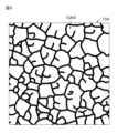
- FIG. 3 is a plan view showing an example of the surface shape of the recording layer in an unrecorded state.
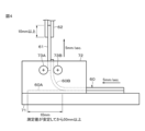
- FIG. 4 is a diagram of a test apparatus for a 90 degree peel test.
- FIG. 5 is a cross-sectional view showing the configuration of a recording medium according to a reference example.
- FIG. 6 is a diagram showing an example of an observed image when the recording layer of the recording medium according to the first embodiment is focused.
- 7A is a cross-sectional view showing a first example of the configuration of a recording medium according to Modification 1.
- FIG. 1 is a plan view showing an example of the appearance of a recording medium according to the first embodiment.
- FIG. 2 is a cross-sectional view showing an example of the configuration of the recording medium according to the first embodiment.
- FIG. 7B is a cross-sectional view showing a second example of the configuration of the recording medium according to Modification 1.
- FIG. 7C is a cross-sectional view showing a third example of the configuration of the recording medium according to Modification 1.
- FIG. 8A is a cross-sectional view showing a fourth example of the configuration of a recording medium according to modification 1.
- FIG. 8B is a cross-sectional view showing a fifth example of the configuration of the recording medium according to Modification 1.
- FIG. 8C is a cross-sectional view showing a sixth example of the configuration of the recording medium according to Modification 1.
- FIG. FIG. 9 is a cross-sectional view showing an example of the configuration of a recording medium according to Modification 2. As shown in FIG. FIG.
- FIG. 10A is a plan view showing an example of the appearance of a card according to the second embodiment
- FIG. 10B is a cross-sectional view along line XB-XB of FIG. 10A
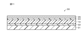
- 11 is a cross-sectional view showing an example of the configuration of a card according to Modification 1.
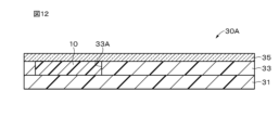
- FIG. FIG. 12 is a cross-sectional view showing an example of the configuration of a card according to the third embodiment.
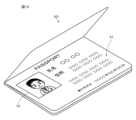
- FIG. 13 is a perspective view showing an example of the appearance of a booklet according to the fourth embodiment.
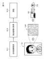
- FIG. 14 is a diagram showing an example of the configuration of an image authentication system according to the fifth embodiment.
- FIG. 15 is a diagram for explaining an example of the image registration operation of the image authentication system according to the fifth embodiment.
- FIG. 16 is a diagram for explaining an example of image authentication operation of the image authentication system according to the fifth embodiment.
- FIG. 1 is a plan view showing an example of the appearance of a recording medium 10 according to the first embodiment.
- the recording medium 10 is, for example, a recording medium for cards or passports, and a face photograph is drawn on the recording medium 10 .
- the recording medium 10 is configured to be able to change its coloring state by laser light irradiation (external stimulus).
- An image can be drawn on the recording medium 10 by this change in coloring state.
- the image is a photograph of the face will be described, but the image may be a photograph other than the photograph of the face.
- the image is not limited to a photograph, and may be a pattern, a color pattern, or the like, or may be text such as characters or symbols.
- the image may be composed of a combination of two or more of photographs, designs, colors and texts.
- the laser light is preferably near-infrared laser light.
- near-infrared laser light refers to laser light having a peak wavelength in a wavelength range of more than 780 nm and less than or equal to 2.5 ⁇ m.
- the change in coloring state may be a reversible change or an irreversible change. That is, the system of the recording medium 10 may be a rewritable system in which an image or the like can be rewritten, or a write-once system in which an image or the like can be written only once. From the viewpoint of falsification prevention, the change in the coloring state is preferably an irreversible change.
- FIG. 2 is a cross-sectional view showing an example of the configuration of the recording medium 10 according to the first embodiment.
- the recording medium 10 includes a substrate 11, an intermediate layer 12A, a recording layer 13A, an intermediate layer 12B, a recording layer 13B, an intermediate layer 12C, a recording layer 13C, an intermediate layer 12D, and a UV cut layer . , and the cover layer 15 in that order.
- the intermediate layer 12D, the UV cut layer 14 and the cover layer 15 are provided as required.
- the UV cut layer 14 may not be provided, or the intermediate layer 12D, the UV cut layer 14 and the cover layer 15 may not be provided.
- the intermediate layers 12A, 12B, 12C, and 12D may be collectively referred to as the intermediate layer 12 without any particular distinction.
- the recording layers 13A, 13B, and 13C may be collectively referred to as the recording layer 13 without any particular distinction.
- the recording layer 13A, the recording layer 13B, and the recording layer 13C are examples of a first recording layer, a second recording layer, and a third recording layer, respectively.
- the substrate 11 supports the intermediate layer 12A, the recording layer 13A, the intermediate layer 12B, the recording layer 13B, the intermediate layer 12C, the recording layer 13C, the intermediate layer 12D, the UV cut layer 14 and the cover layer 15.
- the base material 11 is preferably made of a material having excellent heat resistance and excellent dimensional stability in the planar direction.
- Substrate 11 may have the property of being either transparent or non-transmissive to visible light. In this specification, visible light refers to light in a wavelength range of 360 nm or more and 780 nm or less.
- the substrate 11 may have a predetermined color such as white.
- the substrate 11 has, for example, a plate shape or a film shape. In the present disclosure, film is defined to include sheet.
- the base material 11 may have rigidity or flexibility, for example. When the base material 11 has flexibility, a flexible recording medium 10 can be realized.
- the rigid base material 11 include a wafer and a glass substrate.
- the flexible substrate 11 include flexible glass, film, and paper.
- the base material 11 includes, for example, at least one selected from the group consisting of inorganic materials, metallic materials, polymeric materials, and the like.
- the inorganic material includes, for example, at least one selected from the group consisting of silicon (Si), silicon oxide ( SiOx ), silicon nitride ( SiNx ) and aluminum oxide ( AlOx ).
- Silicon oxide includes, for example, at least one selected from the group consisting of glass, spin-on-glass (SOG), and the like.
- the metal material includes, for example, at least one selected from the group consisting of aluminum (Al), nickel (Ni), stainless steel, and the like.
- the polymeric material is, for example, at least one selected from the group consisting of polycarbonate (PC), polyethylene terephthalate (PET), polyethylene naphthalate (PEN), polyethyletherketone (PEEK), polyvinyl chloride (PVC), and the like. include.
- PC polycarbonate
- PET polyethylene terephthalate
- PEN polyethylene naphthalate
- PEEK polyethyletherketone
- PVC polyvinyl chloride
- At least one of the first surface and the second surface of the substrate 11 may be provided with a reflective layer (not shown), and the substrate 11 itself functions as a reflective layer. may be combined. Since the base material 11 has such a structure, more vivid color display is possible.
- the recording layers 13A, 13B, and 13C in the recorded state are in the colored state, and the recording layers 13A, 13B, and 13C in the unrecorded state are in the decolored state.
- the recording layers 13A, 13B, and 13C can change from a decolored state to a colored state by irradiation with laser light.
- the decolorized state may be a state in which the laser light and visible light can be transmitted.
- the recording layers 13A, 13B, and 13C can exhibit different hues in the colored state. Specifically, the recording layer 13A can exhibit a magenta color in a colored state.
- the recording layer 13B can exhibit a cyan color in a colored state.
- the recording layer 13C can exhibit a yellow color in a colored state.
- Magenta, cyan, and yellow are examples of first, second, and third primary colors, respectively.
- the first primary color, the second primary color, and the third primary color may be three primary colors of color.
- the first primary color, second primary color, and third primary color may be colors other than magenta, cyan, and yellow.
- the laser light capable of changing the recording layer 13A to a colored state, the laser light capable of changing the recording layer 13B to a colored state, and the laser light capable of changing the recording layer 13C to a colored state are: Each has a different peak wavelength.
- FIG. 3 is a plan view showing an example of the surface of the recording layer 13A in an unrecorded state (uncolored state).
- the recording layer 13A has an uneven surface 13AS on the front surface side.
- the front surface of the recording layer 13A means the surface on which an image recorded on the recording layer 13A is observed.
- the front surfaces of the recording layer 13B and the recording layer 13C also mean the same contents as the front surface of the recording layer 13A. Since the recording layer 13A has the uneven surface 13AS, it is possible to increase the peel strength of the interface between the recording layer 13A and the intermediate layer 12B.
- the recording layer 13B has an uneven surface 13BS on the front surface side. Since the recording layer 13B has the uneven surface 13BS, it is possible to increase the peel strength at the interface between the recording layer 13B and the intermediate layer 12C.
- the recording layer 13C has an uneven surface 13CS on the front surface side. Since the recording layer 13C has the uneven surface 13CS, it is possible to increase the peel strength of the interface between the recording layer 13C and the intermediate layer 12C.
- the uneven surfaces 13AS, 13BS, and 13CS are composed of random unevenness.
- the random unevenness is formed by Benard cells, for example.
- the random unevenness formed by a Benard cell or the like is unique to each recording medium 10 and has a structure that is difficult to forge.
- the uneven surfaces 13AS, 13BS, and 13CS are collectively referred to without particular distinction, they may be referred to as the uneven surface 13S.
- the size of random unevenness in the uneven surface 13AS, the uneven surface 13BS, and the uneven surface 13CS is, for example, 50 ⁇ m or more and 100 ⁇ m or less.
- the height of the random unevenness in the uneven surface 13AS, the uneven surface 13BS, and the uneven surface 13CS is, for example, 2 ⁇ m or more and 3 ⁇ m or less.
- the size of random unevenness is obtained by one of the following methods (1) to (3).
- (1) Using a microscope equipped with a high-definition camera, the uneven shape of the surface of the recording layer is depth-stacked in the height direction to obtain image data. The length in the width direction of the acquired concavo-convex shape is measured to measure the size of the concavo-convex shape.
- (2) A cross section is taken with a microtome or the like, and the size of the unevenness of the recording layer 13 is measured with a SEM (Scanning Electron Microscope).
- (3) A mottled image is obtained by observing with a microscope the portion that has been uniformly colored after drawing. Since the size of the spots is caused by the unevenness of the recording layer 13, it can be considered to represent the size of the unevenness.
- the height of random unevenness is obtained by one of the following methods (4) and (5).
- (4) Using a microscope equipped with a high-definition camera, the uneven shape of the recording layer surface is depth-stacked in the height direction to obtain image data. The difference in height between peaks and valleys of the obtained uneven shape is measured to measure the height of the unevenness.
- (5) A cross section is taken with a microtome or the like, and the height of the unevenness of the recording layer 13 is measured with a SEM (Scanning Electron Microscope).
- the recording layer 13A in the recording state is formed with first pixels forming an image such as a photograph of the face.
- the first pixel is composed of a dot-shaped first coloring portion.
- the first pixel of the recording layer 13A, that is, the first coloring portion has a magenta color.
- second pixels forming an image such as a face photograph are formed.
- the second pixel is composed of a dot-shaped second coloring portion.
- the second pixel of the recording layer 13B, that is, the second coloring portion has a cyan color.
- third pixels forming an image such as a face photograph are formed.
- the third pixel is composed of a dot-shaped third coloring portion.
- the third pixel of the recording layer 13C, that is, the third coloring portion has a yellow color.
- each of the recording layers 13A, 13B, and 13C is preferably 1 ⁇ m or more and 20 ⁇ m or less, more preferably 2 ⁇ m or more and 15 ⁇ m or less, still more preferably 3 ⁇ m or more and 7 ⁇ m or less, for example about 5 ⁇ m.
- the thickness of the recording layers 13A, 13B, and 13C is 1 ⁇ m or more, the color density can be improved.
- the thickness of the recording layers 13A, 13B, and 13C is 20 ⁇ m or less, it is possible to suppress an increase in the amount of heat utilization of the recording layers 13A, 13B, and 13C, and to suppress deterioration of color developability.
- the recording layer 13A contains an electron-donating first color former, an electron-accepting first color developer, and a first photothermal conversion agent.
- the recording layer 13A preferably further contains a first matrix resin.
- the recording layer 13B contains an electron-donating second color former, an electron-accepting second color developer, and a second photothermal conversion agent.
- the recording layer 13B preferably further contains a second matrix resin.
- the recording layer 13C contains an electron-donating third color former, an electron-accepting third color developer, and a third photothermal conversion agent.
- the recording layer 13C preferably further contains a third matrix resin.
- the first, second, and third color formers can develop colors by reacting with the first, second, and third color developers, respectively.
- the first, second, and third color formers can exhibit different hues in the developed state. Specifically, the first color former can exhibit a magenta color in a colored state.
- the second color former can exhibit a cyan color in a colored state.
- the third color former can exhibit a yellow color in a colored state.
- the first, second, and third color-developing compounds are, for example, leuco dyes.
- leuco dyes When the lactone ring in the molecule of the leuco dye reacts with an acid, the lactone ring becomes a ring-opened state and develops color. When the lactone ring in the open state reacts with a base, the leuco dye may be closed and decolored.
- Leuco dyes can be, for example, existing thermal paper dyes.
- the first, second, and third color formers are not particularly limited and can be appropriately selected according to the purpose.
- the first, second, and third color-developing compounds are, for example, fluoran-based compounds, triphenylmethanephthalide-based compounds, azaphthalide-based compounds, phenothiazine-based compounds, leuco auramine-based compounds, and indolinophthalide-based compounds.
- the first, second and third color compounds are, for example, 2-anilino-3-methyl-6-diethylaminofluorane, 2-anilino-3-methyl-6-di(n-butyl amino)fluorane, 2-anilino-3-methyl-6-(Nn-propyl-N-methylamino)fluorane, 2-anilino-3-methyl-6-(N-isopropyl-N-methylamino)fluorane, 2-anilino-3-methyl-6-(N-isobutyl-N-methylamino)fluorane, 2-anilino-3-methyl-6-(Nn-amyl-N-methylamino)fluorane, 2-anilino- 3-methyl-6-(N-sec-butyl-N-methylamino)fluorane, 2-anilino-3-methyl-6-(Nn-amyl-N-ethylamino)fluoran
- the first, second, and third color developers are capable of developing colors for the first, second, and third color formers in a decolored state, respectively.
- the types of the first, second and third developers may be the same, or the types of the first, second and third developers may be different.
- the first, second, and third developers are compounds containing electron-accepting groups in their molecules.
- the electron-accepting moieties of the first, second, and third color developers react with the lactone rings of the first, second, and third color formers, respectively, and the lactone rings are opened to form the first , the second and third color formers develop colors.
- the first, second, and third color developers include, for example, at least one selected from the group consisting of phenol derivatives, salicylic acid derivatives, urea derivatives, and the like.
- the developer contains a compound represented by the following formula (1).
- X 0 is a divalent group containing at least one benzene ring.
- Y 01 and Y 02 are each independently monovalent groups.
- n01 and n02 are each independently an integer of 0 to 5. When n01 is an integer of 2 to 5, Y 01 may be the same or different, n02 is 2 When it is any integer from to 5, Y 02 may be the same or different, and Z 01 and Z 02 are each independently a hydrogen bonding group.
- X 0 contains at least one benzene ring
- the melting point can be made higher than when X 0 is an aliphatic hydrocarbon group (for example, normal alkyl chain).
- Characteristics (hereinafter referred to as "high temperature and high humidity storage characteristics") can be improved.
- X 0 preferably contains at least two benzene rings.
- High-temperature and high-humidity storage properties are, for example, storage properties in an environment of 80° C. and 60% RH.
- the heat resistance is improved, the resistance of the recording medium 10 to severe processes (for example, heat pressing, integral molding using molten resin, etc.) is improved.
- the at least two benzene rings may be fused. For example, it may be naphthalene or anthracene.
- a hydrogen-bonding group means a functional group containing atoms capable of hydrogen bonding with atoms present in other functional groups or other compounds.
- the developer preferably contains a compound represented by the following formula (2).
- X 1 is a divalent group containing at least one benzene ring.
- Y 11 , Y 12 , Y 13 , and Y 14 are each independently a monovalent group.
- Z 11 and Z 12 are each independently a hydrogen-bonding group.
- X 1 contains at least one benzene ring
- the melting point can be made higher than when X 1 is an aliphatic hydrocarbon group (for example, a normal alkyl chain), thereby improving high-temperature and high-humidity storage properties. be able to.
- X 1 preferably contains at least two benzene rings.
- at least two benzene rings may be fused. For example, it may be naphthalene or anthracene.
- the hydrocarbon group is a general term for groups composed of carbon (C) and hydrogen (H), even if it is a saturated hydrocarbon group. Alternatively, it may be an unsaturated hydrocarbon group.
- a saturated hydrocarbon group is an aliphatic hydrocarbon group having no carbon-carbon multiple bonds
- an unsaturated hydrocarbon group is an aliphatic hydrocarbon group having a carbon-carbon multiple bond (a carbon-carbon double bond or a carbon-carbon triple bond). is the base.
- the hydrocarbon group may be chain-shaped or may contain one or more rings.
- the chain may be linear or branched having one or more side chains or the like.
- X 0 in formula (1) and X 1 in formula (2) are, for example, divalent groups containing one benzene ring.
- the divalent group is represented, for example, by the following formula (3).
- X 21 may or may not be present, and when X 21 is present, X 21 is a divalent group.
- X 22 may or may not be present, and X 22 is In some cases, X 22 is a divalent group R 21 is a monovalent group n21 is an integer from 0 to 4 n21 is an integer from 2 to 4 , R 21 may be the same or different from each other.* indicates a bond.
- the bonding positions of X 21 and X 22 to the benzene ring are not limited. That is, the bonding position of X 21 and X 22 to the benzene ring may be any of the ortho-, meta- and para-positions.
- the divalent group containing one benzene ring is preferably represented by the following formula (4) from the viewpoint of improving high-temperature and high-humidity storage properties.
- R 22 is a monovalent group.
- n22 is an integer of 0 to 4.
- R 22 may be the same as or different from each other.* indicates a joint.
- the bonding positions of Z 01 and Z 02 with respect to the benzene ring are not limited in formula (4). That is, the bonding positions of Z 01 and Z 02 with respect to the benzene ring may be any of ortho, meta and para positions.
- the bonding positions of Z 11 and Z 12 with respect to the benzene ring are not limited in formula (4). That is, the bonding positions of Z 11 and Z 12 with respect to the benzene ring may be any of ortho, meta and para positions.
- X21 , X22 ) X 21 and X 22 in formula (3) are each independently a divalent group and are not particularly limited. It is a hydrogen group.
- the hydrocarbon group is preferably chain-like. If the hydrocarbon group is chain-like, the melting point of the color developer can be lowered, so that the color developer melts upon irradiation with a laser beam, making it easier for the color former to develop color. From the viewpoint of reducing the melting point of the color developer, a normal alkyl chain is particularly preferred among chain hydrocarbon groups.
- the number of carbon atoms in the optionally substituted hydrocarbon group is, for example, 1 to 15, 1 to 13, 1 to 12, 1 to 10, 1 to 6, or 1 to 3. .
- the number of carbon atoms in the normal alkyl group is preferably 8 or less, more preferably 6 or less, and even more preferably 6 or less, from the viewpoint of high-temperature storage stability. is 5 or less, particularly preferably 3 or less.
- the number of carbon atoms in the normal alkyl group is 8 or less, the length of the normal alkyl group is short, so that the color developer is less likely to be thermally disturbed during high-temperature storage, and interacts with a color former such as a leuco dye during color development. It is thought that it becomes difficult to remove the part that was attached. Therefore, the color-developing compound such as the leuco dye is less likely to decolor during high-temperature storage, thereby improving the high-temperature storage stability.
- the hydrocarbon group may have include a halogen group (eg, fluorine group) or an alkyl group having a halogen group (eg, fluorine group).
- the hydrocarbon group which may have a substituent may be one in which part of the carbon atoms of the hydrocarbon group (for example, part of the carbon atoms contained in the main chain of the hydrocarbon group) is substituted with an element such as oxygen. .
- R21 ) R 21 in formula (3) is not particularly limited as long as it is a monovalent group, but for example, it is a halogen group or a hydrocarbon group which may have a substituent. .
- a halogen group is, for example, a fluorine group (-F), a chlorine group (-Cl), a bromine group (-Br) or an iodine group (-I).
- the number of carbon atoms in the optionally substituted hydrocarbon group is, for example, 1 to 15, 1 to 13, 1 to 12, 1 to 10, 1 to 6, or 1 to 3. .
- the hydrocarbon group may have include a halogen group (eg, fluorine group) or an alkyl group having a halogen group (eg, fluorine group).
- the hydrocarbon group which may have a substituent may be one in which part of the carbon atoms of the hydrocarbon group (for example, part of the carbon atoms contained in the main chain of the hydrocarbon group) is substituted with an element such as oxygen. .
- R22 ) R 22 in formula (4) is not particularly limited as long as it is a monovalent group, but for example, it is a halogen group or a hydrocarbon group which may have a substituent. .
- a halogen group and a hydrocarbon group which may have a substituent are the same as those defined for R 21 in the above formula (3).
- X 0 in formula (1) and X 1 in formula (2) are, for example, divalent groups containing two benzene rings.
- the divalent group is represented, for example, by the following formula (5).
- X 31 may or may not be present, and when X 31 is present, X 31 is a divalent group.
- X 32 may or may not be present, and X 32 is In some cases, X 32 is a divalent group.
- X 33 may or may not be present, and when X 33 is present, X 33 is a divalent group.
- R 31 and R 32 are each independently , a monovalent group
- n31 and n32 are each independently an integer of 0 to 4. When n31 is an integer of 2 to 4, R 31 are the same When n32 is an integer of 2 to 4, R 32 may be the same or different, and * indicates a bond.
- the binding positions of X 31 and X 32 to the benzene ring are not limited. That is, the bonding positions of X 31 and X 32 to the benzene ring may be any of ortho, meta and para positions.
- the bonding positions of X 32 and X 33 to the benzene ring are not limited. That is, the bonding positions of X 32 and X 33 to the benzene ring may be any of ortho, meta and para positions.
- the divalent group containing two benzene rings is preferably represented by the following formula (6) from the viewpoint of improving high-temperature and high-humidity storage properties.
- X 34 is a divalent group.
- R 33 and R 34 are each independently a monovalent group.
- n33 and n34 are each independently 0 to 4 When n33 is an integer of 2 to 4, R 33 may be the same or different, and n34 is an integer of 2 to 4 , R 34 may be the same or different from each other.* indicates a bond.
- the bonding positions of Z 01 and X 34 to the benzene ring are not limited. That is, the bonding positions of Z 01 and X 34 with respect to the benzene ring may be any of ortho, meta and para positions.
- the binding positions of Z 02 and X 34 to the benzene ring are not limited. That is, the bonding positions of Z 02 and X 34 with respect to the benzene ring may be any of ortho, meta and para positions.
- the bonding positions of Z 11 and X 34 to the benzene ring are not limited. That is, the bonding positions of Z 11 and X 34 with respect to the benzene ring may be any of ortho, meta and para positions.
- the bonding positions of Z 12 and X 34 to the benzene ring are not limited. That is, the bonding positions of Z 12 and X 34 with respect to the benzene ring may be any of ortho, meta and para positions.
- X 31 , X 32 , and X 33 in formula (5) are each independently a divalent group, and are not particularly limited. is a good hydrocarbon group.
- the hydrocarbon group is the same as X 21 and X 22 in formula (3) above.
- X 34 in formula (6) is not particularly limited as long as it is a divalent group, but for example, it is a hydrocarbon group which may have a substituent.
- the hydrocarbon group is the same as X 21 and X 22 in formula (3) above.
- R31 , R32 ) R 31 and R 32 in formula (5) are not particularly limited as long as they are monovalent groups, but for example, a halogen group or an optionally substituted hydrocarbon is the base.
- the halogen group and the optionally substituted hydrocarbon group are the same as R 21 in the above formula (3).
- R33 , R34 R 33 and R 34 in formula (6) are not particularly limited as long as they are monovalent groups, but for example, a halogen group or an optionally substituted hydrocarbon is the base.
- the halogen group and the optionally substituted hydrocarbon group are the same as R 21 in the above formula (3).
- Y01 , Y02 ) Y 01 and Y 02 in formula (1) are each independently, for example, a hydrogen group (-H), a hydroxy group (-OH), a halogen group (-X), a carboxy group (-COOH), an ester group ( —COOR) or a hydrocarbon group optionally having a substituent.
- a halogen group is, for example, a fluorine group (-F), a chlorine group (-Cl), a bromine group (-Br) or an iodine group (-I).
- the number of carbon atoms in the optionally substituted hydrocarbon group is, for example, 1 to 15, 1 to 13, 1 to 12, 1 to 10, 1 to 6, or 1 to 3. .
- the hydrocarbon group may have include a halogen group (eg, fluorine group) or an alkyl group having a halogen group (eg, fluorine group).
- the hydrocarbon group which may have a substituent may be one in which part of the carbon atoms of the hydrocarbon group (for example, part of the carbon atoms contained in the main chain of the hydrocarbon group) is substituted with an element such as oxygen. .
- one of (Y 01 ) n01 and/or one of (Y 02 ) n02 is preferably a hydroxy group (--OH).
- display quality and light fastness can be improved.
- the bonding positions of Y 11 and Y 12 to the benzene ring are not limited. That is, the bonding position of Y 11 and Y 12 to the benzene ring may be any of the ortho-, meta- and para-positions.
- the binding positions of Y 13 and Y 14 to the benzene ring are not limited. That is, the bonding positions of Y 13 and Y 14 to the benzene ring may be any of ortho, meta and para positions.
- the bonding positions of Y 11 and Y 12 to one benzene and the bonding positions of Y 13 and Y 14 to the other benzene may be the same or different.
- Y 11 , Y 12 , Y 13 and Y 14 in formula (2) are each independently, for example, a hydrogen group (--H), a hydroxy group (--OH), a halogen group, a carboxy group (--COOH), an ester It is a group (--COOR) or a hydrocarbon group optionally having a substituent.
- the halogen group and the optionally substituted hydrocarbon group are the same as Y 01 and Y 02 in formula (1) above.
- Y 11 and/or Y 13 are preferably hydroxy groups (--OH).
- Y 11 and/or Y 13 are hydroxy groups (--OH)
- display quality and light resistance can be improved.
- Z 01 and Z 02 in formula (1) are each independently, for example, a urea bond (--NHCONH--), an amide bond (--NHCO--, --OCHN--) or a hydrazide bond (--NHCOCONH--).
- Z 01 and Z 02 are preferably urea bonds from the viewpoint of improving high-temperature and high-humidity storage properties.
- Z 01 is an amide bond
- the nitrogen contained in the amide bond may be bonded to benzene, or the carbon contained in the amide bond may be bonded to benzene.
- Z 02 is an amide bond
- the nitrogen contained in the amide bond may be bonded to benzene, or the carbon contained in the amide bond may be bonded to benzene.
- Z 11 and Z 12 in formula (2) are each independently, for example, a urea bond (--NHCONH--), an amide bond (--NHCO--, --OCHN--) or a hydrazide bond (--NHCOCONH--).
- Z 11 and Z 12 are preferably urea bonds from the viewpoint of improving high-temperature and high-humidity storage properties.
- Z 11 is an amide bond
- the nitrogen contained in the amide bond may be bonded to benzene, or the carbon contained in the amide bond may be bonded to benzene.
- Z 12 is an amide bond
- the nitrogen contained in the amide bond may be bonded to benzene, or the carbon contained in the amide bond may be bonded to benzene.
- color developers in which X 0 in formula (1) and X 1 in formula (2) contain two benzene rings are represented by the following formulas (8-1) to (8-8) It contains at least one selected from the group consisting of the compounds represented.
- the first, second, and third photothermal conversion agents can absorb light in a predetermined wavelength range such as the near-infrared region to generate heat.
- the first, second and third photothermal conversion agents have different absorption wavelength peaks. Specifically, the first photothermal conversion agent has an absorption wavelength peak at wavelength ⁇ 1 .
- the second photothermal conversion agent has an absorption wavelength peak at wavelength ⁇ 2 .
- the third photothermal conversion agent has an absorption wavelength peak at wavelength ⁇ 3 .
- the wavelengths ⁇ 1 , ⁇ 2 and ⁇ 3 are different from each other.
- the absorption wavelength peak is preferably in the near-infrared region.
- the near-infrared region is, for example, a wavelength range of 700 nm or more and 2000 nm or less.
- the first, second, and third photothermal conversion agents have absorption wavelength peaks different from each other, so that a desired layer among the recording layers 13A, 13B, and 13C is selectively colored by irradiation with a laser beam.
- the first, second, and third photothermal conversion agents it is preferable to use near-infrared absorbing dyes that have little absorption in the visible region.
- the first, second, and third photothermal conversion agents are, for example, at least one selected from the group consisting of compounds having a phthalocyanine skeleton (phthalocyanine dyes), compounds having a squarylium skeleton (squarylium dyes), inorganic compounds, and the like. Contains seeds.
- inorganic compounds include metal complexes such as dithio complexes, diimmonium salts, aminium salts, graphite, carbon black, metal powder particles, tricobalt tetraoxide, iron oxide, chromium oxide, copper oxide, titanium black, ITO (Indium Tin Oxide ), metal nitrides such as niobium nitride, metal carbides such as tantalum carbide, metal sulfides, and various magnetic powders.
- the inorganic compound may contain a compound having a cyanine skeleton (cyanine dye) with excellent light resistance and heat resistance.
- excellent light resistance means that the material does not decompose under the environment of use, for example, by irradiation with light from a fluorescent lamp or the like.
- Excellent heat resistance means that, for example, when a film is formed together with a polymer material and stored at 150° C. for 30 minutes, the maximum absorption peak value of the absorption spectrum does not change by 20% or more.
- Compounds having such a cyanine skeleton include, for example, counter ions of SbF 6 , PF 6 , BF 4 , ClO 4 , CF 3 SO 3 and (CF 3 SO 3 ) 2 N in the molecule. and a methine chain containing a 5- or 6-membered ring.
- the compound having a cyanine skeleton used in the recording medium 10 in the first embodiment has both of the above counter ions and a cyclic structure such as a 5-membered ring and a 6-membered ring in the methine chain. is preferable, but if at least one of them is provided, sufficient light resistance and heat resistance are ensured.
- the first, second and third matrix resins function as binders.
- the first matrix resin is preferably one in which the first color former, the first color developer and the first photothermal conversion agent are easily dispersed homogeneously.
- the second matrix resin is preferably one in which the second color former, the second color developer and the second photothermal conversion agent are easily dispersed homogeneously.
- the third matrix resin is preferably one in which the third color former, the third color developer and the third photothermal conversion agent are easily dispersed homogeneously.
- the types of the first, second and third matrix resins may be the same, or the types of the first, second and third matrix resins may be different.
- the first, second, and third matrix resins include, for example, at least one selected from the group consisting of thermosetting resins and thermoplastic resins.
- the first, second and third matrix resins preferably contain a polycarbonate resin. Since the first, second, and third matrix resins contain a polycarbonate-based resin, the light resistance of the background of the recording medium 10 can be improved.
- the first, second, and third matrix resins may be polyvinyl chloride, polyvinyl acetate, vinyl chloride-vinyl acetate copolymer, ethyl cellulose, polystyrene, styrenic copolymers, instead of polycarbonate resins or together with polycarbonate resins.
- the recording layers 13A, 13B, and 13C may further contain at least one additive selected from the group consisting of sensitizers, ultraviolet absorbers, and the like, if necessary.
- the recording layers 13A, 13B, and 13C preferably contain an amine-based compound from the viewpoint of suppressing coloring of the background.
- the recording layers 13A, 13B, and 13C contain an amine compound
- the recording layers 13A, 13B, and 13C contain at least one compound selected from the group consisting of an epoxy compound and a carbodiimide compound together with the amine compound. is preferred. If the recording layers 13A, 13B, and 13C contain an amine compound, the reliability of the coloring portion may be lowered during high-temperature, high-humidity storage. When at least one compound selected from the group consisting of carbodiimide-based compounds is included, it is possible to suppress deterioration in the reliability of the color-developing portion during high-temperature, high-humidity storage due to amine-based compounds.
- the intermediate layer 12A is provided between the substrate 11 and the recording layer 13A.
- the intermediate layer 12A can insulate between the substrate 11 and the recording layer 13A, and can suppress the diffusion of constituent materials between the substrate 11 and the recording layer 13A.
- the intermediate layer 12B is provided between the recording layer 13A and the recording layer 13B.
- the intermediate layer 12B can insulate between the recording layer 13A and the recording layer 13B, and can suppress diffusion of constituent materials between the recording layer 13A and the recording layer 13B.
- the intermediate layer 12C is provided between the recording layer 13B and the recording layer 13C.
- the intermediate layer 12C can insulate between the recording layer 13B and the recording layer 13C, and can suppress diffusion of constituent materials between the recording layer 13B and the recording layer 13C.
- the intermediate layer 12D is provided between the recording layer 13C and the UV cut layer .
- the intermediate layer 12D can insulate the space between the recording layer 13C and the UV cut layer 14, and can suppress diffusion of constituent materials between the recording layer 13C and the UV cut layer 14.
- the intermediate layer 12A may be transmissive or impermeable to the laser light and visible light used for drawing on the recording medium 10.
- the intermediate layers 12B, 12C, and 12D are transparent to laser light and visible light used for drawing on the recording medium 10.
- the thicknesses of the intermediate layers 12A, 12B, 12C, and 12D are each independently preferably 3 ⁇ m or more and 100 ⁇ m or less, more preferably 5 ⁇ m or more and 50 ⁇ m or less, still more preferably 7 ⁇ m or more and 15 ⁇ m or less, for example about 10 ⁇ m.
- the thickness of the intermediate layers 12A, 12B, 12C, and 12D is 3 ⁇ m or more, a sufficient heat insulating effect and a sufficient diffusion suppressing effect can be obtained.
- the thickness of the intermediate layers 12A, 12B, 12C, and 12D is 50 ⁇ m or less, a decrease in translucency can be suppressed.
- the thicknesses of the intermediate layers 12A, 12B, 12C and 12D may be the same or different.
- the intermediate layer 12A includes an adhesive layer 12A- 1 and an ultraviolet curable resin layer 12A- 2 on the substrate 11 in this order.
- the adhesive layer 12A- 1 adheres the base material 11 and the ultraviolet curing resin layer 12A- 2 together.
- the adhesive layer 12A1 may be able to insulate between the substrate 11 and the recording layer 13A.
- the ultraviolet curable resin layer 12A2 can insulate between the base material 11 and the recording layer 13A, and is a constituent material (for example, a first color former compound, etc.) between the base material 11 and the recording layer 13A. diffusion can be suppressed.
- the intermediate layer 12A may further comprise a film (not shown). The film is provided, for example, between the adhesive layer 12A- 1 and the ultraviolet curable resin layer 12A- 2 .
- As the material of the film the same material as the polymeric material of the substrate 11 can be exemplified.
- the intermediate layer 12B includes an adhesive layer 12B1 and an ultraviolet curable resin layer 12B2 in this order on the recording layer 13A.
- the adhesive layer 12B- 1 adheres the recording layer 13A and the ultraviolet curing resin layer 12B- 2 together.
- the adhesive layer 12B1 is adjacent to the uneven surface 13AS.
- the adhesive layer 12B1 may be able to insulate between the recording layer 13A and the recording layer 13B.
- the ultraviolet curable resin layer 12B2 can insulate the space between the recording layer 13A and the recording layer 13B, and the constituent material (for example, the first and second color properties) between the recording layer 13A and the recording layer 13B. compounds, etc.) can be suppressed.
- the intermediate layer 12B may further comprise a film (not shown).
- the film is provided, for example, between the adhesive layer 12B- 1 and the ultraviolet curable resin layer 12B- 2 .
- As the material of the film the same material as the polymeric material of the substrate 11 can be exemplified.
- the intermediate layer 12C includes an adhesive layer 12C1 and an ultraviolet curable resin layer 12C2 in this order on the recording layer 13B.
- the adhesive layer 12C1 adheres the recording layer 13B and the ultraviolet curing resin layer 12C2 together.
- the adhesive layer 12C1 is adjacent to the uneven surface 13BS.
- the adhesive layer 12C1 may be able to insulate between the recording layer 13B and the recording layer 13C.
- the ultraviolet curable resin layer 12C2 can insulate the space between the recording layer 13B and the recording layer 13C, and the constituent material (for example, the second and third color properties) between the recording layer 13B and the recording layer 13C. compounds, etc.) can be suppressed.
- the intermediate layer 12C may further comprise a film (not shown).
- the film is provided, for example, between the adhesive layer 12C1 and the ultraviolet curing resin layer 12C2 .
- As the material of the film the same material as the polymeric material of the substrate 11 can be exemplified.
- the intermediate layer 12D includes an adhesive layer 12D1 and an ultraviolet curable resin layer 12D2 in this order on the recording layer 13C.
- the adhesive layer 12D- 1 adheres the recording layer 13C and the ultraviolet curing resin layer 12D- 2 together.
- the adhesive layer 12D1 is adjacent to the uneven surface 13CS.
- the adhesive layer 12D1 may be able to insulate between the recording layer 13C and the UV cut layer .
- the ultraviolet curable resin layer 12D2 can insulate between the recording layer 13C and the UV cut layer 14, and the constituent material (for example, the third color former compound) between the recording layer 13C and the UV cut layer 14 etc.) can be suppressed.
- the adhesive layers 12A 1 , 12B 1 , 12C 1 and 12D 1 are, for example, double-sided adhesive films such as OCA (Optical Clear Adhesive).
- the ultraviolet curable resin layers 12A 2 , 12B 2 , 12C 2 , and 12D 2 contain ultraviolet curable resins that are polymerized and solidified. More specifically, for example, the ultraviolet curable resin layers 12A 2 , 12B 2 , 12C 2 , and 12D 2 are composed of a polymer of a polymerizable compound and a polymerization initiator to generate active species by irradiation of external energy (ultraviolet rays). Including those with structural changes.
- the UV curable resin composition includes, for example, at least one selected from the group consisting of radical polymerizable UV curable resin compositions and cationic polymerizable UV curable resin compositions.
- the UV curable resin composition may contain at least one selected from the group consisting of sensitizers, fillers, stabilizers, leveling agents, antifoaming agents, viscosity modifiers and the like, if necessary.
- the average peel strength at the interface between the recording layer 13A and the intermediate layer 12B, the average peel strength at the interface between the recording layer 13B and the intermediate layer 12C, and the average peel strength at the interface between the recording layer 13C and the intermediate layer 12D are respectively , preferably 3.5 N/cm or more, more preferably 4.0 N/cm or more, still more preferably 5.0 N/cm or more.
- the average peel strength at each interface is 3.5 N/cm or more, peeling at each interface can be suppressed. Therefore, falsification of the recording medium 10 can be prevented.
- the average peel strength of the interface between the recording layer 13A and the intermediate layer 12B is obtained by conducting a 90 degree peel test.
- the 90-degree peel test will be described below with reference to FIG.
- the recording medium 10 is cut into a strip having a width of 10 mm and a length of 100 mm to prepare a test piece 60, which is left for 24 hours or longer in a standard atmosphere of 23 ⁇ 1° C. and 50 ⁇ 5% relative humidity.
- the laminate below the interface between the recording layer 13A and the intermediate layer 12B is referred to as an adherend 60A
- the laminate above the interface is referred to as an adherend 60B.
- a notch was made between the adherend 60A and the adherend 60B with a sharp blade such as a cutter, and the adherend 60B was elongated in the longitudinal direction.
- the surface of the test piece 60 on the side of the adherend 60A is fixed to the test table 71 with a strong adhesive.
- the adhesive has sufficiently high adhesive strength so that the test piece 60 does not separate from the test table 71 when measuring the peel strength between the recording layer 13A and the intermediate layer 12B.
- Adhesive tape Scotch® is chosen.
- one end of the tension member 61 is attached to the intermediate layer 12B side surface of the adherend 60B.
- the tensile member 61 a band-shaped film having sufficient strength that does not cause elongation or breakage during peel strength measurement is used.
- one end of the tension member 61 is attached to the adherend 60B with a sufficiently high adhesive force so that the tension member 61 does not separate from the adherend 60A when the peel strength is measured.
- FIG. 4 shows an example in which the tension member 61 is gripped and used as a margin. The adherend 60B may be clamped as it is.
- the clamping device (metal plate ) 62 clamps and fixes the gripping margin by 10 mm or more.
- the movable rolls 73A and 73B serve as fulcrums for peeling during the 90 degree peeling test.
- a 90-degree peel test is performed using a tensile compression tester, and the test force [N / cm] and stroke [mm] are monitored as voltage values, for example, by a data logger manufactured by Keyence Corporation, and converted to force. and stored in the memory as CSV output data.
- the 90-degree peel test was performed at a speed of 5 mm/sec. is performed at a tensile speed of A stroke is set to 50 mm or more.
- the above 90-degree peel test is performed three times in total, and the point where the peel strength is stable (where the force rises slowly) is set as the starting point (0 mm), and the CSV output data from there to a position relatively distant by 50 mm. Calculate the average value by arithmetic mean. Thereby, the average peel strength between the recording layer 13A and the intermediate layer 12B is obtained. However, if the CSV output data contains a point (spike) at which the peel strength suddenly drops, the average peel strength is calculated by excluding this point (spike) from the CSV output data.
- the peel strength at the interface between the recording layer 13B and the intermediate layer 12C and the peel strength at the interface between the recording layer 13C and the intermediate layer 12D are measured in the same procedure as the peel strength at the interface between the recording layer 13A and the intermediate layer 12B. is required.
- FIG. 6 shows an example of an image 10P (hereinafter referred to as "internal image 10P") captured at a high magnification by focusing the optical microscope on the recording layer 13B of the recording medium 10, as indicated by the light beam L in FIG. It is a figure shown typically.
- shaded areas indicate colored areas.
- the colored portions are observed as spots.
- the spot-like colored portions as in the internal image 10P of the recording medium 10 are not observed.
- the recording medium 10 according to the first embodiment can obtain a spotted image (internal image 10P) caused by the uneven surface 13S by imaging the recording medium 10 with the focus on the recording layer 13. is configured to In the internal image 10P of the recording medium 10 according to the first embodiment, colored portions are observed as spots. The spots are unique patterns for each recording medium 10 . Therefore, the spots can be used to determine the authenticity of the recording medium 10 or to determine the authenticity of a card or booklet including the recording medium 10 .
- the recording medium 10 is divided between the adhesive layer 12A1 and the UV curable resin layer 12A2 , between the adhesive layer 12B1 and the UV curable resin layer 12B2 , and between the adhesive layer 12C1 and the UV curable resin layer 12C2 .
- a case where a film is provided between them will be described as an example.
- illustration of the said film is abbreviate
- Step of forming first laminated film First, a first matrix resin is dissolved in a solvent (eg, methyl ethyl ketone). Next, the first color former compound in a decolored state, the first color developer, and the first photothermal conversion agent are added to this solution and dispersed. Thus, the coating material for forming the first recording layer is prepared. Subsequently, after coating an ultraviolet curable resin on a film such as a PET film, the ultraviolet curable resin is irradiated with ultraviolet rays to be cured, thereby forming the ultraviolet curable resin layer 12A2 .
- a solvent eg, methyl ethyl ketone
- a recording layer 13A having an uneven surface 13AS is formed by applying a first recording layer forming coating material onto the ultraviolet curable resin layer 12A2 and drying it.
- a first laminated film composed of the film, the ultraviolet curable resin layer 12A2 , and the recording layer 13A having the uneven surface 13AS on its surface is obtained.
- the uneven surface 13AS of the recording layer 13A is formed, for example, by adjusting the coating conditions and drying conditions of the first recording layer forming coating material to form Benard cells in the coating film.
- An example of coating conditions and drying conditions for the first recording layer forming coating material is shown below.
- Coating method gravure coating method
- Coating thickness 30 ⁇ m or more and 40 ⁇ m or less (coating thickness when the thickness of the recording layer 13A after drying is 5 ⁇ m or more and 6 ⁇ m or less)
- Drying temperature 80°C or higher and 110°C or lower
- the uneven surface 13AS of the recording layer 13A is determined by the blending of additives for the first recording layer forming coating material, the selection of the type of color developer, the selection of the type of dispersion medium, the selection of the type of matrix resin, and the particle size of the color developer. It is also possible to form Benard cells by adjusting the distribution or adjusting the viscosity of the dispersion.
- the method of forming the uneven surface 13AS (adjustment of coating conditions and drying conditions, blending of additives, selection of the type of color developer, selection of the type of dispersion medium, selection of the type of matrix resin, particle size distribution of the color developer and adjustment of the viscosity of the dispersion) can be combined.
- Step of forming second laminated film A second matrix resin, a second color former, and a second developer instead of the first matrix resin, the first color former, the first color developer, and the first photothermal conversion agent
- a second layer comprising a film, an ultraviolet curable resin layer 12B2 , and a recording layer 13B having an uneven surface 13BS is formed in the same manner as in the first laminated film formation process, except that the agent and the second photothermal conversion agent are used. 2 laminated film is obtained.
- Step of forming third laminated film A third matrix resin, a third color former, and a third developer instead of the first matrix resin, the first color former, the first color developer, and the first photothermal conversion agent
- a second layer comprising a film, an ultraviolet curable resin layer 12C2 , and a recording layer 13C having an uneven surface 13CS is formed in the same manner as in the step of forming the first laminated film, except that the agent and the third photothermal conversion agent are used.
- a laminated film of No. 3 is obtained.
- a fourth laminated film is prepared in which the cover layer 15, the UV cut layer 14, and the UV curable resin layer 12D2 are provided in this order.
- a third laminate is formed on the adhesive layer 12D 1 so that the adhesive layer 12D 1 and the recording layer 13C are in contact with each other. Stick the film together.
- a second laminated film is attached on the adhesive layer 12C- 1 so that the adhesive layer 12C- 1 and the recording layer 13B are in contact with each other.
- the first laminated film is attached on the adhesive layer 12B- 1 so that the adhesive layer 12B- 1 and the recording layer 13A are in contact with each other.
- the base material 11 is pasted on the adhesive layer 12A- 1 .
- the recording medium 10 shown in FIG. 2 is obtained.
- the recording layer 13A is colored magenta as follows.
- the first photothermal conversion agent contained in the irradiated portion of the laser beam absorbs the near-infrared laser beam and generates heat.
- This heat causes the first color developer to melt, causing a color reaction (color development reaction) between the first color developer and the first color former, and the laser beam irradiated portion to develop a magenta color. .
- the recording layer 13B is colored cyan in the following manner.
- a predetermined position of the recording layer 13B is irradiated with a near-infrared laser beam having a peak wavelength of ⁇ 2
- the portion irradiated with the laser beam develops a cyan color due to the reaction similar to that of the recording layer 13A.
- the recording layer 13C is colored yellow in the following manner.
- a predetermined position of the recording layer 13B is irradiated with a near-infrared laser beam having a peak wavelength of ⁇ 3
- the portion irradiated with the laser beam develops a yellow color due to the reaction similar to that of the recording layer 13A.
- a desired full-color image is drawn on the recording medium 10 by coloring magenta, cyan, and yellow at predetermined positions of the recording layers 13A, 13B, and 13C, respectively.
- the recording layers 13A, 13B and 13C respectively have the uneven surfaces 13AS, 13BS and 13CS on the front surface side.
- the uneven surfaces 13AS, 13BS, and 13CS are composed of random unevenness.
- the random unevenness is unique to each recording medium 10 and has a structure that is difficult to forge. Therefore, it is possible to determine the authenticity of the recording medium 10 by using the uneven surfaces 13AS, 13BS, 13CS or patterns (spotted images) resulting from their shapes.
- the recording layers 13A, 13B, and 13C respectively have the uneven surfaces 13AS, 13BS, and 13CS on the front surface side, the interface between the recording layer 13A and the intermediate layer 12B, the recording layer 13B, and the intermediate layer 12C and the interface between the recording layer 13C and the intermediate layer 12D. Therefore, it is possible to improve falsification prevention.
- the recording layers 13A, 13B, and 13C are capable of presenting magenta, cyan, and yellow, respectively, in a colored state. Therefore, a desired image can be drawn in full color.
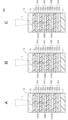
- the recording layer 13C closest to the cover layer 15 has an uneven surface 13CS on the front surface side.
- the recording layers 13A and 13B may respectively have planes 113AS and 113BS on the front side.
- the recording layer 13B which is the second closest to the cover layer 15 among the recording layers 13A, 13B, and 13C, has an uneven surface 13BS on the front surface side, whereas the recording layer 13B has an uneven surface 13BS on the front surface side.
- the recording layers 13A and 13C other than the recording layers 13A and 13C may respectively have flat surfaces 113AS and 113CS on the front side.
- the recording layer 13A farthest from the cover layer 15 has an uneven surface 13AS on the front surface side.
- the recording layers 13B and 13C may respectively have planes 113BS and 113CS on the front side.
- the recording layer 13C closest to the cover layer 15 and the recording layer 13B second closest to the cover layer 15 each have unevenness on the front surface side.
- the recording layer 13A farthest from the cover layer 15 may have the flat surface 113AS on the front surface side.
- the recording layer 13C closest to the cover layer 15 and the recording layer 13A furthest from the cover layer 15 each have an uneven surface 13CS on the front surface side.
- the uneven surface 13AS, the recording layer 13B that is second closest to the cover layer 15 may have a flat surface 113BS on the front surface side.
- the recording layer 13B that is the second closest to the cover layer 15 and the recording layer 13A that is the farthest from the cover layer 15 each have unevenness on the front side.
- the recording layer 13C closest to the cover layer 15 may have the flat surface 113CS on the front surface side.
- the recording medium 10 may have one recording layer 13 .
- FIG. 9 is a cross-sectional view showing an example of the configuration of the recording medium 10 having one recording layer 13D.
- the recording medium 10 may include a substrate 11, an intermediate layer 12A, a recording layer 13D, an intermediate layer 12D, a UV cut layer 14, and a cover layer 15 in this order.
- the recording layer 13D has an uneven surface 13DS on the front surface side.
- the uneven surface 13DS is the same as the uneven surface 13AS of the recording layer 13A in the first embodiment.
- the recording layer 13D can exhibit a predetermined color in a colored state. Predetermined colors include, for example, black, cyan, magenta, yellow, red, green, or blue, but are not limited to these colors.
- the recording layer 13D is the same as the recording layer 13A in the first embodiment except that it can exhibit a predetermined color in the colored state. That is, the recording layer 13D is the same as the recording layer 13A in the first embodiment except that it contains a coloring compound capable of exhibiting a predetermined color in a colored state.
- the recording medium 10 includes three recording layers 13
- the above recording layer 13 may be provided.
- the intermediate layer 12 may be provided between the laminated recording layers 13 .
- Each of the plurality of recording layers 13 may be capable of presenting different hues in the colored state.
- the color former contained in each of the plurality of recording layers 13 may be capable of presenting different hues in the colored state.
- the photothermal conversion agents contained in each of the plurality of recording layers 13 may have different absorption wavelength peaks.
- At least one of the plurality of recording layers 13 may have an uneven surface on the front surface side.
- all of the plurality of recording layers 13 may have an uneven surface on the front surface side, or a specific layer among the plurality of recording layers 13 may have an uneven surface on the front surface side.
- layers other than the specific layer may not have an uneven surface on the front surface side.
- Layers other than the specific layer may have a flat surface on the front surface side, for example.
- the number of specific layers may be one, or two or more.
- the uneven surface is the same as the uneven surface 13AS of the recording layer 13A in the first embodiment.
- the card 30 includes a substrate (card substrate) 31, an adhesive layer 32, an intermediate layer 33, an adhesive layer 34, and an overlay layer 35 in this order.
- the intermediate layer 33 contains the recording medium 10 .
- the card 30 is an ID card (e.g., employee ID card, membership card, student ID card, etc.).
- An ID card is an example of a card-type identification card.
- the card provided with the recording medium 10 is, for example, a security card, a financial settlement card (for example, a credit card, a cash card, etc.), a driver's license, a health insurance card, a basic resident register card, a personal number card (my number card), or a personal It may be a card such as a transaction card (eg, prepaid card, point card, etc.).
- Card 30 may be a contactless IC card.
- the base material 31 is a support that supports the intermediate layer 33 .
- the base material 31 has a rectangular thin plate shape.
- the substrate 31 has a first surface (front surface) on which the adhesive layer 32, the intermediate layer 33, the adhesive layer 34 and the overlay layer 35 are laminated, and a second surface (back surface) opposite to the first surface. have.
- the base material 31 may have a color such as white. Designs, pictures, photographs, characters, or a combination of two or more thereof (hereinafter referred to as “designs, etc.”) may be printed on the first surface of the base material 31 .
- the substrate 31 may have an IC (integrated circuit) chip, an antenna coil, etc. on the first surface.
- the base material 31 contains plastic, for example.
- the substrate 31 may contain at least one selected from the group consisting of colorants, antistatic agents, flame retardants, surface modifiers, and the like, if necessary.
- the plastic includes, for example, at least one selected from the group consisting of ester-based resins, amide-based resins, olefin-based resins, vinyl-based resins, acrylic-based resins, imide-based resins, styrene-based resins, engineering plastics, and the like.
- the substrate 31 contains two or more resins, the two or more resins may be mixed, copolymerized, or laminated.
- Ester-based resins include, for example, polyethylene terephthalate (PET), polybutylene terephthalate (PBT), polyethylene naphthalate (PEN), polyethylene terephthalate-isophthalate copolymer and terephthalic acid-cyclohexanedimethanol - Contains at least one selected from the group consisting of ethylene glycol copolymers and the like.
- the amide-based resin includes, for example, at least one selected from the group consisting of nylon 6, nylon 66, nylon 610, and the like.
- the olefinic resin includes, for example, at least one selected from the group consisting of polyethylene (PE), polypropylene (PP) and polymethylpentene (PMP).
- Vinyl resins include, for example, polyvinyl chloride (PVC).
- the acrylic resin includes, for example, at least one selected from the group consisting of polyacrylate, polymethacrylate and polymethylmethacrylate (PMMA).
- the imide-based resin includes, for example, at least one selected from the group consisting of polyimide (PI), polyamideimide (PAI), polyetherimide (PEI), and the like.
- the styrenic resin includes, for example, at least one selected from the group consisting of polystyrene (PS), high impact polystyrene, acrylonitrile-styrene resin (AS resin) and acrylonitrile-butadiene-styrene resin (ABS resin).
- Engineering plastics include, for example, polycarbonate (PC), polyarylate (PAR), polysulfone (PSF), polyethersulfone (PES), polyphenylene ether (PPE), polyphenylene sulfide (PPS), polyetherketone (PEK) , polyether-etherketone (PEEK), polyphenylene oxide (PPO) and polyether sulfite.
- PC polycarbonate
- PAR polyarylate
- PES polysulfone
- PPE polyphenylene ether
- PPS polyphenylene sulfide
- PEK polyetherketone
- PEEK polyether-etherketone
- PPO polyphenylene oxide
- Intermediate layer 33 is provided between substrate 31 and overlay layer 35 . More specifically, the intermediate layer 33 is provided on the first surface of the substrate 31 , and the adhesive layer 32 is sandwiched between the substrate 31 and the intermediate layer 33 .
- the intermediate layer 33 has a housing portion 33A for housing the recording medium 10 therein.
- the accommodation portion 33A is provided in a part of the surface of the intermediate layer 33 .
- the accommodating portion 33A may be a through hole penetrating through the intermediate layer 33 in the thickness direction.
- the intermediate layer 33 is for suppressing a step formed by the recording medium 10 when the recording medium 10 is sandwiched between the base material 31 and the overlay layer 35 .
- the intermediate layer 33 has substantially the same thickness as the recording medium 10, and covers the first surface of the base material 31 other than the area where the recording medium 10 is provided.
- the intermediate layer 33 has a film shape.
- the intermediate layer 33 may be transparent to visible light.
- Middle layer 33 comprises plastic. Materials similar to those of the base material 31 can be exemplified as the plastic.
- Overlay layer 35 Overlay layer 35 is provided on intermediate layer 33 and recording medium 10 to cover intermediate layer 33 and recording medium 10 .
- An adhesive layer 34 is sandwiched between the intermediate layer 33 , the recording medium 10 and the overlay layer 35 .
- the overlay layer 35 protects the internal members of the card 30 (that is, the recording medium 10 and the intermediate layer 33) and maintains the mechanical reliability of the card 30.
- the overlay layer 35 has a film shape.
- the overlay layer 35 is transparent to visible light.
- Overlay layer 35 comprises plastic. Materials similar to those of the base material 31 can be exemplified as the plastic. A pattern or the like may be printed on at least one surface of the overlay layer 35 .
- the adhesive layer 32 is provided between the base material 31 and the intermediate layer 33 and bonds the base material 31 and the intermediate layer 33 together.
- the adhesive layer 34 is provided between the intermediate layer 33 and the overlay layer 35 to bond the intermediate layer 33 and the overlay layer 35 together.
- the adhesive layers 32, 34 contain a thermosetting adhesive.
- a thermosetting adhesive contains a thermosetting resin.
- Thermosetting resins include, for example, at least one selected from the group consisting of epoxy resins and urethane resins. From the viewpoint of reducing damage to the recording medium 10, the curing temperature of the thermal adhesive is preferably in the temperature range of 100° C. or higher and 120° C. or lower.
- Recording medium 10 is provided between substrate 31 and overlay layer 35 .
- the recording medium 10 is housed in the housing portion 33A so that the base material 11 of the recording medium 10 faces the base material 31.
- a face photograph or the like is drawn on the recording medium 10 .
- the information drawn on the recording medium 10 is not limited to the photograph of the face, and may be ID information or the like for security.
- the recording medium 10 has a first surface facing the overlay layer 35 and a second surface facing the substrate 31 . It is preferable that the first surface and/or the second surface of the recording medium 10 are subjected to adhesion-promoting treatment such as plasma treatment from the viewpoint of improving adhesion.
- adhesion-promoting treatment such as plasma treatment from the viewpoint of improving adhesion.
- the term "and/or” means at least one, and for example, "X and/or Y" means X only, Y only, or X and Y.
- thermosetting resin is applied as a thermosetting adhesive to the first surface of the base material 31 to form the adhesive layer 32 .
- the recording medium 10 is fitted into the accommodation portion 33 A of the intermediate layer 33 .
- the intermediate layer 33 in which the recording medium 10 is previously fitted in the accommodating portion 33A may be placed on the adhesive layer 32 .
- the adhesive layer 32 is formed by applying a thermosetting resin onto the intermediate layer 33 in which the recording medium 10 is previously fitted in the accommodating portion 33A, and then attaching the intermediate layer 33 to the base material 31 with the coating film interposed therebetween.
- the adhesive layer 32 is formed by applying a thermosetting resin to the separator in advance, and the recording medium 10 is fitted in advance to the first surface of the base material 31 or the housing portion 33A by means of thermal lamination or the like. It may also be formed by laminating with the intermediate layer 33 .
- thermosetting resin is applied as a thermosetting adhesive on the intermediate layer 33 to form the adhesive layer 34 , and then the overlay layer 35 is placed on the adhesive layer 34 .
- the obtained laminated body is sandwiched between metal plates, and the adhesive layer 32 and the adhesive layer 34 are thermally cured by applying pressure while heating.
- the temperature applied to the laminate during thermosetting is preferably 100° C. or higher and 120° C. or lower.
- the desired card 30 is obtained.
- the adhesive layer 34 may be formed by applying a thermosetting resin to the overlay layer 35 and then placing the overlay layer 35 on the intermediate layer 33 with the coating film interposed therebetween.
- the adhesive layer 34 may be formed by laminating a sheet formed by applying a thermosetting resin on the separator in advance to the overlay layer 35 or the intermediate layer 33 by thermal lamination or the like.
- the card 30 according to the second embodiment includes the recording medium 10 according to the first embodiment. Therefore, it is possible to determine the authenticity of the card 30 by using the uneven surfaces 13AS, 13BS, 13CS of the recording medium 10 or patterns (spotted images) caused by their shapes.
- the base material 31 and the intermediate layer 33 are bonded together by the adhesive layer 32 containing the thermosetting adhesive
- the intermediate layer 33 and the overlay layer 35 are bonded together by , are bonded together by an adhesive layer 32 containing a thermosetting adhesive.
- the recording medium 10 Since the recording medium 10 is fitted in the accommodating portion 33A of the intermediate layer 33, it is possible to make it difficult to visually recognize the boundary between the recording medium 10 and the intermediate layer 33 in the in-plane direction of the card 30. FIG. Therefore, it becomes difficult to identify where in the plane of the card 30 the recording medium 10 is provided. Therefore, it is possible to improve falsification prevention. Since the recording medium 10 is sealed inside the card 30, the influence of moisture on the recording medium 10 can be reduced.
- the card 30 includes the recording medium 10 in a partial area of the first surface of the base material 31 in a partial area of the first surface of the base material 31 has been described.
- the recording medium 10 may be provided in substantially the entire area of the first surface of the .
- the card 30 may include the recording medium 10 having approximately the same size as the base material 31 between the adhesive layers 32 and 34 .
- the card 30A does not include the adhesive layer 32 and the adhesive layer 34, and the base material 31 and the intermediate layer 33 and the intermediate layer 33 and the overlay layer 35 are bonded together by fusion. It differs from the card 30 according to the embodiment.
- the base material 31, the intermediate layer 33 and the overlay layer 35 preferably contain a thermoplastic resin as plastic.
- the thermoplastic resin is capable of heat-sealing between the layers of the card 30A within a temperature range of 130° C. or more and 200° C. or less.
- Substrate 31, intermediate layer 33 and overlay layer 35 may comprise the same type of thermoplastic resin, or substrate 31, intermediate layer 33 and overlay layer 35 may comprise the same type of thermoplastic resin. It doesn't have to be. If substrate 31, intermediate layer 33 and overlay layer 35 do not contain the same type of thermoplastic resin, one of substrate 31, intermediate layer 33 and overlay layer 35 is different than the other two layers.
- the types of thermoplastic resins may be included, or substrate 31, intermediate layer 33 and overlay layer 35 may each include different types of thermoplastic resins.
- the base material 31, the intermediate layer 33 and the overlay layer 35 contain the same kind of thermoplastic resin
- the base material 31, the intermediate layer 33 and the overlay layer 35 are semi-crystalline from the viewpoint of improving the interlayer adhesion strength by fusion bonding. It preferably contains at least one selected from the group consisting of crystalline thermoplastic resins and amorphous thermoplastic resins.
- Semicrystalline thermoplastics are, for example, polypropylene (PP), polyethylene (PE), polyacetal (POM), polyethylene terephthalate (PET), polybutylene terephthalate (PBT), polyphenylene sulfide (PPS) and polyetheretherketone ( PEEK) and the like.
- Amorphous thermoplastic resins include, for example, ABS resin, polycarbonate (PC), polymer alloy of ABS resin and PC (hereinafter referred to as "ABS/PC polymer alloy"), AS resin, polystyrene (PS), polymethyl methacrylate. (PMMA), polyphenylene oxide (PPO), polysulfone (PSU), polyvinyl chloride (PVC), polyetherimide (PEI), polyethersulfone (PES) and the like.
- the base material 31, the intermediate layer 33 and the overlay layer 35 do not contain the same kind of thermoplastic resin
- the base material 31, the intermediate layer 33 and the overlay layer 35 are formed from the viewpoint of improving the interlayer adhesion strength by fusion bonding. It preferably contains an amorphous thermoplastic resin.
- thermoplastic resins contained in two adjacent layers of the card 30A are preferable as combinations of amorphous thermoplastic resins contained in two adjacent layers of the card 30A.
- the other layer contains ABS/PC polymer alloy, polycarbonate (PC), AS resin, polystyrene (PS), polymethyl methacrylate (PMMA) and It preferably contains at least one selected from the group consisting of polyvinyl chloride (PVC).
- the other layer contains at least one layer selected from the group consisting of ABS resin, polycarbonate (PC) and polymethyl methacrylate (PMMA). It preferably contains seeds.
- the other layer contains at least one selected from the group consisting of ABS resin, ABS/PC polymer alloy and polymethyl methacrylate (PMMA). It preferably contains seeds.
- the other layer is selected from the group consisting of ABS resin, polystyrene (PS), polymethyl methacrylate (PMMA) and polyphenylene oxide (PPO). preferably contains at least one
- the other layer preferably contains at least one selected from the group consisting of AS resin and polyphenylene oxide (PPO).
- the other layer is selected from the group consisting of ABS resin, ABS/PC polymer alloy, AS resin and polyphenylene oxide (PPO). preferably contains at least one of the When one of the two adjacent layers of card 30A contains polyphenylene oxide (PPO), the other layer is from the group consisting of polycarbonate (PC), AS resin, polystyrene (PS) and polymethyl methacrylate (PMMA). It is preferable to include at least one selected.
- PC polycarbonate
- PS polystyrene
- PMMA polymethyl methacrylate
- the other layer preferably contains polycarbonate (PC). If one of the two adjacent layers of card 30A contains polyvinyl chloride (PVC), the other layer preferably contains ABS resin.
- PSU polysulfone
- PC polycarbonate
- PVC polyvinyl chloride
- the recording medium 10 is fitted into the accommodation portion 33A of the intermediate layer 33 .
- the intermediate layer 33 in which the recording medium 10 is previously fitted in the accommodating portion 33 ⁇ /b>A may be placed on the first surface of the base material 31 .
- An overlay layer 35 is then placed over the intermediate layer 33 .
- the laminate thus obtained is sandwiched between metal plates and heated and pressed to heat-seal between the base material 31 and the intermediate layer 33 and between the intermediate layer 33 and the overlay layer 35 .
- the temperature applied to the laminate during heat fusion is preferably 110° C. or more and 200° C. or less from the viewpoint of reducing damage to the recording medium 10 and developing sufficient fusion bonding strength. As a result, the target card 30A is obtained.
- the base material 31 and the intermediate layer 33 and the intermediate layer 33 and the overlay layer 35 are fused together. Thereby, between the base material 31 and the intermediate layer 33 and between the intermediate layer 33 and the overlay layer 35 can be strongly bonded. Therefore, it is possible to improve falsification prevention.
- the card 30 includes the recording medium 10 in a partial area of the first surface of the base material 31 in a partial area of the first surface of the base material 31 has been described.
- the recording medium 36 may be provided in the entire area.
- the card 30A may include a recording medium 36 having approximately the same size as the substrate 31 between the substrate 31 and the overlay layer 35 .
- FIG. 13 is a perspective view showing an example of the configuration of the booklet 40 according to the fourth embodiment.
- the booklet 40 is a passport.
- a passport is an example of a booklet-type identification card.
- a booklet 40 includes a plurality of sheets 41 .
- the plurality of sheets 41 are saddle-stitched.
- a recording medium 10 is provided on at least one side or both sides of the sheet 41 .
- a face photograph or the like is drawn on the recording medium 10 .
- the sheet 41 may have the same layer structure as the card 30 according to the third embodiment or the card 30A according to the fourth embodiment. In this case, the substrate may be paper or the like.
- the booklet 40 according to the fourth embodiment includes the recording medium 10 according to the first embodiment. Therefore, it is possible to determine the authenticity of the booklet 40 by using the irregular surfaces 13AS, 13BS, 13CS of the recording medium 10 or patterns (spotted images) caused by their shapes.
- the booklet 40 includes the recording medium 10 in a partial area of the main surface of the sheet 41 has been described.
- the booklet 40 may include the recording medium 10 having approximately the same size as the sheet 41 .
- the image authentication system includes a first terminal device 51 , a second terminal device 52 and an image authentication device 53 .
- the first terminal device 51 can transmit information such as images to the image authentication device 53 and receive information from the image authentication device 53 via a network such as the Internet.
- a drawing device 51A and an imaging device 51B are connected to the first terminal device 51 .
- the first terminal device 51 can control the drawing device 51A and cause the drawing device 51A to draw an image on the recording medium 10 .
- the first terminal device 51 can control the imaging device 51B and cause the imaging device 51B to capture the entire image drawn on the recording medium 10 .
- the first terminal device 51 controls the imaging device 51B to focus on the prescribed recording layer 13 among the recording layers 13A, 13B, and 13C of the recording medium 10, thereby capturing the entire image drawn on the recording medium 10.
- the imaging device 51B can be caused to capture an enlarged image of a specified area (that is, part of the entire image). As a result, it is possible to acquire a spot image (first image (see FIG.
- FIG. Acquisition of the enlarged image of the specified area may be performed using the positional information of the entire image or the like.
- the first terminal device 51 can transmit the whole image and the spot image acquired by the imaging device 51B to the image authentication device 53 .
- the first terminal device 51 includes a storage device 51C.
- the storage device 51C is, for example, a hard disk drive or the like.
- the first terminal device 51 can store the whole image and the spot image acquired by the imaging device 51B in the storage device 51C.
- the first terminal device 51 may be a general-purpose terminal device such as a personal computer, or may be a dedicated terminal device for controlling the drawing device 51A and the imaging device 51B.
- the drawing device 51A Under the control of the first terminal device 51, the drawing device 51A irradiates the recording layers 13A, 13B, and 13C with the first, second, and third laser beams from the cover layer 15 side of the recording medium 10, respectively. , the image can be drawn.
- the first, second, and third laser beams are preferably near-infrared laser beams. It is preferable that the first, second and third laser beams have different peak wavelengths. Thus, an image can be selectively drawn on a desired recording layer 13 out of the recording layers 13A, 13B, and 13C.
- the drawing device 51A can cause the recording layer 13A to develop a magenta color by irradiating the recording layer 13A with a first laser beam having a peak wavelength of ⁇ 1 .
- the drawing device 51A is capable of coloring the recording layer 13B in cyan by irradiating the recording layer 13B with a second laser beam having a peak wavelength of ⁇ 2 .
- the drawing device 51A is capable of coloring the recording layer 13C in yellow by irradiating the recording layer 13C with a third laser beam having a peak wavelength of ⁇ 3 .
- the first, second and third laser beams are focused on the recording layers 13A, 13B and 13C, respectively.
- Imaging device 51B Under the control of the first terminal device 51, the imaging device 51B enlarges the entire image drawn on the recording medium 10 and a specified area (part of the entire image) of the entire image. is imaged and transmitted to the first terminal device 51 .
- the imaging device 51B is, for example, a camera or the like. A magnified image of the specified area is captured by focusing on the specified recording layer 13 among the recording layers 13A, 13B, and 13C. By adjusting the focal position in this way and capturing an enlarged image, it is possible to obtain a speckled image caused by the unevenness of the uneven surface 13S of the specified recording layer 13 .
- the second terminal device 52 can transmit information such as images to the image authentication device 53 via a network such as the Internet, and can receive information such as authentication results from the image authentication device 53 .
- An imaging device 52B is connected to the second terminal device 52.
- the second terminal device 52 can control the imaging device 52B and cause the imaging device 52B to capture the entire image drawn on the recording medium 10 .
- the second terminal device 52 controls the imaging device 52B to focus on the prescribed recording layer 13 among the recording layers 13A, 13B, and 13C of the recording medium 10, thereby capturing the entire image drawn on the recording medium 10.
- the imaging device 52B can be caused to capture an enlarged image of a specified area (that is, part of the entire image). Thereby, it is possible to acquire a spot image (second image (see FIG. 6)) caused by the unevenness of the uneven surface 13S of the specified recording layer 13.
- FIG. Acquisition of the enlarged image of the specified area may be performed using the positional information of the entire image or the like.
- the second terminal device 52 can transmit the whole image and the spot image acquired by the imaging device 52B to the image authentication device 53 .
- the second terminal device 52 may be a general-purpose terminal device such as a personal computer, or may be a dedicated terminal device for controlling the imaging device 52B.
- Imaging device 52B Under the control of the second terminal device 52, the imaging device 52B enlarges the entire image drawn on the recording medium 10 and a specified area (part of the entire image) of the entire image. is imaged and transmitted to the second terminal device 52 .
- the imaging device 52B is, for example, a camera or the like. A magnified image of the specified area is captured by focusing on the specified recording layer 13 among the recording layers 13A, 13B, and 13C. By adjusting the focal position in this way and capturing an enlarged image, it is possible to obtain a speckled image caused by the unevenness of the uneven surface 13S of the specified recording layer 13 .
- the image authentication device 53 can receive information such as images from the first terminal device 51 and the second terminal device 52 via a network such as the Internet, and can receive information such as images from the first terminal device 51 and the second terminal device 52 . Information such as authentication results can be transmitted to the terminal device 52 .
- the image authentication device 53 includes a storage device 53A.
- the storage device 53A is, for example, a hard disk drive or the like.
- the image authentication device 53 can store the whole image and the spot image (enlarged image) received from the first terminal device 51 in the storage device 53A.
- the image authentication device 53 can compare the speckle image received from the second terminal device 52 with the speckle image stored in the storage device 53A, and notify the second terminal device 52 of the result of the comparison. Specifically, the image authentication device 53 compares the speckled image received from the second terminal device 52 with the speckled image stored in the storage device 53A. The second terminal device 52 is notified that On the other hand, if the verification fails, the second terminal device 52 is notified that the recording medium 10 is a counterfeit.
- the image authentication device 53 may be a server such as a cloud server.
- step S1 the first terminal device 51 controls the drawing device 51A to draw an image on the recording medium 10 by the drawing device 51A.
- step S2 the first terminal device 51 controls the imaging device 51B to capture the entire image drawn on the recording medium 10 by the imaging device 51B.
- the first terminal device 51 stores the entire image captured by the imaging device 51B in the storage device 511C.
- step S3 the first terminal device 51 controls the imaging device 51B to focus on the specified recording layer 13 among the recording layers 13A, 13B, and 13C of the recording medium 10, thereby The imaging device 51B is caused to capture an enlarged image of a specified area (that is, part of the entire image) of the entire image drawn in . As a result, a speckled image resulting from the unevenness of the uneven surface 13S of the specified recording layer 13 is obtained.
- the first terminal device 51 stores the spot image acquired in step S3 in the storage device 51C.
- step S4 the first terminal device 51 transmits the whole image and the spot image obtained in steps S2 and S3 to the image authentication device 53.
- the image authentication device 53 stores the whole image and the spot image received from the first terminal device 51 in the storage device 53A.
- step S11 the second terminal device 52 controls the imaging device 52B to capture the entire image drawn on the recording medium 10 by the imaging device 51B.
- step S12 the second terminal device 52 controls the imaging device 52B to focus on the prescribed recording layer 13 among the recording layers 13A, 13B, and 13C of the recording medium 10, thereby The imaging device 52B is caused to capture an enlarged image of a specified area (that is, part of the entire image) of the entire image drawn in . As a result, a speckled image resulting from the unevenness of the uneven surface 13S of the specified recording layer 13 is acquired.
- step S13 the second terminal device 52 transmits the whole image and the spot image acquired in steps S11 and S12 to the image authentication device 53.
- the image authentication device 53 compares the speckle image received from the second terminal device 52 with the speckle image stored in the storage device 53A, and notifies the second terminal device 52 of the result of the comparison.
- the first terminal device 51 draws an image on the recording medium 10 having the recording layer 13 having the uneven surface 13S configured with random unevenness.
- the recording layer 13 is focused and a partial area (specified area) of the recording medium 10 is imaged by the imaging device 51B to acquire a speckle image as a first image.
- the second terminal device 52 focuses on the recording layer 13 having the uneven surface 13S configured with random unevenness, and captures a partial area (specified area) of the recording medium 10 including the recording layer 13.
- 52B acquires a spot image as a second image and transmits it to the image authentication device 53 .
- the image authentication device 53 compares the speckled image as the first image received from the first terminal device 51 with the speckled image as the second image received from the second terminal device 52, and obtains the result of the matching. is notified to the second terminal device 52 . Therefore, it is possible to determine the authenticity of the recording medium 10 on which an image such as a photograph of the face is drawn via a network such as the Internet.
- the recording medium 10 may be provided in the card 30, the card 30A, or the booklet 40 after an image such as a photograph of the face is drawn on the recording medium 10 by the imaging device 51B.
- an image such as a photograph of the face may be directly drawn by the imaging device 51B on the recording medium 10 provided in the card 30, the card 30A, or the booklet 40 in advance.
- the recording medium 10 provided in the card 30, the card 30A, or the booklet 40 may be imaged by the imaging devices 51B and 52B.
- the authenticity of the card 30, the card 30A, or the booklet 40 provided with the recording medium 10 can be determined via a network such as the Internet.
- Modification 2 After the first terminal device 51 acquires a two-dimensional speckled image (hereinafter referred to as a "2D speckled image") as an enlarged image, the 2D speckled image is transformed into a three-dimensional speckled image (hereinafter referred to as a "3D speckled image"). It may be converted and stored in the storage device 51 ⁇ /b>C and transmitted to the image authentication device 53 . After acquiring the 2D spot image as the enlarged image, the second terminal device 52 may convert the 2D spot image into a 3D spot image and transmit the 3D spot image to the image authentication device 53 .
- 2D speckled image a two-dimensional speckled image
- 3D speckled image three-dimensional speckled image
- the image authentication device 53 may store the 3D spot image received from the first terminal device 51 in the storage device 53A.
- the image authentication device 53 compares the 3D spot image received from the second terminal device 52 with the 3D spot image stored in the storage device 53A, and notifies the second terminal device 52 of the result of the matching. good too.
- the image authentication device 53 may receive the 2D spot image from the first terminal device 51, convert the 2D spot image into a 3D spot image, and then store the 3D spot image in the storage device 53A. After the image authentication device 53 receives the 2D spot image from the second terminal device 52 and converts the 2D spot image into a 3D spot image, the 3D spot image after conversion and the 3D spot image stored in the storage device 53A. The second terminal device 52 may be collated with the image and the result of the collation may be notified to the second terminal device 52 .
- the image authentication device 53 can acquire spot height information from the 3D spot image.
- the image authentication device 53 acquires spot position information and height information from the 3D spot image received from the first terminal device 51, and obtains the spot position information from the 3D spot image received from the second terminal device 52. information and height information may be obtained. Further, the image authentication device 53 may collate the acquired position information and height information. Security can be improved by having the image authentication device 53 collate the position information and the height information in this way.
- the image authentication device 53 compares the speckle image received from the second terminal device 52 with the speckle image stored in the storage device 53A, and sends the result of the comparison to the second terminal device 52.
- the image authentication method is not limited to this. For example, even if the image authentication device 53 compares the speckle image received from the first terminal device 51 with the speckle image stored in the storage device 53A, and notifies the first terminal device 51 of the result of the comparison. good.
- the first terminal device 51 compares the speckle image acquired by the imaging device 51B with the speckle image pre-stored in the storage device 51C, and displays the result of the comparison on the display device of the first terminal device 51. may be displayed.
- the second terminal device 52 may acquire a plurality of spot images and transmit them to the image authentication device 53 .
- the image authentication device 53 compares the plurality of spotted images received from the first terminal device 51 with the plurality of spotted images received from the second terminal device 52, and outputs the result of the matching to the 2 terminal device may be notified.
- each spot image is acquired at substantially the same position in the first terminal device 51 and the second terminal device 52 .
- the image authentication device 53 compares a plurality of spot images, thereby improving security.
- the ultraviolet curable resin was irradiated with ultraviolet rays and cured to form a first ultraviolet curable resin layer with a thickness of 3 ⁇ m.
- the first recording layer forming coating material is applied onto the first UV curable resin layer by gravure coating and dried to form a 5 ⁇ m thick first recording layer having an uneven surface. bottom.
- the uneven surface was formed by adjusting coating conditions and drying conditions to generate Benard cells in the coating film of the first recording layer forming coating material, thereby generating random unevenness on the coating film surface.
- a first laminated film composed of the first film, the first ultraviolet curable resin layer (PET film), and the first recording layer was obtained.
- Step of forming second laminated film As the leuco dye, a leuco dye exhibiting a cyan color in the developed state was used, and as the photothermal conversion agent, a photothermal conversion material having an absorption wavelength peak at a wavelength ⁇ 2 and having a phthalocyanine skeleton was used.
- a second laminated film comprising a second film (PET film), a second ultraviolet curable resin layer, and a second recording layer is otherwise performed in the same manner as in the first laminated film formation process. got
- Step of forming third laminated film As the leuco dye, a leuco dye exhibiting a yellow color in a colored state was used, and as the photothermal conversion agent, a photothermal conversion material having an absorption wavelength peak at a wavelength ⁇ 3 and having a phthalocyanine skeleton was used.
- a third laminated film comprising a third film (PET film), a third ultraviolet curable resin layer, and a third recording layer in the same manner as the first laminated film except for the above. got Note that the wavelengths ⁇ 1 , ⁇ 2 and ⁇ 3 were selected to have different values.
- a fourth laminate film was prepared, which includes, in order, a cover layer (PET film) with a thickness of 23 ⁇ m, a UV cut layer with a thickness of 10 ⁇ m, and a fourth ultraviolet curing resin layer with a thickness of 3 ⁇ m.
- a fourth adhesive layer OCA
- OCA fourth adhesive layer
- a second laminate is formed on the third adhesive layer so that the third adhesive layer and the second recording layer are in contact with each other. Affixed the film.
- a first lamination is performed on the second adhesive layer so that the second adhesive layer and the first recording layer are in contact with each other. Affixed the film.
- a base film (PET film) with a thickness of 23 ⁇ m was pasted on the first adhesive layer.
- PET film PET film
- the first intermediate layer, the first recording layer, the second intermediate layer, the second recording layer, the third intermediate layer, the third recording layer, and the fourth intermediate layer are formed on the base film.
- a UV cut layer and a cover layer were laminated in this order to obtain a recording medium.
- a first recording layer having a thickness of 5 ⁇ m and having a flat surface was formed in the step of forming the first laminated film.
- a second recording layer having a thickness of 5 ⁇ m and having a flat surface was formed in the step of forming the second laminated film.
- a third recording layer having a thickness of 5 ⁇ m and having a flat surface was formed in the step of forming the third laminated film.
- the surfaces (flat surfaces) of the first recording layer, the second recording layer and the third recording layer are formed by adjusting the coating conditions and drying conditions so that random irregularities caused by Benard cells are not formed on the coating film. was done.
- a recording medium was obtained in the same manner as in Example 1 except for the above.
- Average peel strength The average peel strength at the interface between the first recording layer and the second intermediate layer was measured by the method for measuring the average peel strength described in the first embodiment. Table 1 shows the results.
- FIG. 6 shows a schematic diagram of an enlarged image of Example 1. As shown in FIG.
- the upper limit or lower limit of the numerical range at one stage may be replaced with the upper limit or lower limit of the numerical range at another stage.
- the present disclosure can also employ the following configuration.
- (1) comprising a substrate and a recording layer, A recording medium in which the recording layer has an uneven surface composed of random unevenness, and contains an electron-donating color former, an electron-accepting color developer, and a matrix resin.
- (2) The recording medium according to (1), wherein the unevenness is formed by a Benard cell.
- (3) The recording medium according to (1) or (2), comprising a plurality of the recording layers.
- the recording medium according to (3), wherein the plurality of recording layers can exhibit hues different from each other in a colored state.
- the plurality of recording layers includes a first recording layer, a second recording layer, and a third recording layer, The first recording layer is capable of exhibiting a first primary color, the second recording layer is capable of exhibiting a second primary color; The recording medium according to (3) or (4), wherein the third recording layer is capable of presenting a third primary color.
- (6) a plurality of the recording layers containing a photothermal conversion agent, The recording medium according to any one of (3) to (5), wherein the photothermal conversion agents contained in each of the plurality of recording layers have different absorption wavelength peaks.
- the adhesive layer is adjacent to the uneven surface,
- the recording medium according to (8), wherein the average peel strength of the interface between the recording layer and the intermediate layer is 3.5 N/cm or more.
- a card comprising the recording medium according to any one of (1) to (10).
- the first terminal device draws an image with an image drawing device on a first recording medium having a recording layer having an uneven surface configured with random unevenness, and then writes an image on the recording layer of the first recording medium.
- the second terminal device focuses on a recording layer having an irregular surface composed of random irregularities, and images a partial area of a second recording medium having the recording layer with a second imaging device.
- the image authentication device compares the first image received from the first terminal device with the second image received from the second terminal device, and transmits the result of the comparison to the second terminal device.
- An image authentication system that notifies the device.
- the recording layer of the first recording medium and the recording layer of the second recording medium contain an electron-donating color former, an electron-accepting developer, and a matrix resin (13).
- the image authentication system described in . wherein the first image is a first speckled image resulting from unevenness of the recording layer of the first recording medium;
- a first terminal device draws an image with an image drawing device on a first recording medium having a recording layer having an uneven surface configured with random unevenness, and then focuses on the recording layer of the first recording medium. capturing a partial area of the first recording medium with a first imaging device to obtain a first image, and transmitting the first image to an image authentication device; A second terminal device focuses on a recording layer having an uneven surface composed of random unevenness, and captures an image of a partial area of a second recording medium having the recording layer with a second imaging device. obtaining a second image and transmitting it to the image authentication device; The image authentication device compares the first image received from the first terminal device with the second image received from the second terminal device, and transmits the result of the comparison to the second terminal device. and an image authentication method comprising:
Abstract
Provided is a recording medium that allows authenticity determination. The recording medium comprises a substrate and a recording layer. The recording layer has an uneven surface having random unevenness and comprises a coloring compound having electron donating properties, a developer having electron accepting properties, and a matrix resin.
Description
本開示は、記録媒体、カード、冊子、画像認証システムおよび画像認証方法に関する。
The present disclosure relates to recording media, cards, booklets, image authentication systems, and image authentication methods.
記録媒体として、レーザー光により写真等を描画可能な記録層を備えるものが提案されている。このような記録媒体を、金融決済カードやIDカード等のカード、およびパスポート等の冊子に備えることが、近年検討されている。上記のようなカードや冊子では、セキュリティ性を向上させることが望まれる。
As a recording medium, one with a recording layer capable of drawing pictures, etc. with a laser beam has been proposed. In recent years, consideration has been given to equipping cards such as financial settlement cards and ID cards, and booklets such as passports with such recording media. It is desirable to improve the security of such cards and booklets.
特許文献1には、上基材と下基材が表面および裏面になるように積層され、該上基材及び下基材の各基材の内側に粘着層1、2を隣接して積層させ、かつ該粘着層1と粘着層2との間に少なくとも2層以上の感熱記録層を積層し、かつ隣接した2層の感熱記録層の間に剥離層を設けたことを特徴とする多層感熱ラベルが開示されている。また、上記構成を有する多層感熱ラベルを封緘ラベルとして被着体に貼着し、その後に開封すると、ラベルは剥離層から剥がれて、ラベルは2つに分離して、封筒本体部とフラップ部に残存する形態となるため、高セキュリティ性が得られることが開示されている。
In Patent Document 1, an upper base material and a lower base material are laminated so as to be the front surface and the back surface, and adhesive layers 1 and 2 are laminated adjacently inside each base material of the upper base material and the lower base material. and at least two or more thermosensitive recording layers are laminated between the adhesive layer 1 and the adhesive layer 2, and a release layer is provided between two adjacent thermosensitive recording layers. Labels are disclosed. In addition, when the multilayer thermosensitive label having the above structure is attached to an adherend as a sealing label and then opened, the label is peeled off from the release layer, and the label is separated into two parts, namely the envelope body and the flap. It is disclosed that high security can be obtained because the form remains.
金融決済カードやIDカード等のカード、およびパスポート等の冊子では、セキュリティ性の向上の観点から、記録媒体の真贋判定が可能であることが望まれる。しかしながら、上記特許文献1には、記録媒体(多層感熱ラベル)の真贋判定を可能にする技術については記載されていない。
For cards such as financial payment cards and ID cards, and booklets such as passports, it is desirable to be able to determine the authenticity of recording media from the perspective of improving security. However, Patent Literature 1 does not describe a technique that enables authenticity determination of a recording medium (multilayer thermosensitive label).
本開示の目的は、真贋判定が可能な記録媒体、カード、冊子、画像認証システムおよび画像認証方法を提供することにある。
The purpose of the present disclosure is to provide a recording medium, card, booklet, image authentication system, and image authentication method capable of authenticity determination.
上述の課題を解決するために、本開示の記録媒体は、
基材と、記録層とを備え、
記録層は、ランダムな凹凸により構成された凹凸面を有し、電子供与性を有する呈色性化合物と、電子受容性を有する顕色剤と、マトリックス樹脂とを含む。 In order to solve the above problems, the recording medium of the present disclosure is
comprising a substrate and a recording layer,
The recording layer has an irregular surface composed of random irregularities, and contains an electron-donating color former, an electron-accepting color developer, and a matrix resin.
本開示のカードは、本開示の記録媒体を備える。
The card of the present disclosure includes the recording medium of the present disclosure.
本開示の冊子は、本開示の記録媒体を備える。
The booklet of the present disclosure includes the recording medium of the present disclosure.
本開示の画像認証システムは、
第1の端末装置と、第2の端末装置と、画像認証装置とを備え、
第1の端末装置は、ランダムな凹凸により構成された凹凸面を有する記録層を備える第1の記録媒体に画像描画装置により画像を描画した後、第1の記録媒体の記録層に焦点を合わせて第1の記録媒体の一部の領域を第1の撮像装置により撮像し第1の画像を取得し、画像認証装置に送り、
第2の端末装置は、ランダムな凹凸により構成された凹凸面を有する記録層に焦点を合わせて、該記録層を備える第2の記録媒体の一部の領域を第2の撮像装置により撮像し第2の画像を取得し、画像認証装置に送り、
画像認証装置は、第1の端末装置から受信した第1の画像と、第2の端末装置から受信した第2の画像とを照合し、照合の結果を第2の端末装置に通知する。 The image authentication system of the present disclosure is
comprising a first terminal device, a second terminal device, and an image authentication device,
The first terminal device draws an image on a first recording medium having a recording layer having an uneven surface formed of random unevenness by an image drawing device, and then focuses on the recording layer of the first recording medium. acquire a first image by imaging a partial area of the first recording medium with a first imaging device, and send the first image to the image authentication device;
A second terminal device focuses on a recording layer having an irregular surface composed of random irregularities, and captures an image of a partial area of a second recording medium including the recording layer with a second imaging device. obtaining a second image and sending it to an image authentication device;
The image authentication device compares the first image received from the first terminal device with the second image received from the second terminal device, and notifies the result of the comparison to the second terminal device.
本開示の画像認証方法は、
第1の端末装置が、ランダムな凹凸により構成された凹凸面を有する記録層を備える第1の記録媒体に画像描画装置により画像を描画した後、第1の記録媒体の記録層に焦点を合わせて第1の記録媒体の一部の領域を第1の撮像装置により撮像し第1の画像を取得し、画像認証装置に送信することと、
第2の端末装置が、ランダムな凹凸により構成された凹凸面を有する記録層に焦点を合わせて、該記録層を備える第2の記録媒体の一部の領域を第2の撮像装置により撮像し第2の画像を取得し、画像認証装置に送信することと、
画像認証装置が、第1の端末装置から受信した第1の画像と、第2の端末装置から受信した第2の画像とを照合し、照合の結果を第2の端末装置に通知することと
を備える。 The image authentication method of the present disclosure includes:
After the first terminal device draws an image with the image drawing device on the first recording medium provided with the recording layer having an uneven surface composed of random unevenness, the recording layer of the first recording medium is focused. capturing a partial area of a first recording medium with a first imaging device to obtain a first image, and transmitting the first image to an image authentication device;
A second terminal device focuses on a recording layer having an uneven surface composed of random unevenness, and captures an image of a partial area of a second recording medium having the recording layer with a second imaging device. obtaining a second image and sending it to the image authentication device;
The image authentication device compares the first image received from the first terminal device with the second image received from the second terminal device, and notifies the second terminal device of the result of the comparison. Prepare.
本開示の実施形態について図面を参照しながら以下の順序で説明する。なお、以下の実施形態の全図においては、同一または対応する部分には同一の符号を付す。
1 第1の実施形態(記録媒体の例)
1.1 記録媒体の構成
1.2 記録媒体の画像の特徴
1.3 記録媒体の製造方法
1.4 記録媒体の記録方法
1.5 作用効果
1.6 変形例
2 第2の実施形態(カードの例)
2.1 カードの構成
2.2 カードの製造方法
2.3 作用効果
2.4 変形例
3 第3の実施形態(カードの例)
3.1 カードの構成
3.2 カードの製造方法
3.3 作用効果
3.4 変形例
4 第4の実施形態(冊子の例)
4.1 冊子の構成
4.2 作用効果
4.3 変形例
5 第5の実施形態(画像認証システムの例)
5.1 画像認証システムの構成
5.2 画像登録の動作
5.3 画像認証の動作
5.4 作用効果
5.5 変形例 Embodiments of the present disclosure will be described in the following order with reference to the drawings. In addition, in all the drawings of the following embodiments, the same reference numerals are given to the same or corresponding parts.
1 First embodiment (example of recording medium)
1.1 Configuration of recording medium 1.2 Features of image on recording medium 1.3 Manufacturing method of recording medium 1.4 Recording method of recording medium 1.5 Effects 1.6 Modification 2 Second embodiment (card example)
2.1 Configuration of Card 2.2 Method of Manufacturing Card 2.3 Effect 2.4 Modification 3 Third Embodiment (Example of Card)
3.1 Card Configuration 3.2 Card Manufacturing Method 3.3 Effect 3.4 Modification 4 Fourth Embodiment (Example of Booklet)
4.1 Structure of Booklet 4.2 Effect 4.3 Modified Example 5 Fifth Embodiment (Example of Image Authentication System)
5.1 Configuration of image authentication system 5.2 Image registration operation 5.3 Image authentication operation 5.4 Effects 5.5 Modifications
<1 第1の実施形態>
[1.1 記録媒体の構成]
図1は、第1の実施形態に係る記録媒体10の外観の一例を示す平面図である。記録媒体10は、例えば、カード用またはパスポート用の記録媒体であり、顔写真が記録媒体10に描画されている。記録媒体10は、レーザー光の照射(外部刺激)により着色状態を変化可能に構成されている。この着色状態の変化により、画像を記録媒体10に描画可能である。第1の実施形態では、画像が顔写真である例について説明するが、画像は顔写真以外の写真であってもよい。画像は写真に限定されるものではなく、図柄または色柄等であってもよいし、文字または記号等のテキスト等であってもよい。画像が、写真、図柄、色柄およびテキストの2種以上の組み合わせにより構成されていてもよい。 <1 First Embodiment>
[1.1 Structure of recording medium]
FIG. 1 is a plan view showing an example of the appearance of arecording medium 10 according to the first embodiment. The recording medium 10 is, for example, a recording medium for cards or passports, and a face photograph is drawn on the recording medium 10 . The recording medium 10 is configured to be able to change its coloring state by laser light irradiation (external stimulus). An image can be drawn on the recording medium 10 by this change in coloring state. In the first embodiment, an example in which the image is a photograph of the face will be described, but the image may be a photograph other than the photograph of the face. The image is not limited to a photograph, and may be a pattern, a color pattern, or the like, or may be text such as characters or symbols. The image may be composed of a combination of two or more of photographs, designs, colors and texts.
[1.1 記録媒体の構成]
図1は、第1の実施形態に係る記録媒体10の外観の一例を示す平面図である。記録媒体10は、例えば、カード用またはパスポート用の記録媒体であり、顔写真が記録媒体10に描画されている。記録媒体10は、レーザー光の照射(外部刺激)により着色状態を変化可能に構成されている。この着色状態の変化により、画像を記録媒体10に描画可能である。第1の実施形態では、画像が顔写真である例について説明するが、画像は顔写真以外の写真であってもよい。画像は写真に限定されるものではなく、図柄または色柄等であってもよいし、文字または記号等のテキスト等であってもよい。画像が、写真、図柄、色柄およびテキストの2種以上の組み合わせにより構成されていてもよい。 <1 First Embodiment>
[1.1 Structure of recording medium]
FIG. 1 is a plan view showing an example of the appearance of a
レーザー光は、近赤外レーザー光であることが好ましい。本明細書において、近赤外レーザー光とは、780nmを超え2.5μm以下の波長域にピーク波長を有するレーザー光のことをいう。着色状態の変化は、可逆変化であってもよいし、不可逆変化であってもよい。すなわち、記録媒体10の方式は、画像等を書換可能なリライタブルであってもよいし、画像等を一度だけ書き込むことが可能なライトワンスであってもよい。改ざん防止の観点からすると、着色状態の変化は、不可逆変化であることが好ましい。
The laser light is preferably near-infrared laser light. As used herein, near-infrared laser light refers to laser light having a peak wavelength in a wavelength range of more than 780 nm and less than or equal to 2.5 μm. The change in coloring state may be a reversible change or an irreversible change. That is, the system of the recording medium 10 may be a rewritable system in which an image or the like can be rewritten, or a write-once system in which an image or the like can be written only once. From the viewpoint of falsification prevention, the change in the coloring state is preferably an irreversible change.
図2は、第1の実施形態に係る記録媒体10の構成の一例を示す断面図である。記録媒体10は、基材11と、中間層12Aと、記録層13Aと、中間層12Bと、記録層13Bと、中間層12Cと、記録層13Cと、中間層12Dと、UVカット層14と、カバー層15と順に備える。なお、中間層12D、UVカット層14およびカバー層15は、必要に応じて備えられるものである。例えば、UVカット層14が備えられていなくてもよいし、中間層12D、UVカット層14およびカバー層15が備えられていなくてもよい。本明細書において、中間層12A、12B、12C、12Dを特に区別せず総称する場合には、中間層12ということがある。同様に、記録層13A、13B、13Cを特に区別せず総称する場合には、記録層13ということがある。記録層13A、記録層13B、記録層13Cはそれぞれ、第1の記録層、第2の記録層、第3の記録層の一例である。
FIG. 2 is a cross-sectional view showing an example of the configuration of the recording medium 10 according to the first embodiment. The recording medium 10 includes a substrate 11, an intermediate layer 12A, a recording layer 13A, an intermediate layer 12B, a recording layer 13B, an intermediate layer 12C, a recording layer 13C, an intermediate layer 12D, and a UV cut layer . , and the cover layer 15 in that order. Note that the intermediate layer 12D, the UV cut layer 14 and the cover layer 15 are provided as required. For example, the UV cut layer 14 may not be provided, or the intermediate layer 12D, the UV cut layer 14 and the cover layer 15 may not be provided. In this specification, the intermediate layers 12A, 12B, 12C, and 12D may be collectively referred to as the intermediate layer 12 without any particular distinction. Similarly, the recording layers 13A, 13B, and 13C may be collectively referred to as the recording layer 13 without any particular distinction. The recording layer 13A, the recording layer 13B, and the recording layer 13C are examples of a first recording layer, a second recording layer, and a third recording layer, respectively.
(基材11)
基材11は、中間層12A、記録層13A、中間層12B、記録層13B、中間層12C、記録層13C、中間層12D、UVカット層14およびカバー層15を支持する。基材11は、耐熱性に優れ、且つ、平面方向の寸法安定性に優れた材料により構成されていることが好ましい。基材11は、可視光に対して透過性および非透過性のどちらの特性を有してもよい。本明細書において、可視光とは、360nm以上780nm以下の波長域の光のことをいう。基材11は、白色等の所定の色を有してもよい。基材11は、例えば、板状またはフィルム状を有する。本開示においては、フィルムには、シートも含まれるものと定義する。 (Base material 11)
Thesubstrate 11 supports the intermediate layer 12A, the recording layer 13A, the intermediate layer 12B, the recording layer 13B, the intermediate layer 12C, the recording layer 13C, the intermediate layer 12D, the UV cut layer 14 and the cover layer 15. The base material 11 is preferably made of a material having excellent heat resistance and excellent dimensional stability in the planar direction. Substrate 11 may have the property of being either transparent or non-transmissive to visible light. In this specification, visible light refers to light in a wavelength range of 360 nm or more and 780 nm or less. The substrate 11 may have a predetermined color such as white. The substrate 11 has, for example, a plate shape or a film shape. In the present disclosure, film is defined to include sheet.
基材11は、中間層12A、記録層13A、中間層12B、記録層13B、中間層12C、記録層13C、中間層12D、UVカット層14およびカバー層15を支持する。基材11は、耐熱性に優れ、且つ、平面方向の寸法安定性に優れた材料により構成されていることが好ましい。基材11は、可視光に対して透過性および非透過性のどちらの特性を有してもよい。本明細書において、可視光とは、360nm以上780nm以下の波長域の光のことをいう。基材11は、白色等の所定の色を有してもよい。基材11は、例えば、板状またはフィルム状を有する。本開示においては、フィルムには、シートも含まれるものと定義する。 (Base material 11)
The
基材11は、例えば、剛性を有してもよいし、可撓性を有してもよい。基材11が可撓性を有する場合には、フレキシブルな記録媒体10を実現することができる。剛性を有する基材11としては、例えば、ウェハまたはガラス基板等が挙げられる。可撓性を有する基材11としては、例えば、フレキシブルガラス、フィルムまたは紙等が挙げられる。
The base material 11 may have rigidity or flexibility, for example. When the base material 11 has flexibility, a flexible recording medium 10 can be realized. Examples of the rigid base material 11 include a wafer and a glass substrate. Examples of the flexible substrate 11 include flexible glass, film, and paper.
基材11は、例えば、無機材料、金属材料および高分子材料等からなる群より選ばれた少なくとも1種を含む。無機材料は、例えば、ケイ素(Si)、酸化ケイ素(SiOX)、窒化ケイ素(SiNX)および酸化アルミニウム(AlOX)等からなる群より選ばれた少なくとも1種を含む。酸化ケイ素は、例えば、ガラスおよびスピンオングラス(SOG)等からなる群より選ばれた少なくとも1種を含む。金属材料は、例えば、アルミニウム(Al)、ニッケル(Ni)およびステンレス等からなる群より選ばれた少なくとも1種を含む。高分子材料は、例えば、ポリカーボネート(PC)、ポリエチレンテレフタレート(PET)、ポリエチレンナフタレート(PEN)、ポリエチルエーテルケトン(PEEK)およびポリ塩化ビニル(PVC)等からなる群より選ばれた少なくとも1種を含む。
The base material 11 includes, for example, at least one selected from the group consisting of inorganic materials, metallic materials, polymeric materials, and the like. The inorganic material includes, for example, at least one selected from the group consisting of silicon (Si), silicon oxide ( SiOx ), silicon nitride ( SiNx ) and aluminum oxide ( AlOx ). Silicon oxide includes, for example, at least one selected from the group consisting of glass, spin-on-glass (SOG), and the like. The metal material includes, for example, at least one selected from the group consisting of aluminum (Al), nickel (Ni), stainless steel, and the like. The polymeric material is, for example, at least one selected from the group consisting of polycarbonate (PC), polyethylene terephthalate (PET), polyethylene naphthalate (PEN), polyethyletherketone (PEEK), polyvinyl chloride (PVC), and the like. include.
なお、基材11の第1の面および第2の面のうちの少なくとも一方の面には、反射層(図示せず)が設けられてもよいし、基材11自体が反射層としての機能を兼ね備えてもよい。基材11がこのような構成を有していることで、より鮮明な色表示が可能となる。
At least one of the first surface and the second surface of the substrate 11 may be provided with a reflective layer (not shown), and the substrate 11 itself functions as a reflective layer. may be combined. Since the base material 11 has such a structure, more vivid color display is possible.
(記録層13A、13B、13C)
記録状態の記録層13A、13B、13Cは、発色状態にあり、未記録状態の記録層13A、13B、13Cは、消色状態にある。記録層13A、13B、13Cは、レーザー光の照射により消色状態から発色状態に変化することが可能である。消色状態は、上記レーザー光および可視光が光透過可能な状態であってもよい。 (Recording layers 13A, 13B, 13C)
The recording layers 13A, 13B, and 13C in the recorded state are in the colored state, and the recording layers 13A, 13B, and 13C in the unrecorded state are in the decolored state. The recording layers 13A, 13B, and 13C can change from a decolored state to a colored state by irradiation with laser light. The decolorized state may be a state in which the laser light and visible light can be transmitted.
記録層13A、13B、13Cはそれぞれ、発色状態において互いに異なる色相を呈することが可能である。具体的には、記録層13Aは、発色状態においてマゼンタ色を呈することが可能である。記録層13Bは、発色状態においてシアン色を呈することが可能である。記録層13Cは、発色状態においてイエロー色を呈することが可能である。マゼンタ色、シアン色、イエロー色はそれぞれ、第1の原色、第2の原色、第3の原色の一例である。第1の原色、第2の原色、第3の原色は、色の3原色であってもよい。第1の原色、第2の原色、第3の原色は、マゼンタ色、シアン色、イエロー色以外の色であってもよい。記録層13Aを発色状態に変化させることが可能なレーザー光、記録層13Bを発色状態に変化させることが可能なレーザー光、および記録層13Cを発色状態に変化させることが可能なレーザー光は、それぞれ異なるピーク波長を有している。
The recording layers 13A, 13B, and 13C can exhibit different hues in the colored state. Specifically, the recording layer 13A can exhibit a magenta color in a colored state. The recording layer 13B can exhibit a cyan color in a colored state. The recording layer 13C can exhibit a yellow color in a colored state. Magenta, cyan, and yellow are examples of first, second, and third primary colors, respectively. The first primary color, the second primary color, and the third primary color may be three primary colors of color. The first primary color, second primary color, and third primary color may be colors other than magenta, cyan, and yellow. The laser light capable of changing the recording layer 13A to a colored state, the laser light capable of changing the recording layer 13B to a colored state, and the laser light capable of changing the recording layer 13C to a colored state are: Each has a different peak wavelength.
図3は、未記録状態(未発色状態)における記録層13Aの表面の一例を示す平面図である。記録層13Aは、おもて面側に凹凸面13ASを有している。記録層13Aのおもて面とは、記録層13Aに記録された画像が観察される側の面を意味する。記録層13Bおよび記録層13Cのおもて面も、記録層13Aのおもて面と同様の内容を意味するものとする。記録層13Aが凹凸面13ASを有していることで、記録層13Aと中間層12Bの間の界面の剥離強度を高くすることができる。
FIG. 3 is a plan view showing an example of the surface of the recording layer 13A in an unrecorded state (uncolored state). The recording layer 13A has an uneven surface 13AS on the front surface side. The front surface of the recording layer 13A means the surface on which an image recorded on the recording layer 13A is observed. The front surfaces of the recording layer 13B and the recording layer 13C also mean the same contents as the front surface of the recording layer 13A. Since the recording layer 13A has the uneven surface 13AS, it is possible to increase the peel strength of the interface between the recording layer 13A and the intermediate layer 12B.
記録層13Bは、おもて面側に凹凸面13BSを有している。記録層13Bが凹凸面13BSを有していることで、記録層13Bと中間層12Cの間の界面の剥離強度を高くすることができる。
The recording layer 13B has an uneven surface 13BS on the front surface side. Since the recording layer 13B has the uneven surface 13BS, it is possible to increase the peel strength at the interface between the recording layer 13B and the intermediate layer 12C.
記録層13Cは、おもて面側に凹凸面13CSを有している。記録層13Cが凹凸面13CSを有していることで、記録層13Cと中間層12Cの間の界面の剥離強度を高くすることができる。
The recording layer 13C has an uneven surface 13CS on the front surface side. Since the recording layer 13C has the uneven surface 13CS, it is possible to increase the peel strength of the interface between the recording layer 13C and the intermediate layer 12C.
凹凸面13AS、13BS、13CSは、ランダムな凹凸により構成されている。当該ランダムな凹凸は、例えば、ベナードセルにより形成される。ベナードセル等により形成される当該ランダムな凹凸は、記録媒体10ごとに固有であり、かつ、偽造は困難な構造である。本明細書において、凹凸面13AS、13BS、13CSを特に区別せず総称する場合には、凹凸面13Sということがある。
The uneven surfaces 13AS, 13BS, and 13CS are composed of random unevenness. The random unevenness is formed by Benard cells, for example. The random unevenness formed by a Benard cell or the like is unique to each recording medium 10 and has a structure that is difficult to forge. In this specification, when the uneven surfaces 13AS, 13BS, and 13CS are collectively referred to without particular distinction, they may be referred to as the uneven surface 13S.
凹凸面13AS、凹凸面13BSおよび凹凸面13CSにおけるランダムな凹凸のサイズは、例えば、50μm以上100μm以下である。凹凸面13AS、凹凸面13BSおよび凹凸面13CSにおけるランダムな凹凸の高さは、例えば、2μm以上3μm以下である。
The size of random unevenness in the uneven surface 13AS, the uneven surface 13BS, and the uneven surface 13CS is, for example, 50 μm or more and 100 μm or less. The height of the random unevenness in the uneven surface 13AS, the uneven surface 13BS, and the uneven surface 13CS is, for example, 2 μm or more and 3 μm or less.
ランダムな凹凸のサイズは、以下の(1)から(3)のいずれかの方法により求められる。
(1)高精細カメラを搭載した顕微鏡を用いて、記録層表面の凹凸形状を高さ方向に深度合成し画像データを取得する。取得した凹凸形状の幅方向の長さを測定し、凹凸のサイズを測定する。
(2)ミクロトーム等で断面を出し、SEM(Scanning Electron Microscope)により記録層13の凹凸のサイズを測定する。
(3)描画後に一様の色味に発色させた部分を顕微鏡で観察することにより斑状の画像を得る。その斑の大きさは、記録層13の凹凸に起因しているため、凹凸サイズを表すと考えることが可能である。 The size of random unevenness is obtained by one of the following methods (1) to (3).
(1) Using a microscope equipped with a high-definition camera, the uneven shape of the surface of the recording layer is depth-stacked in the height direction to obtain image data. The length in the width direction of the acquired concavo-convex shape is measured to measure the size of the concavo-convex shape.
(2) A cross section is taken with a microtome or the like, and the size of the unevenness of the recording layer 13 is measured with a SEM (Scanning Electron Microscope).
(3) A mottled image is obtained by observing with a microscope the portion that has been uniformly colored after drawing. Since the size of the spots is caused by the unevenness of the recording layer 13, it can be considered to represent the size of the unevenness.
ランダムな凹凸の高さは、以下の(4)および(5)のいずれかの方法により求められる。
(4)高精細カメラを搭載した顕微鏡を用いて、記録層表面の凹凸形状を高さ方向に深度合成し画像データを取得する。取得した凹凸形状の山と谷の高低差を測定し、凹凸の高さを測定する。
(5)ミクロトーム等で断面を出し、SEM(Scanning Electron Microscope)により記録層13の凹凸の高さを測定する。 The height of random unevenness is obtained by one of the following methods (4) and (5).
(4) Using a microscope equipped with a high-definition camera, the uneven shape of the recording layer surface is depth-stacked in the height direction to obtain image data. The difference in height between peaks and valleys of the obtained uneven shape is measured to measure the height of the unevenness.
(5) A cross section is taken with a microtome or the like, and the height of the unevenness of the recording layer 13 is measured with a SEM (Scanning Electron Microscope).
記録状態における記録層13Aには、顔写真等の画像を構成する第1の画素が形成されている。第1の画素は、ドット状の第1の発色部により構成されている。記録層13Aの第1の画素、すなわち第1の発色部は、マゼンタ色を有している。
The recording layer 13A in the recording state is formed with first pixels forming an image such as a photograph of the face. The first pixel is composed of a dot-shaped first coloring portion. The first pixel of the recording layer 13A, that is, the first coloring portion has a magenta color.
記録状態における記録層13Bには、顔写真等の画像を構成する第2の画素が形成されている。第2の画素は、ドット状の第2の発色部により構成されている。記録層13Bの第2の画素、すなわち第2の発色部は、シアン色を有している。
In the recording layer 13B in the recording state, second pixels forming an image such as a face photograph are formed. The second pixel is composed of a dot-shaped second coloring portion. The second pixel of the recording layer 13B, that is, the second coloring portion has a cyan color.
記録状態における記録層13Cには、顔写真等の画像を構成する第3の画素が形成されている。第3の画素は、ドット状の第3の発色部により構成されている。記録層13Cの第3の画素、すなわち第3の発色部は、イエロー色を有している。
In the recording layer 13C in the recording state, third pixels forming an image such as a face photograph are formed. The third pixel is composed of a dot-shaped third coloring portion. The third pixel of the recording layer 13C, that is, the third coloring portion has a yellow color.
記録層13A、13B、13Cの厚みはそれぞれ、好ましくは1μm以上20μm以下、より好ましくは2μm以上15μm以下、さらに好ましくは3μm以上7μm以下、例えば約5μmである。記録層13A、13B、13Cの厚みが1μm以上であると、発色濃度を向上させることができる。一方、記録層13A、13B、13Cの厚みが20μm以下であると、記録層13A、13B、13Cの熱利用量の増大を抑制し、発色性の劣化を抑制することができる。
The thickness of each of the recording layers 13A, 13B, and 13C is preferably 1 μm or more and 20 μm or less, more preferably 2 μm or more and 15 μm or less, still more preferably 3 μm or more and 7 μm or less, for example about 5 μm. When the thickness of the recording layers 13A, 13B, and 13C is 1 μm or more, the color density can be improved. On the other hand, when the thickness of the recording layers 13A, 13B, and 13C is 20 μm or less, it is possible to suppress an increase in the amount of heat utilization of the recording layers 13A, 13B, and 13C, and to suppress deterioration of color developability.
記録層13Aは、電子供与性を有する第1の呈色性化合物と、電子受容性を有する第1の顕色剤と、第1の光熱変換剤とを含む。記録層13Aは、第1のマトリックス樹脂をさらに含むことが好ましい。
The recording layer 13A contains an electron-donating first color former, an electron-accepting first color developer, and a first photothermal conversion agent. The recording layer 13A preferably further contains a first matrix resin.
記録層13Bは、電子供与性を有する第2の呈色性化合物と、電子受容性を有する第2の顕色剤と、第2の光熱変換剤とを含む。記録層13Bは、第2のマトリックス樹脂をさらに含むことが好ましい。
The recording layer 13B contains an electron-donating second color former, an electron-accepting second color developer, and a second photothermal conversion agent. The recording layer 13B preferably further contains a second matrix resin.
記録層13Cは、電子供与性を有する第3の呈色性化合物と、電子受容性を有する第3の顕色剤と、第3の光熱変換剤とを含む。記録層13Cは、第3のマトリックス樹脂をさらに含むことが好ましい。
The recording layer 13C contains an electron-donating third color former, an electron-accepting third color developer, and a third photothermal conversion agent. The recording layer 13C preferably further contains a third matrix resin.
(第1、第2、第3の呈色性化合物)
第1、第2、第3の呈色性化合物はそれぞれ、第1、第2、第3の顕色剤と反応することで発色することが可能である。第1、第2、第3の呈色性化合物は、発色状態において互いに異なる色相を呈することが可能である。具体的には、第1の呈色性化合物は、発色状態においてマゼンタ色を呈することが可能である。第2の呈色性化合物は、発色状態においてシアン色を呈することが可能である。第3の呈色性化合物は、発色状態においてイエロー色を呈することが可能である。 (First, Second, and Third Coloring Compounds)
The first, second, and third color formers can develop colors by reacting with the first, second, and third color developers, respectively. The first, second, and third color formers can exhibit different hues in the developed state. Specifically, the first color former can exhibit a magenta color in a colored state. The second color former can exhibit a cyan color in a colored state. The third color former can exhibit a yellow color in a colored state.
第1、第2、第3の呈色性化合物は、例えば、ロイコ色素である。ロイコ色素は、分子内に有するラクトン環が酸と反応すると、ラクトン環が開環状態となり発色する。ロイコ色素は、開環状態のラクトン環が塩基と反応すると、閉環状態となり消色してもよい。ロイコ色素は、例えば、既存の感熱紙用染料であってもよい。
The first, second, and third color-developing compounds are, for example, leuco dyes. When the lactone ring in the molecule of the leuco dye reacts with an acid, the lactone ring becomes a ring-opened state and develops color. When the lactone ring in the open state reacts with a base, the leuco dye may be closed and decolored. Leuco dyes can be, for example, existing thermal paper dyes.
第1、第2、第3の呈色性化合物は、特に制限はなく、目的に応じて適宜選択することができる。第1、第2、第3の呈色性化合物は、例えば、フルオラン系化合物、トリフェニルメタンフタリド系化合物、アザフタリド系化合物、フェノチアジン系化合物、ロイコオーラミン系化合物およびインドリノフタリド系化合物等からなる群より選ばれた少なくとも1種を含む。この他に、第1、第2、第3の呈色性化合物は、例えば、2-アニリノ-3-メチル-6-ジエチルアミノフルオラン、2-アニリノ-3-メチル-6-ジ(n-ブチルアミノ)フルオラン、2-アニリノ-3-メチル-6-(N-n-プロピル-N-メチルアミノ)フルオラン、2-アニリノ-3-メチル-6-(N-イソプロピル-N-メチルアミノ)フルオラン、2-アニリノ-3-メチル-6-(N-イソブチル-N-メチルアミノ)フルオラン、2-アニリノ-3-メチル-6-(N-n-アミル-N-メチルアミノ)フルオラン、2-アニリノ-3-メチル-6-(N-sec-ブチル-N-メチルアミノ)フルオラン、2-アニリノ-3-メチル-6-(N-n-アミル-N-エチルアミノ)フルオラン、2-アニリノ-3-メチル-6-(N-iso-アミル-N-エチルアミノ)フルオラン、2-アニリノ-3-メチル-6-(N-n-プロピル-N-イソプロピルアミノ)フルオラン、2-アニリノ-3-メチル-6-(N-シクロヘキシル-N-メチルアミノ)フルオラン、2-アニリノ-3-メチル-6-(N-エチル-p-トルイジノ)フルオラン、2-アニリノ-3-メチル-6-(N-メチル-p-トルイジノ)フルオラン、2-(m-トリクロロメチルアニリノ)-3-メチル-6-ジエチルアミノフルオラン、2-(m-トリフルロロメチルアニリノ)-3-メチル-6-ジエチルアミノフルオラン、2-(m-トリクロロメチルアニリノ)-3-メチル-6-(N-シクロヘキシル-N-メチルアミノ)フルオラン、2-(2,4-ジメチルアニリノ)-3-メチル-6-ジエチルアミノフルオラン、2-(N-エチル-p-トルイジノ)-3-メチル-6-(N-エチルアニリノ)フルオラン、2-(N-エチル-p-トルイジノ)-3-メチル-6-(N-プロピル-p-トルイジノ)フルオラン、2-アニリノ-6-(N-n-ヘキシル-N-エチルアミノ)フルオラン、2-(o-クロロアニリノ)-6-ジエチルアミノフルオラン、2-(o-クロロアニリノ)-6-ジブチルアミノフルオラン、2-(m-トリフロロメチルアニリノ)-6-ジエチルアミノフルオラン、2,3-ジメチル-6-ジメチルアミノフルオラン、3-メチル-6-(N-エチル-p-トルイジノ)フルオラン、2-クロロ-6-ジエチルアミノフルオラン、2-ブロモ-6-ジエチルアミノフルオラン、2-クロロ-6-ジプロピルアミノフルオラン、3-クロロ-6-シクロヘキシルアミノフルオラン、3-ブロモ-6-シクロヘキシルアミノフルオラン、2-クロロ-6-(N-エチル-N-イソアミルアミノ)フルオラン、2-クロロ-3-メチル-6-ジエチルアミノフルオラン、2-アニリノ-3-クロロ-6-ジエチルアミノフルオラン、2-(o-クロロアニリノ)-3-クロロ-6-シクロヘキシルアミノフルオラン、2-(m-トリフロロメチルアニリノ)-3-クロロ-6-ジエチルアミノフルオラン、2-(2,3-ジクロロアニリノ)-3-クロロ-6-ジエチルアミノフルオラン、1,2-ベンゾ-6-ジエチルアミノフルオラン、3-ジエチルアミノ-6-(m-トリフロロメチルアニリノ)フルオラン、3-(1-エチル-2-メチルインドール-3-イル)-3-(2-エトキシ-4-ジエチルアミノフェニル)-4-アザフタリド、3-(1-エチル-2-メチルインドール-3-イル)-3-(2-エトキシ-4-ジエチルアミノフェニル)-7-アザフタリド、3-(1-オクチル-2-メチルインドール-3-イル)-3-(2-エトキシ-4-ジエチルアミノフェニル)-4-アザフタリド、3-(1-エチル-2-メチルインドール-3-イル)-3-(2-メチル-4-ジエチルアミノフェニル)-4-アザフタリド、3-(1-エチル-2-メチルインドール-3-イル)-3-(2-メチル-4-ジエチルアミノフェニル)-7-アザフタリド、3-(1-エチル-2-メチルインドール-3-イル)-3-(4-ジエチルアミノフェニル)-4-アザフタリド、3-(1-エチル-2-メチルインドール-3-イル)-3-(4-N-n-アミル-N-メチルアミノフェニル)-4-アザフタリド、3-(1-メチル-2-メチルインドール-3-イル)-3-(2-ヘキシルオキシ-4-ジエチルアミノフェニル)-4-アザフタリド、3,3-ビス(2-エトキシ-4-ジエチルアミノフェニル)-4-アザフタリド、3,3-ビス(2-エトキシ-4-ジエチルアミノフェニル)-7-アザフタリド、2-(p-アセチルアニリノ)-6-(N-n-アミル-N-n-ブチルアミノ)フルオラン、2-ベンジルアミノ-6-(N-エチル-p-トルイジノ)フルオラン、2-ベンジルアミノ-6-(N-メチル-2,4-ジメチルアニリノ)フルオラン、2-ベンジルアミノ-6-(N-エチル-2,4-ジメチルアニリノ)フルオラン、2-ベンジルアミノ-6-(N-メチル-p-トルイジノ)フルオラン、2-ベンジルアミノ-6-(N-エチル-p-トルイジノ)フルオラン、2-(ジ-p-メチルベンジルアミノ)-6-(N-エチル-p-トルイジノ)フルオラン、2-(α-フェニルエチルアミノ)-6-(N-エチル-p-トルイジノ)フルオラン、2-メチルアミノ-6-(N-メチルアニリノ)フルオラン、2-メチルアミノ-6-(N-エチルアニリノ)フルオラン、2-メチルアミノ-6-(N-プロピルアニリノ)フルオラン、2-エチルアミノ-6-(N-メチル-p-トルイジノ)フルオラン、2-メチルアミノ-6-(N-メチル-2,4-ジメチルアニリノ)フルオラン、2-エチルアミノ-6-(N-エチル-2,4-ジメチルアニリノ)フルオラン、2-ジメチルアミノ-6-(N-メチルアニリノ)フルオラン、2-ジメチルアミノ-6-(N-エチルアニリノ)フルオラン、2-ジエチルアミノ-6-(N-メチル-p-トルイジノ)フルオラン、2-ジエチルアミノ-6-(N-エチル-p-トルイジノ)フルオラン、2-ジプロピルアミノ-6-(N-メチルアニリノ)フルオラン、2-ジプロピルアミノ-6-(N-エチルアニリノ)フルオラン、2-アミノ-6-(N-メチルアニリノ)フルオラン、2-アミノ-6-(N-エチルアニリノ)フルオラン、2-アミノ-6-(N-プロピルアニリノ)フルオラン、2-アミノ-6-(N-メチル-p-トルイジノ)フルオラン、2-アミノ-6-(N-エチル-p-トルイジノ)フルオラン、2-アミノ-6-(N-プロピル-p-トルイジノ)フルオラン、2-アミノ-6-(N-メチル-p-エチルアニリノ)フルオラン、2-アミノ-6-(N-エチル-p-エチルアニリノ)フルオラン、2-アミノ-6-(N-プロピル-p-エチルアニリノ)フルオラン、2-アミノ-6-(N-メチル-2,4-ジメチルアニリノ)フルオラン、2-アミノ-6-(N-エチル-2,4-ジメチルアニリノ)フルオラン、2-アミノ-6-(N-プロピル-2,4-ジメチルアニリノ)フルオラン、2-アミノ-6-(N-メチル-p-クロロアニリノ)フルオラン、2-アミノ-6-(N-エチル-p-クロロアニリノ)フルオラン、2-アミノ-6-(N-プロピル-p-クロロアニリノ)フルオラン、1,2-ベンゾ-6-(N-エチル-N-イソアミルアミノ)フルオラン、1,2-ベンゾ-6-ジブチルアミノフルオラン、1,2-ベンゾ-6-(N-メチル-N-シクロヘキシルアミノ)フルオランおよび1,2-ベンゾ-6-(N-エチル-N-トルイジノ)フルオラン等からなる群より選ばれた少なくとも1種を含んでもよい。
The first, second, and third color formers are not particularly limited and can be appropriately selected according to the purpose. The first, second, and third color-developing compounds are, for example, fluoran-based compounds, triphenylmethanephthalide-based compounds, azaphthalide-based compounds, phenothiazine-based compounds, leuco auramine-based compounds, and indolinophthalide-based compounds. At least one selected from the group consisting of In addition, the first, second and third color compounds are, for example, 2-anilino-3-methyl-6-diethylaminofluorane, 2-anilino-3-methyl-6-di(n-butyl amino)fluorane, 2-anilino-3-methyl-6-(Nn-propyl-N-methylamino)fluorane, 2-anilino-3-methyl-6-(N-isopropyl-N-methylamino)fluorane, 2-anilino-3-methyl-6-(N-isobutyl-N-methylamino)fluorane, 2-anilino-3-methyl-6-(Nn-amyl-N-methylamino)fluorane, 2-anilino- 3-methyl-6-(N-sec-butyl-N-methylamino)fluorane, 2-anilino-3-methyl-6-(Nn-amyl-N-ethylamino)fluorane, 2-anilino-3- methyl-6-(N-iso-amyl-N-ethylamino)fluorane, 2-anilino-3-methyl-6-(Nn-propyl-N-isopropylamino)fluorane, 2-anilino-3-methyl- 6-(N-cyclohexyl-N-methylamino)fluorane, 2-anilino-3-methyl-6-(N-ethyl-p-toluidino)fluorane, 2-anilino-3-methyl-6-(N-methyl- p-toluidino)fluorane, 2-(m-trichloromethylanilino)-3-methyl-6-diethylaminofluorane, 2-(m-trifluoromethylanilino)-3-methyl-6-diethylaminofluorane, 2 -(m-trichloromethylanilino)-3-methyl-6-(N-cyclohexyl-N-methylamino)fluorane, 2-(2,4-dimethylanilino)-3-methyl-6-diethylaminofluorane, 2-(N-ethyl-p-toluidino)-3-methyl-6-(N-ethylanilino)fluorane, 2-(N-ethyl-p-toluidino)-3-methyl-6-(N-propyl-p- toluidino)fluorane, 2-anilino-6-(Nn-hexyl-N-ethylamino)fluorane, 2-(o-chloroanilino)-6-diethylaminofluorane, 2-(o-chloroanilino)-6-dibutylamino Fluorane, 2-(m-trifluoromethylanilino)-6-diethylaminofluorane, 2,3-dimethyl-6-dimethylaminofluorane, 3-methyl-6-(N-ethyl-p-toluidino)fluorane , 2-chloro-6-diethylaminofluorane, 2-bromo-6-diethylaminofluorane, 2-chloro-6-dipropylaminofluorane, 3-chloro-6-cyclohexylaminofluorane, 3-bromo-6- Cyclohexylaminofluorane, 2-chloro-6-(N-ethyl-N-isoamylamino)fluorane, 2-chloro-3-methyl-6-diethylaminofluorane, 2-anilino-3-chloro-6-diethylaminofluorane , 2-(o-chloroanilino)-3-chloro-6-cyclohexylaminofluorane, 2-(m-trifluoromethylanilino)-3-chloro-6-diethylaminofluorane, 2-(2,3-dichloro Anilino)-3-chloro-6-diethylaminofluorane, 1,2-benzo-6-diethylaminofluorane, 3-diethylamino-6-(m-trifluoromethylanilino)fluorane, 3-(1-ethyl- 2-methylindol-3-yl)-3-(2-ethoxy-4-diethylaminophenyl)-4-azaphthalide, 3-(1-ethyl-2-methylindol-3-yl)-3-(2-ethoxy -4-diethylaminophenyl)-7-azaphthalide, 3-(1-octyl-2-methylindol-3-yl)-3-(2-ethoxy-4-diethylaminophenyl)-4-azaphthalide, 3-(1- Ethyl-2-methylindol-3-yl)-3-(2-methyl-4-diethylaminophenyl)-4-azaphthalide, 3-(1-ethyl-2-methylindol-3-yl)-3-(2 -methyl-4-diethylaminophenyl)-7-azaphthalide, 3-(1-ethyl-2-methylindol-3-yl)-3-(4-diethylaminophenyl)-4-azaphthalide, 3-(1-ethyl- 2-methylindol-3-yl)-3-(4-N-n-amyl-N-methylaminophenyl)-4-azaphthalide, 3-(1-methyl-2-methylindol-3-yl)-3 -(2-hexyloxy-4-diethylaminophenyl)-4-azaphthalide, 3,3-bis(2-ethoxy-4-diethylaminophenyl)-4-azaphthalide, 3,3-bis(2-ethoxy-4-diethylamino Phenyl)-7-azaphthalide, 2-(p-acetylanilino)-6-(Nn-amyl-Nn-butylamino)fluorane, 2-benzylamino-6-(N-ethyl-p-toluidino ) fluorane, 2-benzylamino-6-(N-methyl-2,4-dimethylanilino)fluorane, 2-benzylamino-6-(N-ethyl-2,4-dimethylanilino)fluorane, 2-benzyl amino-6-(N-methyl-p-toluidino)fluorane, 2-benzylamino-6-(N-ethyl-p-toluidino)fluorane, 2-(di-p-methylbenzylamino)-6-(N- ethyl-p-toluidino)fluorane, 2-(α-phenylethylamino)-6-(N-ethyl-p-toluidino)fluorane, 2-methylamino-6-(N-methylanilino)fluorane, 2-methylamino- 6-(N-ethylanilino)fluorane, 2-methylamino-6-(N-propylanilino)fluorane, 2-ethylamino-6-(N-methyl-p-toluidino)fluorane, 2-methylamino-6- (N-methyl-2,4-dimethylanilino)fluorane, 2-ethylamino-6-(N-ethyl-2,4-dimethylanilino)fluorane, 2-dimethylamino-6-(N-methylanilino)fluorane , 2-dimethylamino-6-(N-ethylanilino)fluorane, 2-diethylamino-6-(N-methyl-p-toluidino)fluorane, 2-diethylamino-6-(N-ethyl-p-toluidino)fluorane, 2 -dipropylamino-6-(N-methylanilino)fluorane, 2-dipropylamino-6-(N-ethylanilino)fluorane, 2-amino-6-(N-methylanilino)fluorane, 2-amino-6-(N -ethylanilino)fluorane, 2-amino-6-(N-propylanilino)fluorane, 2-amino-6-(N-methyl-p-toluidino)fluorane, 2-amino-6-(N-ethyl-p- toluidino)fluorane, 2-amino-6-(N-propyl-p-toluidino)fluorane, 2-amino-6-(N-methyl-p-ethylanilino)fluorane, 2-amino-6-(N-ethyl-p -ethylanilino)fluorane, 2-amino-6-(N-propyl-p-ethylanilino)fluorane, 2-amino-6-(N-methyl-2,4-dimethylanilino)fluorane, 2-amino-6-( N-ethyl-2,4-dimethylanilino)fluorane, 2-amino-6-(N-propyl-2,4-dimethylanilino)fluorane, 2-amino-6-(N-methyl-p-chloroanilino) Fluorane, 2-amino-6-(N-ethyl-p-chloroanilino)fluorane, 2-amino-6-(N-propyl-p-chloroanilino)fluorane, 1,2-benzo-6-(N-ethyl-N -isoamylamino)fluorane, 1,2-benzo-6-dibutylaminofluorane, 1,2-benzo-6-(N-methyl-N-cyclohexylamino)fluorane and 1,2-benzo-6-(N- It may contain at least one selected from the group consisting of ethyl-N-toluidino)fluorane and the like.
(第1、第2、第3の顕色剤)
第1、第2、第3の顕色剤はそれぞれ、消色状態の第1、第2、第3の呈色性化合物を発色させることが可能である。第1、第2、第3の顕色剤の種類は同一であってもよいし、第1、第2、第3の顕色剤の種類はそれぞれ異なってもよい。第1、第2、第3の顕色剤は、分子内に電子受容性を有する基を含む化合物である。第1、第2、第3の顕色剤の電子受容性部がそれぞれ第1、第2、第3の呈色性化合物のラクトン環と反応し、ラクトン環が開環することで、第1、第2、第3の呈色性化合物が発色する。第1、第2、第3の顕色剤は、例えば、フェノール誘導体、サリチル酸誘導体および尿素誘導体等からなる群より選ばれた少なくとも1種を含む。 (First, Second, and Third Color Developers)
The first, second, and third color developers are capable of developing colors for the first, second, and third color formers in a decolored state, respectively. The types of the first, second and third developers may be the same, or the types of the first, second and third developers may be different. The first, second, and third developers are compounds containing electron-accepting groups in their molecules. The electron-accepting moieties of the first, second, and third color developers react with the lactone rings of the first, second, and third color formers, respectively, and the lactone rings are opened to form the first , the second and third color formers develop colors. The first, second, and third color developers include, for example, at least one selected from the group consisting of phenol derivatives, salicylic acid derivatives, urea derivatives, and the like.
具体的には例えば、顕色剤は、下記の式(1)で表される化合物を含む。

(但し、式(1)中、X0は、少なくとも1つのベンゼン環を含む二価の基である。Y01、Y02はそれぞれ独立して、一価の基である。n01、n02はそれぞれ独立して、0から5のいずれかの整数である。n01が2から5のいずれかの整数である場合、Y01は互いに同一であってもよいし、異なっていてもよい。n02が2から5のいずれかの整数である場合、Y02は互いに同一であってもよいし、異なっていてもよい。Z01、Z02はそれぞれ独立して、水素結合性基である。)
Specifically, for example, the developer contains a compound represented by the following formula (1).
(In formula (1), X 0 is a divalent group containing at least one benzene ring. Y 01 and Y 02 are each independently monovalent groups. n01 and n02 are each independently an integer of 0 to 5. When n01 is an integer of 2 to 5, Y 01 may be the same or different, n02 is 2 When it is any integer from to 5, Y 02 may be the same or different, and Z 01 and Z 02 are each independently a hydrogen bonding group.)
X0が少なくとも1つのベンゼン環を含むことで、X0が脂肪族炭化水素基(例えばノルマルアルキル鎖)である場合に比べて融点を高くすることができるので、高温高湿保管時の発色保持特性(以下「高温高湿保管特性」という。)を向上させることができる。高温高湿保管特性および耐熱性の向上の観点から、X0が、少なくとも2つのベンゼン環を含むことが好ましい。高温高湿保管特性は、例えば、80℃、60%RHの環境下における保管特性である。耐熱性が向上されると、過酷なプロセス(例えば、加熱プレスまたは溶融樹脂等を用いた一体成型等)に対する記録媒体10の耐性が向上される。X0が少なくとも2つのベンゼン環を含む場合、少なくとも2つのベンゼン環が縮合していてもよい。例えば、ナフタレンまたはアントラセン等であってもよい。
When X 0 contains at least one benzene ring, the melting point can be made higher than when X 0 is an aliphatic hydrocarbon group (for example, normal alkyl chain). Characteristics (hereinafter referred to as "high temperature and high humidity storage characteristics") can be improved. From the viewpoint of improving high-temperature, high-humidity storage properties and heat resistance, X 0 preferably contains at least two benzene rings. High-temperature and high-humidity storage properties are, for example, storage properties in an environment of 80° C. and 60% RH. When the heat resistance is improved, the resistance of the recording medium 10 to severe processes (for example, heat pressing, integral molding using molten resin, etc.) is improved. When X 0 contains at least two benzene rings, the at least two benzene rings may be fused. For example, it may be naphthalene or anthracene.
Z01、Z02がそれぞれ独立して水素結合性基であることで、顕色剤同士が水素結合を介してある程度固まって存在しやすいため、記録層13内における顕色剤の安定性が向上する。本明細書において、水素結合性基は、他の官能基または他の化合物等に存在する原子と水素結合することができる原子を含む官能基を意味する。
When Z 01 and Z 02 are each independently hydrogen-bonding groups, the color developer tends to exist in a certain degree of solidification through hydrogen bonding, so the stability of the color developer in the recording layer 13 is improved. do. As used herein, a hydrogen-bonding group means a functional group containing atoms capable of hydrogen bonding with atoms present in other functional groups or other compounds.
顕色剤は、下記の式(2)で表される化合物を含むことが好ましい。

(但し、式(2)中、X1は、少なくとも1つのベンゼン環を含む二価の基である。Y11、Y12、Y13、Y14はそれぞれ独立して、一価の基である。Z11、Z12はそれぞれ独立して、水素結合性基である。)
The developer preferably contains a compound represented by the following formula (2).
(In formula (2), X 1 is a divalent group containing at least one benzene ring. Y 11 , Y 12 , Y 13 , and Y 14 are each independently a monovalent group. (Z 11 and Z 12 are each independently a hydrogen-bonding group.)
X1が少なくとも1つのベンゼン環を含むことで、X1が脂肪族炭化水素基(例えばノルマルアルキル鎖)である場合に比べて融点を高くすることができるので、高温高湿保管特性を向上させることができる。高温高湿保管特性および耐熱性の向上の観点から、X1が、少なくとも2つのベンゼン環を含むことが好ましい。X1が少なくとも2つのベンゼン環を含む場合、少なくとも2つのベンゼン環が縮合していてもよい。例えば、ナフタレンまたはアントラセン等であってもよい。
When X 1 contains at least one benzene ring, the melting point can be made higher than when X 1 is an aliphatic hydrocarbon group (for example, a normal alkyl chain), thereby improving high-temperature and high-humidity storage properties. be able to. From the viewpoint of improving high-temperature, high-humidity storage properties and heat resistance, X 1 preferably contains at least two benzene rings. When X 1 contains at least two benzene rings, at least two benzene rings may be fused. For example, it may be naphthalene or anthracene.
Z11、Z12がそれぞれ独立して水素結合性基であることで、顕色剤同士が水素結合を介してある程度固まって存在しやすいため、記録層13内における顕色剤の安定性が向上する。
When Z 11 and Z 12 are each independently hydrogen-bonding groups, the color developer tends to exist to some extent solidified through hydrogen bonding, so the stability of the color developer in the recording layer 13 is improved. do.
式(1)および式(2)が炭化水素基を含む場合、当該炭化水素基は、炭素(C)および水素(H)により構成される基の総称であり、飽和炭化水素基であってもよいし、不飽和炭化水素基であってもよい。飽和炭化水素基は、炭素間多重結合を有しない脂肪族炭化水素基であり、不飽和炭化水素基は、炭素間多重結合(炭素間二重結合または炭素間三重結合)を有する脂肪族炭化水素基である。
When the formulas (1) and (2) contain a hydrocarbon group, the hydrocarbon group is a general term for groups composed of carbon (C) and hydrogen (H), even if it is a saturated hydrocarbon group. Alternatively, it may be an unsaturated hydrocarbon group. A saturated hydrocarbon group is an aliphatic hydrocarbon group having no carbon-carbon multiple bonds, and an unsaturated hydrocarbon group is an aliphatic hydrocarbon group having a carbon-carbon multiple bond (a carbon-carbon double bond or a carbon-carbon triple bond). is the base.
式(1)および式(2)が炭化水素基を含む場合、当該炭化水素基は、鎖状であってもよいし、1個または2個以上の環を含んでもよい。鎖状は、直鎖状であってもよいし、1または2以上の側鎖等を有する分岐状でもよい。
When Formula (1) and Formula (2) contain a hydrocarbon group, the hydrocarbon group may be chain-shaped or may contain one or more rings. The chain may be linear or branched having one or more side chains or the like.
(1つのベンゼン環を含むX0、X1)
式(1)中のX0および式(2)中のX1は、例えば、1つのベンゼン環を含む二価の基である。当該二価の基は、例えば、下記の式(3)で表される。

(但し、式(3)中、X21はあってもなくてもよく、X21がある場合、X21は二価の基である。X22はあってもなくてもよく、X22がある場合、X22は二価の基である。R21は、一価の基である。n21は、0から4のいずれかの整数である。n21が2から4のいずれかの整数である場合、R21は互いに同一であってもよいし、異なっていてもよい。*印は結合部を表す。)
(X 0 , X 1 containing one benzene ring)
X 0 in formula (1) and X 1 in formula (2) are, for example, divalent groups containing one benzene ring. The divalent group is represented, for example, by the following formula (3).
(In formula (3), X 21 may or may not be present, and when X 21 is present, X 21 is a divalent group. X 22 may or may not be present, and X 22 is In some cases, X 22 is a divalent group R 21 is a monovalent group n21 is an integer from 0 to 4 n21 is an integer from 2 to 4 , R 21 may be the same or different from each other.* indicates a bond.)
式(1)中のX0および式(2)中のX1は、例えば、1つのベンゼン環を含む二価の基である。当該二価の基は、例えば、下記の式(3)で表される。
X 0 in formula (1) and X 1 in formula (2) are, for example, divalent groups containing one benzene ring. The divalent group is represented, for example, by the following formula (3).
式(3)において、ベンゼン環に対するX21およびX22の結合位置は限定されない。すなわち、ベンゼン環に対するX21およびX22の結合位置は、オルト位、メタ位およびパラ位のいずれであってもよい。
In formula (3), the bonding positions of X 21 and X 22 to the benzene ring are not limited. That is, the bonding position of X 21 and X 22 to the benzene ring may be any of the ortho-, meta- and para-positions.
1つのベンゼン環を含む上記二価の基は、高温高湿保管特性の向上の観点から、下記の式(4)で表されることが好ましい。

(但し、式(4)中、R22は、一価の基である。n22は、0から4のいずれかの整数である。n22が2から4のいずれかの整数である場合、R22は互いに同一であってもよいし、異なっていてもよい。*印は結合部を表す。)
The divalent group containing one benzene ring is preferably represented by the following formula (4) from the viewpoint of improving high-temperature and high-humidity storage properties.
(In formula (4), R 22 is a monovalent group. n22 is an integer of 0 to 4. When n22 is an integer of 2 to 4, R 22 may be the same as or different from each other.* indicates a joint.)
式(1)中のX0が1つのベンゼン環を含む二価の基である場合、式(4)において、ベンゼン環に対するZ01およびZ02の結合位置は限定されない。すなわち、ベンゼン環に対するZ01およびZ02の結合位置は、オルト位、メタ位およびパラ位のいずれであってもよい。
When X 0 in formula (1) is a divalent group containing one benzene ring, the bonding positions of Z 01 and Z 02 with respect to the benzene ring are not limited in formula (4). That is, the bonding positions of Z 01 and Z 02 with respect to the benzene ring may be any of ortho, meta and para positions.
式(2)中のX1が1つのベンゼン環を含む二価の基である場合、式(4)において、ベンゼン環に対するZ11およびZ12の結合位置は限定されない。すなわち、ベンゼン環に対するZ11およびZ12の結合位置は、オルト位、メタ位およびパラ位のいずれであってもよい。
When X 1 in formula (2) is a divalent group containing one benzene ring, the bonding positions of Z 11 and Z 12 with respect to the benzene ring are not limited in formula (4). That is, the bonding positions of Z 11 and Z 12 with respect to the benzene ring may be any of ortho, meta and para positions.
(X21、X22)
式(3)中のX21、X22はそれぞれ独立して、二価の基であればよく、特に限定されるものではないが、例示するならば、置換基を有していてもよい炭化水素基である。炭化水素基は、鎖状であることが好ましい。炭化水素基が鎖状であると、顕色剤の融点を低減することができるので、レーザー光の照射により顕色剤が溶けて、呈色性化合物を発色させ易くなる。顕色剤の融点の低減の観点からすると、鎖状の炭化水素基のうちのでも、ノルマルアルキル鎖が特に好ましい。 ( X21 , X22 )
X 21 and X 22 in formula (3) are each independently a divalent group and are not particularly limited. It is a hydrogen group. The hydrocarbon group is preferably chain-like. If the hydrocarbon group is chain-like, the melting point of the color developer can be lowered, so that the color developer melts upon irradiation with a laser beam, making it easier for the color former to develop color. From the viewpoint of reducing the melting point of the color developer, a normal alkyl chain is particularly preferred among chain hydrocarbon groups.
置換基を有していてもよい炭化水素基の炭素数は、例えば、1以上15以下、1以上13以下、1以上12以下、1以上10以下、1以上6以下または1以上3以下である。
The number of carbon atoms in the optionally substituted hydrocarbon group is, for example, 1 to 15, 1 to 13, 1 to 12, 1 to 10, 1 to 6, or 1 to 3. .
式(3)中のX21、X22がノルマルアルキル基である場合、当該ノルマルアルキル基の炭素数は、高温保管安定性の観点から、好ましくは8以下、より好ましくは6以下、さらにより好ましくは5以下、特に好ましくは3以下である。ノルマルアルキル基の炭素数が8以下であると、ノルマルアルキル基の長さ短いため、高温保管時に熱的な乱れが顕色剤に生じ難く、発色時にロイコ色素等の呈色性化合物と相互作用していた部位が外れ難くなると考えられる。したがって、高温保管時にロイコ色素等の呈色性化合物が消色し難くなるため、高温保管安定性が向上する。
When X 21 and X 22 in formula (3) are normal alkyl groups, the number of carbon atoms in the normal alkyl group is preferably 8 or less, more preferably 6 or less, and even more preferably 6 or less, from the viewpoint of high-temperature storage stability. is 5 or less, particularly preferably 3 or less. When the number of carbon atoms in the normal alkyl group is 8 or less, the length of the normal alkyl group is short, so that the color developer is less likely to be thermally disturbed during high-temperature storage, and interacts with a color former such as a leuco dye during color development. It is thought that it becomes difficult to remove the part that was attached. Therefore, the color-developing compound such as the leuco dye is less likely to decolor during high-temperature storage, thereby improving the high-temperature storage stability.
炭化水素基が有していてもよい置換基としては、例えば、ハロゲン基(例えばフッ素基)またはハロゲン基(例えばフッ素基)を有するアルキル基等が挙げられる。置換基を有していてもよい炭化水素基は、炭化水素基の炭素の一部(例えば炭化水素基の主鎖に含まれる炭素の一部)が酸素等の元素で置換されたものでもよい。
Examples of the substituent that the hydrocarbon group may have include a halogen group (eg, fluorine group) or an alkyl group having a halogen group (eg, fluorine group). The hydrocarbon group which may have a substituent may be one in which part of the carbon atoms of the hydrocarbon group (for example, part of the carbon atoms contained in the main chain of the hydrocarbon group) is substituted with an element such as oxygen. .
(R21)
式(3)中のR21は、一価の基であればよく、特に限定されるものではないが、例示するならば、ハロゲン基または置換基を有していてもよい炭化水素基である。 ( R21 )
R 21 in formula (3) is not particularly limited as long as it is a monovalent group, but for example, it is a halogen group or a hydrocarbon group which may have a substituent. .
式(3)中のR21は、一価の基であればよく、特に限定されるものではないが、例示するならば、ハロゲン基または置換基を有していてもよい炭化水素基である。 ( R21 )
R 21 in formula (3) is not particularly limited as long as it is a monovalent group, but for example, it is a halogen group or a hydrocarbon group which may have a substituent. .
ハロゲン基は、例えば、フッ素基(-F)、塩素基(-Cl)、臭素基(-Br)またはヨウ素基(-I)である。
A halogen group is, for example, a fluorine group (-F), a chlorine group (-Cl), a bromine group (-Br) or an iodine group (-I).
置換基を有していてもよい炭化水素基の炭素数は、例えば、1以上15以下、1以上13以下、1以上12以下、1以上10以下、1以上6以下または1以上3以下である。
The number of carbon atoms in the optionally substituted hydrocarbon group is, for example, 1 to 15, 1 to 13, 1 to 12, 1 to 10, 1 to 6, or 1 to 3. .
炭化水素基が有していてもよい置換基としては、例えば、ハロゲン基(例えばフッ素基)またはハロゲン基(例えばフッ素基)を有するアルキル基等が挙げられる。置換基を有していてもよい炭化水素基は、炭化水素基の炭素の一部(例えば炭化水素基の主鎖に含まれる炭素の一部)が酸素等の元素で置換されたものでもよい。
Examples of the substituent that the hydrocarbon group may have include a halogen group (eg, fluorine group) or an alkyl group having a halogen group (eg, fluorine group). The hydrocarbon group which may have a substituent may be one in which part of the carbon atoms of the hydrocarbon group (for example, part of the carbon atoms contained in the main chain of the hydrocarbon group) is substituted with an element such as oxygen. .
(R22)
式(4)中のR22は、一価の基であればよく、特に限定されるものではないが、例示するならば、ハロゲン基または置換基を有していてもよい炭化水素基である。ハロゲン基、置換基を有していてもよい炭化水素基はそれぞれ、上記(3)式中のR21と同様である。 ( R22 )
R 22 in formula (4) is not particularly limited as long as it is a monovalent group, but for example, it is a halogen group or a hydrocarbon group which may have a substituent. . A halogen group and a hydrocarbon group which may have a substituent are the same as those defined for R 21 in the above formula (3).
(2つのベンゼン環を含むX0、X1)
式(1)中のX0および式(2)中のX1は、例えば、2つのベンゼン環を含む二価の基である。当該二価の基は、例えば、下記の式(5)で表される。

(但し、式(5)中、X31はあってもなくてもよく、X31がある場合、X31は二価の基である。X32はあってもなくてもよく、X32がある場合、X32は二価の基である。X33はあってもなくてもよく、X33がある場合、X33は二価の基である。R31、R32はそれぞれ独立して、一価の基である。n31、n32はそれぞれ独立して、0から4のいずれかの整数である。n31が2から4のいずれかの整数である場合、R31は互いに同一であってもよいし、異なっていてもよい。n32が2から4のいずれかの整数である場合、R32は互いに同一であってもよいし、異なっていてもよい。*印は結合部を表す。)
(X 0 , X 1 containing two benzene rings)
X 0 in formula (1) and X 1 in formula (2) are, for example, divalent groups containing two benzene rings. The divalent group is represented, for example, by the following formula (5).
(In formula (5), X 31 may or may not be present, and when X 31 is present, X 31 is a divalent group. X 32 may or may not be present, and X 32 is In some cases, X 32 is a divalent group.X 33 may or may not be present, and when X 33 is present, X 33 is a divalent group.R 31 and R 32 are each independently , a monovalent group, n31 and n32 are each independently an integer of 0 to 4. When n31 is an integer of 2 to 4, R 31 are the same When n32 is an integer of 2 to 4, R 32 may be the same or different, and * indicates a bond. )
式(1)中のX0および式(2)中のX1は、例えば、2つのベンゼン環を含む二価の基である。当該二価の基は、例えば、下記の式(5)で表される。
X 0 in formula (1) and X 1 in formula (2) are, for example, divalent groups containing two benzene rings. The divalent group is represented, for example, by the following formula (5).
式(5)において、ベンゼン環に対するX31およびX32の結合位置は限定されない。すなわち、ベンゼン環に対するX31およびX32の結合位置は、オルト位、メタ位およびパラ位のいずれであってもよい。同様に、式(5)において、ベンゼン環に対するX32およびX33の結合位置は限定されない。すなわち、ベンゼン環に対するX32およびX33の結合位置は、オルト位、メタ位およびパラ位のいずれであってもよい。
In formula (5), the binding positions of X 31 and X 32 to the benzene ring are not limited. That is, the bonding positions of X 31 and X 32 to the benzene ring may be any of ortho, meta and para positions. Similarly, in formula (5), the bonding positions of X 32 and X 33 to the benzene ring are not limited. That is, the bonding positions of X 32 and X 33 to the benzene ring may be any of ortho, meta and para positions.
2つのベンゼン環を含む上記二価の基は、高温高湿保管特性の向上の観点から、下記の式(6)で表されることが好ましい。

(但し、式(6)中、X34は、二価の基である。R33、R34はそれぞれ独立して、一価の基である。n33、n34はそれぞれ独立して、0から4のいずれかの整数である。n33が2から4のいずれかの整数である場合、R33は互いに同一であってもよいし、異なっていてもよい。n34が2から4のいずれかの整数である場合、R34は互いに同一であってもよいし、異なっていてもよい。*印は結合部を表す。)
The divalent group containing two benzene rings is preferably represented by the following formula (6) from the viewpoint of improving high-temperature and high-humidity storage properties.
(In formula (6), X 34 is a divalent group. R 33 and R 34 are each independently a monovalent group. n33 and n34 are each independently 0 to 4 When n33 is an integer of 2 to 4, R 33 may be the same or different, and n34 is an integer of 2 to 4 , R 34 may be the same or different from each other.* indicates a bond.)
式(1)中のX0が2つのベンゼン環を含む二価の基である場合、式(6)において、ベンゼン環に対するZ01およびX34の結合位置は限定されない。すなわち、ベンゼン環に対するZ01およびX34の結合位置は、オルト位、メタ位およびパラ位のいずれであってもよい。同様に、式(6)において、ベンゼン環に対するZ02およびX34の結合位置は限定されない。すなわち、ベンゼン環に対するZ02およびX34の結合位置は、オルト位、メタ位およびパラ位のいずれであってもよい。
When X 0 in Formula (1) is a divalent group containing two benzene rings, in Formula (6), the bonding positions of Z 01 and X 34 to the benzene ring are not limited. That is, the bonding positions of Z 01 and X 34 with respect to the benzene ring may be any of ortho, meta and para positions. Similarly, in formula (6), the binding positions of Z 02 and X 34 to the benzene ring are not limited. That is, the bonding positions of Z 02 and X 34 with respect to the benzene ring may be any of ortho, meta and para positions.
式(2)中のX1が2つのベンゼン環を含む二価の基である場合、式(6)において、ベンゼン環に対するZ11およびX34の結合位置は限定されない。すなわち、ベンゼン環に対するZ11およびX34の結合位置は、オルト位、メタ位およびパラ位のいずれであってもよい。同様に、式(6)において、ベンゼン環に対するZ12およびX34の結合位置は限定されない。すなわち、ベンゼン環に対するZ12およびX34の結合位置は、オルト位、メタ位およびパラ位のいずれであってもよい。
When X 1 in Formula (2) is a divalent group containing two benzene rings, in Formula (6), the bonding positions of Z 11 and X 34 to the benzene ring are not limited. That is, the bonding positions of Z 11 and X 34 with respect to the benzene ring may be any of ortho, meta and para positions. Similarly, in formula (6), the bonding positions of Z 12 and X 34 to the benzene ring are not limited. That is, the bonding positions of Z 12 and X 34 with respect to the benzene ring may be any of ortho, meta and para positions.
(X31、X32、X33)
式(5)中のX31、X32、X33はそれぞれ独立して、二価の基であればよく、特に限定されるものではないが、例示するならば、置換基を有していてもよい炭化水素基である。当該炭化水素基は、上記の式(3)中のX21、X22と同様である。 ( X31 , X32 , X33 )
X 31 , X 32 , and X 33 in formula (5) are each independently a divalent group, and are not particularly limited. is a good hydrocarbon group. The hydrocarbon group is the same as X 21 and X 22 in formula (3) above.
(X34)
式(6)中のX34は、二価の基であればよく、特に限定されるものではないが、例示するならば、置換基を有していてもよい炭化水素基である。当該炭化水素基は、上記の式(3)中のX21、X22と同様である。 ( X34 )
X 34 in formula (6) is not particularly limited as long as it is a divalent group, but for example, it is a hydrocarbon group which may have a substituent. The hydrocarbon group is the same as X 21 and X 22 in formula (3) above.
(R31、R32)
式(5)中のR31、R32は、一価の基であればよく、特に限定されるものではないが、例示するならば、ハロゲン基または置換基を有していてもよい炭化水素基である。ハロゲン基、置換基を有していてもよい炭化水素基はそれぞれ、上記の式(3)中のR21と同様である。 ( R31 , R32 )
R 31 and R 32 in formula (5) are not particularly limited as long as they are monovalent groups, but for example, a halogen group or an optionally substituted hydrocarbon is the base. The halogen group and the optionally substituted hydrocarbon group are the same as R 21 in the above formula (3).
(R33、R34)
式(6)中のR33、R34は、一価の基であればよく、特に限定されるものではないが、例示するならば、ハロゲン基または置換基を有していてもよい炭化水素基である。ハロゲン基、置換基を有していてもよい炭化水素基はそれぞれ、上記の式(3)中のR21と同様である。 ( R33 , R34 )
R 33 and R 34 in formula (6) are not particularly limited as long as they are monovalent groups, but for example, a halogen group or an optionally substituted hydrocarbon is the base. The halogen group and the optionally substituted hydrocarbon group are the same as R 21 in the above formula (3).
(Y01、Y02)
式(1)中のY01、Y02はそれぞれ独立して、例えば、水素基(-H)、ヒドロキシ基(-OH)、ハロゲン基(-X)、カルボキシ基(-COOH)、エステル基(-COOR)または置換基を有していてもよい炭化水素基である。 ( Y01 , Y02 )
Y 01 and Y 02 in formula (1) are each independently, for example, a hydrogen group (-H), a hydroxy group (-OH), a halogen group (-X), a carboxy group (-COOH), an ester group ( —COOR) or a hydrocarbon group optionally having a substituent.
ハロゲン基は、例えば、フッ素基(-F)、塩素基(-Cl)、臭素基(-Br)またはヨウ素基(-I)である。
A halogen group is, for example, a fluorine group (-F), a chlorine group (-Cl), a bromine group (-Br) or an iodine group (-I).
置換基を有していてもよい炭化水素基の炭素数は、例えば、1以上15以下、1以上13以下、1以上12以下、1以上10以下、1以上6以下または1以上3以下である。
The number of carbon atoms in the optionally substituted hydrocarbon group is, for example, 1 to 15, 1 to 13, 1 to 12, 1 to 10, 1 to 6, or 1 to 3. .
炭化水素基が有していてもよい置換基としては、例えば、ハロゲン基(例えばフッ素基)またはハロゲン基(例えばフッ素基)を有するアルキル基等が挙げられる。置換基を有していてもよい炭化水素基は、炭化水素基の炭素の一部(例えば炭化水素基の主鎖に含まれる炭素の一部)が酸素等の元素で置換されたものでもよい。
Examples of the substituent that the hydrocarbon group may have include a halogen group (eg, fluorine group) or an alkyl group having a halogen group (eg, fluorine group). The hydrocarbon group which may have a substituent may be one in which part of the carbon atoms of the hydrocarbon group (for example, part of the carbon atoms contained in the main chain of the hydrocarbon group) is substituted with an element such as oxygen. .
式(1)において、(Y01)n01のうちの1つ、および/または(Y02)n02のうちの1つがヒドロキシ基(-OH)であることが好ましい。(Y01)n01のうちの1つ、および/または(Y02)n02のうちの1つがヒドロキシ基(-OH)であることで、表示品位と耐光性を向上させることができる。
In formula (1), one of (Y 01 ) n01 and/or one of (Y 02 ) n02 is preferably a hydroxy group (--OH). When one of (Y 01 ) n01 and/or one of (Y 02 ) n02 is a hydroxy group (--OH), display quality and light fastness can be improved.
(Y11、Y12、Y13、Y14)
式(2)において、ベンゼン環に対するY11およびY12の結合位置は限定されない。すなわち、ベンゼン環に対するY11およびY12の結合位置は、オルト位、メタ位およびパラ位のいずれであってもよい。同様に、式(2)において、ベンゼン環に対するY13およびY14の結合位置も限定されない。すなわち、ベンゼン環に対するY13およびY14の結合位置も、オルト位、メタ位およびパラ位のいずれであってもよい。式(2)において、一方のベンゼンに対するY11およびY12の結合位置と、他方のベンゼンに対するY13およびY14の結合位置とは同一であってもよいし、異なってもよい。 ( Y11 , Y12 , Y13 , Y14 )
In formula (2), the bonding positions of Y 11 and Y 12 to the benzene ring are not limited. That is, the bonding position of Y 11 and Y 12 to the benzene ring may be any of the ortho-, meta- and para-positions. Similarly, in formula (2), the binding positions of Y 13 and Y 14 to the benzene ring are not limited. That is, the bonding positions of Y 13 and Y 14 to the benzene ring may be any of ortho, meta and para positions. In formula (2), the bonding positions of Y 11 and Y 12 to one benzene and the bonding positions of Y 13 and Y 14 to the other benzene may be the same or different.
式(2)中のY11、Y12、Y13、Y14はそれぞれ独立して、例えば、水素基(-H)、ヒドロキシ基(-OH)、ハロゲン基、カルボキシ基(-COOH)、エステル基(-COOR)または置換基を有していてもよい炭化水素基である。ハロゲン基、置換基を有していてもよい炭化水素基はそれぞれ、上記の式(1)中のY01、Y02と同様である。
Y 11 , Y 12 , Y 13 and Y 14 in formula (2) are each independently, for example, a hydrogen group (--H), a hydroxy group (--OH), a halogen group, a carboxy group (--COOH), an ester It is a group (--COOR) or a hydrocarbon group optionally having a substituent. The halogen group and the optionally substituted hydrocarbon group are the same as Y 01 and Y 02 in formula (1) above.
式(2)において、Y11および/またはY13がヒドロキシ基(-OH)であることが好ましい。Y11および/またはY13がヒドロキシ基(-OH)であることで、表示品位と耐光性を向上させることができる。
In formula (2), Y 11 and/or Y 13 are preferably hydroxy groups (--OH). When Y 11 and/or Y 13 are hydroxy groups (--OH), display quality and light resistance can be improved.
(Z01、Z02)
式(1)中のZ01、Z02はそれぞれ独立して、例えば、ウレア結合(-NHCONH-)、アミド結合(-NHCO-、-OCHN-)またはヒドラジド結合(-NHCOCONH-)である。高温高湿保管特性の向上の観点からすると、Z01、Z02はウレア結合であることが好ましい。Z01がアミド結合である場合、当該アミド結合に含まれる窒素がベンゼンと結合していてもよいし、当該アミド結合に含まれる炭素がベンゼンと結合していてもよい。Z02がアミド結合である場合、当該アミド結合に含まれる窒素がベンゼンと結合していてもよいし、当該アミド結合に含まれる炭素がベンゼンと結合していてもよい。 ( Z01 , Z02 )
Z 01 and Z 02 in formula (1) are each independently, for example, a urea bond (--NHCONH--), an amide bond (--NHCO--, --OCHN--) or a hydrazide bond (--NHCOCONH--). Z 01 and Z 02 are preferably urea bonds from the viewpoint of improving high-temperature and high-humidity storage properties. When Z 01 is an amide bond, the nitrogen contained in the amide bond may be bonded to benzene, or the carbon contained in the amide bond may be bonded to benzene. When Z 02 is an amide bond, the nitrogen contained in the amide bond may be bonded to benzene, or the carbon contained in the amide bond may be bonded to benzene.
(Z11、Z12)
式(2)中のZ11、Z12はそれぞれ独立して、例えば、ウレア結合(-NHCONH-)、アミド結合(-NHCO-、-OCHN-)またはヒドラジド結合(-NHCOCONH-)である。高温高湿保管特性の向上の観点からすると、Z11、Z12はウレア結合であることが好ましい。Z11がアミド結合である場合、当該アミド結合に含まれる窒素がベンゼンと結合していてもよいし、当該アミド結合に含まれる炭素がベンゼンと結合していてもよい。Z12がアミド結合である場合、当該アミド結合に含まれる窒素がベンゼンと結合していてもよいし、当該アミド結合に含まれる炭素がベンゼンと結合していてもよい。 ( Z11 , Z12 )
Z 11 and Z 12 in formula (2) are each independently, for example, a urea bond (--NHCONH--), an amide bond (--NHCO--, --OCHN--) or a hydrazide bond (--NHCOCONH--). Z 11 and Z 12 are preferably urea bonds from the viewpoint of improving high-temperature and high-humidity storage properties. When Z 11 is an amide bond, the nitrogen contained in the amide bond may be bonded to benzene, or the carbon contained in the amide bond may be bonded to benzene. When Z 12 is an amide bond, the nitrogen contained in the amide bond may be bonded to benzene, or the carbon contained in the amide bond may be bonded to benzene.
(顕色剤の具体例)
式(1)中のX0および式(2)中のX1が1つのベンゼン環を含む顕色剤は、具体的には例えば、下記の式(7-1)から(7-6)で表される化合物からなる群より選ばれる少なくとも1種を含む。

(Specific examples of developer)
Specific examples of color developers in which X 0 in formula (1) and X 1 in formula (2) contain one benzene ring are represented by the following formulas (7-1) to (7-6) It contains at least one selected from the group consisting of the compounds represented.
式(1)中のX0および式(2)中のX1が1つのベンゼン環を含む顕色剤は、具体的には例えば、下記の式(7-1)から(7-6)で表される化合物からなる群より選ばれる少なくとも1種を含む。
Specific examples of color developers in which X 0 in formula (1) and X 1 in formula (2) contain one benzene ring are represented by the following formulas (7-1) to (7-6) It contains at least one selected from the group consisting of the compounds represented.
式(1)中のX0および式(2)中のX1が2つのベンゼン環を含む顕色剤は、具体的には例えば、下記の式(8-1)から(8-8)で表される化合物からなる群より選ばれる少なくとも1種を含む。

Specific examples of color developers in which X 0 in formula (1) and X 1 in formula (2) contain two benzene rings are represented by the following formulas (8-1) to (8-8) It contains at least one selected from the group consisting of the compounds represented.
(第1、第2、第3の光熱変換剤)
第1、第2、第3の光熱変換剤は、近赤外線領域等の所定の波長域の光を吸収して発熱することが可能である。第1、第2、第3の光熱変換剤は、互いに異なる吸収波長ピークを有する。具体的には、第1の光熱変換剤は、波長λ1に吸収波長ピークを有する。第2の光熱変換剤は、波長λ2に吸収波長ピークを有する。第3の光熱変換剤は、波長λ3に吸収波長ピークを有する。波長λ1、λ2、λ3は、互いに異なっている。吸収波長ピークは、近赤外線領域にあることが好ましい。近赤外線領域は、例えば、波長700nm以上2000nm以下の範囲である。上記のように、第1、第2、第3の光熱変換剤が互いに異なる吸収波長ピークを有することで、レーザー光の照射により記録層13A、13B、13Cのうち所望の層を選択的に発色させることができる。第1、第2、第3の光熱変換剤は、可視領域にほとんど吸収を持たない近赤外線吸収色素を用いることが好ましい。 (First, Second, and Third Photothermal Conversion Agents)
The first, second, and third photothermal conversion agents can absorb light in a predetermined wavelength range such as the near-infrared region to generate heat. The first, second and third photothermal conversion agents have different absorption wavelength peaks. Specifically, the first photothermal conversion agent has an absorption wavelength peak at wavelength λ1 . The second photothermal conversion agent has an absorption wavelength peak at wavelength λ2 . The third photothermal conversion agent has an absorption wavelength peak at wavelength λ3 . The wavelengths λ 1 , λ 2 and λ 3 are different from each other. The absorption wavelength peak is preferably in the near-infrared region. The near-infrared region is, for example, a wavelength range of 700 nm or more and 2000 nm or less. As described above, the first, second, and third photothermal conversion agents have absorption wavelength peaks different from each other, so that a desired layer among the recording layers 13A, 13B, and 13C is selectively colored by irradiation with a laser beam. can be made As the first, second, and third photothermal conversion agents, it is preferable to use near-infrared absorbing dyes that have little absorption in the visible region.
第1、第2、第3の光熱変換剤は、例えば、フタロシアニン骨格を有する化合物(フタロシアニン系染料)、スクアリリウム骨格を有する化合物(スクアリリウム系染料)および無機化合物等からなる群より選ばれた少なくとも1種を含む。
The first, second, and third photothermal conversion agents are, for example, at least one selected from the group consisting of compounds having a phthalocyanine skeleton (phthalocyanine dyes), compounds having a squarylium skeleton (squarylium dyes), inorganic compounds, and the like. Contains seeds.
無機化合物は、例えば、ジチオ錯体等の金属錯体、ジイモニウム塩、アミニウム塩、グラファイト、カーボンブラック、金属粉末粒子、四三酸化コバルト、酸化鉄、酸化クロム、酸化銅、チタンブラック、ITO(Indium Tin Oxide)等の金属酸化物、窒化ニオブ等の金属窒化物、炭化タンタル等の金属炭化物、金属硫化物および各種磁性粉末等からなる群より選ばれた少なくとも1種を含む。この他に、無機化合物は、優れた耐光性および耐熱性を有するシアニン骨格を有する化合物(シアニン系染料)を含んでもよい。なお、ここで、優れた耐光性とは、使用環境下で、例えば蛍光灯の光等の照射によって、分解しないことである。優れた耐熱性とは、例えば、高分子材料と共に成膜し、例えば150℃で30分間保管した際に、吸収スペクトルの最大吸収ピーク値に20%以上の変化が生じないことである。このようなシアニン骨格を有する化合物としては、例えば、分子内に、SbF6、PF6、BF4、ClO4、CF3SO3および(CF3SO3)2Nのうちのいずれかのカウンターイオンと、5員環または6員環を含むメチン鎖との少なくとも一方を有するものが挙げられる。なお、第1の実施形態において記録媒体10に用いられるシアニン骨格を有する化合物は、上記カウンターイオンのいずれかおよびメチン鎖内に5員環および6員環等の環状構造の両方を備えていることが好ましいが、少なくとも一方を備えていれば、十分な耐光性および耐熱性が担保される。
Examples of inorganic compounds include metal complexes such as dithio complexes, diimmonium salts, aminium salts, graphite, carbon black, metal powder particles, tricobalt tetraoxide, iron oxide, chromium oxide, copper oxide, titanium black, ITO (Indium Tin Oxide ), metal nitrides such as niobium nitride, metal carbides such as tantalum carbide, metal sulfides, and various magnetic powders. In addition, the inorganic compound may contain a compound having a cyanine skeleton (cyanine dye) with excellent light resistance and heat resistance. Here, the term "excellent light resistance" means that the material does not decompose under the environment of use, for example, by irradiation with light from a fluorescent lamp or the like. Excellent heat resistance means that, for example, when a film is formed together with a polymer material and stored at 150° C. for 30 minutes, the maximum absorption peak value of the absorption spectrum does not change by 20% or more. Compounds having such a cyanine skeleton include, for example, counter ions of SbF 6 , PF 6 , BF 4 , ClO 4 , CF 3 SO 3 and (CF 3 SO 3 ) 2 N in the molecule. and a methine chain containing a 5- or 6-membered ring. It should be noted that the compound having a cyanine skeleton used in the recording medium 10 in the first embodiment has both of the above counter ions and a cyclic structure such as a 5-membered ring and a 6-membered ring in the methine chain. is preferable, but if at least one of them is provided, sufficient light resistance and heat resistance are ensured.
(第1、第2、第3のマトリックス樹脂)
第1、第2、第3のマトリックス樹脂は、バインダとしての機能を有していることが好ましい。第1のマトリックス樹脂は、第1の呈色性化合物、第1の顕色剤および第1の光熱変換剤が均質に分散しやすいものが好ましい。第2のマトリックス樹脂は、第2の呈色性化合物、第2の顕色剤および第2の光熱変換剤が均質に分散しやすいものが好ましい。第3のマトリックス樹脂は、第3の呈色性化合物、第3の顕色剤および第3の光熱変換剤が均質に分散しやすいものが好ましい。第1、第2、第3のマトリックス樹脂の種類は同一であってもよいし、第1、第2、第3のマトリックス樹脂の種類はそれぞれ異なってもよい。 (First, second and third matrix resins)
It is preferable that the first, second and third matrix resins function as binders. The first matrix resin is preferably one in which the first color former, the first color developer and the first photothermal conversion agent are easily dispersed homogeneously. The second matrix resin is preferably one in which the second color former, the second color developer and the second photothermal conversion agent are easily dispersed homogeneously. The third matrix resin is preferably one in which the third color former, the third color developer and the third photothermal conversion agent are easily dispersed homogeneously. The types of the first, second and third matrix resins may be the same, or the types of the first, second and third matrix resins may be different.
第1、第2、第3のマトリックス樹脂は、例えば、熱硬化性樹脂および熱可塑性樹脂等からなる群より選ばれた少なくとも1種を含む。第1、第2、第3のマトリックス樹脂は、ポリカーボネート系樹脂を含むことが好ましい。第1、第2、第3のマトリックス樹脂がポリカーボネート系樹脂を含むことで、記録媒体10の地肌の耐光性を向上させることができる。ここで、ポリカーボネート系樹脂とは、少なくとも主鎖にカーボネート基(-O-(C=O)-O-)を構造単位として有する樹脂である。したがって、主鎖にカーボネート基以外に他の構造単位を有してもよい。
The first, second, and third matrix resins include, for example, at least one selected from the group consisting of thermosetting resins and thermoplastic resins. The first, second and third matrix resins preferably contain a polycarbonate resin. Since the first, second, and third matrix resins contain a polycarbonate-based resin, the light resistance of the background of the recording medium 10 can be improved. Here, the polycarbonate-based resin is a resin having at least a carbonate group (--O--(C=O)--O--) as a structural unit in its main chain. Therefore, the main chain may have structural units other than the carbonate group.
第1、第2、第3のマトリックス樹脂は、ポリカーボネート系樹脂に代えて、またはポリカーボネート系樹脂と共に、ポリ塩化ビニル、ポリ酢酸ビニル、塩化ビニル-酢酸ビニル共重合体、エチルセルロース、ポリスチレン、スチレン系共重合体、フェノキシ樹脂、ポリエステル、芳香族ポリエステル、ポリウレタン、ポリアクリル酸エステル、ポリメタクリル酸エステル、アクリル酸系共重合体、マレイン酸系重合体、ポリビニルアルコール、変性ポリビニルアルコール、ヒドロキシエチルセルロース、カルボキシメチルセルロースおよびデンプン等からなる群より選ばれた少なくとも1種を含んでもよい。
The first, second, and third matrix resins may be polyvinyl chloride, polyvinyl acetate, vinyl chloride-vinyl acetate copolymer, ethyl cellulose, polystyrene, styrenic copolymers, instead of polycarbonate resins or together with polycarbonate resins. Polymers, phenoxy resins, polyesters, aromatic polyesters, polyurethanes, polyacrylic acid esters, polymethacrylic acid esters, acrylic acid-based copolymers, maleic acid-based polymers, polyvinyl alcohol, modified polyvinyl alcohol, hydroxyethyl cellulose, carboxymethyl cellulose and It may contain at least one selected from the group consisting of starch and the like.
(添加剤)
記録層13A、13B、13Cは、必要に応じて、増感剤および紫外線吸収材等からなる群より選ばれた少なくとも1種の添加剤をさらに含んでもよい。記録層13A、13B、13Cは、地肌の着色を抑制する観点から、アミン系化合物を含むことが好ましい。 (Additive)
The recording layers 13A, 13B, and 13C may further contain at least one additive selected from the group consisting of sensitizers, ultraviolet absorbers, and the like, if necessary. The recording layers 13A, 13B, and 13C preferably contain an amine-based compound from the viewpoint of suppressing coloring of the background.
記録層13A、13B、13Cがアミン系化合物を含む場合、記録層13A、13B、13Cがアミン系化合物と共に、エポキシ系化合物およびカルボジイミド系化合物からなる群より選ばれた少なくとも1種の化合物を含むことが好ましい。記録層13A、13B、13Cがアミン系化合物を含むと、高温高湿保管時の発色部の信頼性が低下する虞があるが、記録層13A、13B、13Cがアミン系化合物と共にエポキシ系化合物およびカルボジイミド系化合物からなる群より選ばれた少なくとも1種の化合物を含むと、アミン系化合物による高温高湿保管時の発色部の信頼性の低下を抑制することができる。
When the recording layers 13A, 13B, and 13C contain an amine compound, the recording layers 13A, 13B, and 13C contain at least one compound selected from the group consisting of an epoxy compound and a carbodiimide compound together with the amine compound. is preferred. If the recording layers 13A, 13B, and 13C contain an amine compound, the reliability of the coloring portion may be lowered during high-temperature, high-humidity storage. When at least one compound selected from the group consisting of carbodiimide-based compounds is included, it is possible to suppress deterioration in the reliability of the color-developing portion during high-temperature, high-humidity storage due to amine-based compounds.
(中間層12A、12B、12C、12D)
中間層12Aは、基材11と記録層13Aの間に設けられている。中間層12Aは、基材11と記録層13Aの間を断熱することができ、かつ、基材11と記録層13Aの間における構成材料の拡散を抑制することができる。中間層12Bは、記録層13Aと記録層13Bの間に設けられている。中間層12Bは、記録層13Aと記録層13Bの間を断熱することができ、かつ、記録層13Aと記録層13Bの間における構成材料の拡散を抑制することができる。中間層12Cは、記録層13Bと記録層13Cの間に設けられている。中間層12Cは、記録層13Bと記録層13Cの間を断熱することができ、かつ、記録層13Bと記録層13Cの間における構成材料の拡散を抑制することができる。中間層12Dは、記録層13CとUVカット層14の間に設けられている。中間層12Dは、記録層13CとUVカット層14の間を断熱することができ、かつ、記録層13CとUVカット層14の間における構成材料の拡散を抑制することができる。 (Intermediate layers 12A, 12B, 12C, 12D)
Theintermediate layer 12A is provided between the substrate 11 and the recording layer 13A. The intermediate layer 12A can insulate between the substrate 11 and the recording layer 13A, and can suppress the diffusion of constituent materials between the substrate 11 and the recording layer 13A. The intermediate layer 12B is provided between the recording layer 13A and the recording layer 13B. The intermediate layer 12B can insulate between the recording layer 13A and the recording layer 13B, and can suppress diffusion of constituent materials between the recording layer 13A and the recording layer 13B. The intermediate layer 12C is provided between the recording layer 13B and the recording layer 13C. The intermediate layer 12C can insulate between the recording layer 13B and the recording layer 13C, and can suppress diffusion of constituent materials between the recording layer 13B and the recording layer 13C. The intermediate layer 12D is provided between the recording layer 13C and the UV cut layer . The intermediate layer 12D can insulate the space between the recording layer 13C and the UV cut layer 14, and can suppress diffusion of constituent materials between the recording layer 13C and the UV cut layer 14. FIG.
中間層12Aは、基材11と記録層13Aの間に設けられている。中間層12Aは、基材11と記録層13Aの間を断熱することができ、かつ、基材11と記録層13Aの間における構成材料の拡散を抑制することができる。中間層12Bは、記録層13Aと記録層13Bの間に設けられている。中間層12Bは、記録層13Aと記録層13Bの間を断熱することができ、かつ、記録層13Aと記録層13Bの間における構成材料の拡散を抑制することができる。中間層12Cは、記録層13Bと記録層13Cの間に設けられている。中間層12Cは、記録層13Bと記録層13Cの間を断熱することができ、かつ、記録層13Bと記録層13Cの間における構成材料の拡散を抑制することができる。中間層12Dは、記録層13CとUVカット層14の間に設けられている。中間層12Dは、記録層13CとUVカット層14の間を断熱することができ、かつ、記録層13CとUVカット層14の間における構成材料の拡散を抑制することができる。 (Intermediate layers 12A, 12B, 12C, 12D)
The
中間層12Aは、記録媒体10の描画に用いられるレーザー光および可視光に対して透過性を有していてもよいし、非透過性を有してもよい。中間層12B、12C、12Dは、記録媒体10の描画に用いられるレーザー光および可視光に対して透過性を有している。
The intermediate layer 12A may be transmissive or impermeable to the laser light and visible light used for drawing on the recording medium 10. The intermediate layers 12B, 12C, and 12D are transparent to laser light and visible light used for drawing on the recording medium 10. FIG.
中間層12A、12B、12C、12Dの厚みはそれぞれ独立して、好ましくは3μm以上100μm以下、より好ましくは5μm以上50μm以下、さらに好ましくは7μm以上15μm以下、例えば約10μmである。中間層12A、12B、12C、12Dの厚みが3μm以上であると、十分な断熱効果を得ることができ、かつ、十分な拡散抑制効果を得ることができる。一方、中間層12A、12B、12C、12Dの厚みが50μm以下であると、透光性の低下を抑制することができる。また、記録媒体10の曲げ耐性の低下を抑制し、ひび割れ等の欠陥を生じ難くすることもできる。中間層12A、12B、12C、12Dの厚みは同一であってもよいし、互いに異なっていてもよい。
The thicknesses of the intermediate layers 12A, 12B, 12C, and 12D are each independently preferably 3 μm or more and 100 μm or less, more preferably 5 μm or more and 50 μm or less, still more preferably 7 μm or more and 15 μm or less, for example about 10 μm. When the thickness of the intermediate layers 12A, 12B, 12C, and 12D is 3 μm or more, a sufficient heat insulating effect and a sufficient diffusion suppressing effect can be obtained. On the other hand, when the thickness of the intermediate layers 12A, 12B, 12C, and 12D is 50 μm or less, a decrease in translucency can be suppressed. In addition, it is possible to suppress the deterioration of the bending resistance of the recording medium 10 and make it difficult for defects such as cracks to occur. The thicknesses of the intermediate layers 12A, 12B, 12C and 12D may be the same or different.
中間層12Aは、粘着層12A1と、紫外線硬化樹脂層12A2とを基材11上に順に備える。粘着層12A1は、基材11と紫外線硬化樹脂層12A2を貼り合わせる。粘着層12A1は、基材11と記録層13Aの間を断熱することができてもよい。紫外線硬化樹脂層12A2は、基材11と記録層13Aの間を断熱することができ、かつ、基材11と記録層13Aの間における構成材料(例えば、第1の呈色性化合物等)の拡散を抑制することができる。中間層12Aが、フィルム(図示せず)をさらに備えていてもよい。当該フィルムは、例えば、粘着層12A1と紫外線硬化樹脂層12A2との間に設けられる。当該フィルムの材料としては、基材11の高分子材料と同様の材料を例示することができる。
The intermediate layer 12A includes an adhesive layer 12A- 1 and an ultraviolet curable resin layer 12A- 2 on the substrate 11 in this order. The adhesive layer 12A- 1 adheres the base material 11 and the ultraviolet curing resin layer 12A- 2 together. The adhesive layer 12A1 may be able to insulate between the substrate 11 and the recording layer 13A. The ultraviolet curable resin layer 12A2 can insulate between the base material 11 and the recording layer 13A, and is a constituent material (for example, a first color former compound, etc.) between the base material 11 and the recording layer 13A. diffusion can be suppressed. The intermediate layer 12A may further comprise a film (not shown). The film is provided, for example, between the adhesive layer 12A- 1 and the ultraviolet curable resin layer 12A- 2 . As the material of the film, the same material as the polymeric material of the substrate 11 can be exemplified.
中間層12Bは、粘着層12B1と、紫外線硬化樹脂層12B2とを記録層13A上に順に備える。粘着層12B1は、記録層13Aと紫外線硬化樹脂層12B2を貼り合わせる。粘着層12B1は、凹凸面13ASに隣接している。粘着層12B1は、記録層13Aと記録層13Bの間を断熱することができてもよい。紫外線硬化樹脂層12B2は、記録層13Aと記録層13Bの間を断熱することができ、かつ、記録層13Aと記録層13Bの間における構成材料(例えば、第1、第2の呈色性化合物等)の拡散を抑制することができる。中間層12Bが、フィルム(図示せず)をさらに備えていてもよい。当該フィルムは、例えば、粘着層12B1と紫外線硬化樹脂層12B2との間に設けられる。当該フィルムの材料としては、基材11の高分子材料と同様の材料を例示することができる。
The intermediate layer 12B includes an adhesive layer 12B1 and an ultraviolet curable resin layer 12B2 in this order on the recording layer 13A. The adhesive layer 12B- 1 adheres the recording layer 13A and the ultraviolet curing resin layer 12B- 2 together. The adhesive layer 12B1 is adjacent to the uneven surface 13AS. The adhesive layer 12B1 may be able to insulate between the recording layer 13A and the recording layer 13B. The ultraviolet curable resin layer 12B2 can insulate the space between the recording layer 13A and the recording layer 13B, and the constituent material (for example, the first and second color properties) between the recording layer 13A and the recording layer 13B. compounds, etc.) can be suppressed. The intermediate layer 12B may further comprise a film (not shown). The film is provided, for example, between the adhesive layer 12B- 1 and the ultraviolet curable resin layer 12B- 2 . As the material of the film, the same material as the polymeric material of the substrate 11 can be exemplified.
中間層12Cは、粘着層12C1と、紫外線硬化樹脂層12C2とを記録層13B上に順に備える。粘着層12C1は、記録層13Bと紫外線硬化樹脂層12C2を貼り合わせる。粘着層12C1は、凹凸面13BSに隣接している。粘着層12C1は、記録層13Bと記録層13Cの間を断熱することができてもよい。紫外線硬化樹脂層12C2は、記録層13Bと記録層13Cの間を断熱することができ、かつ、記録層13Bと記録層13Cの間における構成材料(例えば、第2、第3の呈色性化合物等)の拡散を抑制することができる。中間層12Cが、フィルム(図示せず)をさらに備えていてもよい。当該フィルムは、例えば、粘着層12C1と紫外線硬化樹脂層12C2の間に設けられる。当該フィルムの材料としては、基材11の高分子材料と同様の材料を例示することができる。
The intermediate layer 12C includes an adhesive layer 12C1 and an ultraviolet curable resin layer 12C2 in this order on the recording layer 13B. The adhesive layer 12C1 adheres the recording layer 13B and the ultraviolet curing resin layer 12C2 together. The adhesive layer 12C1 is adjacent to the uneven surface 13BS. The adhesive layer 12C1 may be able to insulate between the recording layer 13B and the recording layer 13C. The ultraviolet curable resin layer 12C2 can insulate the space between the recording layer 13B and the recording layer 13C, and the constituent material (for example, the second and third color properties) between the recording layer 13B and the recording layer 13C. compounds, etc.) can be suppressed. The intermediate layer 12C may further comprise a film (not shown). The film is provided, for example, between the adhesive layer 12C1 and the ultraviolet curing resin layer 12C2 . As the material of the film, the same material as the polymeric material of the substrate 11 can be exemplified.
中間層12Dは、粘着層12D1と、紫外線硬化樹脂層12D2とを記録層13C上に順に備える。粘着層12D1は、記録層13Cと紫外線硬化樹脂層12D2を貼り合わせる。粘着層12D1は、凹凸面13CSに隣接している。粘着層12D1は、記録層13CとUVカット層14の間を断熱することができてもよい。紫外線硬化樹脂層12D2は、記録層13CとUVカット層14の間を断熱することができ、かつ、記録層13CとUVカット層14の間における構成材料(例えば、第3の呈色性化合物等)の拡散を抑制することができる。
The intermediate layer 12D includes an adhesive layer 12D1 and an ultraviolet curable resin layer 12D2 in this order on the recording layer 13C. The adhesive layer 12D- 1 adheres the recording layer 13C and the ultraviolet curing resin layer 12D- 2 together. The adhesive layer 12D1 is adjacent to the uneven surface 13CS. The adhesive layer 12D1 may be able to insulate between the recording layer 13C and the UV cut layer . The ultraviolet curable resin layer 12D2 can insulate between the recording layer 13C and the UV cut layer 14, and the constituent material (for example, the third color former compound) between the recording layer 13C and the UV cut layer 14 etc.) can be suppressed.
粘着層12A1、12B1、12C1、12D1は、例えば、OCA(Optical Clear Adhesive)等の両面粘着フィルムである。
The adhesive layers 12A 1 , 12B 1 , 12C 1 and 12D 1 are, for example, double-sided adhesive films such as OCA (Optical Clear Adhesive).
紫外線硬化樹脂層12A2、12B2、12C2、12D2は、重合反応し、固体化した紫外線硬化樹脂を含む。より具体的には例えば、紫外線硬化樹脂層12A2、12B2、12C2、12D2は、重合性化合物の重合体と、重合開始剤が外部エネルギー(紫外線)の照射により活性種を発生して構造変化したものとを含む。紫外線硬化樹脂組成物は、例えば、ラジカル重合型の紫外線硬化樹脂組成物およびカチオン重合型の紫外線硬化樹脂組成物等からなる群より選ばれる少なくとも1種を含む。紫外線硬化樹脂組成物は、必要に応じて、増感剤、フィラー、安定剤、レベリング剤、消泡剤および粘度調整剤等からなる群より選ばれた少なくとも1種を含んでもよい。
The ultraviolet curable resin layers 12A 2 , 12B 2 , 12C 2 , and 12D 2 contain ultraviolet curable resins that are polymerized and solidified. More specifically, for example, the ultraviolet curable resin layers 12A 2 , 12B 2 , 12C 2 , and 12D 2 are composed of a polymer of a polymerizable compound and a polymerization initiator to generate active species by irradiation of external energy (ultraviolet rays). Including those with structural changes. The UV curable resin composition includes, for example, at least one selected from the group consisting of radical polymerizable UV curable resin compositions and cationic polymerizable UV curable resin compositions. The UV curable resin composition may contain at least one selected from the group consisting of sensitizers, fillers, stabilizers, leveling agents, antifoaming agents, viscosity modifiers and the like, if necessary.
(平均剥離強度)
記録層13Aと中間層12Bの間の界面の平均剥離強度、記録層13Bと中間層12Cの間の界面の平均剥離強度、および記録層13Cと中間層12Dの間の界面の平均剥離強度はそれぞれ、好ましくは3.5N/cm以上、より好ましくは4.0N/cm以上、さらに好ましくは5.0N/cm以上である。上記各界面の平均剥離強度が3.5N/cm以上であると、上記各界面での剥離を抑制することができる。したがって、記録媒体10の改ざんを防止することができる。 (Average peel strength)
The average peel strength at the interface between therecording layer 13A and the intermediate layer 12B, the average peel strength at the interface between the recording layer 13B and the intermediate layer 12C, and the average peel strength at the interface between the recording layer 13C and the intermediate layer 12D are respectively , preferably 3.5 N/cm or more, more preferably 4.0 N/cm or more, still more preferably 5.0 N/cm or more. When the average peel strength at each interface is 3.5 N/cm or more, peeling at each interface can be suppressed. Therefore, falsification of the recording medium 10 can be prevented.
記録層13Aと中間層12Bの間の界面の平均剥離強度、記録層13Bと中間層12Cの間の界面の平均剥離強度、および記録層13Cと中間層12Dの間の界面の平均剥離強度はそれぞれ、好ましくは3.5N/cm以上、より好ましくは4.0N/cm以上、さらに好ましくは5.0N/cm以上である。上記各界面の平均剥離強度が3.5N/cm以上であると、上記各界面での剥離を抑制することができる。したがって、記録媒体10の改ざんを防止することができる。 (Average peel strength)
The average peel strength at the interface between the
記録層13Aと中間層12Bの間の界面の平均剥離強度は、90度剥離試験を行うことにより求められる。以下、図4を参照して、当該90度剥離試験について説明する。
The average peel strength of the interface between the recording layer 13A and the intermediate layer 12B is obtained by conducting a 90 degree peel test. The 90-degree peel test will be described below with reference to FIG.
まず、記録媒体10を幅10mm、長さ100mmの帯状に切り出し、試験片60を作製し、温度23±1℃、相対湿度50±5%の標準状態の雰囲気中に24時間以上放置する。以下では、試験片60のうち、記録層13Aと中間層12Bの界面より下側の積層体を被着体60Aといい、当該界面より上側の積層体を被着体60Bという。次に、試験片60の長手方向の一方の端部において、被着体60Aと被着体60Bの間にカッター等の鋭利な刃物で切り欠きを入れて、被着体60Bを長手方向に長さ20mm剥離し、掴みシロを作製した後、試験片60の被着体60A側の面を強力な粘着剤により試験台71に固定する。粘着剤としては、記録層13Aと中間層12Bの間の剥離強度の測定の際に、試験片60が試験台71から剥離しないように、十分に高い粘着力を有するもの、例えば3M社製強力粘着テープscotch(登録商標)が選ばれる。
First, the recording medium 10 is cut into a strip having a width of 10 mm and a length of 100 mm to prepare a test piece 60, which is left for 24 hours or longer in a standard atmosphere of 23±1° C. and 50±5% relative humidity. Hereinafter, of the test piece 60, the laminate below the interface between the recording layer 13A and the intermediate layer 12B is referred to as an adherend 60A, and the laminate above the interface is referred to as an adherend 60B. Next, at one end of the test piece 60 in the longitudinal direction, a notch was made between the adherend 60A and the adherend 60B with a sharp blade such as a cutter, and the adherend 60B was elongated in the longitudinal direction. After peeling by 20 mm and creating a grip margin, the surface of the test piece 60 on the side of the adherend 60A is fixed to the test table 71 with a strong adhesive. The adhesive has sufficiently high adhesive strength so that the test piece 60 does not separate from the test table 71 when measuring the peel strength between the recording layer 13A and the intermediate layer 12B. Adhesive tape Scotch® is chosen.
次に、引張部材61の一端を被着体60Bの中間層12B側の面に貼り合わせる。引張部材61としては、剥離強度の測定の際に伸びや破断の生じることがない、十分な強度を有する帯状のフィルムが用いられる。また、引張部材61の一端部は、剥離強度の測定の際に引張部材61が被着体60Aから剥離することがないように十分に高い粘着力で被着体60Bに貼り合わされる。図4は引張部材61を掴みシロとする例を示しているが、被着体60Bをクランプ装置(金属板)62で挟むまでのストロークが十分にある場合は、引張部材61を使用せずにそのまま被着体60Bをクランプしても良い。
Next, one end of the tension member 61 is attached to the intermediate layer 12B side surface of the adherend 60B. As the tensile member 61, a band-shaped film having sufficient strength that does not cause elongation or breakage during peel strength measurement is used. In addition, one end of the tension member 61 is attached to the adherend 60B with a sufficiently high adhesive force so that the tension member 61 does not separate from the adherend 60A when the peel strength is measured. FIG. 4 shows an example in which the tension member 61 is gripped and used as a margin. The adherend 60B may be clamped as it is.
次に、治具72が有する一組の可動式ロール73A、73Bの間に引張部材61の掴みシロを通した後、今田製作所社製の引張り圧縮試験機SV-55C 2Hのクランプ装置(金属板)62で当該掴みシロを10mm以上挟み固定する。可動式ロール73A、73Bは、90度剥離試験の際に剥離の支点となる。次に、引張り圧縮試験機を用いて90度剥離試験を行い、試験力[N/cm]とストローク[mm]とを、例えばキーエンス社製データロガーに電圧値としてモニタリングし、それを力に変換して、CSV出力データとしてメモリに記憶する。なお、上記90度剥離試験は、温度23±1℃、相対湿度50±5%の標準状態で5mm/sec.の引張速度で行われる。ストロークは、50mm以上に設定される。
Next, after passing the gripping margin of the tensile member 61 between a pair of movable rolls 73A and 73B of the jig 72, the clamping device (metal plate ) 62 clamps and fixes the gripping margin by 10 mm or more. The movable rolls 73A and 73B serve as fulcrums for peeling during the 90 degree peeling test. Next, a 90-degree peel test is performed using a tensile compression tester, and the test force [N / cm] and stroke [mm] are monitored as voltage values, for example, by a data logger manufactured by Keyence Corporation, and converted to force. and stored in the memory as CSV output data. The 90-degree peel test was performed at a speed of 5 mm/sec. is performed at a tensile speed of A stroke is set to 50 mm or more.
上記90度剥離試験を合計で3回行い、剥離強度が安定した箇所(力の立ち上がりが緩やかになる場所)を始点(0mm)とし、そこから相対的に距離50mmの位置までのCSV出力データを算術平均し平均値を算出する。これにより、記録層13Aと中間層12Bの間の平均剥離強度が求められる。但し、CSV出力データ中に突発的に剥離力が低くなる点(スパイク)が存在する場合には、当該点(スパイク)をCSV出力データから除外して、平均剥離強度は算出される。
The above 90-degree peel test is performed three times in total, and the point where the peel strength is stable (where the force rises slowly) is set as the starting point (0 mm), and the CSV output data from there to a position relatively distant by 50 mm. Calculate the average value by arithmetic mean. Thereby, the average peel strength between the recording layer 13A and the intermediate layer 12B is obtained. However, if the CSV output data contains a point (spike) at which the peel strength suddenly drops, the average peel strength is calculated by excluding this point (spike) from the CSV output data.
記録層13Bと中間層12Cの間の界面の剥離強度、および記録層13Cと中間層12Dの間の界面の剥離強度は、記録層13Aと中間層12Bの間の界面の剥離強度と同様の手順で求められる。
The peel strength at the interface between the recording layer 13B and the intermediate layer 12C and the peel strength at the interface between the recording layer 13C and the intermediate layer 12D are measured in the same procedure as the peel strength at the interface between the recording layer 13A and the intermediate layer 12B. is required.
[1.2 記録媒体の画像の特徴]
以下、第1の実施形態に係る記録媒体10と参考例に係る記録媒体110との拡大画像の違いについて説明する。参考例に係る記録媒体110は、記録層113A、113B、113Cがおもて面に凹凸面13AS、13BS、13CS(図2参照)を有するのではなく、図5に示すように、平面113AS、113BS、113CSを有する点において、第1の実施形態に係る記録媒体10とは異なっている。 [1.2 Characteristics of Images on Recording Medium]
Differences in enlarged images between therecording medium 10 according to the first embodiment and the recording medium 110 according to the reference example will be described below. In the recording medium 110 according to the reference example, as shown in FIG. It differs from the recording medium 10 according to the first embodiment in that it has 113BS and 113CS.
以下、第1の実施形態に係る記録媒体10と参考例に係る記録媒体110との拡大画像の違いについて説明する。参考例に係る記録媒体110は、記録層113A、113B、113Cがおもて面に凹凸面13AS、13BS、13CS(図2参照)を有するのではなく、図5に示すように、平面113AS、113BS、113CSを有する点において、第1の実施形態に係る記録媒体10とは異なっている。 [1.2 Characteristics of Images on Recording Medium]
Differences in enlarged images between the
図6は、図2の光線Lで示すように、記録媒体10の記録層13Bに光学顕微鏡の焦点を合わせて高倍率で撮像された画像10P(以下「内部画像10P」という。)の一例を模式的に示す図である。図6中、斜線を付した領域が、発色した領域を示している。記録媒体10の内部画像10Pにおいて発色部は、斑点として観察される。一方、記録媒体110の内部画像においては、記録媒体10の内部画像10Pにおけるような斑点状の発色部は観察されない。
FIG. 6 shows an example of an image 10P (hereinafter referred to as "internal image 10P") captured at a high magnification by focusing the optical microscope on the recording layer 13B of the recording medium 10, as indicated by the light beam L in FIG. It is a figure shown typically. In FIG. 6, shaded areas indicate colored areas. In the internal image 10P of the recording medium 10, the colored portions are observed as spots. On the other hand, in the internal image of the recording medium 110, the spot-like colored portions as in the internal image 10P of the recording medium 10 are not observed.
上記のように、第1の実施形態に係る記録媒体10は、記録層13に焦点を合わせて記録媒体10を撮像することにより、凹凸面13Sに起因する斑点画像(内部画像10P)を取得可能に構成されている。第1の実施形態に係る記録媒体10の内部画像10Pでは、発色部が斑点として観察される。上記斑点は、記録媒体10ごとに固有な模様である。このため、記録媒体10の真贋判定、または記録媒体10を備えるカードもしくは冊子の真贋判定に、上記斑点を利用することができる。
As described above, the recording medium 10 according to the first embodiment can obtain a spotted image (internal image 10P) caused by the uneven surface 13S by imaging the recording medium 10 with the focus on the recording layer 13. is configured to In the internal image 10P of the recording medium 10 according to the first embodiment, colored portions are observed as spots. The spots are unique patterns for each recording medium 10 . Therefore, the spots can be used to determine the authenticity of the recording medium 10 or to determine the authenticity of a card or booklet including the recording medium 10 .
[1.3 記録媒体の製造方法]
以下、第1の実施形態に係る記録媒体10の製造方法の一例について説明する。ここでは、記録媒体10が、粘着層12A1と紫外線硬化樹脂層12A2との間、粘着層12B1と紫外線硬化樹脂層12B2との間および粘着層12C1と紫外線硬化樹脂層12C2の間にフィルムを備える場合を例として説明する。なお、図2では、当該フィルムの図示は省略されている。 [1.3 Manufacturing method of recording medium]
An example of a method for manufacturing therecording medium 10 according to the first embodiment will be described below. Here, the recording medium 10 is divided between the adhesive layer 12A1 and the UV curable resin layer 12A2 , between the adhesive layer 12B1 and the UV curable resin layer 12B2 , and between the adhesive layer 12C1 and the UV curable resin layer 12C2 . A case where a film is provided between them will be described as an example. In addition, illustration of the said film is abbreviate|omitted in FIG.
以下、第1の実施形態に係る記録媒体10の製造方法の一例について説明する。ここでは、記録媒体10が、粘着層12A1と紫外線硬化樹脂層12A2との間、粘着層12B1と紫外線硬化樹脂層12B2との間および粘着層12C1と紫外線硬化樹脂層12C2の間にフィルムを備える場合を例として説明する。なお、図2では、当該フィルムの図示は省略されている。 [1.3 Manufacturing method of recording medium]
An example of a method for manufacturing the
(第1の積層フィルムの形成工程)
まず、溶媒(例えば、メチルエチルケトン)に、第1のマトリックス樹脂を溶解させる。次に、この溶液に、消色状態の第1の呈色性化合物と、第1の顕色剤と、第1の光熱変換剤とを添加し、分散させる。これにより、第1の記録層形成用塗料が調製される。続いて、PETフィルム等のフィルム上に紫外線硬化樹脂を塗布した後、紫外線硬化樹脂に紫外線を照射し硬化させることにより、紫外線硬化樹脂層12A2を形成する。次に、紫外線硬化樹脂層12A2上に第1の記録層形成用塗料を塗布し、乾燥させることにより、凹凸面13ASを有する記録層13Aを形成する。これにより、フィルムと、紫外線硬化樹脂層12A2と、表面に凹凸面13ASを有する記録層13Aとからなる第1の積層フィルムが得られる。 (Step of forming first laminated film)
First, a first matrix resin is dissolved in a solvent (eg, methyl ethyl ketone). Next, the first color former compound in a decolored state, the first color developer, and the first photothermal conversion agent are added to this solution and dispersed. Thus, the coating material for forming the first recording layer is prepared. Subsequently, after coating an ultraviolet curable resin on a film such as a PET film, the ultraviolet curable resin is irradiated with ultraviolet rays to be cured, thereby forming the ultraviolet curable resin layer 12A2 . Next, arecording layer 13A having an uneven surface 13AS is formed by applying a first recording layer forming coating material onto the ultraviolet curable resin layer 12A2 and drying it. As a result, a first laminated film composed of the film, the ultraviolet curable resin layer 12A2 , and the recording layer 13A having the uneven surface 13AS on its surface is obtained.
まず、溶媒(例えば、メチルエチルケトン)に、第1のマトリックス樹脂を溶解させる。次に、この溶液に、消色状態の第1の呈色性化合物と、第1の顕色剤と、第1の光熱変換剤とを添加し、分散させる。これにより、第1の記録層形成用塗料が調製される。続いて、PETフィルム等のフィルム上に紫外線硬化樹脂を塗布した後、紫外線硬化樹脂に紫外線を照射し硬化させることにより、紫外線硬化樹脂層12A2を形成する。次に、紫外線硬化樹脂層12A2上に第1の記録層形成用塗料を塗布し、乾燥させることにより、凹凸面13ASを有する記録層13Aを形成する。これにより、フィルムと、紫外線硬化樹脂層12A2と、表面に凹凸面13ASを有する記録層13Aとからなる第1の積層フィルムが得られる。 (Step of forming first laminated film)
First, a first matrix resin is dissolved in a solvent (eg, methyl ethyl ketone). Next, the first color former compound in a decolored state, the first color developer, and the first photothermal conversion agent are added to this solution and dispersed. Thus, the coating material for forming the first recording layer is prepared. Subsequently, after coating an ultraviolet curable resin on a film such as a PET film, the ultraviolet curable resin is irradiated with ultraviolet rays to be cured, thereby forming the ultraviolet curable resin layer 12A2 . Next, a
記録層13Aの凹凸面13ASは、例えば、第1の記録層形成用塗料の塗布条件および乾燥条件を調整し、塗膜にベナードセルを生成することにより形成される。第1の記録層形成用塗料の塗布条件および乾燥条件の一例を以下に示す。
塗布方法:グラビア塗布法
塗布厚:30μm以上40μm以下(乾燥後の記録層13Aの厚さが5μm以上6μm以下である場合の塗布厚)
乾燥温度:80℃以上110℃以下 The uneven surface 13AS of therecording layer 13A is formed, for example, by adjusting the coating conditions and drying conditions of the first recording layer forming coating material to form Benard cells in the coating film. An example of coating conditions and drying conditions for the first recording layer forming coating material is shown below.
Coating method: gravure coating method Coating thickness: 30 μm or more and 40 μm or less (coating thickness when the thickness of therecording layer 13A after drying is 5 μm or more and 6 μm or less)
Drying temperature: 80°C or higher and 110°C or lower
塗布方法:グラビア塗布法
塗布厚:30μm以上40μm以下(乾燥後の記録層13Aの厚さが5μm以上6μm以下である場合の塗布厚)
乾燥温度:80℃以上110℃以下 The uneven surface 13AS of the
Coating method: gravure coating method Coating thickness: 30 μm or more and 40 μm or less (coating thickness when the thickness of the
Drying temperature: 80°C or higher and 110°C or lower
記録層13Aの凹凸面13ASは、第1の記録層形成用塗料に対する添加剤の配合、顕色剤の種類の選択、分散媒の種類の選択、マトリックス樹脂の種類の選択、顕色剤の粒度分布の調整、または分散液の粘度の調整により、ベナードセルを生成することでも形成可能である。上記の凹凸面13ASの形成方法(塗布条件および乾燥条件の調整、添加剤の配合、顕色剤の種類の選択、分散媒の種類の選択、マトリックス樹脂の種類の選択、顕色剤の粒度分布の調整、分散液の粘度の調整)を2以上組み合わせることも可能である。
The uneven surface 13AS of the recording layer 13A is determined by the blending of additives for the first recording layer forming coating material, the selection of the type of color developer, the selection of the type of dispersion medium, the selection of the type of matrix resin, and the particle size of the color developer. It is also possible to form Benard cells by adjusting the distribution or adjusting the viscosity of the dispersion. The method of forming the uneven surface 13AS (adjustment of coating conditions and drying conditions, blending of additives, selection of the type of color developer, selection of the type of dispersion medium, selection of the type of matrix resin, particle size distribution of the color developer and adjustment of the viscosity of the dispersion) can be combined.
(第2の積層フィルムの形成工程)
第1のマトリックス樹脂、第1の呈色性化合物、第1の顕色剤および第1の光熱変換剤に代えて、第2のマトリックス樹脂、第2の呈色性化合物、第2の顕色剤および第2の光熱変換剤を用いること以外は、第1の積層フィルムの形成工程と同様にして、フィルムと、紫外線硬化樹脂層12B2と、凹凸面13BSを有する記録層13Bとからなる第2の積層フィルムが得られる。 (Step of forming second laminated film)
A second matrix resin, a second color former, and a second developer instead of the first matrix resin, the first color former, the first color developer, and the first photothermal conversion agent A second layer comprising a film, an ultraviolet curable resin layer 12B2 , and arecording layer 13B having an uneven surface 13BS is formed in the same manner as in the first laminated film formation process, except that the agent and the second photothermal conversion agent are used. 2 laminated film is obtained.
第1のマトリックス樹脂、第1の呈色性化合物、第1の顕色剤および第1の光熱変換剤に代えて、第2のマトリックス樹脂、第2の呈色性化合物、第2の顕色剤および第2の光熱変換剤を用いること以外は、第1の積層フィルムの形成工程と同様にして、フィルムと、紫外線硬化樹脂層12B2と、凹凸面13BSを有する記録層13Bとからなる第2の積層フィルムが得られる。 (Step of forming second laminated film)
A second matrix resin, a second color former, and a second developer instead of the first matrix resin, the first color former, the first color developer, and the first photothermal conversion agent A second layer comprising a film, an ultraviolet curable resin layer 12B2 , and a
(第3の積層フィルムの形成工程)
第1のマトリックス樹脂、第1の呈色性化合物、第1の顕色剤および第1の光熱変換剤に代えて、第3のマトリックス樹脂、第3の呈色性化合物、第3の顕色剤および第3の光熱変換剤を用いること以外は、第1の積層フィルムの形成工程と同様にして、フィルムと、紫外線硬化樹脂層12C2と、凹凸面13CSを有する記録層13Cとからなる第3の積層フィルムが得られる。 (Step of forming third laminated film)
A third matrix resin, a third color former, and a third developer instead of the first matrix resin, the first color former, the first color developer, and the first photothermal conversion agent A second layer comprising a film, an ultraviolet curable resin layer 12C2 , and arecording layer 13C having an uneven surface 13CS is formed in the same manner as in the step of forming the first laminated film, except that the agent and the third photothermal conversion agent are used. A laminated film of No. 3 is obtained.
第1のマトリックス樹脂、第1の呈色性化合物、第1の顕色剤および第1の光熱変換剤に代えて、第3のマトリックス樹脂、第3の呈色性化合物、第3の顕色剤および第3の光熱変換剤を用いること以外は、第1の積層フィルムの形成工程と同様にして、フィルムと、紫外線硬化樹脂層12C2と、凹凸面13CSを有する記録層13Cとからなる第3の積層フィルムが得られる。 (Step of forming third laminated film)
A third matrix resin, a third color former, and a third developer instead of the first matrix resin, the first color former, the first color developer, and the first photothermal conversion agent A second layer comprising a film, an ultraviolet curable resin layer 12C2 , and a
(積層工程)
まず、カバー層15と、UVカット層14と、紫外線硬化樹脂層12D2とが順に備えられた第4の積層フィルムを準備する。次に、第4の積層フィルムの紫外線硬化樹脂層12D2上に粘着層12D1を形成した後、粘着層12D1と記録層13Cとが接するように、粘着層12D1上に第3の積層フィルムを貼り合わせる。 (Lamination process)
First, a fourth laminated film is prepared in which thecover layer 15, the UV cut layer 14, and the UV curable resin layer 12D2 are provided in this order. Next, after forming the adhesive layer 12D 1 on the ultraviolet curable resin layer 12D 2 of the fourth laminate film, a third laminate is formed on the adhesive layer 12D 1 so that the adhesive layer 12D 1 and the recording layer 13C are in contact with each other. Stick the film together.
まず、カバー層15と、UVカット層14と、紫外線硬化樹脂層12D2とが順に備えられた第4の積層フィルムを準備する。次に、第4の積層フィルムの紫外線硬化樹脂層12D2上に粘着層12D1を形成した後、粘着層12D1と記録層13Cとが接するように、粘着層12D1上に第3の積層フィルムを貼り合わせる。 (Lamination process)
First, a fourth laminated film is prepared in which the
次に、紫外線硬化樹脂層12C2上に粘着層12C1を形成した後、粘着層12C1と記録層13Bとが接するように、粘着層12C1上に第2の積層フィルムを貼り合わせる。
Next, after the adhesive layer 12C-1 is formed on the ultraviolet curable resin layer 12C- 2 , a second laminated film is attached on the adhesive layer 12C- 1 so that the adhesive layer 12C- 1 and the recording layer 13B are in contact with each other.
次に、紫外線硬化樹脂層12B2上に粘着層12B1を形成した後、粘着層12B1と記録層13Aとが接するように、粘着層12B1上に第1の積層フィルムを貼り合わせる。
Next, after the adhesive layer 12B- 1 is formed on the ultraviolet curable resin layer 12B- 2 , the first laminated film is attached on the adhesive layer 12B- 1 so that the adhesive layer 12B- 1 and the recording layer 13A are in contact with each other.
次に、紫外線硬化樹脂層12A2上に粘着層12A1を形成した後、粘着層12A1上に基材11を貼り合わせる。以上により、図2に示される記録媒体10が得られる。
Next, after the adhesive layer 12A- 1 is formed on the ultraviolet curable resin layer 12A- 2 , the base material 11 is pasted on the adhesive layer 12A- 1 . As described above, the recording medium 10 shown in FIG. 2 is obtained.
[1.4 記録媒体の記録方法]
以下、第1の実施形態に係る記録媒体10の記録方法の一例について説明する。 [1.4 Recording method of recording medium]
An example of a recording method for therecording medium 10 according to the first embodiment will be described below.
以下、第1の実施形態に係る記録媒体10の記録方法の一例について説明する。 [1.4 Recording method of recording medium]
An example of a recording method for the
記録層13Aは次のようにしてマゼンタ色に発色される。記録層13Aの所定の位置にピーク波長λ1の近赤外レーザー光が照射されると、レーザー光の照射部分に含まれる第1の光熱変換剤が近赤外レーザー光を吸収して発熱する。この発熱により第1の顕色剤が溶融し、第1の顕色剤と第1の呈色性化合物の間で呈色反応(発色反応)が起こり、レーザー光照射部分がマゼンタ色に発色する。
The recording layer 13A is colored magenta as follows. When a predetermined position of the recording layer 13A is irradiated with a near-infrared laser beam having a peak wavelength of λ1 , the first photothermal conversion agent contained in the irradiated portion of the laser beam absorbs the near-infrared laser beam and generates heat. . This heat causes the first color developer to melt, causing a color reaction (color development reaction) between the first color developer and the first color former, and the laser beam irradiated portion to develop a magenta color. .
記録層13Bは次のようにしてシアン色に発色される。記録層13Bの所定の位置にピーク波長λ2の近赤外レーザー光が照射されると、上記の記録層13Aと同様の反応により、レーザー光の照射部分がシアン色に発色する。
The recording layer 13B is colored cyan in the following manner. When a predetermined position of the recording layer 13B is irradiated with a near-infrared laser beam having a peak wavelength of λ2 , the portion irradiated with the laser beam develops a cyan color due to the reaction similar to that of the recording layer 13A.
記録層13Cは次のようにしてイエロー色に発色される。記録層13Bの所定の位置にピーク波長λ3の近赤外レーザー光が照射されると、上記の記録層13Aと同様の反応により、レーザー光の照射部分がイエロー色に発色する。
The recording layer 13C is colored yellow in the following manner. When a predetermined position of the recording layer 13B is irradiated with a near-infrared laser beam having a peak wavelength of λ3 , the portion irradiated with the laser beam develops a yellow color due to the reaction similar to that of the recording layer 13A.
上記のように、記録層13A、13B、13Cの所定の位置がそれぞれマゼンタ色、シアン色、イエロー色に発色することにより、記録媒体10に所望のフルカラー画像が描画される。
As described above, a desired full-color image is drawn on the recording medium 10 by coloring magenta, cyan, and yellow at predetermined positions of the recording layers 13A, 13B, and 13C, respectively.
[1.5 作用効果]
上述したように、第1の実施形態に係る記録媒体10では、記録層13A、13B、13Cはそれぞれ、おもて面側に凹凸面13AS、13BS、13CSを有している。凹凸面13AS、13BS、13CSは、ランダムな凹凸により構成されている。当該ランダムな凹凸は、記録媒体10ごとに固有であり、かつ、偽造が困難な構造である。したがって、凹凸面13AS、13BS、13CSまたはこれらに形状に起因する模様(斑点画像)等を用いて、記録媒体10の真贋判定が可能である。 [1.5 Effects]
As described above, in therecording medium 10 according to the first embodiment, the recording layers 13A, 13B and 13C respectively have the uneven surfaces 13AS, 13BS and 13CS on the front surface side. The uneven surfaces 13AS, 13BS, and 13CS are composed of random unevenness. The random unevenness is unique to each recording medium 10 and has a structure that is difficult to forge. Therefore, it is possible to determine the authenticity of the recording medium 10 by using the uneven surfaces 13AS, 13BS, 13CS or patterns (spotted images) resulting from their shapes.
上述したように、第1の実施形態に係る記録媒体10では、記録層13A、13B、13Cはそれぞれ、おもて面側に凹凸面13AS、13BS、13CSを有している。凹凸面13AS、13BS、13CSは、ランダムな凹凸により構成されている。当該ランダムな凹凸は、記録媒体10ごとに固有であり、かつ、偽造が困難な構造である。したがって、凹凸面13AS、13BS、13CSまたはこれらに形状に起因する模様(斑点画像)等を用いて、記録媒体10の真贋判定が可能である。 [1.5 Effects]
As described above, in the
記録層13A、13B、13Cがそれぞれ、おもて面側に凹凸面13AS、13BS、13CSを有していることで、記録層13Aと中間層12Bの間の界面、記録層13Bと中間層12Cの間の界面、および記録層13Cと中間層12Dの間の界面の剥離強度を高くすることができる。したがって、改ざん防止性を向上させることができる。
Since the recording layers 13A, 13B, and 13C respectively have the uneven surfaces 13AS, 13BS, and 13CS on the front surface side, the interface between the recording layer 13A and the intermediate layer 12B, the recording layer 13B, and the intermediate layer 12C and the interface between the recording layer 13C and the intermediate layer 12D. Therefore, it is possible to improve falsification prevention.
第1の実施形態に係る記録媒体10では、記録層13A、13B、13Cはそれぞれ、発色状態においてマゼンタ色、シアン色、イエロー色を呈することが可能である。したがって、所望の画像をフルカラーで描画することができる。
In the recording medium 10 according to the first embodiment, the recording layers 13A, 13B, and 13C are capable of presenting magenta, cyan, and yellow, respectively, in a colored state. Therefore, a desired image can be drawn in full color.
[1.6 変形例]
(変形例1)
第1の実施形態では、3つの記録層13の全てが、おもて面側に凹凸面13Sを有する例について説明したが、3つの記録層13のうち1層または2層が、おもて面側に凹凸面13Sを有してもよい。 [1.6 Modification]
(Modification 1)
In the first embodiment, all three recording layers 13 have the uneven surface 13S on the front surface side. The surface side may have an uneven surface 13S.
(変形例1)
第1の実施形態では、3つの記録層13の全てが、おもて面側に凹凸面13Sを有する例について説明したが、3つの記録層13のうち1層または2層が、おもて面側に凹凸面13Sを有してもよい。 [1.6 Modification]
(Modification 1)
In the first embodiment, all three recording layers 13 have the uneven surface 13S on the front surface side. The surface side may have an uneven surface 13S.
例えば、図7Aに示すように、記録層13A、13B、13Cのうちカバー層15に最も近い記録層13Cが、おもて面側に凹凸面13CSを有するのに対して、記録層13C以外の記録層13A、13Bがそれぞれ、おもて面側に平面113AS、113BSを有してもよい。
For example, as shown in FIG. 7A, among the recording layers 13A, 13B, and 13C, the recording layer 13C closest to the cover layer 15 has an uneven surface 13CS on the front surface side. The recording layers 13A and 13B may respectively have planes 113AS and 113BS on the front side.
例えば、図7Bに示すように、記録層13A、13B、13Cのうちカバー層15に2番目に近い記録層13Bが、おもて面側に凹凸面13BSを有するのに対して、記録層13B以外の記録層13A、13Cがそれぞれ、おもて面側に平面113AS、113CSを有してもよい。
For example, as shown in FIG. 7B, the recording layer 13B, which is the second closest to the cover layer 15 among the recording layers 13A, 13B, and 13C, has an uneven surface 13BS on the front surface side, whereas the recording layer 13B has an uneven surface 13BS on the front surface side. The recording layers 13A and 13C other than the recording layers 13A and 13C may respectively have flat surfaces 113AS and 113CS on the front side.
例えば、図7Cに示すように、記録層13A、13B、13Cのうちカバー層15から最も遠い記録層13Aが、おもて面側に凹凸面13ASを有するのに対して、記録層13A以外の記録層13B、13Cがそれぞれ、おもて面側に平面113BS、113CSを有してもよい。
For example, as shown in FIG. 7C, among the recording layers 13A, 13B, and 13C, the recording layer 13A farthest from the cover layer 15 has an uneven surface 13AS on the front surface side. The recording layers 13B and 13C may respectively have planes 113BS and 113CS on the front side.
例えば、図8Aに示すように、記録層13A、13B、13Cのうちカバー層15に最も近い記録層13C、およびカバー層15に2番目に近い記録層13Bがそれぞれ、おもて面側に凹凸面13CSおよび凹凸面13BSを有するのに対して、カバー層15から最も遠い記録層13Aが、おもて面側に平面113ASを有してもよい。
For example, as shown in FIG. 8A, among the recording layers 13A, 13B, and 13C, the recording layer 13C closest to the cover layer 15 and the recording layer 13B second closest to the cover layer 15 each have unevenness on the front surface side. While having the surface 13CS and the uneven surface 13BS, the recording layer 13A farthest from the cover layer 15 may have the flat surface 113AS on the front surface side.
例えば、図8Bに示すように、記録層13A、13B、13Cのうちカバー層15に最も近い記録層13C、およびカバー層15から最も遠い記録層13Aがそれぞれ、おもて面側に凹凸面13CSおよび凹凸面13ASを有するのに対して、カバー層15から2番目に近い記録層13Bが、おもて面側に平面113BSを有してもよい。
For example, as shown in FIG. 8B, among the recording layers 13A, 13B, and 13C, the recording layer 13C closest to the cover layer 15 and the recording layer 13A furthest from the cover layer 15 each have an uneven surface 13CS on the front surface side. and the uneven surface 13AS, the recording layer 13B that is second closest to the cover layer 15 may have a flat surface 113BS on the front surface side.
例えば、図8Cに示すように、記録層13A、13B、13Cのうちカバー層15に2番目に近い記録層13B、およびカバー層15から最も遠い記録層13Aがそれぞれ、おもて面側に凹凸面13BSおよび凹凸面13ASを有するのに対して、カバー層15に最も近い記録層13Cが、おもて面側に平面113CSを有してもよい。
For example, as shown in FIG. 8C, among the recording layers 13A, 13B, and 13C, the recording layer 13B that is the second closest to the cover layer 15 and the recording layer 13A that is the farthest from the cover layer 15 each have unevenness on the front side. While having the surface 13BS and the uneven surface 13AS, the recording layer 13C closest to the cover layer 15 may have the flat surface 113CS on the front surface side.
(変形例2)
第1の実施形態では、記録媒体10が、3つの記録層13を備える例について説明したが、記録媒体10が、1つの記録層13を備えるようにしてもよい。 (Modification 2)
Although therecording medium 10 has three recording layers 13 in the first embodiment, the recording medium 10 may have one recording layer 13 .
第1の実施形態では、記録媒体10が、3つの記録層13を備える例について説明したが、記録媒体10が、1つの記録層13を備えるようにしてもよい。 (Modification 2)
Although the
図9は、1つの記録層13Dを備える記録媒体10の構成の一例を示す断面図である。記録媒体10は、基材11と、中間層12Aと、記録層13Dと、中間層12Dと、UVカット層14と、カバー層15と順に備えてもよい。
FIG. 9 is a cross-sectional view showing an example of the configuration of the recording medium 10 having one recording layer 13D. The recording medium 10 may include a substrate 11, an intermediate layer 12A, a recording layer 13D, an intermediate layer 12D, a UV cut layer 14, and a cover layer 15 in this order.
記録層13Dは、おもて面側に凹凸面13DSを有している。凹凸面13DSは、第1の実施形態における記録層13Aの凹凸面13ASと同様である。記録層13Dは、発色状態において所定の色を呈することが可能である。所定の色としては、例えば、ブラック、シアン、マゼンタ、イエロー、レッド、グリーンまたはブルーが挙げられるが、これらの色に限定されるものではない。記録層13Dは、発色状態において所定の色を呈することが可能であること以外は、第1の実施形態における記録層13Aと同様である。すなわち、記録層13Dは、発色状態において、所定の色を呈することが可能である呈色性化合物を含むこと以外は、第1の実施形態における記録層13Aと同様である。
The recording layer 13D has an uneven surface 13DS on the front surface side. The uneven surface 13DS is the same as the uneven surface 13AS of the recording layer 13A in the first embodiment. The recording layer 13D can exhibit a predetermined color in a colored state. Predetermined colors include, for example, black, cyan, magenta, yellow, red, green, or blue, but are not limited to these colors. The recording layer 13D is the same as the recording layer 13A in the first embodiment except that it can exhibit a predetermined color in the colored state. That is, the recording layer 13D is the same as the recording layer 13A in the first embodiment except that it contains a coloring compound capable of exhibiting a predetermined color in a colored state.
(変形例3)
第1の実施形態では、記録媒体10が、3つの記録層13を備える例について説明したが、記録媒体10が、3つ以外の複数の記録層13(すなわち、2つの記録層13または4つ以上の記録層13)を備えるようにしてもよい。この場合にも、積層された記録層13の間に中間層12が備えられてもよい。複数の記録層13はそれぞれ、発色状態において互いに異なる色相を呈することが可能であってもよい。すなわち、複数の記録層13それぞれに含まれる呈色性化合物は、発色状態において互いに異なる色相を呈することが可能であってもよい。複数の記録層13それぞれに含まれる光熱変換剤は、互いに異なる吸収波長ピークを有してもよい。 (Modification 3)
In the first embodiment, an example in which therecording medium 10 includes three recording layers 13 has been described. The above recording layer 13) may be provided. Also in this case, the intermediate layer 12 may be provided between the laminated recording layers 13 . Each of the plurality of recording layers 13 may be capable of presenting different hues in the colored state. In other words, the color former contained in each of the plurality of recording layers 13 may be capable of presenting different hues in the colored state. The photothermal conversion agents contained in each of the plurality of recording layers 13 may have different absorption wavelength peaks.
第1の実施形態では、記録媒体10が、3つの記録層13を備える例について説明したが、記録媒体10が、3つ以外の複数の記録層13(すなわち、2つの記録層13または4つ以上の記録層13)を備えるようにしてもよい。この場合にも、積層された記録層13の間に中間層12が備えられてもよい。複数の記録層13はそれぞれ、発色状態において互いに異なる色相を呈することが可能であってもよい。すなわち、複数の記録層13それぞれに含まれる呈色性化合物は、発色状態において互いに異なる色相を呈することが可能であってもよい。複数の記録層13それぞれに含まれる光熱変換剤は、互いに異なる吸収波長ピークを有してもよい。 (Modification 3)
In the first embodiment, an example in which the
複数の記録層13のうちの少なくとも1つの層が、おもて面側に凹凸面を有してもよい。具体的には例えば、複数の記録層13の全てが、おもて面側に凹凸面を有していてもよいし、複数の記録層13のうち特定の層が、おもて面側に凹凸面を有しているのに対して、特定の層以外の層が、おもて面側に凹凸面を有していなくてもよい。特定の層以外の層は、例えば、おもて面側に平面を有してもよい。特定の層の層数は、1層でもよいし、2層以上でもよい。凹凸面は、第1の実施形態における記録層13Aの凹凸面13ASと同様である。
At least one of the plurality of recording layers 13 may have an uneven surface on the front surface side. Specifically, for example, all of the plurality of recording layers 13 may have an uneven surface on the front surface side, or a specific layer among the plurality of recording layers 13 may have an uneven surface on the front surface side. Although it has an uneven surface, layers other than the specific layer may not have an uneven surface on the front surface side. Layers other than the specific layer may have a flat surface on the front surface side, for example. The number of specific layers may be one, or two or more. The uneven surface is the same as the uneven surface 13AS of the recording layer 13A in the first embodiment.
<2 第2の実施形態>
第2の実施形態では、第1の実施形態に係る記録媒体10が備えられたカードの例について説明する。 <2 Second Embodiment>
In the second embodiment, an example of a card provided with therecording medium 10 according to the first embodiment will be described.
第2の実施形態では、第1の実施形態に係る記録媒体10が備えられたカードの例について説明する。 <2 Second Embodiment>
In the second embodiment, an example of a card provided with the
[2.1 カードの構成]
以下、図10Aおよび図10Bを参照して、第2の実施形態に係るカード30の構成の一例について説明する。カード30は、基材(カード基材)31と、接着層32と、中間層33と、接着層34と、オーバーレイ層35とを順に備える。中間層33は、記録媒体10を含む。 [2.1 Card configuration]
An example of the configuration of thecard 30 according to the second embodiment will be described below with reference to FIGS. 10A and 10B. The card 30 includes a substrate (card substrate) 31, an adhesive layer 32, an intermediate layer 33, an adhesive layer 34, and an overlay layer 35 in this order. The intermediate layer 33 contains the recording medium 10 .
以下、図10Aおよび図10Bを参照して、第2の実施形態に係るカード30の構成の一例について説明する。カード30は、基材(カード基材)31と、接着層32と、中間層33と、接着層34と、オーバーレイ層35とを順に備える。中間層33は、記録媒体10を含む。 [2.1 Card configuration]
An example of the configuration of the
カード30は、IDカード(例えば、社員証、会員証、学生証等)である。IDカードは、カード型の身分証明書の一例である。第2の実施形態では、カード30がIDカードである例について説明するが、記録媒体10が備えられるカードの種類はこれに限定されるものではない。記録媒体10が備えられるカードは、例えば、セキュリティカード、金融決済カード(例えば、クレジットカート、キャッシュカード等)、運転免許書、健康保険証、住民基本台帳カード、個人番号カード(マイナンバーカード)または個人取引カード(例えば、プリペイドカード、ポイントカード等)等のカードであってもよい。カード30は、非接触ICカードであってもよい。
The card 30 is an ID card (e.g., employee ID card, membership card, student ID card, etc.). An ID card is an example of a card-type identification card. In the second embodiment, an example in which the card 30 is an ID card will be described, but the type of card provided with the recording medium 10 is not limited to this. The card provided with the recording medium 10 is, for example, a security card, a financial settlement card (for example, a credit card, a cash card, etc.), a driver's license, a health insurance card, a basic resident register card, a personal number card (my number card), or a personal It may be a card such as a transaction card (eg, prepaid card, point card, etc.). Card 30 may be a contactless IC card.
(基材31)
基材31は、中間層33を支持する支持体である。基材31は、矩形の薄板状を有している。基材31は、接着層32、中間層33、接着層34およびオーバーレイ層35が積層される第1の面(表面)と、第1の面とは反対側の第2の面(裏面)とを有している。基材31は、白色等の色を有していてもよい。基材31の第1の面に、図柄、絵、写真、文字、またはそれらの2以上の組み合わせ等(以下「図柄等」という。)が印刷されていてもよい。基材31は、第1の面にIC(集積回路)チップおよびアンテナコイル等を備えてもよい。 (Base material 31)
Thebase material 31 is a support that supports the intermediate layer 33 . The base material 31 has a rectangular thin plate shape. The substrate 31 has a first surface (front surface) on which the adhesive layer 32, the intermediate layer 33, the adhesive layer 34 and the overlay layer 35 are laminated, and a second surface (back surface) opposite to the first surface. have. The base material 31 may have a color such as white. Designs, pictures, photographs, characters, or a combination of two or more thereof (hereinafter referred to as “designs, etc.”) may be printed on the first surface of the base material 31 . The substrate 31 may have an IC (integrated circuit) chip, an antenna coil, etc. on the first surface.
基材31は、中間層33を支持する支持体である。基材31は、矩形の薄板状を有している。基材31は、接着層32、中間層33、接着層34およびオーバーレイ層35が積層される第1の面(表面)と、第1の面とは反対側の第2の面(裏面)とを有している。基材31は、白色等の色を有していてもよい。基材31の第1の面に、図柄、絵、写真、文字、またはそれらの2以上の組み合わせ等(以下「図柄等」という。)が印刷されていてもよい。基材31は、第1の面にIC(集積回路)チップおよびアンテナコイル等を備えてもよい。 (Base material 31)
The
基材31は、例えば、プラスチックを含む。基材31は、必要に応じて、着色剤、帯電防止剤、難燃剤および表面改質剤等からなる群より選ばれた少なくとも1種を含んでもよい。
The base material 31 contains plastic, for example. The substrate 31 may contain at least one selected from the group consisting of colorants, antistatic agents, flame retardants, surface modifiers, and the like, if necessary.
プラスチックは、例えば、エステル系樹脂、アミド系樹脂、オレフィン系樹脂、ビニル系樹脂、アクリル系樹脂、イミド系樹脂、スチレン系樹脂およびエンジニアリングプラスチック等からなる群より選ばれた少なくとも1種を含む。基材31が2種以上の樹脂を含む場合、それらの2種以上の樹脂は混合されていてもよいし、共重合されていてもよいし、積層されていてもよい。
The plastic includes, for example, at least one selected from the group consisting of ester-based resins, amide-based resins, olefin-based resins, vinyl-based resins, acrylic-based resins, imide-based resins, styrene-based resins, engineering plastics, and the like. When the substrate 31 contains two or more resins, the two or more resins may be mixed, copolymerized, or laminated.
エステル系樹脂は、例えば、ポリエチレンテレフタレ-ト(PET)、ポリブチレンテレフタレ-ト(PBT)、ポリエチレンナフタレ-ト(PEN)、ポリエチレンテレフタレート-イソフタレート共重合体およびテレフタル酸-シクロヘキサンジメタノール-エチレングリコール共重合体等からなる群より選ばれた少なくとも1種を含む。アミド系樹脂は、例えば、ナイロン6、ナイロン66およびナイロン610等からなる群より選ばれた少なくとも1種を含む。オレフィン系樹脂は、例えば、ポリエチレン(PE)、ポリプロピレン(PP)およびポリメチルペンテン(PMP)等からなる群より選ばれた少なくとも1種を含む。ビニル系樹脂は、例えば、ポリ塩化ビニル(PVC)を含む。
Ester-based resins include, for example, polyethylene terephthalate (PET), polybutylene terephthalate (PBT), polyethylene naphthalate (PEN), polyethylene terephthalate-isophthalate copolymer and terephthalic acid-cyclohexanedimethanol - Contains at least one selected from the group consisting of ethylene glycol copolymers and the like. The amide-based resin includes, for example, at least one selected from the group consisting of nylon 6, nylon 66, nylon 610, and the like. The olefinic resin includes, for example, at least one selected from the group consisting of polyethylene (PE), polypropylene (PP) and polymethylpentene (PMP). Vinyl resins include, for example, polyvinyl chloride (PVC).
アクリル系樹脂は、例えば、ポリアクリレート、ポリメタアクリレートおよびポリメチルメタアクリレート(PMMA)等からなる群より選ばれた少なくとも1種を含む。イミド系樹脂は、例えば、ポリイミド(PI)、ポリアミドイミド(PAI)、ポリエーテルイミド(PEI)等からなる群より選ばれた少なくとも1種を含む。スチレン系樹脂は、例えば、ポリスチレン(PS)、高衝撃ポリスチレン、アクリロニトリル-スチレン樹脂(AS樹脂)およびアクリロニトリル-ブタジエン-スチレン樹脂(ABS樹脂)等からなる群より選ばれた少なくとも1種を含む。エンジニアリングプラスチックは、例えば、ポリカーボネート(PC)、ポリアリレ-ト(PAR)、ポリスルホン(PSF)、ポリエーテルスルホン(PES)、ポリフェニレンエ-テル(PPE)、ポリフェニレンスルフィド(PPS)、ポリエーテルケトン(PEK)、ポリエーテル-エーテルケトン(PEEK)、ポリフェニレンオキサイド(PPO)およびポリエーテルサルファイト等からなる群より選ばれた少なくとも1種を含む。
The acrylic resin includes, for example, at least one selected from the group consisting of polyacrylate, polymethacrylate and polymethylmethacrylate (PMMA). The imide-based resin includes, for example, at least one selected from the group consisting of polyimide (PI), polyamideimide (PAI), polyetherimide (PEI), and the like. The styrenic resin includes, for example, at least one selected from the group consisting of polystyrene (PS), high impact polystyrene, acrylonitrile-styrene resin (AS resin) and acrylonitrile-butadiene-styrene resin (ABS resin). Engineering plastics include, for example, polycarbonate (PC), polyarylate (PAR), polysulfone (PSF), polyethersulfone (PES), polyphenylene ether (PPE), polyphenylene sulfide (PPS), polyetherketone (PEK) , polyether-etherketone (PEEK), polyphenylene oxide (PPO) and polyether sulfite.
(中間層33)
中間層33は、基材31とオーバーレイ層35と間に設けられている。より具体的には、中間層33は、基材31の第1の面上に設けられ、基材31と中間層33との間には接着層32が挟まれている。中間層33は、記録媒体10を収容するための収容部33Aを有している。収容部33Aは、中間層33の面内の一部に設けられている。収容部33Aは、中間層33の厚さ方向に貫通する貫通孔であってもよい。中間層33は、記録媒体10が基材31とオーバーレイ層35との間に挟まれた際に、記録媒体10により形成される段差を抑制するためのものである。中間層33は、記録媒体10と略同一の厚さを有し、基材31の第1の面のうち、記録媒体10が設けられた領域以外を覆う。 (Intermediate layer 33)
Intermediate layer 33 is provided between substrate 31 and overlay layer 35 . More specifically, the intermediate layer 33 is provided on the first surface of the substrate 31 , and the adhesive layer 32 is sandwiched between the substrate 31 and the intermediate layer 33 . The intermediate layer 33 has a housing portion 33A for housing the recording medium 10 therein. The accommodation portion 33A is provided in a part of the surface of the intermediate layer 33 . The accommodating portion 33A may be a through hole penetrating through the intermediate layer 33 in the thickness direction. The intermediate layer 33 is for suppressing a step formed by the recording medium 10 when the recording medium 10 is sandwiched between the base material 31 and the overlay layer 35 . The intermediate layer 33 has substantially the same thickness as the recording medium 10, and covers the first surface of the base material 31 other than the area where the recording medium 10 is provided.
中間層33は、基材31とオーバーレイ層35と間に設けられている。より具体的には、中間層33は、基材31の第1の面上に設けられ、基材31と中間層33との間には接着層32が挟まれている。中間層33は、記録媒体10を収容するための収容部33Aを有している。収容部33Aは、中間層33の面内の一部に設けられている。収容部33Aは、中間層33の厚さ方向に貫通する貫通孔であってもよい。中間層33は、記録媒体10が基材31とオーバーレイ層35との間に挟まれた際に、記録媒体10により形成される段差を抑制するためのものである。中間層33は、記録媒体10と略同一の厚さを有し、基材31の第1の面のうち、記録媒体10が設けられた領域以外を覆う。 (Intermediate layer 33)
中間層33は、フィルム状を有している。中間層33は、可視光に対して透過性を有していてもよい。中間層33は、プラスチックを含む。プラスチックとしては、基材31と同様の材料を例示することができる。
The intermediate layer 33 has a film shape. The intermediate layer 33 may be transparent to visible light. Middle layer 33 comprises plastic. Materials similar to those of the base material 31 can be exemplified as the plastic.
(オーバーレイ層35)
オーバーレイ層35は、中間層33および記録媒体10上に設けられ、中間層33および記録媒体10を覆う。中間層33、記録媒体10とオーバーレイ層35との間には接着層34が挟まれている。オーバーレイ層35は、カード30の内部の部材(すなわち記録媒体10および中間層33)を保護し、カード30の機械的信頼性を保持する。 (Overlay layer 35)
Overlay layer 35 is provided on intermediate layer 33 and recording medium 10 to cover intermediate layer 33 and recording medium 10 . An adhesive layer 34 is sandwiched between the intermediate layer 33 , the recording medium 10 and the overlay layer 35 . The overlay layer 35 protects the internal members of the card 30 (that is, the recording medium 10 and the intermediate layer 33) and maintains the mechanical reliability of the card 30. FIG.
オーバーレイ層35は、中間層33および記録媒体10上に設けられ、中間層33および記録媒体10を覆う。中間層33、記録媒体10とオーバーレイ層35との間には接着層34が挟まれている。オーバーレイ層35は、カード30の内部の部材(すなわち記録媒体10および中間層33)を保護し、カード30の機械的信頼性を保持する。 (Overlay layer 35)
オーバーレイ層35は、フィルム状を有している。オーバーレイ層35は、可視光に対して透過性を有している。オーバーレイ層35は、プラスチックを含む。プラスチックとしては、基材31と同様の材料を例示することができる。オーバーレイ層35の少なくとも一方の面に、図柄等が印刷されていてもよい。
The overlay layer 35 has a film shape. The overlay layer 35 is transparent to visible light. Overlay layer 35 comprises plastic. Materials similar to those of the base material 31 can be exemplified as the plastic. A pattern or the like may be printed on at least one surface of the overlay layer 35 .
(接着層32、34)
接着層32は、基材31と中間層33との間に設けられ、基材31と中間層33とを接着する。接着層34は、中間層33とオーバーレイ層35との間に設けられ、中間層33とオーバーレイ層35とを接着する。接着層32、34は、熱硬化型接着剤を含む。熱硬化型接着剤は、熱硬化性樹脂を含む。熱硬化性樹脂は、例えば、エポキシ系樹脂およびウレタン系樹脂等からなる群より選ばれた少なくとも1種を含む。熱接着剤の硬化温度は、記録媒体10に対するダメージを低減する観点から、100℃以上120℃以下の温度範囲であることが好ましい。 (Adhesive layers 32, 34)
Theadhesive layer 32 is provided between the base material 31 and the intermediate layer 33 and bonds the base material 31 and the intermediate layer 33 together. The adhesive layer 34 is provided between the intermediate layer 33 and the overlay layer 35 to bond the intermediate layer 33 and the overlay layer 35 together. The adhesive layers 32, 34 contain a thermosetting adhesive. A thermosetting adhesive contains a thermosetting resin. Thermosetting resins include, for example, at least one selected from the group consisting of epoxy resins and urethane resins. From the viewpoint of reducing damage to the recording medium 10, the curing temperature of the thermal adhesive is preferably in the temperature range of 100° C. or higher and 120° C. or lower.
接着層32は、基材31と中間層33との間に設けられ、基材31と中間層33とを接着する。接着層34は、中間層33とオーバーレイ層35との間に設けられ、中間層33とオーバーレイ層35とを接着する。接着層32、34は、熱硬化型接着剤を含む。熱硬化型接着剤は、熱硬化性樹脂を含む。熱硬化性樹脂は、例えば、エポキシ系樹脂およびウレタン系樹脂等からなる群より選ばれた少なくとも1種を含む。熱接着剤の硬化温度は、記録媒体10に対するダメージを低減する観点から、100℃以上120℃以下の温度範囲であることが好ましい。 (Adhesive layers 32, 34)
The
(記録媒体10)
記録媒体10は、基材31とオーバーレイ層35と間に設けられている。記録媒体10は、記録媒体10の基材11が基材31に対向するように、収容部33Aに収容される。記録媒体10には、顔写真等が描画されている。但し、記録媒体10に描画される情報は、顔写真に限定されるものではなく、セキュリティ用のID情報等であってもよい。 (Recording medium 10)
Recordingmedium 10 is provided between substrate 31 and overlay layer 35 . The recording medium 10 is housed in the housing portion 33A so that the base material 11 of the recording medium 10 faces the base material 31. As shown in FIG. A face photograph or the like is drawn on the recording medium 10 . However, the information drawn on the recording medium 10 is not limited to the photograph of the face, and may be ID information or the like for security.
記録媒体10は、基材31とオーバーレイ層35と間に設けられている。記録媒体10は、記録媒体10の基材11が基材31に対向するように、収容部33Aに収容される。記録媒体10には、顔写真等が描画されている。但し、記録媒体10に描画される情報は、顔写真に限定されるものではなく、セキュリティ用のID情報等であってもよい。 (Recording medium 10)
Recording
記録媒体10は、オーバーレイ層35と対向する第1の面と、基材31と対向する第2の面とを有している。記録媒体10の第1の面および/または第2の面は、接着力の向上の観点から、プラズマ処理等の易接着処理されていることが好ましい。本明細書において、「および/または」とは、少なくとも一方を意味し、例えば、「Xおよび/またはY」の場合、Xのみ、Yのみ、XおよびYの三通りを意味するものである。
The recording medium 10 has a first surface facing the overlay layer 35 and a second surface facing the substrate 31 . It is preferable that the first surface and/or the second surface of the recording medium 10 are subjected to adhesion-promoting treatment such as plasma treatment from the viewpoint of improving adhesion. As used herein, the term "and/or" means at least one, and for example, "X and/or Y" means X only, Y only, or X and Y.
[2.2 カードの製造方法]
以下、第2の実施形態に係るカード30の製造方法の一例について説明する。 [2.2 Card manufacturing method]
An example of a method for manufacturing thecard 30 according to the second embodiment will be described below.
以下、第2の実施形態に係るカード30の製造方法の一例について説明する。 [2.2 Card manufacturing method]
An example of a method for manufacturing the
まず、基材31の第1の面に、熱硬化型接着剤として熱硬化性樹脂を塗布し、接着層32を形成する。次に、接着層32上に中間層33を載置したのち、中間層33の収容部33Aに記録媒体10を嵌め合わせる。なお、収容部33Aに記録媒体10が予め嵌め合わされた中間層33を接着層32上に載置するようにしてもよい。また、接着層32は、収容部33Aに記録媒体10が予め嵌め合わされた中間層33上に熱硬化性樹脂を塗布したのち、塗膜を間に挟むようにして中間層33を基材31の第1の面上に載置することより形成してもよい。あるいは、接着層32は、予めセパレータに対する熱硬化性樹脂の塗布等により形成したシートを、熱ラミネート等の手段により基材31の第1の面あるいは、収容部33Aに記録媒体10が予め嵌め合わされた中間層33と貼り合わせることにより形成してもよい。
First, a thermosetting resin is applied as a thermosetting adhesive to the first surface of the base material 31 to form the adhesive layer 32 . Next, after placing the intermediate layer 33 on the adhesive layer 32 , the recording medium 10 is fitted into the accommodation portion 33 A of the intermediate layer 33 . Note that the intermediate layer 33 in which the recording medium 10 is previously fitted in the accommodating portion 33A may be placed on the adhesive layer 32 . Further, the adhesive layer 32 is formed by applying a thermosetting resin onto the intermediate layer 33 in which the recording medium 10 is previously fitted in the accommodating portion 33A, and then attaching the intermediate layer 33 to the base material 31 with the coating film interposed therebetween. may be formed by placing it on the surface of the Alternatively, the adhesive layer 32 is formed by applying a thermosetting resin to the separator in advance, and the recording medium 10 is fitted in advance to the first surface of the base material 31 or the housing portion 33A by means of thermal lamination or the like. It may also be formed by laminating with the intermediate layer 33 .
次に、中間層33上に、熱硬化型接着剤として熱硬化性樹脂を塗布し、接着層34を形成したのち、接着層34上にオーバーレイ層35を載置する。次に、得られた積層体を金属プレートで挟み、加熱しながら加圧することにより、接着層32および接着層34を熱硬化させる。熱硬化の際に積層体に加えられる温度は、記録媒体10に対するダメージを低減する観点から、100℃以上120℃以下であることが好ましい。これにより、目的とするカード30が得られる。接着層34は、オーバーレイ層35に熱硬化性樹脂を塗布したのち、塗膜を間に挟むようにしてオーバーレイ層35を中間層33上に載置することより形成してもよい。また、接着層34は、予めセパレータに対する熱硬化性樹脂の塗布等により形成したシートを、熱ラミネート等の手段によりオーバーレイ層35あるいは、中間層33と貼り合わせることにより形成してもよい。
Next, a thermosetting resin is applied as a thermosetting adhesive on the intermediate layer 33 to form the adhesive layer 34 , and then the overlay layer 35 is placed on the adhesive layer 34 . Next, the obtained laminated body is sandwiched between metal plates, and the adhesive layer 32 and the adhesive layer 34 are thermally cured by applying pressure while heating. From the viewpoint of reducing damage to the recording medium 10, the temperature applied to the laminate during thermosetting is preferably 100° C. or higher and 120° C. or lower. As a result, the desired card 30 is obtained. The adhesive layer 34 may be formed by applying a thermosetting resin to the overlay layer 35 and then placing the overlay layer 35 on the intermediate layer 33 with the coating film interposed therebetween. Alternatively, the adhesive layer 34 may be formed by laminating a sheet formed by applying a thermosetting resin on the separator in advance to the overlay layer 35 or the intermediate layer 33 by thermal lamination or the like.
[2.3 作用効果]
上述したように、第2の実施形態に係るカード30は、第1の実施形態に係る記録媒体10を備えている。したがって、記録媒体10の凹凸面13AS、13BS、13CSまたはこれらに形状に起因する模様(斑点画像)等を用いて、カード30の真贋判定が可能である。 [2.3 Effects]
As described above, thecard 30 according to the second embodiment includes the recording medium 10 according to the first embodiment. Therefore, it is possible to determine the authenticity of the card 30 by using the uneven surfaces 13AS, 13BS, 13CS of the recording medium 10 or patterns (spotted images) caused by their shapes.
上述したように、第2の実施形態に係るカード30は、第1の実施形態に係る記録媒体10を備えている。したがって、記録媒体10の凹凸面13AS、13BS、13CSまたはこれらに形状に起因する模様(斑点画像)等を用いて、カード30の真贋判定が可能である。 [2.3 Effects]
As described above, the
第2の実施形態に係るカード30では、基材31と中間層33との間は、熱硬化型接着剤を含む接着層32により貼り合わされ、かつ、中間層33とオーバーレイ層35との間は、熱硬化型接着剤を含む接着層32により貼り合わされている。これにより、基材31と中間層33との間、および中間層33とオーバーレイ層35との間を強固に接着することができる。したがって、改ざん防止性を向上させることができる。
In the card 30 according to the second embodiment, the base material 31 and the intermediate layer 33 are bonded together by the adhesive layer 32 containing the thermosetting adhesive, and the intermediate layer 33 and the overlay layer 35 are bonded together by , are bonded together by an adhesive layer 32 containing a thermosetting adhesive. This allows strong bonding between the base material 31 and the intermediate layer 33 and between the intermediate layer 33 and the overlay layer 35 . Therefore, it is possible to improve falsification prevention.
記録媒体10は中間層33の収容部33Aに嵌め合わされているので、カード30の面内方向における記録媒体10と中間層33の境界の視認を困難にすることができる。したがって、記録媒体10がカード30の面内のどの部分に設けられているかを識別することが困難となる。よって、改ざん防止性を向上させることができる。
記録媒体10がカード30の内部に封入されているので、記録媒体10に対する水分の影響を低減することができる。 Since therecording medium 10 is fitted in the accommodating portion 33A of the intermediate layer 33, it is possible to make it difficult to visually recognize the boundary between the recording medium 10 and the intermediate layer 33 in the in-plane direction of the card 30. FIG. Therefore, it becomes difficult to identify where in the plane of the card 30 the recording medium 10 is provided. Therefore, it is possible to improve falsification prevention.
Since therecording medium 10 is sealed inside the card 30, the influence of moisture on the recording medium 10 can be reduced.
記録媒体10がカード30の内部に封入されているので、記録媒体10に対する水分の影響を低減することができる。 Since the
Since the
[2.4 変形例]
(変形例1)
第2の実施形態では、カード30が、基材31の第1の面の一部の領域に記録媒体10を備える例について説明したが、図11に示すように、カード30が、基材31の第1の面の略全領域に記録媒体10を備えてもよい。具体的には、カード30が、基材31と略同サイズの記録媒体10を、接着層32と接着層34との間に備えてもよい。 [2.4 Modification]
(Modification 1)
In the second embodiment, the example in which thecard 30 includes the recording medium 10 in a partial area of the first surface of the base material 31 has been described. The recording medium 10 may be provided in substantially the entire area of the first surface of the . Specifically, the card 30 may include the recording medium 10 having approximately the same size as the base material 31 between the adhesive layers 32 and 34 .
(変形例1)
第2の実施形態では、カード30が、基材31の第1の面の一部の領域に記録媒体10を備える例について説明したが、図11に示すように、カード30が、基材31の第1の面の略全領域に記録媒体10を備えてもよい。具体的には、カード30が、基材31と略同サイズの記録媒体10を、接着層32と接着層34との間に備えてもよい。 [2.4 Modification]
(Modification 1)
In the second embodiment, the example in which the
(変形例2)
第2の実施形態では、カード30が、第1の実施形態に係る記録媒体10を備える例について説明したが、カード30が、第1の実施形態の変形例に係る記録媒体10を備えてもよい。 (Modification 2)
In the second embodiment, an example in which thecard 30 includes the recording medium 10 according to the first embodiment has been described. good.
第2の実施形態では、カード30が、第1の実施形態に係る記録媒体10を備える例について説明したが、カード30が、第1の実施形態の変形例に係る記録媒体10を備えてもよい。 (Modification 2)
In the second embodiment, an example in which the
<3 第3の実施形態>
第3の実施形態では、第2の実施形態とは異なる構成を有するカードの例について説明する。 <3 Third Embodiment>
In the third embodiment, an example of a card having a configuration different from that of the second embodiment will be described.
第3の実施形態では、第2の実施形態とは異なる構成を有するカードの例について説明する。 <3 Third Embodiment>
In the third embodiment, an example of a card having a configuration different from that of the second embodiment will be described.
[3.1 カードの構成]
以下、図12を参照して、第3の実施形態に係るカード30Aの構成の一例について説明する。カード30Aは、接着層32および接着層34を備えず、基材31と中間層33との間および中間層33とオーバーレイ層35との間が融着により貼り合わされている点において、第2の実施形態に係るカード30とは異なっている。 [3.1 Card configuration]
An example of the configuration of thecard 30A according to the third embodiment will be described below with reference to FIG. The card 30A does not include the adhesive layer 32 and the adhesive layer 34, and the base material 31 and the intermediate layer 33 and the intermediate layer 33 and the overlay layer 35 are bonded together by fusion. It differs from the card 30 according to the embodiment.
以下、図12を参照して、第3の実施形態に係るカード30Aの構成の一例について説明する。カード30Aは、接着層32および接着層34を備えず、基材31と中間層33との間および中間層33とオーバーレイ層35との間が融着により貼り合わされている点において、第2の実施形態に係るカード30とは異なっている。 [3.1 Card configuration]
An example of the configuration of the
第3の実施形態においては、基材31、中間層33およびオーバーレイ層35は、プラスチックとして熱可塑性樹脂を含むことが好ましい。基材31、中間層33およびオーバーレイ層35が熱可塑性樹脂を含むことで、融着による層間密着強度を強くすることができる。熱可塑性樹脂は、記録媒体10に対するダメージを低減する観点から、130℃以上200℃以下の温度範囲でカード30Aの層間を熱融着可能であるものが好ましい。
In the third embodiment, the base material 31, the intermediate layer 33 and the overlay layer 35 preferably contain a thermoplastic resin as plastic. By including the thermoplastic resin in the base material 31 , the intermediate layer 33 and the overlay layer 35 , it is possible to increase the adhesion strength between the layers by fusion bonding. From the viewpoint of reducing damage to the recording medium 10, it is preferable that the thermoplastic resin is capable of heat-sealing between the layers of the card 30A within a temperature range of 130° C. or more and 200° C. or less.
基材31、中間層33およびオーバーレイ層35が同一の種類の熱可塑性樹脂を含んでいてもよいし、基材31、中間層33およびオーバーレイ層35が同一の種類の熱可塑性樹脂を含んでいなくてもよい。基材31、中間層33およびオーバーレイ層35が同一の種類の熱可塑性樹脂を含んでいない場合、基材31、中間層33およびオーバーレイ層35のうちの1層が、他の2層とは異なる種類の熱可塑性樹脂を含んでいてもよいし、基材31、中間層33およびオーバーレイ層35がそれぞれ、異なる種類の熱可塑性樹脂を含んでもよい。
Substrate 31, intermediate layer 33 and overlay layer 35 may comprise the same type of thermoplastic resin, or substrate 31, intermediate layer 33 and overlay layer 35 may comprise the same type of thermoplastic resin. It doesn't have to be. If substrate 31, intermediate layer 33 and overlay layer 35 do not contain the same type of thermoplastic resin, one of substrate 31, intermediate layer 33 and overlay layer 35 is different than the other two layers. The types of thermoplastic resins may be included, or substrate 31, intermediate layer 33 and overlay layer 35 may each include different types of thermoplastic resins.
基材31、中間層33およびオーバーレイ層35が同一の種類の熱可塑性樹脂を含む場合、基材31、中間層33およびオーバーレイ層35は、融着による層間密着強度の向上の観点から、半結晶性の熱可塑性樹脂および非結晶性の熱可塑性樹脂からなる群より選ばれた少なくとも1種を含むことが好ましい。
半結晶性の熱可塑性樹脂は、例えば、ポリプロピレン(PP)、ポリエチレン(PE)、ポリアセタール(POM)、ポリエチレンテレフタレート(PET)、ポリブチレンテレフタレート(PBT)、ポリフェニレンサルファイド(PPS)およびポリエーテルエーテルケトン(PEEK)等からなる群より選ばれた少なくとも1種を含む。 When thebase material 31, the intermediate layer 33 and the overlay layer 35 contain the same kind of thermoplastic resin, the base material 31, the intermediate layer 33 and the overlay layer 35 are semi-crystalline from the viewpoint of improving the interlayer adhesion strength by fusion bonding. It preferably contains at least one selected from the group consisting of crystalline thermoplastic resins and amorphous thermoplastic resins.
Semicrystalline thermoplastics are, for example, polypropylene (PP), polyethylene (PE), polyacetal (POM), polyethylene terephthalate (PET), polybutylene terephthalate (PBT), polyphenylene sulfide (PPS) and polyetheretherketone ( PEEK) and the like.
半結晶性の熱可塑性樹脂は、例えば、ポリプロピレン(PP)、ポリエチレン(PE)、ポリアセタール(POM)、ポリエチレンテレフタレート(PET)、ポリブチレンテレフタレート(PBT)、ポリフェニレンサルファイド(PPS)およびポリエーテルエーテルケトン(PEEK)等からなる群より選ばれた少なくとも1種を含む。 When the
Semicrystalline thermoplastics are, for example, polypropylene (PP), polyethylene (PE), polyacetal (POM), polyethylene terephthalate (PET), polybutylene terephthalate (PBT), polyphenylene sulfide (PPS) and polyetheretherketone ( PEEK) and the like.
非結晶性の熱可塑性樹脂は、例えば、ABS樹脂、ポリカーボネート(PC)、ABS樹脂とPCのポリマーアロイ(以下「ABS/PCポリマーアロイ」という。)、AS樹脂、ポリスチレン(PS)、ポリメチルメタクリレート(PMMA)、ポリフェニレンオキサイド(PPO)、ポリサルフォン(PSU)、ポリ塩化ビニル(PVC)、ポリエーテルイミド(PEI)およびポリエーテルサルフォン(PES)等からなる群より選ばれた少なくとも1種を含む。
Amorphous thermoplastic resins include, for example, ABS resin, polycarbonate (PC), polymer alloy of ABS resin and PC (hereinafter referred to as "ABS/PC polymer alloy"), AS resin, polystyrene (PS), polymethyl methacrylate. (PMMA), polyphenylene oxide (PPO), polysulfone (PSU), polyvinyl chloride (PVC), polyetherimide (PEI), polyethersulfone (PES) and the like.
基材31、中間層33およびオーバーレイ層35が同一の種類の熱可塑性樹脂を含んでいない場合、基材31、中間層33およびオーバーレイ層35は、融着による層間密着強度の向上の観点から、非結晶性の熱可塑性樹脂を含むことが好ましい。
When the base material 31, the intermediate layer 33 and the overlay layer 35 do not contain the same kind of thermoplastic resin, the base material 31, the intermediate layer 33 and the overlay layer 35 are formed from the viewpoint of improving the interlayer adhesion strength by fusion bonding. It preferably contains an amorphous thermoplastic resin.
カード30Aの隣接する2層にそれぞれ含まれる非結晶性の熱可塑性樹脂の組み合わせとしては、以下の組み合わせが好ましい。カード30Aの隣接する2層のうちの一方の層がABS樹脂を含む場合、他方の層がABS/PCポリマーアロイ、ポリカーボネート(PC)、AS樹脂、ポリスチレン(PS)、ポリメチルメタクリレート(PMMA)およびポリ塩化ビニル(PVC)からなる群より選ばれた少なくとも1種を含むことが好ましい。
The following combinations are preferable as combinations of amorphous thermoplastic resins contained in two adjacent layers of the card 30A. When one of the two adjacent layers of card 30A contains ABS resin, the other layer contains ABS/PC polymer alloy, polycarbonate (PC), AS resin, polystyrene (PS), polymethyl methacrylate (PMMA) and It preferably contains at least one selected from the group consisting of polyvinyl chloride (PVC).
カード30Aの隣接する2層のうちの一方の層がABS/PCポリマーアロイを含む場合、他方の層がABS樹脂、ポリカーボネート(PC)およびポリメチルメタクリレート(PMMA)からなる群より選ばれた少なくとも1種を含むことが好ましい。カード30Aの隣接する2層のうちの一方の層がポリカーボネート(PC)を含む場合、他方の層がABS樹脂、ABS/PCポリマーアロイおよびポリメチルメタクリレート(PMMA)からなる群より選ばれた少なくとも1種を含むことが好ましい。
When one of the two adjacent layers of the card 30A contains an ABS/PC polymer alloy, the other layer contains at least one layer selected from the group consisting of ABS resin, polycarbonate (PC) and polymethyl methacrylate (PMMA). It preferably contains seeds. When one of the two adjacent layers of the card 30A contains polycarbonate (PC), the other layer contains at least one selected from the group consisting of ABS resin, ABS/PC polymer alloy and polymethyl methacrylate (PMMA). It preferably contains seeds.
カード30Aの隣接する2層のうちの一方の層がAS樹脂を含む場合、他方の層がABS樹脂、ポリスチレン(PS)、ポリメチルメタクリレート(PMMA)およびポリフェニレンオキサイド(PPO)からなる群より選ばれた少なくとも1種を含むことが好ましい。カード30Aの隣接する2層のうちの一方の層がポリスチレン(PS)を含む場合、他方の層がAS樹脂およびポリフェニレンオキサイド(PPO)からなる群より選ばれた少なくとも1種を含むことが好ましい。
When one of the two adjacent layers of card 30A contains AS resin, the other layer is selected from the group consisting of ABS resin, polystyrene (PS), polymethyl methacrylate (PMMA) and polyphenylene oxide (PPO). preferably contains at least one When one of the two adjacent layers of card 30A contains polystyrene (PS), the other layer preferably contains at least one selected from the group consisting of AS resin and polyphenylene oxide (PPO).
カード30Aの隣接する2層のうちの一方の層がポリメチルメタクリレート(PMMA)を含む場合、他方の層がABS樹脂、ABS/PCポリマーアロイ、AS樹脂およびポリフェニレンオキサイド(PPO)からなる群より選ばれた少なくとも1種を含むことが好ましい。カード30Aの隣接する2層のうちの一方の層がポリフェニレンオキサイド(PPO)を含む場合、他方の層がポリカーボネート(PC)、AS樹脂、ポリスチレン(PS)およびポリメチルメタクリレート(PMMA)からなる群より選ばれた少なくとも1種を含むことが好ましい。
When one of the two adjacent layers of card 30A contains polymethyl methacrylate (PMMA), the other layer is selected from the group consisting of ABS resin, ABS/PC polymer alloy, AS resin and polyphenylene oxide (PPO). preferably contains at least one of the When one of the two adjacent layers of card 30A contains polyphenylene oxide (PPO), the other layer is from the group consisting of polycarbonate (PC), AS resin, polystyrene (PS) and polymethyl methacrylate (PMMA). It is preferable to include at least one selected.
カード30Aの隣接する2層のうちの一方の層がポリスルホン(PSU)を含む場合、他方の層がポリカーボネート(PC)を含むことが好ましい。カード30Aの隣接する2層のうちの一方の層がポリ塩化ビニル(PVC)を含む場合、他方の層がABS樹脂を含むことが好ましい。
When one of the two adjacent layers of the card 30A contains polysulfone (PSU), the other layer preferably contains polycarbonate (PC). If one of the two adjacent layers of card 30A contains polyvinyl chloride (PVC), the other layer preferably contains ABS resin.
[3.2 カードの製造方法]
以下、第3の実施形態に係るカード30Aの製造方法の一例について説明する。 [3.2 Card manufacturing method]
An example of a method for manufacturing thecard 30A according to the third embodiment will be described below.
以下、第3の実施形態に係るカード30Aの製造方法の一例について説明する。 [3.2 Card manufacturing method]
An example of a method for manufacturing the
まず、基材31の第1の面に中間層33を載置したのち、中間層33の収容部33Aに記録媒体10を嵌め合わせる。なお、収容部33Aに記録媒体10が予め嵌め合わされた中間層33を基材31の第1の面に載置するようにしてもよい。次に、中間層33上にオーバーレイ層35を載置する。次に、得られた積層体を金属プレートで挟み、加熱しながら加圧することにより、基材31と中間層33との間および中間層33とオーバーレイ層35との間に熱融着する。熱融着の際に積層体に加えられる温度は、記録媒体10に対するダメージを低減する観点、および十分な融着強度を発現する観点から、110℃以上200℃以下であることが好ましい。これにより、目的とするカード30Aが得られる。
First, after placing the intermediate layer 33 on the first surface of the base material 31 , the recording medium 10 is fitted into the accommodation portion 33A of the intermediate layer 33 . Note that the intermediate layer 33 in which the recording medium 10 is previously fitted in the accommodating portion 33</b>A may be placed on the first surface of the base material 31 . An overlay layer 35 is then placed over the intermediate layer 33 . Next, the laminate thus obtained is sandwiched between metal plates and heated and pressed to heat-seal between the base material 31 and the intermediate layer 33 and between the intermediate layer 33 and the overlay layer 35 . The temperature applied to the laminate during heat fusion is preferably 110° C. or more and 200° C. or less from the viewpoint of reducing damage to the recording medium 10 and developing sufficient fusion bonding strength. As a result, the target card 30A is obtained.
[3.3 作用効果]
上述したように、第3の実施形態に係るカード30Aでは、基材31と中間層33との間および中間層33とオーバーレイ層35との間は融着されている。これにより、基材31と中間層33との間および中間層33とオーバーレイ層35との間を強固に貼り合わせることができる。したがって、改ざん防止性を向上させることができる。 [3.3 Effects]
As described above, in thecard 30A according to the third embodiment, the base material 31 and the intermediate layer 33 and the intermediate layer 33 and the overlay layer 35 are fused together. Thereby, between the base material 31 and the intermediate layer 33 and between the intermediate layer 33 and the overlay layer 35 can be strongly bonded. Therefore, it is possible to improve falsification prevention.
上述したように、第3の実施形態に係るカード30Aでは、基材31と中間層33との間および中間層33とオーバーレイ層35との間は融着されている。これにより、基材31と中間層33との間および中間層33とオーバーレイ層35との間を強固に貼り合わせることができる。したがって、改ざん防止性を向上させることができる。 [3.3 Effects]
As described above, in the
[3.4 変形例]
(変形例1)
第2の実施形態では、カード30が、基材31の第1の面の一部の領域に記録媒体10を備える例について説明したが、カード30Aが、基材31の第1の面の略全領域に記録媒体36を備えてもよい。具体的には、カード30Aが、基材31と略同サイズの記録媒体36を、基材31とオーバーレイ層35の間に備えてもよい。 [3.4 Modification]
(Modification 1)
In the second embodiment, the example in which thecard 30 includes the recording medium 10 in a partial area of the first surface of the base material 31 has been described. The recording medium 36 may be provided in the entire area. Specifically, the card 30A may include a recording medium 36 having approximately the same size as the substrate 31 between the substrate 31 and the overlay layer 35 .
(変形例1)
第2の実施形態では、カード30が、基材31の第1の面の一部の領域に記録媒体10を備える例について説明したが、カード30Aが、基材31の第1の面の略全領域に記録媒体36を備えてもよい。具体的には、カード30Aが、基材31と略同サイズの記録媒体36を、基材31とオーバーレイ層35の間に備えてもよい。 [3.4 Modification]
(Modification 1)
In the second embodiment, the example in which the
(変形例2)
第3の実施形態では、カード30が、第1の実施形態に係る記録媒体10を備える例について説明したが、カード30が、第1の実施形態の変形例に係る記録媒体10を備えてもよい。 (Modification 2)
In the third embodiment, an example in which thecard 30 includes the recording medium 10 according to the first embodiment has been described. good.
第3の実施形態では、カード30が、第1の実施形態に係る記録媒体10を備える例について説明したが、カード30が、第1の実施形態の変形例に係る記録媒体10を備えてもよい。 (Modification 2)
In the third embodiment, an example in which the
<4 第4の実施形態>
第2、第3の実施形態では、第1の実施形態に係る記録媒体10に係る記録媒体10が備えられたカード30、30Aの例について説明したが、記録媒体10は、冊子に備えられてもよい。 <4 Fourth Embodiment>
In the second and third embodiments, examples of the cards 30 and 30A provided with the recording medium 10 related to the recording medium 10 according to the first embodiment have been described, but the recording medium 10 is provided in a booklet. good too.
第2、第3の実施形態では、第1の実施形態に係る記録媒体10に係る記録媒体10が備えられたカード30、30Aの例について説明したが、記録媒体10は、冊子に備えられてもよい。 <4 Fourth Embodiment>
In the second and third embodiments, examples of the
[4.1 冊子の構成]
図13は、第4の実施形態に係る冊子40の構成の一例を示す斜視図である。冊子40は、パスポートである。パスポートは、冊子型の身分証明書の一例である。冊子40は、複数のシート41を備えている。複数のシート41は、中綴じされている。シート41の少なくとも一方の面または両面には、記録媒体10が設けられる。記録媒体10には、顔写真等が描画されている。シート41は、第3の実施形態に係るカード30または第4の実施形態のカード30Aと同様の層構成を有していてもよい。この場合、基材は紙等であってもよい。 [4.1 Structure of booklet]
FIG. 13 is a perspective view showing an example of the configuration of thebooklet 40 according to the fourth embodiment. The booklet 40 is a passport. A passport is an example of a booklet-type identification card. A booklet 40 includes a plurality of sheets 41 . The plurality of sheets 41 are saddle-stitched. A recording medium 10 is provided on at least one side or both sides of the sheet 41 . A face photograph or the like is drawn on the recording medium 10 . The sheet 41 may have the same layer structure as the card 30 according to the third embodiment or the card 30A according to the fourth embodiment. In this case, the substrate may be paper or the like.
図13は、第4の実施形態に係る冊子40の構成の一例を示す斜視図である。冊子40は、パスポートである。パスポートは、冊子型の身分証明書の一例である。冊子40は、複数のシート41を備えている。複数のシート41は、中綴じされている。シート41の少なくとも一方の面または両面には、記録媒体10が設けられる。記録媒体10には、顔写真等が描画されている。シート41は、第3の実施形態に係るカード30または第4の実施形態のカード30Aと同様の層構成を有していてもよい。この場合、基材は紙等であってもよい。 [4.1 Structure of booklet]
FIG. 13 is a perspective view showing an example of the configuration of the
[4.2 作用効果]
上述したように、第4の実施形態に係る冊子40は、第1の実施形態に係る記録媒体10を備えている。したがって、記録媒体10の凹凸面13AS、13BS、13CSまたはこれらに形状に起因する模様(斑点画像)等を用いて、冊子40の真贋判定が可能である。 [4.2 Effects]
As described above, thebooklet 40 according to the fourth embodiment includes the recording medium 10 according to the first embodiment. Therefore, it is possible to determine the authenticity of the booklet 40 by using the irregular surfaces 13AS, 13BS, 13CS of the recording medium 10 or patterns (spotted images) caused by their shapes.
上述したように、第4の実施形態に係る冊子40は、第1の実施形態に係る記録媒体10を備えている。したがって、記録媒体10の凹凸面13AS、13BS、13CSまたはこれらに形状に起因する模様(斑点画像)等を用いて、冊子40の真贋判定が可能である。 [4.2 Effects]
As described above, the
[4.3 変形例]
(変形例1)
第3の実施形態では、冊子40が、シート41の主面の一部の領域に記録媒体10を備える例について説明したが、冊子40が、シート41の主面の略全領域に記録媒体10を備えてもよい。具体的には、冊子40が、シート41と略同サイズの記録媒体10を備えてもよい。 [4.3 Modification]
(Modification 1)
In the third embodiment, the example in which thebooklet 40 includes the recording medium 10 in a partial area of the main surface of the sheet 41 has been described. may be provided. Specifically, the booklet 40 may include the recording medium 10 having approximately the same size as the sheet 41 .
(変形例1)
第3の実施形態では、冊子40が、シート41の主面の一部の領域に記録媒体10を備える例について説明したが、冊子40が、シート41の主面の略全領域に記録媒体10を備えてもよい。具体的には、冊子40が、シート41と略同サイズの記録媒体10を備えてもよい。 [4.3 Modification]
(Modification 1)
In the third embodiment, the example in which the
(変形例2)
第3の実施形態では、冊子40が、第1の実施形態に係る記録媒体10を備える例について説明したが、冊子40が、第1の実施形態の変形例に係る記録媒体10を備えてもよい。 (Modification 2)
In the third embodiment, an example in which thebooklet 40 includes the recording medium 10 according to the first embodiment has been described. good.
第3の実施形態では、冊子40が、第1の実施形態に係る記録媒体10を備える例について説明したが、冊子40が、第1の実施形態の変形例に係る記録媒体10を備えてもよい。 (Modification 2)
In the third embodiment, an example in which the
<5 第5の実施形態>
[5.1 画像認証システムの構成]
以下、図14を参照して、第5の実施形態に係る画像認証システムの構成の一例について説明する。画像認証システムは、第1の端末装置51と、第2の端末装置52と、画像認証装置53とを備える。 <5 Fifth Embodiment>
[5.1 Configuration of image authentication system]
An example of the configuration of the image authentication system according to the fifth embodiment will be described below with reference to FIG. The image authentication system includes a firstterminal device 51 , a second terminal device 52 and an image authentication device 53 .
[5.1 画像認証システムの構成]
以下、図14を参照して、第5の実施形態に係る画像認証システムの構成の一例について説明する。画像認証システムは、第1の端末装置51と、第2の端末装置52と、画像認証装置53とを備える。 <5 Fifth Embodiment>
[5.1 Configuration of image authentication system]
An example of the configuration of the image authentication system according to the fifth embodiment will be described below with reference to FIG. The image authentication system includes a first
(第1の端末装置51)
第1の端末装置51は、インターネット等のネットワークを介して、画像認証装置53に画像等の情報を送信することができると共に、画像認証装置53から情報を受信することができる。 (First terminal device 51)
The firstterminal device 51 can transmit information such as images to the image authentication device 53 and receive information from the image authentication device 53 via a network such as the Internet.
第1の端末装置51は、インターネット等のネットワークを介して、画像認証装置53に画像等の情報を送信することができると共に、画像認証装置53から情報を受信することができる。 (First terminal device 51)
The first
描画装置51Aおよび撮像装置51Bが、第1の端末装置51に接続されている。第1の端末装置51は、描画装置51Aを制御し、記録媒体10に対する画像の描画を描画装置51Aに行わせることができる。第1の端末装置51は、撮像装置51Bを制御し、記録媒体10に描画された画像の全体を撮像装置51Bに撮像させることができる。第1の端末装置51は、撮像装置51Bを制御し、記録媒体10の記録層13A、13B、13Cのうち規定の記録層13に焦点を合わせることにより、記録媒体10に描画された画像の全体のうち規定領域(すなわ画像の全体のうちの一部)の拡大画像を撮像装置51Bに撮像させることができる。これにより、規定の記録層13が有する凹凸面13Sの凹凸に起因する斑点画像(第1の画像(図6参照))を取得することができる。規定領域の拡大画像の取得は、全体画像の位置情報等を用いて行われてもよい。第1の端末装置51は、撮像装置51Bにより取得された全体画像および斑点画像を画像認証装置53に送信することができる。
A drawing device 51A and an imaging device 51B are connected to the first terminal device 51 . The first terminal device 51 can control the drawing device 51A and cause the drawing device 51A to draw an image on the recording medium 10 . The first terminal device 51 can control the imaging device 51B and cause the imaging device 51B to capture the entire image drawn on the recording medium 10 . The first terminal device 51 controls the imaging device 51B to focus on the prescribed recording layer 13 among the recording layers 13A, 13B, and 13C of the recording medium 10, thereby capturing the entire image drawn on the recording medium 10. The imaging device 51B can be caused to capture an enlarged image of a specified area (that is, part of the entire image). As a result, it is possible to acquire a spot image (first image (see FIG. 6)) caused by the unevenness of the uneven surface 13S of the specified recording layer 13. FIG. Acquisition of the enlarged image of the specified area may be performed using the positional information of the entire image or the like. The first terminal device 51 can transmit the whole image and the spot image acquired by the imaging device 51B to the image authentication device 53 .
第1の端末装置51は、記憶装置51Cを備える。記憶装置51Cは、例えば、ハードディスクドライブ等である。第1の端末装置51は、撮像装置51Bにより取得された全体画像および斑点画像を記憶装置51Cに記憶することができる。
The first terminal device 51 includes a storage device 51C. The storage device 51C is, for example, a hard disk drive or the like. The first terminal device 51 can store the whole image and the spot image acquired by the imaging device 51B in the storage device 51C.
第1の端末装置51は、パーソナルコンピュータ等の汎用の端末装置であってもよいし、描画装置51Aおよび撮像装置51Bを制御するための専用の端末装置であってもよい。
The first terminal device 51 may be a general-purpose terminal device such as a personal computer, or may be a dedicated terminal device for controlling the drawing device 51A and the imaging device 51B.
(描画装置51A)
描画装置51Aは、第1の端末装置51の制御に基づき、第1、第2、第3のレーザー光をそれぞれ記録媒体10のカバー層15側から記録層13A、13B、13Cに照射することにより、画像を描画することができる。第1、第2、第3のレーザー光は、近赤外レーザー光であることが好ましい。第1、第2、第3のレーザー光は、互いに異なるピーク波長を有していることが好ましい。これにより、記録層13A、13B、13Cのうち所望する記録層13に選択的に画像を描画することができる。 (Rendering device 51A)
Under the control of the firstterminal device 51, the drawing device 51A irradiates the recording layers 13A, 13B, and 13C with the first, second, and third laser beams from the cover layer 15 side of the recording medium 10, respectively. , the image can be drawn. The first, second, and third laser beams are preferably near-infrared laser beams. It is preferable that the first, second and third laser beams have different peak wavelengths. Thus, an image can be selectively drawn on a desired recording layer 13 out of the recording layers 13A, 13B, and 13C.
描画装置51Aは、第1の端末装置51の制御に基づき、第1、第2、第3のレーザー光をそれぞれ記録媒体10のカバー層15側から記録層13A、13B、13Cに照射することにより、画像を描画することができる。第1、第2、第3のレーザー光は、近赤外レーザー光であることが好ましい。第1、第2、第3のレーザー光は、互いに異なるピーク波長を有していることが好ましい。これにより、記録層13A、13B、13Cのうち所望する記録層13に選択的に画像を描画することができる。 (
Under the control of the first
具体的には、描画装置51Aは、波長λ1にピーク波長を有する第1のレーザー光を記録層13Aに照射することにより、記録層13Aをマゼンタ色に呈色させることが可能である。描画装置51Aは、波長λ2にピーク波長を有する第2のレーザー光を記録層13Bに照射することにより、記録層13Bをシアン色に呈色させることが可能である。描画装置51Aは、波長λ3にピーク波長を有する第3のレーザー光を記録層13Cに照射することにより、記録層13Cをイエロー色に呈色させることが可能である。第1、第2、第3のレーザー光の焦点はそれぞれ、記録層13A、13B、13Cに合わせられる。
Specifically, the drawing device 51A can cause the recording layer 13A to develop a magenta color by irradiating the recording layer 13A with a first laser beam having a peak wavelength of λ1 . The drawing device 51A is capable of coloring the recording layer 13B in cyan by irradiating the recording layer 13B with a second laser beam having a peak wavelength of λ2 . The drawing device 51A is capable of coloring the recording layer 13C in yellow by irradiating the recording layer 13C with a third laser beam having a peak wavelength of λ3 . The first, second and third laser beams are focused on the recording layers 13A, 13B and 13C, respectively.
(撮像装置51B)
撮像装置51Bは、第1の端末装置51の制御に基づき、記録媒体10に描画された画像の全体および当該画像の全体のうち規定領域(すなわ画像の全体のうちの一部)の拡大画像を撮像し、第1の端末装置51に送信する。撮像装置51Bは、例えば、カメラ等である。規定領域の拡大画像は、記録層13A、13B、13Cのうち規定の記録層13に焦点を合わせることにより撮像される。このように焦点位置を調整して拡大画像を撮像することで、規定の記録層13が有する凹凸面13Sの凹凸に起因する斑点画像を取得することができる。 (Imaging device 51B)
Under the control of the firstterminal device 51, the imaging device 51B enlarges the entire image drawn on the recording medium 10 and a specified area (part of the entire image) of the entire image. is imaged and transmitted to the first terminal device 51 . The imaging device 51B is, for example, a camera or the like. A magnified image of the specified area is captured by focusing on the specified recording layer 13 among the recording layers 13A, 13B, and 13C. By adjusting the focal position in this way and capturing an enlarged image, it is possible to obtain a speckled image caused by the unevenness of the uneven surface 13S of the specified recording layer 13 .
撮像装置51Bは、第1の端末装置51の制御に基づき、記録媒体10に描画された画像の全体および当該画像の全体のうち規定領域(すなわ画像の全体のうちの一部)の拡大画像を撮像し、第1の端末装置51に送信する。撮像装置51Bは、例えば、カメラ等である。規定領域の拡大画像は、記録層13A、13B、13Cのうち規定の記録層13に焦点を合わせることにより撮像される。このように焦点位置を調整して拡大画像を撮像することで、規定の記録層13が有する凹凸面13Sの凹凸に起因する斑点画像を取得することができる。 (
Under the control of the first
(第2の端末装置52)
第2の端末装置52は、インターネット等のネットワークを介して、画像認証装置53に画像等の情報を送信することができると共に、画像認証装置53から認証結果等の情報を受信することができる。 (Second terminal device 52)
The secondterminal device 52 can transmit information such as images to the image authentication device 53 via a network such as the Internet, and can receive information such as authentication results from the image authentication device 53 .
第2の端末装置52は、インターネット等のネットワークを介して、画像認証装置53に画像等の情報を送信することができると共に、画像認証装置53から認証結果等の情報を受信することができる。 (Second terminal device 52)
The second
撮像装置52Bが、第2の端末装置52に接続されている。第2の端末装置52は、撮像装置52Bを制御し、記録媒体10に描画された画像の全体を撮像装置52Bに撮像させることができる。第2の端末装置52は、撮像装置52Bを制御し、記録媒体10の記録層13A、13B、13Cのうち規定の記録層13に焦点を合わせることにより、記録媒体10に描画された画像の全体のうち規定領域(すなわ画像の全体のうちの一部)の拡大画像を撮像装置52Bに撮像させることができる。これにより、規定の記録層13が有する凹凸面13Sの凹凸に起因する斑点画像(第2の画像(図6参照))を取得することができる。規定領域の拡大画像の取得は、全体画像の位置情報等を用いて行われてもよい。第2の端末装置52は、撮像装置52Bにより取得された全体画像および斑点画像を画像認証装置53に送信することができる。
An imaging device 52B is connected to the second terminal device 52. The second terminal device 52 can control the imaging device 52B and cause the imaging device 52B to capture the entire image drawn on the recording medium 10 . The second terminal device 52 controls the imaging device 52B to focus on the prescribed recording layer 13 among the recording layers 13A, 13B, and 13C of the recording medium 10, thereby capturing the entire image drawn on the recording medium 10. The imaging device 52B can be caused to capture an enlarged image of a specified area (that is, part of the entire image). Thereby, it is possible to acquire a spot image (second image (see FIG. 6)) caused by the unevenness of the uneven surface 13S of the specified recording layer 13. FIG. Acquisition of the enlarged image of the specified area may be performed using the positional information of the entire image or the like. The second terminal device 52 can transmit the whole image and the spot image acquired by the imaging device 52B to the image authentication device 53 .
第2の端末装置52は、パーソナルコンピュータ等の汎用の端末装置であってもよいし、撮像装置52Bを制御するための専用の端末装置であってもよい。
The second terminal device 52 may be a general-purpose terminal device such as a personal computer, or may be a dedicated terminal device for controlling the imaging device 52B.
(撮像装置52B)
撮像装置52Bは、第2の端末装置52の制御に基づき、記録媒体10に描画された画像の全体および当該画像の全体のうち規定領域(すなわ画像の全体のうちの一部)の拡大画像を撮像し、第2の端末装置52に送信する。撮像装置52Bは、例えば、カメラ等である。規定領域の拡大画像は、記録層13A、13B、13Cのうち規定の記録層13に焦点を合わせることにより撮像される。このように焦点位置を調整して拡大画像を撮像することで、規定の記録層13が有する凹凸面13Sの凹凸に起因する斑点画像を取得することができる。 (Imaging device 52B)
Under the control of the secondterminal device 52, the imaging device 52B enlarges the entire image drawn on the recording medium 10 and a specified area (part of the entire image) of the entire image. is imaged and transmitted to the second terminal device 52 . The imaging device 52B is, for example, a camera or the like. A magnified image of the specified area is captured by focusing on the specified recording layer 13 among the recording layers 13A, 13B, and 13C. By adjusting the focal position in this way and capturing an enlarged image, it is possible to obtain a speckled image caused by the unevenness of the uneven surface 13S of the specified recording layer 13 .
撮像装置52Bは、第2の端末装置52の制御に基づき、記録媒体10に描画された画像の全体および当該画像の全体のうち規定領域(すなわ画像の全体のうちの一部)の拡大画像を撮像し、第2の端末装置52に送信する。撮像装置52Bは、例えば、カメラ等である。規定領域の拡大画像は、記録層13A、13B、13Cのうち規定の記録層13に焦点を合わせることにより撮像される。このように焦点位置を調整して拡大画像を撮像することで、規定の記録層13が有する凹凸面13Sの凹凸に起因する斑点画像を取得することができる。 (
Under the control of the second
(画像認証装置53)
画像認証装置53は、インターネット等のネットワークを介して、第1の端末装置51および第2の端末装置52から画像等の情報を受信することができると共に、第1の端末装置51および第2の端末装置52に認証結果等の情報を送信することができる。 (Image authentication device 53)
Theimage authentication device 53 can receive information such as images from the first terminal device 51 and the second terminal device 52 via a network such as the Internet, and can receive information such as images from the first terminal device 51 and the second terminal device 52 . Information such as authentication results can be transmitted to the terminal device 52 .
画像認証装置53は、インターネット等のネットワークを介して、第1の端末装置51および第2の端末装置52から画像等の情報を受信することができると共に、第1の端末装置51および第2の端末装置52に認証結果等の情報を送信することができる。 (Image authentication device 53)
The
画像認証装置53は、記憶装置53Aを備える。記憶装置53Aは、例えば、ハードディスクドライブ等である。画像認証装置53は、第1の端末装置51から受信した全体画像および斑点画像(拡大画像)を記憶装置53Aに記憶することができる。
The image authentication device 53 includes a storage device 53A. The storage device 53A is, for example, a hard disk drive or the like. The image authentication device 53 can store the whole image and the spot image (enlarged image) received from the first terminal device 51 in the storage device 53A.
画像認証装置53は、第2の端末装置52から受信した斑点画像と、記憶装置53Aに記憶された斑点画像と照合し、当該照合の結果を第2の端末装置52に通知することができる。具体的には、画像認証装置53は、第2の端末装置52から受信した斑点画像と、記憶装置53Aに記憶された斑点画像と照合し、照合が取れた場合には、記録媒体10が本物であることを第2の端末装置52に通知する。一方、照合が取れなかった場合には、記録媒体10が偽物であることを第2の端末装置52に通知する。画像認証装置53は、クラウドサーバー等のサーバーであってもよい。
The image authentication device 53 can compare the speckle image received from the second terminal device 52 with the speckle image stored in the storage device 53A, and notify the second terminal device 52 of the result of the comparison. Specifically, the image authentication device 53 compares the speckled image received from the second terminal device 52 with the speckled image stored in the storage device 53A. The second terminal device 52 is notified that On the other hand, if the verification fails, the second terminal device 52 is notified that the recording medium 10 is a counterfeit. The image authentication device 53 may be a server such as a cloud server.
[5.2 画像登録の動作]
以下、図15を参照して、第5の実施形態に係る画像認証システムの画像登録の動作の一例について説明する。 [5.2 Operation of image registration]
An example of the image registration operation of the image authentication system according to the fifth embodiment will be described below with reference to FIG.
以下、図15を参照して、第5の実施形態に係る画像認証システムの画像登録の動作の一例について説明する。 [5.2 Operation of image registration]
An example of the image registration operation of the image authentication system according to the fifth embodiment will be described below with reference to FIG.
まず、ステップS1において、第1の端末装置51は、描画装置51Aを制御し、記録媒体10に対する画像の描画を描画装置51Aに行わせる。次に、ステップS2において、第1の端末装置51は、撮像装置51Bを制御し、記録媒体10に描画された画像の全体を撮像装置51Bに撮像させる。次に、第1の端末装置51は、撮像装置51Bにより撮像された全体画像を記憶装置511Cに記憶する。
First, in step S1, the first terminal device 51 controls the drawing device 51A to draw an image on the recording medium 10 by the drawing device 51A. Next, in step S2, the first terminal device 51 controls the imaging device 51B to capture the entire image drawn on the recording medium 10 by the imaging device 51B. Next, the first terminal device 51 stores the entire image captured by the imaging device 51B in the storage device 511C.
次に、ステップS3において、第1の端末装置51は、撮像装置51Bを制御し、記録媒体10の記録層13A、13B、13Cのうち規定の記録層13に焦点を合わせることにより、記録媒体10に描画された画像の全体のうち規定領域(すなわ画像の全体のうちの一部)の拡大画像を撮像装置51Bに撮像させる。これにより、規定の記録層13が有する凹凸面13Sの凹凸に起因する斑点画像が取得される。次に、第1の端末装置51は、ステップS3にて取得された斑点画像を記憶装置51Cに保存する。次に、ステップS4において、第1の端末装置51は、ステップS2およびステップS3にて取得された全体画像および斑点画像を画像認証装置53に送信する。次に、画像認証装置53は、第1の端末装置51から受信した全体画像および斑点画像を記憶装置53Aに記憶する。
Next, in step S3, the first terminal device 51 controls the imaging device 51B to focus on the specified recording layer 13 among the recording layers 13A, 13B, and 13C of the recording medium 10, thereby The imaging device 51B is caused to capture an enlarged image of a specified area (that is, part of the entire image) of the entire image drawn in . As a result, a speckled image resulting from the unevenness of the uneven surface 13S of the specified recording layer 13 is obtained. Next, the first terminal device 51 stores the spot image acquired in step S3 in the storage device 51C. Next, in step S4, the first terminal device 51 transmits the whole image and the spot image obtained in steps S2 and S3 to the image authentication device 53. FIG. Next, the image authentication device 53 stores the whole image and the spot image received from the first terminal device 51 in the storage device 53A.
[5.3 画像認証の動作]
以下、図16を参照して、第5の実施形態に係る画像認証システムの画像認証の動作の一例について説明する。 [5.3 Operation of image authentication]
An example of image authentication operation of the image authentication system according to the fifth embodiment will be described below with reference to FIG.
以下、図16を参照して、第5の実施形態に係る画像認証システムの画像認証の動作の一例について説明する。 [5.3 Operation of image authentication]
An example of image authentication operation of the image authentication system according to the fifth embodiment will be described below with reference to FIG.
まず、ステップS11において、第2の端末装置52は、撮像装置52Bを制御し、記録媒体10に描画された画像の全体を撮像装置51Bに撮像させる。
次に、ステップS12において、第2の端末装置52は、撮像装置52Bを制御し、記録媒体10の記録層13A、13B、13Cのうち規定の記録層13に焦点を合わせることにより、記録媒体10に描画された画像の全体のうち規定領域(すなわ画像の全体のうちの一部)の拡大画像を撮像装置52Bに撮像させる。これにより、規定の記録層13が有する凹凸面13Sの凹凸に起因する斑点画像が取得される。 First, in step S11, the secondterminal device 52 controls the imaging device 52B to capture the entire image drawn on the recording medium 10 by the imaging device 51B.
Next, in step S12, the secondterminal device 52 controls the imaging device 52B to focus on the prescribed recording layer 13 among the recording layers 13A, 13B, and 13C of the recording medium 10, thereby The imaging device 52B is caused to capture an enlarged image of a specified area (that is, part of the entire image) of the entire image drawn in . As a result, a speckled image resulting from the unevenness of the uneven surface 13S of the specified recording layer 13 is acquired.
次に、ステップS12において、第2の端末装置52は、撮像装置52Bを制御し、記録媒体10の記録層13A、13B、13Cのうち規定の記録層13に焦点を合わせることにより、記録媒体10に描画された画像の全体のうち規定領域(すなわ画像の全体のうちの一部)の拡大画像を撮像装置52Bに撮像させる。これにより、規定の記録層13が有する凹凸面13Sの凹凸に起因する斑点画像が取得される。 First, in step S11, the second
Next, in step S12, the second
次に、ステップS13において、第2の端末装置52は、ステップS11およびステップS12にて取得された全体画像および斑点画像を画像認証装置53に送信する。次に、画像認証装置53は、第2の端末装置52から受信した斑点画像と、記憶装置53Aに記憶された斑点画像と照合し、当該照合の結果を第2の端末装置52に通知する。
Next, in step S13, the second terminal device 52 transmits the whole image and the spot image acquired in steps S11 and S12 to the image authentication device 53. Next, the image authentication device 53 compares the speckle image received from the second terminal device 52 with the speckle image stored in the storage device 53A, and notifies the second terminal device 52 of the result of the comparison.
[5.4 作用効果]
上述したように、第5の実施形態に係る画像認証システムでは、第1の端末装置51は、ランダムな凹凸により構成された凹凸面13Sを有する記録層13を備える記録媒体10に画像を描画装置51Aにより描画した後、記録層13に焦点を合わせて記録媒体10の一部の領域(規定領域)を撮像装置51Bにより撮像し第1の画像としての斑点画像を取得し、画像認証装置53に送信する。第2の端末装置52は、ランダムな凹凸により構成された凹凸面13Sを有する記録層13に焦点を合わせて、当該記録層13を備える記録媒体10の一部の領域(規定領域)を撮像装置52Bにより撮像し第2の画像としての斑点画像を取得し、画像認証装置53に送信する。画像認証装置53は、第1の端末装置51から受信した第1の画像としての斑点画像と、第2の端末装置52から受信した第2の画像としての斑点画像とを照合し、照合の結果を第2の端末装置52に通知する。したがって、インターネット等のネットワークを介して、顔写真等の画像が描画された記録媒体10の真贋を判定することができる。 [5.4 Effects]
As described above, in the image authentication system according to the fifth embodiment, the firstterminal device 51 draws an image on the recording medium 10 having the recording layer 13 having the uneven surface 13S configured with random unevenness. After drawing by 51A, the recording layer 13 is focused and a partial area (specified area) of the recording medium 10 is imaged by the imaging device 51B to acquire a speckle image as a first image. Send. The second terminal device 52 focuses on the recording layer 13 having the uneven surface 13S configured with random unevenness, and captures a partial area (specified area) of the recording medium 10 including the recording layer 13. 52B acquires a spot image as a second image and transmits it to the image authentication device 53 . The image authentication device 53 compares the speckled image as the first image received from the first terminal device 51 with the speckled image as the second image received from the second terminal device 52, and obtains the result of the matching. is notified to the second terminal device 52 . Therefore, it is possible to determine the authenticity of the recording medium 10 on which an image such as a photograph of the face is drawn via a network such as the Internet.
上述したように、第5の実施形態に係る画像認証システムでは、第1の端末装置51は、ランダムな凹凸により構成された凹凸面13Sを有する記録層13を備える記録媒体10に画像を描画装置51Aにより描画した後、記録層13に焦点を合わせて記録媒体10の一部の領域(規定領域)を撮像装置51Bにより撮像し第1の画像としての斑点画像を取得し、画像認証装置53に送信する。第2の端末装置52は、ランダムな凹凸により構成された凹凸面13Sを有する記録層13に焦点を合わせて、当該記録層13を備える記録媒体10の一部の領域(規定領域)を撮像装置52Bにより撮像し第2の画像としての斑点画像を取得し、画像認証装置53に送信する。画像認証装置53は、第1の端末装置51から受信した第1の画像としての斑点画像と、第2の端末装置52から受信した第2の画像としての斑点画像とを照合し、照合の結果を第2の端末装置52に通知する。したがって、インターネット等のネットワークを介して、顔写真等の画像が描画された記録媒体10の真贋を判定することができる。 [5.4 Effects]
As described above, in the image authentication system according to the fifth embodiment, the first
[5.5 変形例]
(変形例1)
顔写真等の画像が撮像装置51Bにより記録媒体10に描画された後に、当該記録媒体10がカード30、カード30Aまたは冊子40に備えられもよい。もしくは、カード30、カード30Aまたは冊子40に予め備えられた記録媒体10に顔写真等の画像が、撮像装置51Bにより直接描画されてもよい。 [5.5 Modification]
(Modification 1)
Therecording medium 10 may be provided in the card 30, the card 30A, or the booklet 40 after an image such as a photograph of the face is drawn on the recording medium 10 by the imaging device 51B. Alternatively, an image such as a photograph of the face may be directly drawn by the imaging device 51B on the recording medium 10 provided in the card 30, the card 30A, or the booklet 40 in advance.
(変形例1)
顔写真等の画像が撮像装置51Bにより記録媒体10に描画された後に、当該記録媒体10がカード30、カード30Aまたは冊子40に備えられもよい。もしくは、カード30、カード30Aまたは冊子40に予め備えられた記録媒体10に顔写真等の画像が、撮像装置51Bにより直接描画されてもよい。 [5.5 Modification]
(Modification 1)
The
カード30、カード30Aまたは冊子40に備えられた記録媒体10が、撮像装置51B、52Bにより撮像されてもよい。この場合、インターネット等のネットワークを介して、記録媒体10が備えられたカード30、カード30Aまたは冊子40の真贋を判定することができる。
The recording medium 10 provided in the card 30, the card 30A, or the booklet 40 may be imaged by the imaging devices 51B and 52B. In this case, the authenticity of the card 30, the card 30A, or the booklet 40 provided with the recording medium 10 can be determined via a network such as the Internet.
(変形例2)
第1の端末装置51が、拡大画像としての2次元斑点画像(以下「2D斑点画像」という。)を取得後に、当該2D斑点画像を3次元斑点画像(以下「3D斑点画像」という。)に変換し、記憶装置51Cに記憶すると共に、画像認証装置53に送信するようにしてもよい。第2の端末装置52が、拡大画像としての2D斑点画像を取得後に、当該2D斑点画像を3D斑点画像に変換し、画像認証装置53に送信するようにしてもよい。 (Modification 2)
After the firstterminal device 51 acquires a two-dimensional speckled image (hereinafter referred to as a "2D speckled image") as an enlarged image, the 2D speckled image is transformed into a three-dimensional speckled image (hereinafter referred to as a "3D speckled image"). It may be converted and stored in the storage device 51</b>C and transmitted to the image authentication device 53 . After acquiring the 2D spot image as the enlarged image, the second terminal device 52 may convert the 2D spot image into a 3D spot image and transmit the 3D spot image to the image authentication device 53 .
第1の端末装置51が、拡大画像としての2次元斑点画像(以下「2D斑点画像」という。)を取得後に、当該2D斑点画像を3次元斑点画像(以下「3D斑点画像」という。)に変換し、記憶装置51Cに記憶すると共に、画像認証装置53に送信するようにしてもよい。第2の端末装置52が、拡大画像としての2D斑点画像を取得後に、当該2D斑点画像を3D斑点画像に変換し、画像認証装置53に送信するようにしてもよい。 (Modification 2)
After the first
画像認証装置53は、第1の端末装置51から受信した3D斑点画像を記憶装置53Aに記憶してもよい。画像認証装置53は、第2の端末装置52から受信した3D斑点画像と、記憶装置53Aに記憶された3D斑点画像とを照合し、当該照合の結果を第2の端末装置52に通知してもよい。
The image authentication device 53 may store the 3D spot image received from the first terminal device 51 in the storage device 53A. The image authentication device 53 compares the 3D spot image received from the second terminal device 52 with the 3D spot image stored in the storage device 53A, and notifies the second terminal device 52 of the result of the matching. good too.
なお、画像認証装置53が、第1の端末装置51から2D斑点画像を受信し、当該2D斑点画像を3D斑点画像に変換した後、記憶装置53Aに記憶してもよい。画像認証装置53が、第2の端末装置52から2D斑点画像を受信し、当該2D斑点画像を3D斑点画像に変換した後、変換後の3D斑点画像と、記憶装置53Aに記憶された3D斑点画像とを照合し、当該照合の結果を第2の端末装置52に通知してもよい。
Note that the image authentication device 53 may receive the 2D spot image from the first terminal device 51, convert the 2D spot image into a 3D spot image, and then store the 3D spot image in the storage device 53A. After the image authentication device 53 receives the 2D spot image from the second terminal device 52 and converts the 2D spot image into a 3D spot image, the 3D spot image after conversion and the 3D spot image stored in the storage device 53A. The second terminal device 52 may be collated with the image and the result of the collation may be notified to the second terminal device 52 .
画像認証装置53は、3D斑点画像から斑点の高さ情報を取得することができる。画像認証装置53は、第1の端末装置51から受信した3D斑点画像から斑点の位置情報および高さ情報を取得し、第2の端末装置52から受信した3D斑点画像から取得された斑点の位置情報および高さ情報を取得してもよい。また、画像認証装置53は、取得した上記位置情報および高さ情報を照合するようにしてもよい。このように画像認証装置53が位置情報および高さ情報を照合することにより、セキュリティ性を向上させることができる。
The image authentication device 53 can acquire spot height information from the 3D spot image. The image authentication device 53 acquires spot position information and height information from the 3D spot image received from the first terminal device 51, and obtains the spot position information from the 3D spot image received from the second terminal device 52. information and height information may be obtained. Further, the image authentication device 53 may collate the acquired position information and height information. Security can be improved by having the image authentication device 53 collate the position information and the height information in this way.
(変形例3)
第5の実施形態では、画像認証装置53が、第2の端末装置52から受信した斑点画像と、記憶装置53Aに記憶された斑点画像とを照合し、照合の結果を第2の端末装置52に通知する例について説明したが、画像の認証方法はこれに限定されるものではない。例えば、画像認証装置53が、第1の端末装置51から受信した斑点画像と、記憶装置53Aに記憶された斑点画像とを照合し、照合の結果を第1の端末装置51に通知してもよい。あるいは、第1の端末装置51が、撮像装置51Bにより取得された斑点画像と、記憶装置51Cに予め記憶された斑点画像とを照合し、照合の結果を第1の端末装置51の表示装置に表示してもよい。 (Modification 3)
In the fifth embodiment, theimage authentication device 53 compares the speckle image received from the second terminal device 52 with the speckle image stored in the storage device 53A, and sends the result of the comparison to the second terminal device 52. has been described, but the image authentication method is not limited to this. For example, even if the image authentication device 53 compares the speckle image received from the first terminal device 51 with the speckle image stored in the storage device 53A, and notifies the first terminal device 51 of the result of the comparison. good. Alternatively, the first terminal device 51 compares the speckle image acquired by the imaging device 51B with the speckle image pre-stored in the storage device 51C, and displays the result of the comparison on the display device of the first terminal device 51. may be displayed.
第5の実施形態では、画像認証装置53が、第2の端末装置52から受信した斑点画像と、記憶装置53Aに記憶された斑点画像とを照合し、照合の結果を第2の端末装置52に通知する例について説明したが、画像の認証方法はこれに限定されるものではない。例えば、画像認証装置53が、第1の端末装置51から受信した斑点画像と、記憶装置53Aに記憶された斑点画像とを照合し、照合の結果を第1の端末装置51に通知してもよい。あるいは、第1の端末装置51が、撮像装置51Bにより取得された斑点画像と、記憶装置51Cに予め記憶された斑点画像とを照合し、照合の結果を第1の端末装置51の表示装置に表示してもよい。 (Modification 3)
In the fifth embodiment, the
(変形例4)
第5の実施形態では、第1の端末装置51、第2の端末装置52がそれぞれ1枚の斑点画像を取得し、画像認証装置53に送信する例について説明したが、第1の端末装置51、第2の端末装置52がそれぞれ複数枚の斑点画像を取得し、画像認証装置53に送信してもよい。この場合、画像認証装置53が、第1の端末装置51から受信した複数枚の斑点画像と、第2の端末装置52から受信した複数枚の斑点画像とを照合し、当該照合の結果を第2の端末装置に通知してもよい。なお、第1の端末装置51および第2の端末装置52において、各斑点画像は略同一の位置にて取得される。
上記のように、画像認証装置53が複数の斑点画像を照合することで、セキュリティ性を向上させることができる。 (Modification 4)
In the fifth embodiment, the example in which the firstterminal device 51 and the second terminal device 52 each acquire one spot image and transmit it to the image authentication device 53 has been described. , the second terminal device 52 may acquire a plurality of spot images and transmit them to the image authentication device 53 . In this case, the image authentication device 53 compares the plurality of spotted images received from the first terminal device 51 with the plurality of spotted images received from the second terminal device 52, and outputs the result of the matching to the 2 terminal device may be notified. Note that each spot image is acquired at substantially the same position in the first terminal device 51 and the second terminal device 52 .
As described above, theimage authentication device 53 compares a plurality of spot images, thereby improving security.
第5の実施形態では、第1の端末装置51、第2の端末装置52がそれぞれ1枚の斑点画像を取得し、画像認証装置53に送信する例について説明したが、第1の端末装置51、第2の端末装置52がそれぞれ複数枚の斑点画像を取得し、画像認証装置53に送信してもよい。この場合、画像認証装置53が、第1の端末装置51から受信した複数枚の斑点画像と、第2の端末装置52から受信した複数枚の斑点画像とを照合し、当該照合の結果を第2の端末装置に通知してもよい。なお、第1の端末装置51および第2の端末装置52において、各斑点画像は略同一の位置にて取得される。
上記のように、画像認証装置53が複数の斑点画像を照合することで、セキュリティ性を向上させることができる。 (Modification 4)
In the fifth embodiment, the example in which the first
As described above, the
以下、実施例により本開示を具体的に説明するが、本開示はこれらの実施例に限定されるものではない。
The present disclosure will be specifically described below with reference to examples, but the present disclosure is not limited to these examples.
[実施例1]
(第1の積層フィルムの形成工程)
まず、メチルエチルケトン(MEK)にマトリックス樹脂としてポリカーボネート(PC)を溶解し、さらに顕色剤を加え、ロッキングミルを用いて分散させた。顕色剤としては、ビス(ヒドロキシ安息香酸)型の化合物を用いた。次に、発色状態においてマゼンタ色を呈するロイコ色素を追加し、最終的にロイコ色素:顕色剤:ポリカーボネート=1:2:4という比率(質量比)になるように調製した。さらに、波長λ1に吸収波長ピークを有し、かつ、フタロシアニン骨格を有する光熱変換材料を追加し、第1の記録層形成用塗料を調製した。なお、光熱変換材料の配合量は、塗膜時における吸光度が0.32になる程度とした。 [Example 1]
(Step of forming first laminated film)
First, polycarbonate (PC) was dissolved as a matrix resin in methyl ethyl ketone (MEK), and a color developer was added and dispersed using a rocking mill. A bis(hydroxybenzoic acid) type compound was used as the developer. Next, a leuco dye that exhibits a magenta color in a developed state was added, and the final ratio (mass ratio) of leuco dye:developer:polycarbonate=1:2:4 was prepared. Further, a photothermal conversion material having an absorption wavelength peak at wavelength λ 1 and having a phthalocyanine skeleton was added to prepare a first recording layer forming coating material. The amount of the photothermal conversion material was adjusted so that the absorbance at the time of coating was 0.32.
続いて、第1のフィルムとしてのPETフィルム上に紫外線硬化樹脂を塗布した後、紫外線硬化樹脂に紫外線を照射し硬化させることにより、厚さ3μmの第1の紫外線硬化樹脂層を形成した。次に、第1の紫外線硬化樹脂層上に第1の記録層形成用塗料をグラビア塗布法により塗布し、乾燥させることにより、表面に凹凸面を有する厚さ5μmの第1の記録層を形成した。当該凹凸面は、塗布条件および乾燥条件の調整により、第1の記録層形成用塗料の塗膜にベナードセルを生成し、ランダムな凹凸を塗膜表面に発生させることにより形成された。以上により、第1のフィルムと、第1の紫外線硬化樹脂層(PETフィルム)と、第1の記録層とからなる第1の積層フィルムが得られた。
Subsequently, after applying an ultraviolet curable resin on the PET film as the first film, the ultraviolet curable resin was irradiated with ultraviolet rays and cured to form a first ultraviolet curable resin layer with a thickness of 3 μm. Next, the first recording layer forming coating material is applied onto the first UV curable resin layer by gravure coating and dried to form a 5 μm thick first recording layer having an uneven surface. bottom. The uneven surface was formed by adjusting coating conditions and drying conditions to generate Benard cells in the coating film of the first recording layer forming coating material, thereby generating random unevenness on the coating film surface. As described above, a first laminated film composed of the first film, the first ultraviolet curable resin layer (PET film), and the first recording layer was obtained.
(第2の積層フィルムの形成工程)
ロイコ色素として、発色状態においてシアン色を呈するロイコ色素を用いること、および光熱変換剤として、波長λ2に吸収波長ピークを有し、かつ、フタロシアニン骨格を有する光熱変換材料を用いた。これら以外のことは第1の積層フィルムの形成工程と同様にして、第2のフィルム(PETフィルム)と、第2の紫外線硬化樹脂層と、第2の記録層とからなる第2の積層フィルムを得た。 (Step of forming second laminated film)
As the leuco dye, a leuco dye exhibiting a cyan color in the developed state was used, and as the photothermal conversion agent, a photothermal conversion material having an absorption wavelength peak at a wavelength λ2 and having a phthalocyanine skeleton was used. A second laminated film comprising a second film (PET film), a second ultraviolet curable resin layer, and a second recording layer is otherwise performed in the same manner as in the first laminated film formation process. got
(第3の積層フィルムの形成工程)
ロイコ色素として、発色状態においてイエロー色を呈するロイコ色素を用いること、および光熱変換剤として、波長λ3に吸収波長ピークを有し、かつ、フタロシアニン骨格を有する光熱変換材料を用いた。これら以外のことは第1の積層フィルムの形成工程と同様にして、第3のフィルム(PETフィルム)と、第3の紫外線硬化樹脂層と、第3の記録層とからなる第3の積層フィルムを得た。なお、波長λ1、λ2、λ3は、互いに異なる値に選択された。 (Step of forming third laminated film)
As the leuco dye, a leuco dye exhibiting a yellow color in a colored state was used, and as the photothermal conversion agent, a photothermal conversion material having an absorption wavelength peak at a wavelength λ3 and having a phthalocyanine skeleton was used. A third laminated film comprising a third film (PET film), a third ultraviolet curable resin layer, and a third recording layer in the same manner as the first laminated film except for the above. got Note that the wavelengths λ 1 , λ 2 and λ 3 were selected to have different values.
(積層工程)
まず、厚さ23μmのカバー層(PETフィルム)と、厚さ10μmのUVカット層と、厚さ3μmの第4の紫外線硬化樹脂層とを順に備える第4の積層フィルムを準備した。次に、第4の積層フィルムの紫外線硬化樹脂層上に厚さ5μmの第4の粘着層(OCA)を形成した後、第4の粘着層と第3の記録層とが接するように、第4の粘着層上に第3の積層フィルムを貼り合わせた。 (Lamination process)
First, a fourth laminate film was prepared, which includes, in order, a cover layer (PET film) with a thickness of 23 μm, a UV cut layer with a thickness of 10 μm, and a fourth ultraviolet curing resin layer with a thickness of 3 μm. Next, after forming a fourth adhesive layer (OCA) having a thickness of 5 μm on the ultraviolet curable resin layer of the fourth laminated film, the fourth adhesive layer and the third recording layer are in contact with each other. A third laminated film was laminated on the adhesive layer of No. 4.
次に、第3の紫外線硬化樹脂層上に第3の粘着層を形成した後、第3の粘着層と第2の記録層とが接するように、第3の粘着層上に第2の積層フィルムを貼り合わせた。
Next, after forming a third adhesive layer on the third ultraviolet curable resin layer, a second laminate is formed on the third adhesive layer so that the third adhesive layer and the second recording layer are in contact with each other. Affixed the film.
次に、第2の紫外線硬化樹脂層上に第2の粘着層を形成した後、第2の粘着層と第1の記録層とが接するように、第2の粘着層上に第1の積層フィルムを貼り合わせた。
Next, after forming a second adhesive layer on the second ultraviolet curing resin layer, a first lamination is performed on the second adhesive layer so that the second adhesive layer and the first recording layer are in contact with each other. Affixed the film.
次に、第1の紫外線硬化樹脂層上に第1の粘着層を形成した後、第1の粘着層上に厚さ23μmの基材フィルム(PETフィルム)を貼り合わせた。以上により、基材フィルム上に、第1の中間層、第1の記録層、第2の中間層、第2の記録層、第3の中間層、第3の記録層、第4の中間層、UVカット層、カバー層が順に積層された記録媒体が得られた。
Next, after forming the first adhesive layer on the first UV-curing resin layer, a base film (PET film) with a thickness of 23 μm was pasted on the first adhesive layer. As described above, the first intermediate layer, the first recording layer, the second intermediate layer, the second recording layer, the third intermediate layer, the third recording layer, and the fourth intermediate layer are formed on the base film. , a UV cut layer and a cover layer were laminated in this order to obtain a recording medium.
[比較例1]
第1の積層フィルムの形成工程において、表面に平面を有する厚さ5μmの第1の記録層を形成した。第2の積層フィルムの形成工程において、表面に平面を有する厚さ5μmの第2の記録層を形成した。第3の積層フィルムの形成工程において、表面に平面を有する厚さ5μmの第3の記録層を形成した。第1の記録層、第2の記録層および第3の記録層の表面(平面)は、塗布条件および乾燥条件の調整により、ベナードセルに起因するランダムな凹凸が塗膜に形成されないようにして形成された。これら以外のことは実施例1と同様にして記録媒体を得た。 [Comparative Example 1]
In the step of forming the first laminated film, a first recording layer having a thickness of 5 μm and having a flat surface was formed. In the step of forming the second laminated film, a second recording layer having a thickness of 5 μm and having a flat surface was formed. In the step of forming the third laminated film, a third recording layer having a thickness of 5 μm and having a flat surface was formed. The surfaces (flat surfaces) of the first recording layer, the second recording layer and the third recording layer are formed by adjusting the coating conditions and drying conditions so that random irregularities caused by Benard cells are not formed on the coating film. was done. A recording medium was obtained in the same manner as in Example 1 except for the above.
[評価]
上記のようにして得られた実施例1の記録媒体および比較例1の記録媒体に対して、以下の評価を行った。 [evaluation]
The recording medium of Example 1 and the recording medium of Comparative Example 1 obtained as described above were evaluated as follows.
上記のようにして得られた実施例1の記録媒体および比較例1の記録媒体に対して、以下の評価を行った。 [evaluation]
The recording medium of Example 1 and the recording medium of Comparative Example 1 obtained as described above were evaluated as follows.
(表面凹凸)
第1の実施形態にて説明した表面凹凸の測定方法により表面凹凸を測定した。その結果を表1に示す。 (Surface unevenness)
The surface unevenness was measured by the surface unevenness measuring method described in the first embodiment. Table 1 shows the results.
第1の実施形態にて説明した表面凹凸の測定方法により表面凹凸を測定した。その結果を表1に示す。 (Surface unevenness)
The surface unevenness was measured by the surface unevenness measuring method described in the first embodiment. Table 1 shows the results.
(凹凸直径)
第1の実施形態にて説明した凹凸直径の測定方法により凹凸直径を測定した。その結果を表1に示す。 (convex diameter)
The unevenness diameter was measured by the unevenness diameter measuring method described in the first embodiment. Table 1 shows the results.
第1の実施形態にて説明した凹凸直径の測定方法により凹凸直径を測定した。その結果を表1に示す。 (convex diameter)
The unevenness diameter was measured by the unevenness diameter measuring method described in the first embodiment. Table 1 shows the results.
(平均剥離強度)
第1の実施形態にて説明した平均剥離強度の測定方法により、第1の記録層と第2の中間層の間の界面における平均剥離強度を測定した。その結果を表1に示す。 (Average peel strength)
The average peel strength at the interface between the first recording layer and the second intermediate layer was measured by the method for measuring the average peel strength described in the first embodiment. Table 1 shows the results.
(拡大画像)
まず、第1の記録層、第2の記録層および第3の記録層にそれぞれ、波長λ1、λ2、λ3のレーザー光を照射し、記録媒体に画像を描画した。次に、第2の記録層に焦点を合わせることにより、記録媒体の一部の領域の拡大画像を取得した。その結果を表1に示す。
また、図6に実施例1の拡大画像の模式図を示す。 (enlarged image)
First, the first recording layer, the second recording layer, and the third recording layer were irradiated with laser beams of wavelengths λ 1 , λ 2 , and λ 3 , respectively, to draw an image on the recording medium. A magnified image of an area of the recording medium was then acquired by focusing on the second recording layer. Table 1 shows the results.
Further, FIG. 6 shows a schematic diagram of an enlarged image of Example 1. As shown in FIG.

表1から、記録層の表面がベナードセルにより形成された凹凸面(ランダムな凹凸により構成された凹凸面)である記録媒体は、記録層の表面が平面である記録媒体に比べて剥離強度を高くすることができることがわかる。
表1および図6から、記録層の表面がベナードセルにより形成された凹凸面である記録媒体では、拡大画像に斑点が観察されるのに対して、記録層の表面が平面である記録媒体では、拡大画像に斑点が観察されないことがわかる。 From Table 1, it can be seen that the recording medium having an uneven surface formed by Benard cells (an uneven surface composed of random unevenness) has a higher peel strength than the recording medium having a flat recording layer surface. know that you can.
From Table 1 and FIG. 6, it can be seen that spots are observed in the enlarged image of the recording medium whose recording layer has an uneven surface formed by Benard cells, whereas the recording medium whose recording layer has a flat surface has: It can be seen that no spots are observed in the enlarged image.
以上、本開示の実施形態および変形例について具体的に説明したが、本開示は、上記の実施形態および変形例に限定されるものではなく、本開示の技術的思想に基づく各種の変形が可能である。
The embodiments and modifications of the present disclosure have been specifically described above, but the present disclosure is not limited to the above embodiments and modifications, and various modifications are possible based on the technical ideas of the present disclosure. is.
例えば、上記の実施形態および変形例において挙げた構成、方法、工程、形状、材料および数値等はあくまでも例に過ぎず、必要に応じてこれと異なる構成、方法、工程、形状、材料および数値等を用いてもよい。
For example, the configurations, methods, steps, shapes, materials, numerical values, etc. given in the above embodiments and modifications are merely examples, and different configurations, methods, steps, shapes, materials, numerical values, etc., may be used if necessary. may be used.
上記の実施形態および変形例の構成、方法、工程、形状、材料および数値等は、本開示の主旨を逸脱しない限り、互いに組み合わせることが可能である。
The configurations, methods, steps, shapes, materials, numerical values, etc. of the above embodiments and modifications can be combined with each other as long as they do not deviate from the gist of the present disclosure.
上記の実施形態および変形例で段階的に記載された数値範囲において、ある段階の数値範囲の上限値または下限値は、他の段階の数値範囲の上限値または下限値に置き換えてもよい。
In the numerical ranges described step by step in the above embodiments and modifications, the upper limit or lower limit of the numerical range at one stage may be replaced with the upper limit or lower limit of the numerical range at another stage.
上記の実施形態および変形例に例示した材料は、特に断らない限り、1種を単独でまたは2種以上を組み合わせて用いることができる。
The materials exemplified in the above embodiments and modifications can be used singly or in combination of two or more unless otherwise specified.
また、本開示は以下の構成を採用することもできる。
(1)
基材と、記録層とを備え、
前記記録層は、ランダムな凹凸により構成された凹凸面を有し、電子供与性を有する呈色性化合物と、電子受容性を有する顕色剤と、マトリックス樹脂とを含む記録媒体。
(2)
前記凹凸は、ベナードセルにより形成されている(1)に記載の記録媒体。
(3)
前記記録層が、複数備えられている(1)または(2)に記載の記録媒体。
(4)
複数の前記記録層は、発色状態において互いに異なる色相を呈することが可能である(3)に記載の記録媒体。
(5)
複数の前記記録層は、第1の記録層と、第2の記録層と、第3の記録層とを含み、
前記第1の記録層は、第1の原色を呈することが可能であり、
前記第2の記録層は、第2の原色を呈することが可能であり、
前記第3の記録層は、第3の原色を呈することが可能である(3)または(4)に記載の記録媒体。
(6)
複数の前記記録層が、光熱変換剤を含み、
複数の前記記録層それぞれに含まれる前記光熱変換剤は、互いに異なる吸収波長ピークを有する(3)から(5)のいずれか1項に記載の記録媒体。
(7)
複数の中間層をさらに備え、
前記中間層は、隣接する前記記録層の間に設けられている(3)から(6)のいずれか1項に記載の記録媒体。
(8)
前記中間層は、粘着層と、紫外線硬化樹脂層とを備える(7)に記載の記録媒体。
(9)
前記粘着層は、前記凹凸面に隣接し、
前記記録層と前記中間層の間の界面の平均剥離強度は、3.5N/cm以上である(8)に記載の記録媒体。
(10)
前記記録層に焦点を合わせて記録媒体を撮像することにより、前記凹凸に起因する斑点画像を取得可能である(1)から(9)のいずれか1項に記載の記録媒体。
(11)
(1)から(10)のいずれか1項に記載の記録媒体を備えるカード。
(12)
(1)から(10)のいずれか1項に記載の記録媒体を備える冊子。
(13)
第1の端末装置と、第2の端末装置と、画像認証装置とを備え、
前記第1の端末装置は、ランダムな凹凸により構成された凹凸面を有する記録層を備える第1の記録媒体に画像描画装置により画像を描画した後、前記第1の記録媒体の前記記録層に焦点を合わせて前記第1の記録媒体の一部の領域を第1の撮像装置により撮像し第1の画像を取得し、前記画像認証装置に送り、
前記第2の端末装置は、ランダムな凹凸により構成された凹凸面を有する記録層に焦点を合わせて、該記録層を備える第2の記録媒体の一部の領域を第2の撮像装置により撮像し第2の画像を取得し、前記画像認証装置に送り、
前記画像認証装置は、前記第1の端末装置から受信した前記第1の画像と、前記第2の端末装置から受信した前記第2の画像とを照合し、照合の結果を前記第2の端末装置に通知する画像認証システム。
(14)
前記第1の記録媒体の記録層および前記第2の記録媒体の記録層は、電子供与性を有する呈色性化合物と、電子受容性を有する顕色剤と、マトリックス樹脂とを含む(13)に記載の画像認証システム。
(15)
前記第1の画像は、前記第1の記録媒体が備える前記記録層の凹凸に起因する第1の斑点画像であり、
前記第2の画像は、前記第2の記録媒体が備える前記記録層の凹凸に起因する第2の斑点画像である(13)または(14)に記載の画像認証システム。
(16)
第1の端末装置が、ランダムな凹凸により構成された凹凸面を有する記録層を備える第1の記録媒体に画像描画装置により画像を描画した後、前記第1の記録媒体の前記記録層に焦点を合わせて前記第1の記録媒体の一部の領域を第1の撮像装置により撮像し第1の画像を取得し、画像認証装置に送信することと、
第2の端末装置が、ランダムな凹凸により構成された凹凸面を有する記録層に焦点を合わせて、該記録層を備える第2の記録媒体の一部の領域を第2の撮像装置により撮像し第2の画像を取得し、前記画像認証装置に送信することと、
画像認証装置が、前記第1の端末装置から受信した前記第1の画像と、前記第2の端末装置から受信した前記第2の画像とを照合し、照合の結果を前記第2の端末装置に通知することと
を備える画像認証方法。 In addition, the present disclosure can also employ the following configuration.
(1)
comprising a substrate and a recording layer,
A recording medium in which the recording layer has an uneven surface composed of random unevenness, and contains an electron-donating color former, an electron-accepting color developer, and a matrix resin.
(2)
The recording medium according to (1), wherein the unevenness is formed by a Benard cell.
(3)
The recording medium according to (1) or (2), comprising a plurality of the recording layers.
(4)
The recording medium according to (3), wherein the plurality of recording layers can exhibit hues different from each other in a colored state.
(5)
The plurality of recording layers includes a first recording layer, a second recording layer, and a third recording layer,
The first recording layer is capable of exhibiting a first primary color,
the second recording layer is capable of exhibiting a second primary color;
The recording medium according to (3) or (4), wherein the third recording layer is capable of presenting a third primary color.
(6)
a plurality of the recording layers containing a photothermal conversion agent,
The recording medium according to any one of (3) to (5), wherein the photothermal conversion agents contained in each of the plurality of recording layers have different absorption wavelength peaks.
(7)
Further comprising multiple intermediate layers,
The recording medium according to any one of (3) to (6), wherein the intermediate layer is provided between adjacent recording layers.
(8)
The recording medium according to (7), wherein the intermediate layer comprises an adhesive layer and an ultraviolet curable resin layer.
(9)
The adhesive layer is adjacent to the uneven surface,
The recording medium according to (8), wherein the average peel strength of the interface between the recording layer and the intermediate layer is 3.5 N/cm or more.
(10)
The recording medium according to any one of (1) to (9), wherein an image of spots caused by the unevenness can be obtained by imaging the recording medium with the focus on the recording layer.
(11)
A card comprising the recording medium according to any one of (1) to (10).
(12)
A booklet comprising the recording medium according to any one of (1) to (10).
(13)
comprising a first terminal device, a second terminal device, and an image authentication device,
The first terminal device draws an image with an image drawing device on a first recording medium having a recording layer having an uneven surface configured with random unevenness, and then writes an image on the recording layer of the first recording medium. obtaining a first image by imaging a partial area of the first recording medium with a first imaging device and sending the first image to the image authentication device;
The second terminal device focuses on a recording layer having an irregular surface composed of random irregularities, and images a partial area of a second recording medium having the recording layer with a second imaging device. acquire a second image and send it to the image authentication device;
The image authentication device compares the first image received from the first terminal device with the second image received from the second terminal device, and transmits the result of the comparison to the second terminal device. An image authentication system that notifies the device.
(14)
The recording layer of the first recording medium and the recording layer of the second recording medium contain an electron-donating color former, an electron-accepting developer, and a matrix resin (13). The image authentication system described in .
(15)
wherein the first image is a first speckled image resulting from unevenness of the recording layer of the first recording medium;
The image authentication system according to (13) or (14), wherein the second image is a second spot image resulting from irregularities of the recording layer of the second recording medium.
(16)
A first terminal device draws an image with an image drawing device on a first recording medium having a recording layer having an uneven surface configured with random unevenness, and then focuses on the recording layer of the first recording medium. capturing a partial area of the first recording medium with a first imaging device to obtain a first image, and transmitting the first image to an image authentication device;
A second terminal device focuses on a recording layer having an uneven surface composed of random unevenness, and captures an image of a partial area of a second recording medium having the recording layer with a second imaging device. obtaining a second image and transmitting it to the image authentication device;
The image authentication device compares the first image received from the first terminal device with the second image received from the second terminal device, and transmits the result of the comparison to the second terminal device. and an image authentication method comprising:
(1)
基材と、記録層とを備え、
前記記録層は、ランダムな凹凸により構成された凹凸面を有し、電子供与性を有する呈色性化合物と、電子受容性を有する顕色剤と、マトリックス樹脂とを含む記録媒体。
(2)
前記凹凸は、ベナードセルにより形成されている(1)に記載の記録媒体。
(3)
前記記録層が、複数備えられている(1)または(2)に記載の記録媒体。
(4)
複数の前記記録層は、発色状態において互いに異なる色相を呈することが可能である(3)に記載の記録媒体。
(5)
複数の前記記録層は、第1の記録層と、第2の記録層と、第3の記録層とを含み、
前記第1の記録層は、第1の原色を呈することが可能であり、
前記第2の記録層は、第2の原色を呈することが可能であり、
前記第3の記録層は、第3の原色を呈することが可能である(3)または(4)に記載の記録媒体。
(6)
複数の前記記録層が、光熱変換剤を含み、
複数の前記記録層それぞれに含まれる前記光熱変換剤は、互いに異なる吸収波長ピークを有する(3)から(5)のいずれか1項に記載の記録媒体。
(7)
複数の中間層をさらに備え、
前記中間層は、隣接する前記記録層の間に設けられている(3)から(6)のいずれか1項に記載の記録媒体。
(8)
前記中間層は、粘着層と、紫外線硬化樹脂層とを備える(7)に記載の記録媒体。
(9)
前記粘着層は、前記凹凸面に隣接し、
前記記録層と前記中間層の間の界面の平均剥離強度は、3.5N/cm以上である(8)に記載の記録媒体。
(10)
前記記録層に焦点を合わせて記録媒体を撮像することにより、前記凹凸に起因する斑点画像を取得可能である(1)から(9)のいずれか1項に記載の記録媒体。
(11)
(1)から(10)のいずれか1項に記載の記録媒体を備えるカード。
(12)
(1)から(10)のいずれか1項に記載の記録媒体を備える冊子。
(13)
第1の端末装置と、第2の端末装置と、画像認証装置とを備え、
前記第1の端末装置は、ランダムな凹凸により構成された凹凸面を有する記録層を備える第1の記録媒体に画像描画装置により画像を描画した後、前記第1の記録媒体の前記記録層に焦点を合わせて前記第1の記録媒体の一部の領域を第1の撮像装置により撮像し第1の画像を取得し、前記画像認証装置に送り、
前記第2の端末装置は、ランダムな凹凸により構成された凹凸面を有する記録層に焦点を合わせて、該記録層を備える第2の記録媒体の一部の領域を第2の撮像装置により撮像し第2の画像を取得し、前記画像認証装置に送り、
前記画像認証装置は、前記第1の端末装置から受信した前記第1の画像と、前記第2の端末装置から受信した前記第2の画像とを照合し、照合の結果を前記第2の端末装置に通知する画像認証システム。
(14)
前記第1の記録媒体の記録層および前記第2の記録媒体の記録層は、電子供与性を有する呈色性化合物と、電子受容性を有する顕色剤と、マトリックス樹脂とを含む(13)に記載の画像認証システム。
(15)
前記第1の画像は、前記第1の記録媒体が備える前記記録層の凹凸に起因する第1の斑点画像であり、
前記第2の画像は、前記第2の記録媒体が備える前記記録層の凹凸に起因する第2の斑点画像である(13)または(14)に記載の画像認証システム。
(16)
第1の端末装置が、ランダムな凹凸により構成された凹凸面を有する記録層を備える第1の記録媒体に画像描画装置により画像を描画した後、前記第1の記録媒体の前記記録層に焦点を合わせて前記第1の記録媒体の一部の領域を第1の撮像装置により撮像し第1の画像を取得し、画像認証装置に送信することと、
第2の端末装置が、ランダムな凹凸により構成された凹凸面を有する記録層に焦点を合わせて、該記録層を備える第2の記録媒体の一部の領域を第2の撮像装置により撮像し第2の画像を取得し、前記画像認証装置に送信することと、
画像認証装置が、前記第1の端末装置から受信した前記第1の画像と、前記第2の端末装置から受信した前記第2の画像とを照合し、照合の結果を前記第2の端末装置に通知することと
を備える画像認証方法。 In addition, the present disclosure can also employ the following configuration.
(1)
comprising a substrate and a recording layer,
A recording medium in which the recording layer has an uneven surface composed of random unevenness, and contains an electron-donating color former, an electron-accepting color developer, and a matrix resin.
(2)
The recording medium according to (1), wherein the unevenness is formed by a Benard cell.
(3)
The recording medium according to (1) or (2), comprising a plurality of the recording layers.
(4)
The recording medium according to (3), wherein the plurality of recording layers can exhibit hues different from each other in a colored state.
(5)
The plurality of recording layers includes a first recording layer, a second recording layer, and a third recording layer,
The first recording layer is capable of exhibiting a first primary color,
the second recording layer is capable of exhibiting a second primary color;
The recording medium according to (3) or (4), wherein the third recording layer is capable of presenting a third primary color.
(6)
a plurality of the recording layers containing a photothermal conversion agent,
The recording medium according to any one of (3) to (5), wherein the photothermal conversion agents contained in each of the plurality of recording layers have different absorption wavelength peaks.
(7)
Further comprising multiple intermediate layers,
The recording medium according to any one of (3) to (6), wherein the intermediate layer is provided between adjacent recording layers.
(8)
The recording medium according to (7), wherein the intermediate layer comprises an adhesive layer and an ultraviolet curable resin layer.
(9)
The adhesive layer is adjacent to the uneven surface,
The recording medium according to (8), wherein the average peel strength of the interface between the recording layer and the intermediate layer is 3.5 N/cm or more.
(10)
The recording medium according to any one of (1) to (9), wherein an image of spots caused by the unevenness can be obtained by imaging the recording medium with the focus on the recording layer.
(11)
A card comprising the recording medium according to any one of (1) to (10).
(12)
A booklet comprising the recording medium according to any one of (1) to (10).
(13)
comprising a first terminal device, a second terminal device, and an image authentication device,
The first terminal device draws an image with an image drawing device on a first recording medium having a recording layer having an uneven surface configured with random unevenness, and then writes an image on the recording layer of the first recording medium. obtaining a first image by imaging a partial area of the first recording medium with a first imaging device and sending the first image to the image authentication device;
The second terminal device focuses on a recording layer having an irregular surface composed of random irregularities, and images a partial area of a second recording medium having the recording layer with a second imaging device. acquire a second image and send it to the image authentication device;
The image authentication device compares the first image received from the first terminal device with the second image received from the second terminal device, and transmits the result of the comparison to the second terminal device. An image authentication system that notifies the device.
(14)
The recording layer of the first recording medium and the recording layer of the second recording medium contain an electron-donating color former, an electron-accepting developer, and a matrix resin (13). The image authentication system described in .
(15)
wherein the first image is a first speckled image resulting from unevenness of the recording layer of the first recording medium;
The image authentication system according to (13) or (14), wherein the second image is a second spot image resulting from irregularities of the recording layer of the second recording medium.
(16)
A first terminal device draws an image with an image drawing device on a first recording medium having a recording layer having an uneven surface configured with random unevenness, and then focuses on the recording layer of the first recording medium. capturing a partial area of the first recording medium with a first imaging device to obtain a first image, and transmitting the first image to an image authentication device;
A second terminal device focuses on a recording layer having an uneven surface composed of random unevenness, and captures an image of a partial area of a second recording medium having the recording layer with a second imaging device. obtaining a second image and transmitting it to the image authentication device;
The image authentication device compares the first image received from the first terminal device with the second image received from the second terminal device, and transmits the result of the comparison to the second terminal device. and an image authentication method comprising:
10、110 記録媒体
10P 画像
11、31 基材
12A、12B、12C、12D 中間層
12A1、12B1、12C1、12D1 粘着層
12A2、12B2、12C2、12D2 紫外線硬化樹脂層
13A、13B、13C、13D、113A、113B、113C 記録層
13AS、13BS、13CS 凹凸面
13AR 発色領域
113AS、113BS、113CS 平面
14 UVカット層
15 カバー層
30、30A カード
32、34 接着層
33 中間層
33A 収容部
35 オーバーレイ層
40 冊子
41 シート
51 第1の端末
52 第2の端末
51A 描画装置
51B、52B 撮像装置
51C、53C 記憶装置
53 画像認証装置 10, 110 recording medium 10P image 11, 31 base material 12A, 12B, 12C, 12D intermediate layer 12A 1 , 12B 1 , 12C 1 , 12D 1 adhesive layer 12A 2 , 12B 2 , 12C 2 , 12D 2 ultraviolet curing resin layer 13A , 13B, 13C, 13D, 113A, 113B, 113C Recording layer 13AS, 13BS, 13CS Concavo-convex surface 13AR Color development area 113AS, 113BS, 113CS Flat surface 14 UV cut layer 15 Cover layer 30, 30A Card 32, 34 Adhesive layer 33 Intermediate layer 33A Storage Unit 35 Overlay Layer 40 Booklet 41 Sheet 51 First Terminal 52 Second Terminal 51A Drawing Device 51B, 52B Imaging Device 51C, 53C Storage Device 53 Image Authentication Device
10P 画像
11、31 基材
12A、12B、12C、12D 中間層
12A1、12B1、12C1、12D1 粘着層
12A2、12B2、12C2、12D2 紫外線硬化樹脂層
13A、13B、13C、13D、113A、113B、113C 記録層
13AS、13BS、13CS 凹凸面
13AR 発色領域
113AS、113BS、113CS 平面
14 UVカット層
15 カバー層
30、30A カード
32、34 接着層
33 中間層
33A 収容部
35 オーバーレイ層
40 冊子
41 シート
51 第1の端末
52 第2の端末
51A 描画装置
51B、52B 撮像装置
51C、53C 記憶装置
53 画像認証装置 10, 110 recording
Claims (16)
- 基材と、記録層とを備え、
前記記録層は、ランダムな凹凸により構成された凹凸面を有し、電子供与性を有する呈色性化合物と、電子受容性を有する顕色剤と、マトリックス樹脂とを含む記録媒体。 comprising a substrate and a recording layer,
A recording medium in which the recording layer has an uneven surface composed of random unevenness, and contains an electron-donating color former, an electron-accepting color developer, and a matrix resin. - 前記凹凸は、ベナードセルにより形成されている請求項1に記載の記録媒体。 The recording medium according to claim 1, wherein the unevenness is formed by Benard cells.
- 前記記録層が、複数備えられている請求項1に記載の記録媒体。 The recording medium according to claim 1, wherein a plurality of said recording layers are provided.
- 複数の前記記録層は、発色状態において互いに異なる色相を呈することが可能である請求項3に記載の記録媒体。 The recording medium according to claim 3, wherein the plurality of recording layers are capable of exhibiting different hues in a colored state.
- 複数の前記記録層は、第1の記録層と、第2の記録層と、第3の記録層とを含み、
前記第1の記録層は、第1の原色を呈することが可能であり、
前記第2の記録層は、第2の原色を呈することが可能であり、
前記第3の記録層は、第3の原色を呈することが可能である請求項3に記載の記録媒体。 The plurality of recording layers includes a first recording layer, a second recording layer, and a third recording layer,
The first recording layer is capable of exhibiting a first primary color,
the second recording layer is capable of exhibiting a second primary color;
4. The recording medium of claim 3, wherein said third recording layer is capable of exhibiting a third primary color. - 複数の前記記録層が、光熱変換剤を含み、
複数の前記記録層それぞれに含まれる前記光熱変換剤は、互いに異なる吸収波長ピークを有する請求項3に記載の記録媒体。 a plurality of the recording layers containing a photothermal conversion agent,
4. The recording medium according to claim 3, wherein the photothermal conversion agents contained in each of the plurality of recording layers have absorption wavelength peaks different from each other. - 複数の中間層をさらに備え、
前記中間層は、隣接する前記記録層の間に設けられている請求項3に記載の記録媒体。 Further comprising multiple intermediate layers,
4. The recording medium according to claim 3, wherein the intermediate layer is provided between adjacent recording layers. - 前記中間層は、粘着層と、紫外線硬化樹脂層とを備える請求項7に記載の記録媒体。 The recording medium according to claim 7, wherein the intermediate layer comprises an adhesive layer and an ultraviolet curing resin layer.
- 前記粘着層は、前記凹凸面に隣接し、
前記記録層と前記中間層の間の界面の平均剥離強度は、3.5N/cm以上である請求項8に記載の記録媒体。 The adhesive layer is adjacent to the uneven surface,
9. The recording medium according to claim 8, wherein the average peel strength of the interface between the recording layer and the intermediate layer is 3.5 N/cm or more. - 前記記録層に焦点を合わせて記録媒体を撮像することにより、前記凹凸に起因する斑点画像を取得可能である請求項1に記載の記録媒体。 The recording medium according to claim 1, wherein an image of the spots caused by the unevenness can be obtained by imaging the recording medium while focusing on the recording layer.
- 請求項1に記載の記録媒体を備えるカード。 A card comprising the recording medium according to claim 1.
- 請求項1に記載の記録媒体を備える冊子。 A booklet comprising the recording medium according to claim 1.
- 第1の端末装置と、第2の端末装置と、画像認証装置とを備え、
前記第1の端末装置は、ランダムな凹凸により構成された凹凸面を有する記録層を備える第1の記録媒体に画像描画装置により画像を描画した後、前記第1の記録媒体の前記記録層に焦点を合わせて前記第1の記録媒体の一部の領域を第1の撮像装置により撮像し第1の画像を取得し、前記画像認証装置に送り、
前記第2の端末装置は、ランダムな凹凸により構成された凹凸面を有する記録層に焦点を合わせて、該記録層を備える第2の記録媒体の一部の領域を第2の撮像装置により撮像し第2の画像を取得し、前記画像認証装置に送り、
前記画像認証装置は、前記第1の端末装置から受信した前記第1の画像と、前記第2の端末装置から受信した前記第2の画像とを照合し、照合の結果を前記第2の端末装置に通知する画像認証システム。 comprising a first terminal device, a second terminal device, and an image authentication device,
The first terminal device draws an image with an image drawing device on a first recording medium having a recording layer having an uneven surface configured with random unevenness, and then writes an image on the recording layer of the first recording medium. obtaining a first image by imaging a partial area of the first recording medium with a first imaging device and sending the first image to the image authentication device;
The second terminal device focuses on a recording layer having an irregular surface composed of random irregularities, and images a partial area of a second recording medium having the recording layer with a second imaging device. acquire a second image and send it to the image authentication device;
The image authentication device compares the first image received from the first terminal device with the second image received from the second terminal device, and sends the result of the comparison to the second terminal device. An image authentication system that notifies the device. - 前記第1の記録媒体の記録層および前記第2の記録媒体の記録層は、電子供与性を有する呈色性化合物と、電子受容性を有する顕色剤と、マトリックス樹脂とを含む請求項13に記載の画像認証システム。 13. The recording layer of the first recording medium and the recording layer of the second recording medium contain an electron-donating color former, an electron-accepting developer, and a matrix resin. The image authentication system described in .
- 前記第1の画像は、前記第1の記録媒体が備える前記記録層の凹凸に起因する第1の斑点画像であり、
前記第2の画像は、前記第2の記録媒体が備える前記記録層の凹凸に起因する第2の斑点画像である請求項13に記載の画像認証システム。 the first image is a first speckled image resulting from unevenness of the recording layer of the first recording medium;
14. The image authentication system according to claim 13, wherein said second image is a second speckled image resulting from unevenness of said recording layer of said second recording medium. - 第1の端末装置が、ランダムな凹凸により構成された凹凸面を有する記録層を備える第1の記録媒体に画像描画装置により画像を描画した後、前記第1の記録媒体の前記記録層に焦点を合わせて前記第1の記録媒体の一部の領域を第1の撮像装置により撮像し第1の画像を取得し、画像認証装置に送信することと、
第2の端末装置が、ランダムな凹凸により構成された凹凸面を有する記録層に焦点を合わせて、該記録層を備える第2の記録媒体の一部の領域を第2の撮像装置により撮像し第2の画像を取得し、前記画像認証装置に送信することと、
画像認証装置が、前記第1の端末装置から受信した前記第1の画像と、前記第2の端末装置から受信した前記第2の画像とを照合し、照合の結果を前記第2の端末装置に通知することと
を備える画像認証方法。 A first terminal device draws an image with an image drawing device on a first recording medium having a recording layer having an uneven surface configured with random unevenness, and then focuses on the recording layer of the first recording medium. capturing a partial area of the first recording medium with a first imaging device to obtain a first image, and transmitting the first image to an image authentication device;
A second terminal device focuses on a recording layer having an uneven surface composed of random unevenness, and captures an image of a partial area of a second recording medium having the recording layer with a second imaging device. obtaining a second image and transmitting it to the image authentication device;
The image authentication device compares the first image received from the first terminal device with the second image received from the second terminal device, and transmits the result of the comparison to the second terminal device. and an image authentication method comprising:
Applications Claiming Priority (2)
| Application Number | Priority Date | Filing Date | Title |
|---|---|---|---|
| JP2021-215455 | 2021-12-29 | ||
| JP2021215455 | 2021-12-29 |
Publications (1)
| Publication Number | Publication Date |
|---|---|
| WO2023127954A1 true WO2023127954A1 (en) | 2023-07-06 |
Family
ID=86999211
Family Applications (1)
| Application Number | Title | Priority Date | Filing Date |
|---|---|---|---|
| PCT/JP2022/048603 WO2023127954A1 (en) | 2021-12-29 | 2022-12-28 | Memory medium, card, booklet, image authentication system and image authentication method |
Country Status (1)
| Country | Link |
|---|---|
| WO (1) | WO2023127954A1 (en) |
Citations (1)
| Publication number | Priority date | Publication date | Assignee | Title |
|---|---|---|---|---|
| WO2020003868A1 (en) * | 2018-06-29 | 2020-01-02 | ソニー株式会社 | Reversible recording medium and exterior member |
-
2022
- 2022-12-28 WO PCT/JP2022/048603 patent/WO2023127954A1/en unknown
Patent Citations (1)
| Publication number | Priority date | Publication date | Assignee | Title |
|---|---|---|---|---|
| WO2020003868A1 (en) * | 2018-06-29 | 2020-01-02 | ソニー株式会社 | Reversible recording medium and exterior member |
Similar Documents
| Publication | Publication Date | Title |
|---|---|---|
| KR100668404B1 (en) | Information recording/displaying card, image processing method using same, and image processor | |
| KR100668403B1 (en) | Information recording/displaying card, image processing method using same, and image processor | |
| JP2016175408A (en) | Thermoreversible recording medium, image processing apparatus using the same and conveyor line system | |
| WO2023127954A1 (en) | Memory medium, card, booklet, image authentication system and image authentication method | |
| WO2021187385A1 (en) | Recording medium and exterior member | |
| US20240042784A1 (en) | Laminate, card, and housing | |
| WO2023120531A1 (en) | Recording medium, card, and booklet | |
| WO2023120593A1 (en) | Recording medium and laminate | |
| WO2023119984A1 (en) | Display medium and laminate | |
| JP4414672B2 (en) | Information record display card and oversheet used therefor | |
| WO2024004969A1 (en) | Recording medium and laminate | |
| CN112351891B (en) | Reversible recording medium and exterior member | |
| WO2023047676A1 (en) | Recording medium, card, and booklet | |
| JP4416068B2 (en) | THERMAL RECORDER, THERMAL RECORDING LAYER TRANSFER SHEET, THERMAL RECORDING LAYER LABELING LABEL AND RECORDING METHOD | |
| JP4464623B2 (en) | Information record display card and oversheet used therefor | |
| JPH07186554A (en) | Information recording medium | |
| WO2024004970A1 (en) | Recording body and article | |
| WO2023281842A1 (en) | Thermosensitive recording medium, booklet, and card | |
| WO2024090063A1 (en) | Drawing device and method for forming drawn object | |
| WO2023281843A1 (en) | Recording medium, card, and booklet | |
| JP2004188826A (en) | Optical recording medium having reversible recording layer and recording method using the same | |
| WO2021132060A1 (en) | Recording medium and exterior member | |
| WO2023002719A1 (en) | Optical recording medium, identification card, card and booklet | |
| JP2001088443A (en) | Reversible heat-sensitive recording medium | |
| JP2004195743A (en) | Reversible thermosensitive recording transfer sheet and manufacturing method for reversible thermosensitive recording medium |
Legal Events
| Date | Code | Title | Description |
|---|---|---|---|
| 121 | Ep: the epo has been informed by wipo that ep was designated in this application |
Ref document number: 22916176 Country of ref document: EP Kind code of ref document: A1 |